1
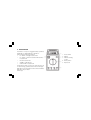
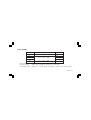
DIGITAL MULTIMETER
Model No: CDM20
PartNo: 4500007
0607
WARNING
Before attempting to open the case, Always be sure that test leads have been disconnected from
measurement circuits. Close case and tighten screws completely before using the meter to avoid
electrical shock hazard.
DO NOT dispose of this product with general household waste. It must be disposed of according to all laws
governing waste electrical and electronic products at a recognised disposal facility
WARNING
Before attempting to open the case, ALWAYS ensure that the test leads have been
disconnected from their measurement circuits. Close the case and tighten the screws
completely before using the meter to avoid the possibility of electric shock
Thank you for purchasing this CLARKE Digital Multimeter.
Please read this leaflet thoroughly and follow the instructions carefully, in doing so you can look forward to
the multimeter giving you long and satisfactory service.
Guarantee
This CLARKE product is guaranteed against faulty manufacture for a period of 12 months from the date of
purchase. Please keep your receipt as proof of purchase.
This guarantee is invalid if the product is found to have keen abused or tampered with in any way, or not
used for the purpose for which it was intended.
Faulty goods should he returned to their place of purchase. No product can he returned to us without prior
permission. This guarantee does not effect sour statutory rights.
CDM-20 Page-2
CONTENTS
PAGE
1.
SAFETY INFORMATION ................................................................................................. 1
1.1
PRELIMINARY ................................................................................................................ 1
1.2
DURING USE ................................................................................................................. 2
1.3
SYMBOLS ....................................................................................................................... 3
1.4
MAINTENANCE ............................................................................................................ 4
2.
DESCRIPTION ................................................................................................................ 5
3.
OPERATING INSTRUCTIONS ......................................................................................... 8
3.1
MEASURINGVOLTAGE ................................................................................................. 8
3.2
MEASURING CURRENT ................................................................................................ 9
3.3
MEASURING RESISTANCE ............................................................................................ 10
3.4
TESTING DIODE ............................................................................................................. 11
3.5
TESTING TRANSISTOR ................................................................................................... 11
CDM-20 Page-3
3.6
CONTINUITY TEST .......................................................................................................... 12
4.
SPECIFICATIONS ........................................................................................................... 13
4.1
GENERAL ...................................................................................................................... 13
4.2
DC VOLTAGE ............................................................................................................... 15
4.3
AC VOLTAGE ............................................................................................................... 16
4.4
DC CURRENT ................................................................................................................ 17
4.5
ACCURRENT ................................................................................................................. 18
4.6
RESISTANCE .................................................................................................................. 19
4.7
DIODE AND AUDIBLE CONTINUITY TEST ..................................................................... 20
4.8
TRANSISTOR liFE TEST .................................................................................................... 20
5.
ACCESSORIES .............................................................................................................. 21
6.
BATTERY & FUSE REPLACEMENT .................................................................................. 21
CDM-20 Page-4
1. SAFETY PRECAUTIONS
This multimeter has been designed according to lEG-lOb concerning electronic measuring instruments with
an overvoltage category (CAT II) and pollution 2.
Follow all safety and operating instructions to ensure that the meter is used safely and is kept in good
operating condition.
1.1
❉
❉
PRELIMINARY
When using this meter, the user must observe all normal safety rules concerning:
•
Protection against the dangers of electronic current.
•
Protection of the meter against misuse.
Full compliance with safety standards can be guaranteed only if used with the test leads supplied. If
necessary, they must be replaced with the same model or same electronic ratings. Measuring leads
must be in good condition. Replacements are available from CLARKE International - see back page.
CDM-20 Page-5
1.2 DURING USE
❉
Never exceed the protection limit values indicated in specifications for each range of measurement.
❉
When the meter is linked to measurement circuit, do not touch unused terminals.
❉
When the value scale to be measured is unknown before hand, set the range selector at the highest
position.
❉
Before rotating the range selector to change functions, disconnect test leads from the circuit under
test.
❉
Never perform resistance measurements on live circuits.
❉
Always be careful when working with voltage above 60V dc or 30V AC rms. Keep fingers behind the
probe barriers while measuring.
❉
Before attempting to insert transistors for testing, always be sure that test leads have been
disconnected from any measurement circuits.
❉
Components should not be connected to the hFE socket when making voltage measurements with
test leads.
CDM-20 Page-6
1.3 SYMBOLS
Important safety information, refer to the operating manual.
Dangerous voltage may be present.
Earth ground.
Double insulation ( Protection class II).
A Fuse must be replaced with ratings specified in the manual.
1.4 MAINTENANCE
❉
Before opening the meter, always disconnect test leads from all sources of electric current.
❉
For continue protection against fire, replace fuse only with the specified voltage and current rating:
F 2A1250V (quick acting).
❉
❉
If any faults or abnormalities are observed, the meter cannot be used. It must be inspected and
repaired by a qualified technician, or returned to CLARKE International for repair.
❉
Never use the meter unless the back cover is in place and fastened fully.
❉
Do not use abrasives or solvents on the meter, use a damp cloth and mild detergent only.
CDM-20 Page-7
2. DESCRIPTION
This meter is a compact, rugged, battery operated,
handheld 3 ½ digit multimeter, capable of
performing the following functions:
0.888
1. Power Switch
•
DC and AC voltage measurement
2. Display
•
DC and AC current measurement Resistance
measurement
3. Transistor Testing
Socket
•
Diode measurement
4. Rotary Switch
•
Audible continuity test
5. Input Jacks
•
Transistor hEE measurement
The Dual-slope A/D Convert uses CMOS technology
for auto-Zeroing, polarity selection and overrange
indication. Full overload protection and low battery
indication are provided
CDM-20 Page-8
2.1 POWER SWITCH
A push - push switch is used to turn the meter on or off.
2.2 DISPLAY
3 ½ digit, 7 segment, 18mm high LCD.
2.3 FUNCTION AND RANGE SELECTOR
There are different functions and 32 ranges provided. A rotary switch is used to select functions and ranges.
2.4 INPUT JACKS
1.
“COM” jack - Plug in connector for black (negative) test lead
2.
“V/Ω” jack - Plug in connector for red (positive) test lead for voltage and resistance.
3.
“2A” jack - Plug in connector for red test lead for current (2A MAX).
4.
“10A” jack - Plug in connector for red test lead for 10A measurement.
CDM-20 Page-9
3.
OPERATING INSTRUCTIONS
3.1 MEASURING VOLTAGE
1.
2.
Connect the black test lead to the COM jack and the red test lead to the V/Q jack.
Set the rotary switch at the desired V or V ~ range position and connect test leads across the source
or load under measurement.
The polarity of the red lead connection will be indicates along with the voltage value when making
DC voltage measurement.
3.
When only the figure 1 is displayed, it indicates overrange situation and the higher range has to be
selected
CDM-20 Page-10
3.2 MEASURING CURRENT
1.
2.
Connect the black test lead to the COM jack and the red test lead to the A jack for a maximum of
2A current For a maximum of 20A, move the red lead to the 10A jack.
Set the rotary switch at desired A or A~ range position and connect test leads in series with the load
under measurement
The polarity of the red lead connection will be indicated along with the current value when making
DC current measurement.
3.
When only the figure “1” displayed, it indicates overrange situation and the higher range has to be
selected
CDM-20 Page-11
3.3 MEASURING RESISTANCE
1.
Connect the black test lead to the COM jack and the red test lead to the V/Ω jack. (The polarity of
red lead is “+” )
2.
Set the rotary switch at desired Q position and connect test leads across the resistor under
measurement.
NOTE
1.
If the resistance being measured exceeds the maximum value of the range selected or the input is
not connected, an overrange indication “1” will be displayed.
2.
When checking in-circuit resistance, be sure the circuit under test has all power removed and that all
capacitors have been fully discharged .
3.
For measuring resistances above 1M Ω the meter may take a few seconds to stabilise. This is normal
for high resistance measurements.
CDM-20 Page-12
3.4 TESTING DIODE
1.
Connect the black test lead to the COM jack and the red test lead to the V/Ω jack. (The polarity of
red lead is “+”.
2.
Set the rotary switch at the
position and connect red lead to the anode, black lead to the
cathode of the diode under testing. The meter will show the approx. forward voltage of the diode. If
the lead connection is reversed, only figure “1” displayed.
3.5 TESTING TRANSISTOR
1.
Set the rotary switch at hFE position.
2.
Determine whether the transistor to be tested is NPN or PNP type and locate the Emitter, Base and
Collector leads. Insert leads of the transistor into proper holes of the transistor testing socket.
3.
The meter will show the approx. hFE value at test condition of base current 10µA and Vce 2.8V.
3.6 CONTINUITY TEST
1.
Connect the black test lead to the COM jack and the red test lead to the V/Ω jack. (The polarity of
the red lead is positive “+”
2.
Set the rotary switch at
position and connect test leads across two points of the circuit under test.
If continuity exists (i.e. resistance less than about 30Ω), built-in buzzer will sound.
CDM-20 Page-13
4.SPECIFICATIONS
Accuracy is specified for a period one year after calibration and at 18º C to 28º C (64º F to 82º F) with
relative humidity to 80 %.
4.1 GENERAL
Maximum Voltage between ............................................... CAT II 1000V.
Teminal and Earth Ground .................................................. CAT III 600V.
Fuse Protection ..................................................................... A: F 2A1250V; 10A: unfused.
Power Supply ........................................................................ 9V battery, Neda 1604 or 6F22.
Display ................................................................................... LCD, 1999 counts, updates 2-3/sec.
Measuring Method ............................................................... Dual-Slope integration ND converter.
Overrange indication .......................................................... “1” figure only on the display.
CDM-20 Page-14
Polarity indication ................................................................ “-” displayed for negative polarity.
Operating Temperature ...................................................... 0ºC to40ºC (32ºF to l04ºF).
Storage Temperature ........................................................... 10ºC to 50ºC (14ºF to 122ºF).
Temp for guaranteed accuracy ........................................ 23ºC ± 5ºC.
Low Battery Indication ......................................................... appears on the display.
Size ( W x L x H) ...................................................................... 88W x 172L x 36H mm.
Weight .................................................................................... 370g (including battery).
CDM-20 Page-15
4.2 DC VOLTAGE
Range
Accuracy
Resolution
200mV
100µV
2V
1mV
20V
± 0.5% of rdg ±1 digits
10mV
200V
l00mV
1000V
lV
Input Impedance: 10MΩ on all ranges.
Overload Protection: 250 V rms AC for 200mV range, 1000 V peak or 700 V rms AC for other ranges
CDM-20 Page-16
4.3 AC VOLTAGE
Range
Accuracy
200mV
±1.2 % of rdg + 3 digits
100µV
±0.8 % of rdg + 3 digits
10mV
±1.2% of rdg + 3 digits
1V
2V
20V
1 mV
200V
700V
Resolution
l00mV
Input Impedance:
10MΩ on all ranges.
Frequency Range:
40Hz to 1 kHz; Indication: Average (rms of sine wave).
Overload Protection: 250V rms AC for 200mV range and 1000V DC or 700V rms AC for other ranges.
CDM-20 Page-17
4.4 DC CURRENT
Range
20µA
Accuracy
Resolution
± 2.0 % of rdg+ 5 digits
10nA
±0.8% of rdg + 1 digits
1µA
± 1.2 % of rdg ± 1 digits
100µA
±2.0% of rdg + 5 digits
l0mA
200µA
2mA
0.1µA
20mA
200mA
10µA
2A
10A
1mA
Max Input Current:
2A:2A. 10A:10A continuous, 20A 15 sec.MAX.
Overload Protection:
2A/250V fuse (10A range unfused); Measuring Voltage Drop: 200mV
CDM-20 Page-18
4.5 AC CURRENT
Range
20µA
Accuracy
l0nA
±1.0% of rdg + 3digits
1µA
± 1.8% of rdg 3 digits
100µA
± 3.0% of rdg + 7 digits
l0mA
200µA
2mA
0 .1µA
20mA
200mA
10µA
2A
10A
Resolution
±3.0% of rdg + 7digits
1mA
Max Input Current:
2A2A. 10A10A continuous, .20A 15 sec MAX
Overload Protection:
2A/250V fuse (10A range unfused); Frequency Range 40Hz to 1kHz
Indication:
Average (rms of sine wave) Measuring Voltage Drop 200mV
CDM-20 Page-19
4.6 RESISTANCE
Range
200Ω
Accuracy
Resolution
±0.5% of rdg + 3 digits
0.1Ω
±0.5% of rdg + 1 digit
10Ω
2KΩ
20KΩ
1Ω
200kΩ
100Ω
2MΩ
20MΩ
1 KΩ
±1.0% of rdg + 2digits
Overload Protection:
250V DC/AC rms on all ranges.
Open Circuit Voltage: Less than 700mV.
CDM-20 Page-20
10KΩ
4.7 Diode and Audible Continuity Test
Range
Description
Test Condition
Display read approximate forward
Forward DC current approximately 1mA.
voltage of diode
Reversed DC voltage approximately 2.8V.
Built-in buzzer sounds ifresistance is
Open Circuit Voltage approximately 2.8V.
less than approximately 30Ω
Overload Protection: Sounds alarm (250V AC/DC rms)
4.8 Fransistor hEE Test
Range
Description
hFE
Display read approximate hFE value
(0-1000) transistor under test (ALL TYPE)
Test Condition
Base Current approx l0µA VCE
approximately 2.8V.
CDM-20 Page-21
5. ACCESSORIES
Test leads
Electric Rating 1500V, 10A MASTECH HYTL — 095
Battery
9V NEDA 1604 or 6F22
Operating Manual
HYS004343
6. BATTERY & FUSE REPLACEMENT
If the sign -+ appears on the LCD display, it indicates that battery should be replaced. Remove screws
on the back cover and open the case. Replace the exhausted battery with a new one.
The fuse should rarely need replacement and will blow almost always as a result of operator error. Open
the case and replace the blown fuse with the ratings specified: F 2A/250V (quick acting).
CDM-20 Page-22