1
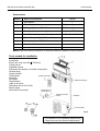
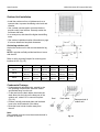
INSTALLATION, OPERATION & MAINTENANCE MANUAL VMH 09/12/18/24 SD Inverter Single Zone Ductless Mini-Split Heat Controller • 1900 Wellworth Ave. • Jackson, MI 49203 • (517)787-2100 • www.heatcontroller.com VMH 09/12/18/24 SD Inverter Mini-Split Heat Controller TABLE OF CONTENTS Safety Precautions Warnings and Cautions........................................................................................................ 3 Installation Instructions Installation Location Selection........................................................................................... 4-5 Accessories.......................................................................................................................... 6 Indoor unit installation........................................................................................................ 7-8 Outdoor unit installation........................................................................................................ 9 Refrigerant Pipe Connection Refrigerant line set installation........................................................................................... 10 Leak test, evaluation and release of refrigerant................................................................. 11 Electrical Work Electrical Precautions......................................................................................................... 11 Unit wiring........................................................................................................................... 12 Initial Start Up and Checks Indoor/outdoor communication cable................................................................................. 13 Outdoor power/communication wiring................................................................................ 14 Field charging and final inspection..................................................................................... 15 ! Caution • Contact an authorized service technician for repair or maintenance of this unit • Contact an authorized installed for installation of this unit. • Installation work must be performed in accordance with local and national electrical codes and standards by authorized personnel only 2 Heat Controller VMH 09/12/18/24 SD Inverter Mini-Split • Read the follow SAFETY PRECAUTIONS carefully before installation. • Electrical work must be performed by a licensed electrician. Be sure to use the correct rating of the power cord and main circuit for the model to be installed. • Incorrect installation due to ignoring the instructions will cause harm or damage. n The seriousness is classified by the following indications. ! WARNING! ! This symbol indicates the possibility of death or serious injury. CAUTION! This symbol indicates the possibility of injury or damage to property. The items to be followed are classified by the symbols: This symbol denotes item that is PROHIBITED from doing. ! 1) 2) 3) 4) 5) 6) 7) 8) 9) 1) 2) 3) WARNING! Do not install without an authorized servicer/installer. Install according to this installation instruction. If installation is defective, it can cause water leakage, or electrical shock/fire. Use the supplied accessories and specified parts for installation. Install the indoor unit on a wall strong enough to hold the unit’s weight. Install the outdoor unit on a raised concrete pad or blocks to provide a solid, level foundation. In a location with high winds, anchor the unit and provide an air baffle. In snowy areas (for heat pump models), install the outdoor unit on a raised platform higher than drifting snow. Provide snow vents. For electrical work, follow local and national electric codes and these installation instructions. An independent circuit and single outlet must be used. If electrical circuit capacity is not enough or defects are found in electrical work, it will cause electrical shock or fire. Use the specified cable and connect tightly. Clamp the cable so that no external force will stress the connections. Loose wiring may overheat at the connection points and create a possible fire hazard. Wiring routing must be properly arranged so that control board cover is fixed properly. If control board cover is not fixed perfectly, it will cause overheating at connection point of terminal, fire or electrical shock. When charging the unit, take care not to let air/substances other than the specified refrigerant go into refrigeration cycle. Otherwise, it will cause lower capacity, abnormal high pressure in the refrigeration cycle, explosion and injury. Do not modify the length of the power supply cord or use an extension cord, and do not share the single outlet with other electrical appliances. Otherwise, it will cause fire or electrical shock. ! CAUTION! This equipment must be grounded It may cause electrical shock if grounding work doesn’t comply with local/national electric codes. Do not install the unit at place where leakage of flammable gas may occur. If gas leaks and accumulates near the unit, it may cause fire. Carry out drainage piping as mentioned in installation instructions. If not done correctly, water may enter the room and damage personal belongings. 3 VMH 09/12/18/24 SD Inverter Mini-Split Heat Controller Selecting installation place Choose a location that places the outdoor unit as close to the indoor unit as possible. The maximum unit separation and vertical lift (compressor above the evaporator) must be taking into account. Do not exceed allowable refrigerant line lengths. More than 6in.(15cm) Indoor unit • Unit must be installed in a location that does not obstruct the flow of air and ensures clearances are maintained. (Fig. 1) • The site must support the weight of the unit. • The site must be easily accessible for cleaning or replacement of the air filter, maintenance and service. • The indoor unit should be mounted as high up on the wall toward the ceiling, leaving a minimum of 6” (150mm) of space between the ceiling and the top of the indoor unit. (Fig. 1) • Due to the possibility of electronic interference with other devices, it is recommended that there should be at least 3 ft (1 meter) between the unit and other devices/appliances such as televisions or radios. • The unit should be installed away from possible exposure to fire, smoke, of flammable gases and be protected from direct sunlight (sunlight can interfere with the signal between the unit and the remote controller. More than 5in.(12cm) More than 5in.(12cm) More than 6.5ft.(2.0cm) Fig. 1 More than 12in.(30cm) More than 12in.(30cm) Outdoor unit More than 24in.(60cm) • If installation location allows the unit to be exposed to strong winds (such as coastal applications), ensure that the unit has a wind barrier. This will assist with preventing strong gusts of wind from entering the unit’s cabinet and interfering with the fan operation. (Fig. 3 and Fig. 4) More than 10ft.(200cm) Fig. 2 Fig. 4 Fig. 3 Incorrect Correct Barrier Strong wind wind gusts Strong wind Correct Incorrect 4 Heat Controller VMH 09/12/18/24 SD Inverter Mini-Split • Avoid areas where water, snow, or ice may fall from the roof onto the unit. • In climates where snow is a consideration, locate the unit away from areas prone to drifting. • Ensure the location of the unit will not be subject to snow drifts, heavy accumulation of snow or leaves or other seasonal debris. If unavailable, provide an awning for the unit. (Fig. 5 and Fig. 6) 1. An awning can be built over the outdoor unit to prevent direct sunlight, rain exposure, or snowfall. 2. Ensure that the awning does not impede the unit’s required clearances or obstruct air flow. 3. The awning should be at least 2 ft. (0.6m) away from the top of the unit’s housing. • Ensure free flow of air into and out of the unit. All air inlet/outlets should be free of obstructions such as walls and shrubs. Minimum clearances should be maintained. (Fig. 2) • During heating and defrost modes (heat pump models only), the condensate should be properly drained away from the unit. Use the included drain joint and seal along with locally purchased hose to do so. (Fig. 8) • Do not locate two or more units in any way that will block discharge air from one unit to another. Be certain that hot air from one unit will not blow into a nearby unit to prevent recirculation or discharge air. (Fig. 7) Fig. 5 Fig. 6 More than 1ft (30cm) More than 1ft (30cm) More than 2ft (60cm) (Service space) Fence or Obstacles More than 2ft (60cm) More than 2.5ft (70cm) Fig. 7 Rooftop installation • If the outdoor unit is installed on a roof structure, be sure to level the unit. • Ensure the roof structure and anchoring method are adequate for the unit location. • Consult local codes regarding rooftop mounting. • If the outdoor unit is installed on roof structures or external walls, this may result in excessive noise and vibration, and may also be considered a non-serviceable installation. • Oil traps must be made in the refrigerant line set (every 10 ft.) when the outdoor unit is located above the indoor unit. 5 VMH 09/12/18/24 SD Inverter Mini-Split Heat Controller Accessories Number Name of Accessories 1 Wall Bracket 2 Plastic Dry Wall Anchor 5-8 depending on model 3 Self-tapping Screw A ST 3.9X25 5-8 depending on model 4 Seal (heat pump models only) 1 (Part 202720090001) 5 Drain Elbow (heat pump models only) 1 (Part 201101020011) 6 Remote Controller (with 2 AAA batteries) 1 7 Self-tapping Screw B ST2.9X10 2 8 Remote controller holder1 9 Nano silver air filter (field installed, not shown) Qty/unit 1 2 Note: Except for the parts provided above, all other parts needed for installation must be purchased . Tools needed for installation: Level gauge Screwdriver Electric drill, Hole core drill o 2.5”(65mm) Flaring tool set Adjustable wrench Refrigerant leak detector or a bottle of soap water Vacuum pump Gauge manifold Thermometer Remote Controller Multimeter 6 Pipe cutter Tape Measure Cable to wire units Refrigerant line set for R-410A Micron gauge Mounting screw Allen wrench set (metric) ST2.9x10-C-H 7 Seal 8 Air F ilter Additional drain pipe Remote Controller holder Insulation Drain Elbow “U” bend (cable) Fig. 8 • This illustration is for explanation purposes only. • Copper lines must be insulated independently. 6 Heat Controller VMH 09/12/18/24 SD Inverter Mini-Split Wall Bracket should be flush with the interior wall Indoor unit installation 1. Wall Bracket Mounting A. There are two tabs on the back of the indoor unit that hold the wall bracket onto the unit. Press them down with a flat head screwdriver to release the wall bracket from the back of the unit. B. Mount the wall bracket flush on structural parts (studs) of the wall with proper unit clearances in consideration. (Fig. 1 and Fig. 9) NOTE: Any space between the unit and the wall may cause noise or vibration. C. Screw the wall bracket onto the wall with type “A” self-tapping screws. If the wall is made of brick, concrete or the like, drill 1/4” (5mm) diameter pilot holes in the wall. Use anchors in conjunction with mounting screws. NOTE: • Drill holes in the wall according to the stud locations and corresponding mounting points on the actual wall bracket that comes with your unit. Wall brackets may vary by model and specifications are subject to change. • It is important to use all screws provided to secure the wall bracket to the wall. Fig. 9 R L VMH 09 Model (4.3in) 110mm (7.1in) 180mm VMH 12 (4.3in) 110mm (5.5in) 140mm VMH 18 (5.3in) 135mm (10.2in) 260mm Model VMH 24 H Hole Diameter (1.8in) 45mm 02.56 in (65mm) R L H Hole Diameter (10.8in) 275mm (10.8in) 275mm (1.8in) 45mm 02.56 in (65mm) 2. Create Opening for refrigerant and condensate lines A. Determine hole position according to the wall bracket that comes with your unit, the unit’s required clearances (Fig. 1) and which direction (left/right) the lines will be routed from the back of your unit (Fig. 14). Drill 2.5”(65mm) hole angled downward (approx. 45°) toward the outdoors. (Fig. 11). NOTE: Ensure that neither studs nor plumbing are located directly behind the proposed hole location. B. Always use a conduit to route the piping through the hole in the wall. Properly seal the hole after routing the pipes through to prevent debris, insects, or small animals from entering. Fig. 10 Wall Outdoor 45° Indoor Fig. 11 Fig. 12 3. Condensate Drainage A. Run the drain hose sloping downward. Do not trap the drain hose. Do not install the drain hose as illustrated in Fig.12. B. When extending the drain hose, with locally purchased hose, insulate the connection with armaflex or similar pipe insulation material. (Fig. 13) Do not block water flow by a rise Pipe Insulation Drain hose 7 Wall Cap Fig. 13 Do not put the end of drain hose into water Wall Extension drainhose VMH 09/12/18/24 SD Inverter Mini-Split Heat Controller 4. Refrigerant Line Installation A. Remove the knockout from the desired side of the unit that the line set will be routed from. The lines from the unit can be routed either left or right, left back or right back (Fig. 14). Clamp B. Remove the clamp (Fig. 14) before attempting to bend the line set to prevent kinks. The clamp may be replaced and used to hold the line set in place, but this depends on the routing direction of the line set and whether it is needed, taking into account the line’s bend radius. Knockout Left Knockout Left Back Right Right back Fig. 14 C. Loosely run the line set connections from the indoor unit through the hole in the wall. D. Hang the unit onto the top flanges of the wall bracket. Ensure the unit is properly seated. (Fig. 15) Top Flange E. Keep the unit away from the wall to prevent the line set from being kinked or crushed, use a piece of styrofoam as a spacer between the back of the unit and the wall. (Fig. 16) Bottom Flange F. Feed the condensate drain line and refrigerant line set through the hole such that the unit can sit flush against the wall then remove the spacer. Fig. 15 G.Push the bottom of the unit up and onto the lower flanges of the wall bracket. Ensure that unit is properly sealed. Spacer H. Be sure that the overall installation of the indoor unit and installation plate are flush against the wall and level. 5. Piping and insulating Fig. 16 A. Bundle the tubing, connecting cable*, and drain hose with tape or wire ties as shown in (Fig.17). Indoor Unit B. Be sure to arrange the drain line such that it is at the lowest point within the bundle as they exit the unit and hole in the wall to the outdoors. (Fig. 17) Ponding box *Connecting Cable C. Because the condensed water from rear of the indoor unit is gathered in the ponding, do not put anything else in this area. Tape/wire tie Drain line Fig. 17 D.Insulated the liquid line and suction lines separately. 8 Line set Heat Controller VMH 09/12/18/24 SD Inverter Mini-Split Outdoor Unit Installation • Install the outdoor unit on a rigid base such as a concrete slab, to prevent increasing noise level and vibration. • Use a raised concrete pad or concrete blocks to provide a solid, level surface. Securely anchor the unit down with bolts. • In a snowy area, slab should be higher than drifting snow. • See outdoor installation location information on page 4 for more details and acquired clearances. Air inlet Anchoring outdoor unit Air inlet Anchor the outdoor unit to the concrete slab with lag bolts. NOTE: Lag bolts are field provided and do not come with the unit. W1 Air outlet Refer to unit’s mounting footprint for mounting hole locations A & B. (Fig. 18) Fig. 18 W H D W1 A B VMH 09 VMH 12 29.9 in. (760 mm) 11.2 in. (285 mm) 23.2 in. (590 mm) 32.4 in. (823 mm) 20.9 in. (530 mm) 11.4 in. (290 mm) VMH18 33.3 in. (845 mm) 12.6 in. (320 mm) 27.6 in. (700 mm) 35.7 in. (908 mm) 22.0 in. (560 mm) 13.2 in. (335 mm) VMH 24 36.7 in. (900 mm) 12.9 in. (315 mm) 35.1 in. (860 mm) 40 in. (980 mm) 24.1 in. (590 mm) 13.6 in. (333 mm) Model Condensate Drainage • Condensate and defrosted water, created by the unit operating in heat mode, should be routed and drained away from the unit. • Fit the seal onto the drain elbow, then insert the drain elbow into the hole on the base pan of the outdoor unit, rotate it 90° to secure into place. (Fig. 19) • Connect a locally purchased drain and insulated hose to the hose barb end of the elbow. • Route the hose to drain location away from the unit. Seal Note: Some models may have more then one drain hole in the base of the unit. Drain elbow Fig. 19 9 Base pan hole of outdoor unit VMH 09/12/18/24 SD Inverter Mini-Split Heat Controller Refrigerant Line Set Installation Refrigerant Line Set Installation • Use copper tubing suitable to withstand pressures for R-410A refrigerant. We recommend a min. wall thickness of 0.027in. (0.7mm). 11. The tube size should always be the same diameter as the connections provided at the service valves of the outdoor unit. Note: On some models, a reducer or an expander may be shipped with the indoor unit in order to adapt the line set connection to the proper size to mate with the indoor unit’s connection. Be sure to check for this part, should you discover that the outdoor units service valve sizes differ from the indoor unit. If this part is shipped with the indoor unit, then it is required to be used. 12.Up sizing/downsizing the refrigerant lines/ connections can result in inadequate oil return to the compressor or excessive refrigerant return and will void the warranty. 13.Do not over torque the connections, excessive force can break the flare nut. 14. When routing the line set between the outdoor and indoor units: A. Support the tubing adequately to avoid sags that can trap the oil. B. Isolate the tubing so it does not transmit noise from vibration into the structure of the building. C. Avoid sharp edges that could cut the tubes. D. Trap rises every 10 ft. (5-7m) with a ‘p’ trap. When outdoor unit mounted above indoor unit. 1. Purchase line sets through a Heat Controller distributor with consideration of the minimum and maximum line lengths. (Fig, 20) 2. Ductless mini-splits require both-liquid and suction-lines to be insulated. 3. Connections are made via flare nuts. 4. The number of bends and length of refrigerant lines determine the pressure drop which affects capacity and efficiency of the system, as well as oil return. Minimize the length and number of bends when possible during installation. 5. Minimum line set length must be maintained, even if the installation does not require it. Extra length that is unnecessary can be coiled up near the outdoor unit (Do not to block air inlets/outlets). 6.Choose a location that places the outdoor unit as close to the indoor unit as possible to minimize line set lengths. 7. Use only clean, refrigerant grade tubing suitable for R-410A. 8. Avoid installing refrigerant lines on wet/rainy days. 9. Always keep tube ends sealed until the final connections are to be made. 10. If line sets are being made at the time of installation, rather than being purchased, be sure to: • Remove burrs from cut ends of the tubing • Use tube benders to prevent kinking. • Ensure tube cuts are square in relation to the end of the tube. • Use the proper diameter tube and flare nut sizes recommended by the manufacturer. • Insulate both lines with Amraflex of equivalent with a wall thickness of at least 3/8”. Fig. 20 Model No. Refrigerant Piping VMH 09 VMH 12/18 VMH 24 Liquid Side-Gas Side Inch 1/4 - 3/8 1/4 - 1/2 3/8 - 5/8 Max. Refrigerant Pipe Length Unit Separation* Ft. (m) 82 (25) 82 (25) 98 (30) 98 (30) Max. Level Difference/Vertical Lift** Ft. (m) 33 (10) 33 (10) 66 (20) 66 (20) *Minimum pipe length must not be less that 10 feet. ** Trap rises every 10 feet (5-7m) with a ‘p’ trap when outdoor unit is mounted above the indoor unit. 10 Heat Controller VMH 09/12/18/24 SD Inverter Mini-Split Leak Test, Evacuation & Release of Refrigerant WARNING It is illegal to discharge refrigerant into the atmosphere. Use proper reclaiming methods and equipment when working on the refrigerant containing parts of the unit. Service should be performed by a QUALIFIED service agency and certified technicians. The condensing unit is supplied with a R-410a factory approximately 25 ft. (7.6m) of line charge, sufficient for most matching evaporator units. Charge must be added for interconnecting tubing. See Field Charging Section of this manual. The unit’s service valves are shipped in the closed position and should not be opened until final connections and evacuation are completed. Electrical Precautions The recommended procedure for leak test, evacuation, and release of refrigerant is outlined below: 1. Complete the final piping connections to the indoor and outdoor units using high temperature brazing alloy. 2. Connect a charging manifold to the service ports provided at the service valves. 3. Pressurize the lines and evaporator with nitrogen and leak check all connections with soap bubbles. Repair as necessary any faulty joints. If brazing is required be sure to RELEASE THE NITROGEN FIRST. Re-test as needed. 4. Connect a vacuum pump to the manifold center connection, start the pump and open the manifold valves. 5. Evacuate to 500 microns or less for a minimum of 30 minutes. Close the manifold valves and shut off the pump. Note the vacuum reading and wait 15 minutes. Take a new vacuum reading. A reading of 800 microns or higher indicates the presence of moisture or a leak. 6. Repair as necessary and repeat steps 3, 4 & 5. 7. Confirm that manifold valves are closed and disconnect the vacuum pump. 8. Remove the caps from the services valves. Open the valves to the fully ‘back-seat’ position. Replace service valve caps and tighten. CAUTION 1. Refer to the unit’s rating plate for power supply voltage. Ensure adequate electrical supply is available. 2. Ensure the air conditioner is properly grounded. 3. Connect wiring to the unit according to the electrical diagram located on the unit. 4. All wiring must comply with local and national electrical codes and be installed by a qualified electrician. 5. An individual branch circuit must be available. 6. Properly size the HACR breaker/fuse based on nameplate date. 7. Improper connections and inadequate grounding can cause injury or death. 8. Connect all wiring tightly. Loose wiring may cause overheating at connection points and create a possible fire hazard. 9. Match terminal strip numbers/labels and colors between indoor and outdoor wiring. Erroneous wiring may cause fire/shock. 10. Always use strain reliefs and outdoor cable cover to protect wiring. 11 VMH 09/12/18/24 SD Inverter Mini-Split Heat Controller Unit Wiring The contractor is to provide an individual branch circuit for over current protection for the unit as required by code. Some codes may require a disconnect between the indoor and outdoor unit. Run power supply wiring through a weatherproof disconnect box and conduit to the unit connection. Disconnects are required to be within sight and easy reach of the unit (usually within 3 feet). Circuit breakers and disconnect switches should be properly sized based on the required codes and the unit’s nameplate requirements. (Fig.21) WARNING • Before performing any electrical work, ensure all power is off. Electrical shock may occur. • All outdoor unit’s capacitor’s to discharge otherwise electrical shock hazard may occur. • Ensure the unit is properly grounded. Check the unit wiring diagram for the number of conductors required. Ensure that the proper AWG (gauge) and type of wired is used to comply with code and the unit’s nameplate. Route neatly and protect from sharp edges and damage. ELECTRICAL WIRING AND SUPPLY VOLTAGE: All electrical wiring must be done according to local codes. Additionally installations in the USA, must conform to the current National Electric Code (NEC) and Installations in Canada must conform to current Canadian Electric Code (CEC). Nameplate data indicates the operating voltage, phase, ampacity, maximum over current protection, and minimum voltage. Inadequate wiring and/or improper electrical supply will likely result in failure of the compressor and other electrical components and voids the warranty. Model BTUH/H 9 12 18 24 POWER (outdoor) PHASE 1 Phase 1 Phase 1 Phase 1 Phase VOLT 208/230V 208/230V 208/230V 208/230V CIRCUIT BREAKER/FUSE (A) 15 15 20 25 MINIMUM CIRCUIT AMPACITY 9 9 13 15 NOTE: Subject to change. Always refer to unit’s nameplate. Fig. 21 Power supply cord Power supply 1 o 208-230V~60Hz Branch circuit breaker 12 Heat Controller VMH 09/12/18/24 SD Inverter Mini-Split Electrical Work Indoor/Outdoor Communicating Cable Indoor Wiring 1. Wiring must conform to local and national electric codes 2. Lift the indoor unit’s panel up, remove the electrical box cover by loosening the screw as shown in (Fig.22). Fig. 22 Panel 3. Connect each conductor to the terminal of the indoor unit (L1, L2, S and Ground) based on the labels of each terminal (Fig. 23). 4. Use strain relief to secure the cable (Fig. 23). 5. Ensure the wire color and location to and from each terminal are identical between the indoor and outdoor terminal strips. Electrical box cover 6. Wrap any loose cables not connected with terminals with electrical tape, so that they will not touch any electrical components. Terminal block of indoor unit 7.Refer to the wiring diagram located on the outdoor unit and/or under the front panel of the indoor unit for proper wiring or 8. Heat Controller recommends using 600V THHN 14AWG/4 conductor unshielded stranded copper cable, however local and national codes for wire should always be followed based on your specific application. To outdoor unit To outdoor unit Fig. 23 13 VMH 09/12/18/24 SD Inverter Mini-Split Heat Controller Electrical Work Outdoor unit power and communication cable wiring Outdoor Unit To power supply 1. Remove the electrical control cover from the outdoor unit (Fig. 24). Ov er 1 2. Connect power supply wires to the right side of the outdoor unit’s terminal strip. (Fig. 25) 3/4 in. (40 mm ) Conduit panel 3. Connect the green/yellow ground from the power supply wire to ground terminal. (Fig. 25) Connecting cable Power supply cord 4. Connect the communication cable from the indoor unit to the outdoor unit’s terminal strip on the left side. (Fig. 25) Cover control Fig. 24 5. Connect the ground wire of the communication cable to the ground terminal. (Fig. 25) 6. To prevent water from entering in the unit, form a loop in the cable (Fig. 26). 7. Insulate any unused conductors with electrical tape, so that they do not touch any other exposed electrical or metal parts. Fig. 26 Fig. 25 Terminal block of outdoor unit Air inlet(rear) Air inlet(side) Cover To indoor unit To power supply OR Screw Loop the cable Air outlet To indoor unit 14 To power supply Heat Controller VMH 09/12/18/24 SD Inverter Mini-Split Initial Start-Up & Checks FIELD CHARGING Operation of the unit will depend on the setting of the thermostat on the unit or the remote control. Refer to the owner’s manual and remote control manual for operating instructions. Unit performance, efficiency, and life depends, to a large extent, on a proper system charge. Time spent on getting the charge right at start-up will payoff in the long run. Operating conditions such as voltage, air flow, evaporator coil size, and indoor and outdoor temperature and humidity all have an effect on the system pressures and superheat conditions. IMPORTANT! All panels must be installed, main power turned on and the wiring, refrigerant lines, and condensate drain lines properly connected before operating the unit. Condensing units are factory charged for the outdoor and indoor unit with 25ft. (7.6m) of refrigerant lines. Charge must be added for the interconnecting tubing. Test-Run / Initial Start-up 1. Press the ON/OFF button on the remote control to turn the unit on. 2. Press the mode button on the remote control to check that each mode (Cool, Heat*, Auto, Dry and Fan only) works properly. 3. When the ambient temperature is too low (below 62°F/16°C) to run the unit in cooling mode to check the system, the unit can be placed in manual operation. 4. To place the unit in manual operation, gently lift up the lower left and right sides of the front panel unit it opens and clicks into a locked position where it props itself open. 5. Under the unit’s front panel the cover to the indoor electrical terminal strip has an oval shaped opening labeled “AUTO/COOL”. Through this opening, the “AUTO/COOL” button can be accessed with a long, thin object, such as a pen/flathead screwdriver. 6. Press the “AUTO/COOL” button and manual operation will begin. 7. Manual operation will allow the unit to run for 30 minutes while any final inspections are made. These units should be critically charged to ensure proper performance. Some systems may require additional charging of refrigerant, depending on line set lengths. R = T X (L-25)ft R(oz): Additional refrigerant to be charged L(ft): The length of the refrigerant line T(oz): The quantity of the charged refrigerant per additional foot. Model oz/ft 09, 12, 18 24 0.16 0.32 FINAL INSPECTION Do a final visual inspection of the entire installation. Complete any final details and clean up. Review Unit and Remote Control Operation with the homeowner/user. Ensure homeowner/user is provided with all manuals, warranty cards, etc. o AUTO/COOL Manual control button Fig. 27 15 VMH 09/12/18/24 SD Inverter Mini-Split Heat Controller 'XHWRRQJRLQJSURGXFWLPSURYHPHQWVVSHFLILFDWLRQVDQGGLPHQVLRQVDUH VXEMHFWWRFKDQJHDQGFRUUHFWLRQZLWKRXWQRWLFHRULQFXUULQJREOLJDWLRQV'HWHUPLQLQJWKH DSSOLFDWLRQDQGVXLWDELOLW\IRUXVHRIDQ\SURGXFWLVWKHUHVSRQVLELOLW\RIWKHLQVWDOOHU $GGLWLRQDOO\WKHLQVWDOOHULVUHVSRQVLEOHIRUYHULI\LQJGLPHQVLRQDOGDWDRQWKHDFWXDOSURGXFW SULRUWREHJLQQLQJDQ\LQVWDOODWLRQSUHSDUDWLRQV ,QFHQWLYHDQGUHEDWHSURJUDPVKDYHSUHFLVHUHTXLUHPHQWVDVWRSURGXFWSHUIRUPDQFH DQGFHUWLILFDWLRQ$OOSURGXFWVPHHWDSSOLFDEOHUHJXODWLRQVLQHIIHFWRQGDWHRIPDQXIDFWXUH KRZHYHUFHUWLILFDWLRQVDUHQRWQHFHVVDULO\JUDQWHGIRUWKHOLIHRIDSURGXFW 7KHUHIRUHLWLVWKHUHVSRQVLELOLW\RIWKHDSSOLFDQWWRGHWHUPLQHZKHWKHUDVSHFLILF PRGHOTXDOLILHVIRUWKHVHLQFHQWLYHUHEDWHSURJUDPV :HOOZRUWK$YH-DFNVRQ0,3KZZZKHDWFRQWUROOHUFRP 12/2014 16