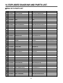
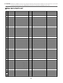
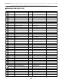
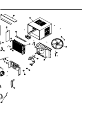
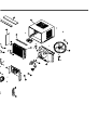
1
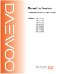
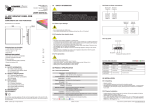
Service Manual
Window Type
Room Air Conditioner
Model: DWB-180CH-R
DWB-240CH-R
DWA-181CH
DWA-186CH
DWA-240CH-R
DWA-246CH-R
✔ Caution
: In this Manual, some parts can be changed for improving, their
performance without notice in the parts list. So, if you need the
latest parts information,please refer to PPL(Parts Price List) in
Service Information Center (http://svc.dwe.co.kr).
DAEWOO ELECTRONICS CORP.
TABLE OF CONTENTS
1. PRECAUTION. . . . . . . . . . . . . . . . . . . . . . . . . . . . . . . . . . . . . . . . . . . . . . . . . . . . . . . . . . . . . . . . . . . . . . . . . . . . . . . 2
2. GENERAL SPECIFICATIONS . . . . . . . . . . . . . . . . . . . . . . . . . . . . . . . . . . . . . . . . . . . . . . . . . . . . . . . . . . . . . . . . 3
3. NAMES OF MAJOR COMPONENTS . . . . . . . . . . . . . . . . . . . . . . . . . . . . . . . . . . . . . . . . . . . . . . . . . . . . . . . . . 4
4. FUNCTION OF MAIN COMPONENTS . . . . . . . . . . . . . . . . . . . . . . . . . . . . . . . . . . . . . . . . . . . . . . . . . . . . . . . . 6
5. GENERAL INFORMATIONS . . . . . . . . . . . . . . . . . . . . . . . . . . . . . . . . . . . . . . . . . . . . . . . . . . . . . . . . . . . . . . . . . 9
6. CARE AND MAINTENANCE . . . . . . . . . . . . . . . . . . . . . . . . . . . . . . . . . . . . . . . . . . . . . . . . . . . . . . . . . . . . . . . . 11
7. ELECTRICAL REQUIREMENTS . . . . . . . . . . . . . . . . . . . . . . . . . . . . . . . . . . . . . . . . . . . . . . . . . . . . . . . . . . . . 13
8. DESCRIPTION OF FUNCTIONS . . . . . . . . . . . . . . . . . . . . . . . . . . . . . . . . . . . . . . . . . . . . . . . . . . . . . . . . . . . . 14
9. WIRING DIAGRAM. . . . . . . . . . . . . . . . . . . . . . . . . . . . . . . . . . . . . . . . . . . . . . . . . . . . . . . . . . . . . . . . . . . . . . . . . 15
10. REFRIGERANT CYCLE . . . . . . . . . . . . . . . . . . . . . . . . . . . . . . . . . . . . . . . . . . . . . . . . . . . . . . . . . . . . . . . . . . . 16
11. PCB DRIVING DESCRIPTION . . . . . . . . . . . . . . . . . . . . . . . . . . . . . . . . . . . . . . . . . . . . . . . . . . . . . . . . . . . . . 17
12. TROUBLE SHOOTING GUIDE. . . . . . . . . . . . . . . . . . . . . . . . . . . . . . . . . . . . . . . . . . . . . . . . . . . . . . . . . . . . . 19
13. HOW TO DISASSEMBLE. . . . . . . . . . . . . . . . . . . . . . . . . . . . . . . . . . . . . . . . . . . . . . . . . . . . . . . . . . . . . . . . . . 22
14. EXPLODED DIAGRAM AND PARTS LIST. . . . . . . . . . . . . . . . . . . . . . . . . . . . . . . . . . . . . . . . . . . . . . . . . . 24
1
1. PRECAUTION
Please observe the following instructions.
1. Turn off unit.
- Make sure the unit is OFF and the AC cord is unplugged before repairing or servicing.
2. In case of checking the circuit unavoidably while the unit is connected with power source, be careful
not to connect with the part of electric charge.
- You may cause electric shock.
3. Use of proper part if you need to replace the part, be sure to use genuine part of servicing model.
- Do not repair or replace the electric contact part.
Consumer must not repair the unit, because it is dangerous.
4. Use of proper tool.
- You must use the proper tool to repair the unit, and use the measuring appliance adjusted accurately.
5. Damage of electric wire and power cord when servicing.
- Check electric wire and a surely replace a damage electric wire and a damage power cord.
6. Never use connecting the middle of wire, after cutting the middle of wire.
- It may cause a fire and trouble.
7. Checking the insulation resistance.
- After you complete the assembly of unit, surely check the insulation resistance.
Confirm that the insulation resistance of the power line and the ground terminal is over 30MΩ by measuring
insulation resistance.
8. Checking the ground.
After checking the ground, servicing it completely.
9. Checking the installation.
- After checking the installation, servicing it completely.
10. Care children.
- When servicing, do not make the children approach the air-conditioner.
2
2. GENERAL SPECIFICATIONS
MODEL
DWA-181CH
DWA-186CH DWA-240CH-R DWA-246CH-R
DWB-180CH-R
DWB-240CH-R
ITEM
Power Source
V/Hz
Btu/h
Capacity
(Cooling & Heating) Kcal/h
Dehumidification
AC 220V/60Hz
AC 220-240V/50Hz
18,000
24,000
18,000
24,000
4,536
6,048
4,536
6,048
2.3
3.0
Cooling
2,100
2,700
2,240
2,750
Heating
1,800
2,300
1,880
2,350
Cooling
11.0
12.5
10.4
13.4
Heating
10.0
10.5
8.8
11.4
L/h
2.1
Power Input
Electricl
Data
Power Input
Compressor
Type
Rotary
Recipro
Model
RCA180H001(DAEWOO)
AWG-5524EXN(TECUMSEH) H2EB243ABKC(BRISTOL) H2EB283ABKC(BRISTOL)
Capacitor
Fan Motor
30µF/400 VAC
Overload Protector KA-122-LHCNOOK(YAMADA)
Internal Type
Model
AM12DWD08(D.M.I)
A2945CA011(D.M.I)
A2941GA011(D.M.I)
Capacitor
7.5µF/400VAC
Indoor-Fan
Blower-Fan
Outdoor-Fan
Propeller-Fan
Control
Refrigerant(R-22)
Capillary Tube
Amount
Dimensions
40µF/370 VAC
35µF/400 VAC
Capillary
ø1.4 x L600 x 2
ø1.6 x L800 x 2
ø1.4 x L800 x 2
ø1.6 x L1000 x 2
1,200
1,100
1,230
1,080
Unit(WxHxD)
660 x 430 x 705 (mm)
Packing(WxHxD)
711 x 525 x 757 (mm)
Net Weight
55.5
65
65
67
60
69.5
69
71.5
Weight
Gross Weight
3
3.NAMES OF MAJOR COMPONENTS
• DWA-181CH/DWA-240CH-R/DWB-180CH-R/DWB-240CH-R
13
NO
PART NAME
NO
1
AIR FILTER
8
AIR VENT
2
GRILLE FRONT
9
AIR INTAKE
3
CABINET
10
AIR DISCHARGE
4
BLADE VERTICAL
11
AUTO SWING SWITCH
5
KNOB THERMOSTAT
12
HEATER LAMP
6
KNOB SELECTOR
13
CABINET DRAIN (Attached inside of Grille Front)
7
BLADE HORIZONTAL
4
PART NAME
• DWA-186CH/DWA-246CH-R
3
2
7
4
8
1
5
9
q
0
6
NO
PART NAME
NO
1
AIR FILTER
7
BLADE HORIZONTAL
2
INLET GRILLE
8
AIR VENT
3
CABINET
9
GRILLE FRONT
4
BLADE VERTICAL
10
AUTO SWING SWITCH
5
KNOB THERMOSTAT
11
HEATER LAMP
6
KNOB SELECTOR
5
PART NAME
4. FUNCTION OF MAIN COMPONENTS
• DWA-181CH/DWA-240CH-R/DWB-180CH-R/DWB-240CH-R
NOTE
• ECONOMICAL AND COMFORTABLE USE
1. Properly control the room temperature.
2. Avoid being exposed to direct sunlight.
Keep direct sunlight from the room
3. Prevent the wind from entering the room.
• FAN & COOLING CONTROL
The Fan Control Selector Switch has six positions.
Choose one of the speed settings by rotating the fan control Selector Switch to the appropriate position
CAUTION
When the air conditioner has been performing its cooling operation and is turned “OFF” or set to the ‘FAN”
position, wait at least 3 minutes before resetting to the cooling operation.
SELECTOR
OFF
FAN
FAN
LOW
COOL
LOW
HEAT
HIGH
HEAT
HIGH
COOL
WARMER
COOLER
OFF
Select this setting for stop all operation of air conditioner
FAN
Select this setting for low speed air circulation without cooling and
heating.
LOW COOL
Select this setting for cooling operation with LOW FAN.
HIGH COOL
Select this setting for cooling operation with HIGH FAN.
LOW HEAT
Select this setting for Heating operation with LOW FAN.
HIGH HEAT
Select this setting for Heating operation with HIGH FAN.
• TEMPERATURE CONTROL
Choose a temperature settings by rotating the knob of thermostat to the appropriate position
THERMOSTAT
• The Thermostat automatically starts and stops operation in order to keep the room
temperature at a proper level, and this results in efficient use of power and economical
cooling.
• Turn clockwise for a cooler room temperature.
• Turn counter-clockwise for a warmer room temperature.
WARMER
COOLER
• HEATER LAMP
When the unit sets heating operation condition, the red lamp is lighted.
When the frost settles on the heat exchanger of the outside, defrosting is made automatically and the red lamp is turned
off.
The unit may give a hiss and the fan motor stops for 1 to 10 minutes.
This should not be regarded as a problem.
After defrosting, the heating operation begins again.
6
• DWA-186CH/DWA-246CH-R
NOTE
• FOR MOST ECONOMICAL USE
1. Properly control the room temperature.
2. Avoid the unit being exposed to direct sunlight. Keep direct sunlight from the room.
3. Prevent the wind from entering the room.
• FAN & COOLING CONTROL
The Fan Control Selector Switch has six positions.
Choose one of the speed settings by rotating the fan control Selector Switch to the appropriate position
CAUTION
When the air conditioner has been performing its cooling operation and is turned “OFF” or set to the ‘FAN”
position, wait at least 3 minutes before resetting to the cooling operation.
SELECTOR
OFF
FAN
OFF
Select this setting for stop all operation of air conditioner
FAN
Select this setting for low speed air circulation without cooling and
heating.
LOW COOL
Select this setting for cooling operation with LOW FAN.
HIGH COOL
Select this setting for cooling operation with HIGH FAN.
LOW HEAT
Select this setting for Heating operation with LOW FAN.
HIGH HEAT
Select this setting for Heating operation with HIGH FAN.
FAN
LOW
HEAT
LOW
COOL
HIGH
HEAT
HIGH
COOL
• TEMPERATURE CONTROL
Choose a temperature settings by rotating the knob of thermostat to the appropriate position
THERMOSTAT
• The Thermostat automatically starts and stops operation in order to keep the room
temperature at a proper level, and this results in efficient use of power and
economical cooling.
• Turn clockwise for a cooler room temperature.
• Turn counter-clockwise for a warmer room temperature.
WARMER
• HEATER LAMP
When the unit sets heating operation condition, the red lamp is lighted.
When the frost settles on the heat exchanger of the outside, defrosting is made automatically and the red lamp is
turned off.
The unit may give a hiss and the fan motor stops for 1 to 10 minutes.
This should not be regarded as a problem.
After defrosting, the heating operation begins again.
7
• MOTOR
The motor is used to rotate the indoor and outdoor fan so that the room air can be recirculated.
CAUTION
In order to After Service convenience that the motor is common parts with Cooling only model, (This part is not
use of medium speed function so that the lead wire’s receptacle is taping)
Because of the motor supplies of having a lead wire’s receptacle when Heat Pump model’s After Service that it
is necessary to taping of lead-wire.
• FAN MOTOR
– BLOWER FAN : The Blower draws hot air from the room through the Evaporator and then discharges it back into the
cool air. It circulates the room air.
– PROPELLER FAN: The Propeller draws outdoor air through louvering and cools Condenser, and then blows the hot air out.
* Heating condition is in opposition.
• CAPACITOR
The Capacitor enlarges the difference of phase between main coil so that the Compressor and Fan Motor starts well.
• ACCUMULATOR
The Accumulator blocks the unflow of liquid refrigerant and impurities into the Compressor.
8
5. GENERAL INFORMATIONS
• CHANGING AIR FLOW DIRECTION
Air flow deflectors divert air from center flow to left or right and up or down.
Adjust deflectors for desired air flow pattern.
AUTO SWING
When the auto louver switch is turned to “ON” position, the vertical louvers
AUTO SWING
DEFLECCIÓN
AUTOMÁTICA
automatically move right and left.
Thus, you can obtain comfortable cooling.
The vertical louvers may be stopped at any position when the auto louver switch is turned off.
ENCEN./APAG.
ON/OFF
• AUTO SWING
The switch of auto swing operating is linked with the power source.
ON: Air swing is operated while SELECTOR knob is set the COOL/HEAT or FAN position.
OFF: Stop the operation of air swing.
• AIR FLOW AROUND UNIT
Check indoor grille and outdoor louvers for air flow obstructions. Do not block air flow to and from unit. The outdoor coil
should be checked and periodically cleaned for debris that may collect and block unit air flow. If air flow is obstructed or
deflected back into unit, the compressor may cycle on and off rapidly, causing early compressor failure.
• DRAIN HOLE AND WATER DRIPPING OUTSIDE
Locate drain hole at the rear or on the bottom of unit. Water in base pan is picked up by the fan blade and thrown onto the
warm outdoor coil where it evaporates. The air conditioner must be installed level or tilted slightly to the outside for proper
water disposal. On exceptionally hot and humid days the air conditioner may permit excess water to pass thru rear drain hole
or overflow. This should be considered normal.
• HOW TO INSTALL THE DRAIN CAP
This drain cap is not attached the rear the unit at the factory.
If you want to install the drain cap, please install the drain
cap like Fig. of the drain cap.
There are two kinds of method to install the drain cap.
The first method is that the shape of hole like
It is good for the household.
The second method is that the shape of hole is like
It is good for the shop.
The rear side of the unit
Drain Cap
• DOOR VENT
The door vent for the room air ventilation is lever type.
If the door vent lever moves to the left, then close the
vent and moves to the rght, then open the vent.
Door Vent
→
CLOSE
VENT → OPEN
9
CAUTION
1. Remove “the Grille Front” from the unit.
2. Find “the Cabinet Drain” which is attached on rear side of “the Grille Front”.
- If you don’t remove it. the unit cannot be operated normally.
3. Assemble “the Cabinet Drain” according to the instruction of page 5
- “How to attach cabinet drain”
Inside of Grille Front
Remove the Cabinet Drain
• HOW TO ATTACH CABINET DRAIN
The air conditioner employs a proper drain method whereby the condensed water (moisture removed from the air) is
drained to the outside.
In very humid weather, excessive condensate water removed from the air may cause some water to collect. To remove
this excess water you can install the cabinet drain as detailed below.
1. Take the cabinet drain which is located in the upper styrofoam pad.
2. Remove the hole rubber from the base pan bottom hole.
3. Install the cabinet drain to the left corner of the cabinet with 3 screws.
4. Connect the drain hose to the outlet located at the bottom of the cabinet drain.
You can purchase the drain hose or tubing locally to satisfy your particular needs.
(Drain hose is not supplied)
SCREW
CABINET
CABINET
DRAIN
DRAIN HOSE
10
6. CARE AND MAINTENANCE
• DWA-181CH/DWA-240CH-R/DWB-180CH-R/DWB-240CH-R
CAUTION
To avoid death of personal injury due to electrical shock, turn fan control OFF and unplug
power cord before cleaning or performing maintenance. After cleaning or performing
maintenance, reconnect power.
• AIR FILTER
Clean the air filter, which removes dust inside the room.
It should be washed at least once every week during operation.
1. Remove the Air Filter from the front grille by pulling up.
2. Clean Air Filter with a vacuum cleaner or lukewarm, soapy water.
3. Shake it when clean to remove moisture completely. Replace it.
NOTE
A dirty Air Filter reduces air flow and the cooling capacity.
Do not operate unit without Air Filter.
• CLEANING THE AIR CONDITIONER
1. At least once a year, remove cabinet and thoroughly clean air conditioner.
Have the unit inspected by an authorized service man to ensure unit is
functioning properly.
2. Wash air conditioner with lukewarm, soapy water as needed.
Rinse and dry thoroghly.
3. If using concentrated liquid detergent, dilute in warm water first.
4. Front grille may be wiped off with a cloth dampened in a mild detergent
solution.
5. Cabinet may be washed with mild soap or detergent and lukewarm water,
then polished with liquid wax for appliances.
6. Condenser and Evaporator coils should be cleaned at the beginning of each cooling season. Use a soft brush or
vacuum cleaner to clean them, making sure that the Condenser and Evaporator coils are not damaged.
7. Do not use abrasive cleaners. These items scrach, crack and discolor surfaces.
NOTE
To assure continued peak efficiency, condenser coils (weather side of unit) should be checked periodically and
cleaned if clogged with soot or dirt from the atmosphere.
11
• DWA-186CH/DWA-246CH-R
CAUTION
To avoid death of personal injury due to electrical shock, turn fan control OFF and unplug
power cord before cleaning or performing maintenance. After cleaning or performing
maintenance, reconnect power.
• AIR FILTER
Clean the air filter, which removes dust inside the room.
It should be washed at least once every week during operation.
1. Open the inlet grille upward by pulling out the bottom of the inlet grille, lift it.
2. Using the tab, pull up slightly on the filter to release it and pull it down.
3. Clean Air Filter with a vacuum cleaner or lukewarm, soapy water.
4. Shake it when clean to remove moisture completely. Reinstall.
NOTE
A dirty Air Filter reduces air flow and the cooling capacity.
Do not operate unit without Air Filter.
• CLEANING THE AIR CONDITIONER
1. At least once a year, remove cabinet and thoroughly clean air
conditioner. Have the unit inspected by an authorized service man to
ensure unit is functioning properly.
2. Wash air conditioner with lukewarm, soapy water as needed.
Rinse and dry thoroughly.
3. If using concentrated liquid detergent, dilute in warm water first.
4. Front grille may be wiped off with a cloth dampened in a mild detergent
solution.
5. Cabinet may be washed with mild soap or detergent and lukewarm
water, then polished with liquid wax for appliances.
6. Condenser and Evaporator coils should be cleaned at the beginning of each cooling season. Use a soft brush
or vacuum cleaner to clean them, making sure that the Condenser and Evaporator coils are not damaged.
7. Do not use abrasive cleaners. These items scrach, crack and discolor surfaces.
NOTE
To assure continued peak efficiency, condenser coils (weather side of unit) should be checked periodically
and cleaned if clogged with soot or dirt from the atmosphere.
12
7. ELECTRICAL REQUIREMENTS
• ELECTRICAL GROUNDING INSTRUCTIONS
This appliance is equipped with a three-prong(grounding) plug for protection against possible shock hazards. If a two-prong
wall receptacle is encountered, the customer is required to contact a qualified electrician and have the two-prong wall
receptacle replaced with a properly grounded three-prong wall receptacle in accordance with the National Electrical Code.
WARNING :
To avoid death, personal injury or properly damage due to electrical shock, this unit must be
grounded.
Do not under any circumstances cut or remove the round grounding prong from the plug.
Do not use a two prong adapter.
• USE OF EXTENSION CORD
Because of potential safety hazards under a certain condition we strongly recommend against the use of an extension
cord. However, if you still elect to use an extension cord, it is absolutely necessary that it is earthed and the marked
rating of the extension cord should be AWG #12
The socket-outlet shall be installed near the equipment and shall be easily accessible.
WARNING :
To avoid death, personal injury or properly damage due to electrical shock, do not use an
extension cord or pinch the power cord.
Do not remove the warning tag from the power cord.
• REPLACEMENT OF SUPPLY FLEXIBLE CORD.
It the supply flexible cord is damaged, it must be replaced by the manufacturer or its service agent or similarly qualified
person in order to avoid a hazard.
13
8. DESCRITION OF FUNCTIONS
• COOLING OPERATION
If the rotary switch is turned to “COOL”, the unit starts to cooling operation.
The power is not supplied to the de-ice controller P.C.B(Deicer PCB) in this mode.
The fan motor is “ON” when rotary switch is turned to “COOL” because RL1(on the P.C.B) is normally close.
• HEATING OPERATION
If the rotary switch is turned to “HEAT”, the unit starts to heating operation.
The power is supplied to the de-ice controller P.C.B in this mode.
Fan motor, Reversing valve, Lamp, (Heater sump), these parts go on just turnning the rotary switch to “HEAT” because
RL1 is normally close.
The de-ice mode of heating operation is follows below.
• DE-ICE OPERATION
When the power is supplied by the turnning rotary switch to “HEAT”, the micro-computer chip(on the P.C.B) starts to
check the time and temperature.
Entering de-ice operation(to turn cooling cycle).
1. The micro-computer chip is check the temperature of condensor, After 50 minutes since the units starts on heating
mode.
2. If the Temperature is below -4˚C, RL1 goes on.
3. Then, all parts of concerning with RL1 go off also, such as Fan motor, Lamp, Reversing valve.
4. Now, the unit turned to cooling operation but fan motor is off.
Back to heat mode.
1. On the de-ice operation if the temperature is going over 15˚C, RL1 goes off.
2. Or 10minutes passed on the de-ice operation, RL1 goes off also.
3. Now the unit turned to heating mode because RL1 off means all parts turned on also.
such as Fan motor, Reversing valve, Lamp.
Remark : This de-ice operation is always repeat in heating mode when satisfying of the condition to enter the de-ice
operation.
50minutes
10minutes
Time
ON
Compressor
(Heater sump)
Fan motor
(Reversing valve)
(Lamp)
ON
ON
OFF
Sensing
Temperature
(-4°C)
14
(15°C)
9. WIRING DIAGRAM
15
10. REFRIGERANT CYCLE
Evaporator
Blower fan
Reversing
Valve
Accumulator
M
MOTOR
Compressor
Propeller fan
Condenser
Refrigerant flow(COOLING)
Refrigerant flow(HEATING)
16
Capillary Tube
11. PCB DRIVING DESCRIPTION
17
1. DC POWER SUPPLY
Refer to “C” (DC Power) in the circuit diagram
DC Voltages is needs +12[V] and +5[V].
DC +12[V] is used for relay control, and DC +5[V] is used for the micro-computer. and the peripheral hardware in the P.C.B.
DC +5[V] is regulated y IC2(7805S).
CE1, CE2, CC6, CC5 designed for voltage regulation or noise filtering.
2. RESET
Refer to “A” (reset) in the circuit diagram.
Number 4 (IC1) is used for reset the micro-computer when the power is on or off.
3. SENSOR VALUE INPUT
Refer to “B” (Sensor) in the circuit diagram.
Number 7 (IC1) is used for reading the value of the sensor.
Temperature is read on voltage instead of the resistance of the sensor.
4. AC LOAD CONTROL
Refer to “D” (AC Load) in the circuit diagram.
Nuber 5 (IC1) is used for control the relay(RL1).
RL1 controls Reversing valve, Lamp or Fan motor.
MICOM PIN ASSIGNMENT
VDD
1(VDD)
(VSS)8
no use
2
7
no use
3
(VREF)6
Reset input
4(RESET)
5
PIC12C671
18
VSS(GND)
Sensor input
VREF
Relay control output
12. TROUBLE SHOOTING GUIDE
TROUBLE
Fan motor and
compressor do not run
SITUATION
1. Power failure
ANALYSIS
CAUSE
REMEDY
1) Power plug
1) Power failure
● Consult
2) Circuit breaker
2) Circuit breaker is tripped
● In
your electric company
case of a breaker, turn it on
and off a few times
3) Power plug is not contacting
● Replace
2. Power is supplied,
but the equipment
does not run
1) receptacle
● Disconnection
the power plug
● Repair
or
replace
the
receptacle
2) Operation switch
● Mechanical
3) Cord or lead wire to
the switch
1) Disconnection
failure of switch
● Replace
the cord or lead wire
2) Malfunction of contact
Switch is in “cool”
position but the
compressor does not
run
1. Not operating at all
1) Compressor
● Disconnection
2) Thermostat
1) Failure
or burned-out
● Replace
the compressor or
connection wire
● Replace
2) Malfunction
● Repair
3) Selector switch
3) Knob is not set to the proper
setting
● Turn
● Failure
● Repair
of malfunction of proper
or replace
knob for cooler setting
or replace the swtting
setting
4) O.L.P
1) Turn over
● Wait
until return it.
● Replace
● Lack
of capacity
● Disconnection
5) Capacitor
2. Compressor
1) Electricity
1) The voltage exceeded allowed
range
● Repair
● Consult
● Check
2) Capacity of wire is not
sufficient
your electric company
the capacity of wire
● Ventilate
well and remove the
heat source
2) Room temperature
and outside
temperature
● Extremely
● Burned-out
● Replace
3) Compressor
● Malfunction
● Replace
4) O.L.P
● Lack
● Replace
high
of capacity
5) Capacitor
3. Frequent start and
stop
1) Thermostat
● Malfunction
● Replace
2) Capacitor
● Lack
of capacity
● Replace
3) O.L.P
● Turn
over
● Wait
19
until return it.
TROUBLE
SITUATION
ANALYSIS
CAUSE
1) Fan
2) Fan motor
3) Capacitor
4) Fan motor circuit
The compressor runs
but the motor doesn’t
run
● Blocked
by others
● Disconnection
or burned-out
REMEDY
● Repair
● Replace
the fan motor
electric cord
● Failure
malfunction of contact
● Disconnection
of malfunction of
● Replace
● Check
the circuit
contact
Both fan motor and
compressor are
running but cooling is
bad
Not cooling at all
Insufficient cooling
Refrigerant system
1) Refrigerant system
1) Refrigerant system is choked
● Repair
2) Compressor failure
● Repair
3) Leakage of refrigerant gas
● Recharge
1) Refrigerant system is choked
● Check
refrigerant gas
and repair refrigerant
system
2) Filter
2) Compressor failure
● Replace
3) Heat exchanger of
condenser
3) Leakage of refrigerant gas
● Check
a part of Leakage and
repair
4) Refrigerant charge is too high
● Repair
● Clogged
and recharge
up with dust
● Clean
the air fiter
● Clean
the unit
1) Fin is cogged up with dust
2) The ventilation is not good
● Shade
3) The unit is exposed to the
sunlight
the unit from the
sunlight
● Remove the added heat source
4) Other heat source is added in
the room
Vibration & Noise
1) Installation place
● Installation
● Install
2) Fan
1) Fan is contacted with
obstacles
● Remove
2) Fixing bolt
● Tighten
the bolt
● Have
● Tighten
the screw
of the unit is
imperfectly done
the unit perfectly
obstacles
3) Fixing screws
4) Electric
components
a screw loose
● Electrical
Water leakage into
room
● Installation
Electric shock
(Leakage of current)
● Insulation
condition
of
components
20
● The
noise
front is lower than rear side
● Exchange
the components
● Make
rear side of the unit lower
than the front
1)Insulation defect of wiring and
lead wire
● Check
the unit’s Leakage of
2) Leakgae of current due to the
dew or rust
● Replace
current.
the defective parts or
components
TROUBLE SHOOTING
If you find the ice on the outdoor side, please check the P.C.B as following.
1) P.C. B test function.
1) Remove the sensor connector from the P.C.B.
2) Supply the power
3) Short the sensor connector (pin 1 and 3 of CN1) for 3 seconds over.
4) If the relay(RL1) is on and off just one time, the P.C.B. is regard of correct.
5) Connect the sensor to the P.C.B. again.
2) R-T TABLE OF SENSOR.
TEMP(°C)
R(KOhm)
Voltage(V)
TEMP(°C)
R(KOhm)
Voltage(V)
-5
-4
-3
-2
-1
0
1
2
3
4
5
43.67
41.35
39.18
37.13
35.21
33.4
31.69
30.08
28.57
27.14
25.79
1.117
1.165
1.213
1.264
1.315
1.368
1.421
1.474
1.529
1.584
1.641
6
7
8
9
10
11
12
13
14
15
16
24.52
23.31
22.18
21.11
20.11
19.14
18.23
17.38
16.56
15.81
15.07
1.696
1.753
1.811
1.868
1.926
1.984
2.043
2.101
2.16
2.218
2.277
3) RELAY CHECK
If the resistance is “zero” between the two pin L1 and L3, the relay(RL1) is O.K.
(The check must be conducted after the power supply cord is removed.)
4) If the P.C.B, Sensor, Relay are correct all, please check the other parts.
21
13. HOW TO DISASSEMBLE
• DWA-181CH/DWA-240CH-R/DWB-180CH-R/DWB-240CH-R
Please refer to the chapter 14 (Exploded diagram and parts list).
1
2
Before service of
1. Stop the unit, remove the power cord from the receptacles.
any part.
2. Move the unit to the safe location for the suitable work.
Ass’y Fan Motor
1. Remove Front Grille
- Fan Motor
- Remove Filter Pre.
- Propeller Fan
- Remove screw(2 point) in Front Grille.
- Blower Fan
2. Remove Cabinet from the unit.
- Remove screws (4 point) from the unit’s sides.
3. Remove Holder Scroll.
4. Remove Scroll upper
5. Remove Ass’y Control Box
- Remove screws (4 point).
- Remove wires in the each components.
6. Remove wires in the Panel Housing.
7. Remove screws (4 point) from Ass’y Fan Motor’s sides.
- Ass’y Fan Motor is assembly of Fan Motor, Propeller and Blower Fan, Orifice
and Panel Housing.
8. Lift the Ass’y Fan Motor from the unit.
- Remove screws (7 point)
9. Remove Clip Fan (2 point) from the shaft of Fan Motor.
10. Remove Propeller Fan from the shaft of Fan Motor.
11. Remove Blower Fan from the shaft of Fan Motor.
12. Remove Fan Motor from Panel Housing.
- Remove screws (4 point).
3
Ass’y Control Box
1. Same as the procedure 1 to 5 in the Item 2.
- Rotary Switch (selector)
- Auto Louver Switch.
- Thermostat
- Capacitor
- Power Cord
22
• DWA-186CH/DWA-246CH-R
Please refer to the chapter 14 (Exploded diagram and parts list).
1
2
Before service of
1. Stop the unit, remove the power cord from the receptacles.
any part.
2. Move the unit to the safe location for the suitable work.
Ass’y Fan Motor
1. Remove Front Grille
- Fan Motor
- Open the grille upward by pulling out the bottom of the grille, lift it.
- Propeller Fan
- Remove screw which fasten Frame Grille with driver.
- Blower Fan
- Pull knobs out of the control.
(when the knobs are too tight to release, leave them.)
- Disassemble Frame Grille from chassis.
2. Remove the unit from Cabinet.
- Remove screws (2 point) from the unit’s sides.
- Pull the unit from cabinet.
3. Remove Holder Scroll.
4. Remove Scroll upper
5. Remove Ass’y Control Box
- Remove screws (4 point).
- Remove wires in the each components.
6. Remove wires in the Panel Housing.
7. Remove screws (4 point) from Ass’y Fan Motor’s sides.
- Ass’y Fan Motor is assembly of Fan Motor, Propeller and Blower Fan,
Orifice and Panel Housing.
8. Lift the Ass’y Fan Motor from the unit.
9. Remove Clip Fan (2 point) from the shaft of Fan Motor.
10. Remove Propeller Fan from the shaft of Fan Motor.
11. Remove Blower Fan from the shaft of Fan Motor.
12. Remove Fan Motor from Panel Housing.
- Remove screws (4 point).
3
Ass’y Control Box
1. Same as the procedure 1 to 5 in the Item 2.
- Rotary Switch (selector)
- Auto Louver Switch.
- Thermostat
- Capacitor
- Power Cord
23
14. EXPLODED DIAGRAM AND PARTS LIST.
■ DWA-181CH PARTS LIST
No.
CODE
COMPONENTS
Q'TY
SPECIFICATION
REMARK
1
3100066241
ASS'Y PAN BASE
1
DWA-181CH LIQUID-INJ H/P
2
3106003110
COMP BOLT
3
M8*L46.5(OD 10)
3
3100002900
ASS'Y SEAL CAP DRAIN
1
SEAL C/DRAIN ASSY
4
3106600910
SCROLL LOWER
1
EPS H/P
5
3106700400
CAM
1
POM
6
3104600110
RING VENT
1
NBR P6
7
3101700300
LEVER VENT
1
PP(LG, H-540)
8
3100066510
ASS'Y EVAPORATOR
1
DWB-180CH-R, 4R-4C, H/P, 1.8
9
3100074001
AS PIPE EVA OUT
1
DWB-180CH-R, H/P
10
3100074101
AS PIPE EVA IN
1
DWB-180CH-R, H/P
11
3100073020
AS PIPE CAPILLARY
1
DWA-181CH, H/P
12
3100073910
AS PIPE 4-WAY
1
DWA-181CH H/P
13
3106600810
SCROLL UPPER
1
EPS H/P
14
3100091720
COMPRESSOR
1
RCA180H001 INJ+HP
15
7400208412
WASHER PLAIN
3
ID 8.4 * OD 26 * T1.6
16
7392800011
NUT HEX
3
M8*P1.25 MFZN
17
GROMMET
3
EPDM
COMP ACCESSORY PART
18
GASKET
1
SILICON
COMP ACCESSORY PART
19
COVER TERMINAL
1
COMP ACCESSORY PART
20
3112709700
HARNESS COMP
1
1 #14 AWG+#22 AWG UL1015
21
3107000500
FAN CLIP
2
SK-5
22
3101802800
FAN BLOWER
1
ABS(ABS-730)
23
3104202301
PANEL HOUSING
1
SGCC T1.0 DWB-180C
24
7112401211
SCREW TAPPING
3
T1 TRS 4*12 MFZN
25
3101406502
COVER SCROLL
1
SGCC T0.6
26
3101406601
COVER SIDE
1
SGCC T0.6
27
3108005670
MOTOR FAN
1
A2941GA011(D.M.I)
28
3100701500
BUSHING GUIDE
1
NBR
29
7S432X5121
SPECIAL SCREW
4
TT3 HEX 5X12 STAR MFZN
30
3110096200
ASS'Y COVER ORIFICE
1
DWB-180C-R
31
3103800500
LOCK WIRE-STANDOFF
2
DAWS 116
32
3101802900
FAN PROPELLER
1
ABS+GF20% (PIE 8.0)
33
3100058250
ASS'Y CABINET WL
1
DWB-184C-R
34
3108505301
SEAL CABINET TOP(F)
1
F-US+660*T5*50
35
3108505360
SEAL CABINET TOP( R )
1
F-US+660*T5*110
36
3108505501
SEAL CABINET SIDE( R )
1
F-US+130*T10*370
37
3108505401
SEAL CABINET SIDE(L)
1
F-US+200*T10*370
38
3108505600
SEAL COND TOP
1
F-US+70*T5*560
39
3100066320
ASS'Y CONDENSER
1
DWA-181CH 3R-2C H/P FLAT
40
3100070811
AS PIPE COND IN
1
DWB-180CH-R H/P
24
✔ Caution: In this Service Manual, some parts can be changed for improving, their performance without notice in the parts list. So, if you need the
latest parts information, please refer to PPL(Parts Price List) in Service information Center(http://svc.dwe.co.kr)
No.
CODE
41
3100070911
AS PIPE COND OUT
1
DWB-180CH-R H/P
42
3100079400
ASSY SOLENOID COIL
1
DWB-180CH-R
43
3100074620
AS PIPE DISCHARGE
1
DWA-181CH JAKA H/P
44
3100074520
AS PIPE SUCTION
1
DWA-181CH JAKA H/P
3100067900
ASS'Y GRILLE FRONT
1
DWB-180C-R
3100072500
AS SEAL G/FRONT(2)
1
DWA-240C-R D/GRY
46
3108505230
SEAL GRILLE FRONT(3)
1
F-PE
47
3106502201
BLADE VERTICAL
1
HIPS(HI-450) 18K,24K
48
3106502100
BLADE HORIZENTAL
2
PP(LG, H-540)
49
3101902201
FILTER PRE
1
HIPS+MESH #PP32
50
7112401211
SCREW TAPPING
2
T1 TRS 4*12 MFZN
51
3101600800
DECO FRONT
1
T0.4 (2D0)BASIC
52
3100509221
BOX CONTROL
1
SGCC T0.8 HEAT PUMP TYPE
53
5S10405110
SWITCH ROTARY
1
SRB 417-2D D/S
54
7001400611
SCREW MACHINE
2
PAN 4X6 MFZN
55
5SM0101910
THERMOSTAT
1
BU-AS224 DAESUNG
56
7001400611
SCREW MACHINE
2
PAN 4X6 MFZN
57
3966031000
SWING MOTOR
1
200/220V 50/60HZ(DS-090R)
58
7112400811
SCREW TAPPING
2
T1 TRS 4*8 MFZN
59
3109504900
CAPACITOR
1
7.5+30 µF 400VAC D63(SH)
60
3101200600
CLAMP CAPACITOR
1
SECC T1.0 OD50
61
7122401011
SCREW TAPTITE
1
T1 TRS 4*10
62
3101300400
POWER CORD
1
AWG 12*3*160
63
3101203100
CLAMP POWER CORD
1
DA-6N
64
7122401011
SCREW TAPTITE
1
T1 TES 4*10
65
3108505801
SEAL CONTROL BOX
1
F-PE 210*160*T2
66
3105000100
SPACER LOCKING
4
DABS-8R RMOCON
67
3104303100
DEICER PCB ASS'Y
1
DWB-180CH-R
68
3102708211
HARNESS SELECTOR
1
DWB-180CH-R MYONG-HWA
69
3102708151
HARNESS LAMP
1
DWB-180CH-R H/P
70
3102708450
HARNESS DEICER
1
DWB-180CH-R H/P
71
3102708321
HARNESS SWING MTR( C )
1
DWB-180CH-R H/P
72
3102708100
HARNESS THERMOSTAT 1
1
UL 1015-14
73
3102708200
HARNESS S/W ROTARY
1
UL 1015-18
74
3102708301
HARNESS SWING MOTOR
1
UL 1015 22AWG
75
3103600400
LAMP HEATER
1
BN-6(COLOR: RED)
76
3108912700
TERMINAL BLOCK
1
DA-TB1 DONG-A
77
3103541810
LABEL SPEC
1
DWA-181CH,ESWA181HNKX
78
3103905920
MANUAL OWNER'S
1
PAPER JAKA H/P
45
COMPONENTS
Q'TY
25
SPECIFICATION
REMARK
✔ Caution: In this Service Manual, some parts can be changed for improving, their performance without notice in the parts list. So, if you need the
latest parts information, please refer to PPL(Parts Price List) in Service information Center(http://svc.dwe.co.kr)
■ DWA-186CH PARTS LIST
No.
CODE
COMPONENTS
Q’TY
1
3100066241
ASS'Y PAN BASE
2
3106003110
COMP BOLT
3
M8*L46.5(OD 10)
3
3100002900
ASS'Y SEAL CAP DRAIN
1
SEAL C/DRAIN ASSY
4
3106600910
SCROLL LOWER
1
EPS H/P
5
3106700400
CAM
1
POM
6
3104600110
RING VENT
1
NBR P6
7
3101700300
LEVER VENT
1
PP(LG, H-540)
8
3100066540
ASS'Y EVAPORATOR
1
DWA-186CH 3R-2C H/P 1.4
9
3100074050
AS PIPE EVA OUT
1
DWA-186CH 3R-3C
10
3100074101
AS PIPE EVA IN
1
DWB-180CH-R, H/P
11
3100073050
AS PIPE CAPILLARY
1
DWA-186CH, ID1.2*900*3
12
3100073910
AS PIPE 4-WAY
1
DWA-181CH H/P
13
3106600810
SCROLL UPPER
1
EPS H/P
14
3100091720
COMPRESSOR
1
RCA180H001 INJ+HP
15
7400208412
WASHER PLAIN
3
ID 8.4 * OD 26 * T1.6
16
7392800011
NUT HEX
3
M8*P1.25 MFZN
17
GROMMET
3
EPDM
COMP ACCESSORY PART
18
GASKET
1
SILICON
COMP ACCESSORY PART
19
COVER TERMINAL
1
1
SPECIFICATION
DWA-181CH LIQUID-INJ H/P
COMP ACCESSORY PART
20
3112709700
HARNESS COMP1
1
#14 AWG+#22 AWG UL1015
21
3107000500
FAN CLIP
2
SK-5
22
3101802800
FAN BLOWER
1
ABS(ABS-730)
23
3104202301
PANEL HOUSING
1
SGCC T1.0 DWB-180C
24
7112401211
SCREW TAPPING
3
T1 TRS 4*12 MFZN
25
3101406502
COVER SCROLL
1
SGCC T0.6
26
3101406601
COVER SIDE
1
SGCC T0.6
27
3108005670
MOTOR FAN
1
A2941GA011(D.M.I)
28
3100701500
BUSHING GUIDE
1
NBR
29
7S432X5121
SPECIAL SCREW
4
TT3 HEX 5X12 STAR MFZN
30
3110096200
ASS'Y COVER ORIFICE
1
DWB-180C-R
31
3103800500
LOCK WIRE-STANDOFF
2
DAWS 116
32
3101802900
FAN PROPELLER
1
ABS+GF20% (PIE 8.0)
33
3100058250
ASS'Y CABINET WL
1
DWB-184C-R
34
3108505301
SEAL CABINET TOP(F)
1
F-US+660*T5*50
35
3108505360
SEAL CABINET TOP( R )
1
F-US+660*T5*110
36
3108505501
SEAL CABINET SIDE( R )
1
F-US+130*T10*370
37
3108505401
SEAL CABINET SIDE(L)
1
F-US+200*T10*370
38
3108505600
SEAL COND TOP
1
F-US+70*T5*560
39
3100066321
ASS'Y CONDENSER
1
DWA-181/186CH 3R-2C H/P FLAT, 1.8
40
3100070811
AS PIPE COND IN
1
DWB-180CH-R H/P
3100070950
AS PIPE COND OUT
1
DWA-186CH
3100070930
AS PIPE COND OUT
1
DWA-186CH
3100079400
AS SOLENOID COIL
1
DWB-180CH-R
41
42
REMARK
26
✔ Caution: In this Service Manual, some parts can be changed for improving, their performance without notice in the parts list. So, if you need the
latest parts information, please refer to PPL(Parts Price List) in Service information Center(http://svc.dwe.co.kr)
No.
CODE
43
3100074650
AS PIPE DISCHARGE
1
DWA-186CH
44
3100074550
AS PIPE SUCTION
1
DWA-186CH
45
3100067950
ASS'Y GRILLE FRONT
1
DWA-186CH, MECHANICAL TYPE, H/P
46
3112201400
FRAME GRILLE
1
HIPS(WH1302A), MECHANICAL TYPE
47
3112405800
GRILLE
1
HIPS(WH1302A)
3118401400
SEAL FRAME LEFT
1
F-PE, 208*45*12
3118401500
SEAL FRAME BOTTOM
1
F-PE, 172*35*7, 172*20*5
3118401600
SEAL FRAME RIGHT
1
F-PE, 275*46*8, 275*20*8
3118401700
SEAL FRAME UPPER
1
F-PE, 185*40*8, 185*12*8
49
3116502000
BLADE VERTICAL
1
HIPS(WH1302A)
50
3116501900
BLADE HORIZENTAL
1
PP
51
3111902500
FILTER
1
HIPS+MESH
52
7112401211
SCREW TAPPING
2
T1 TRS 4*12 MFZN
53
3111602300
DECO FRONT
1
DWA-186CH,GOLD
54
3100061700
ASS'Y KNOB
1
ABS ASS'Y
55
3100509221
BOX CONTROL
1
SGCC T0.8 HEAT/PUMP TYPE
56
5S10405110
SWITCH ROTARY
1
SRB 417-2D D/S
57
7001400611
SCREW MACHINE
2
PAN 4X6 MFZN
58
5SM0101910
THERMOSTAT
1
BU-A224 DAESUNG
59
7001400611
SCREW MACHINE
2
PAN 4X6 MFZN
60
3966031000
SWING MOTOR
1
200/220V 50/60HZ(DS-090R)
61
7112400811
SCREW TAPPING
2
T1 TRS 4*8 MFZN
62
3109504900
CAPACITOR
1
7.5+30µF 400VAC D63(SH)
63
3101200600
CLAMP CAPACITOR
1
SECC, T1.0 OD 50
64
7122401011
SCREW TAPTITE
1
T1 TRS 4*10
65
3101300400
POWER CORD
1
AWG 12*3*160
66
3101203100
CLAMP POWER CORD
1
DA-6N
67
7122401011
SCREW TAPTITE
1
T1 TES 4*10
68
3108505801
SEAL CONTROL BOX
1
F-PE 210*160*T2
69
3105000100
SPACER LOCKING
4
DABS-8R RMOCON
70
3104303100
DEICER PCB ASS'Y
1
DWB-180CH-R
71
3102708211
HARNESS SELECTOR
1
DWB-180CH-R MYONG-HWA
72
3102708151
HARNESS LAMP
1
DWB-180CH-R H/P
73
3102708450
HARNESS DEICER
1
DWB-180CH-R H/P
74
3102708321
HARNESS SWING MTR( C )
1
DWB-180CH-R H/P
75
3102708100
HARNESS THERMOSTAT 1
1
UL 1015-14
76
3102708200
HARNESS S/W ROTARY
1
UL 1015-18
77
3102708301
HARNESS SWING MOTOR
1
UL 1015 22AWG
78
3103600400
LAMP HEATER
1
BN-6(COLOR: RED)
79
3108912700
TERMINAL BLOCK
1
DA-TB1 DONG-A
80
3113599N00
LABEL SPEC
1
DWA-186CH
81
3113911000
MANUAL OWNER'S
1
DWA-186,246CH-R,DWB-186,246CH-R
48
COMPONENTS
Q’TY
27
SPECIFICATION
REMARK
✔ Caution: In this Service Manual, some parts can be changed for improving, their performance without notice in the parts list. So, if you need the
latest parts information, please refer to PPL(Parts Price List) in Service information Center(http://svc.dwe.co.kr)
■ DWA-240CH-R PARTS LIST
No.
CODE
COMPONENTS
Q’TY
SPECIFICATION
1
3100066220
ASS'Y PAN BASE
1
DWB-180CH-R H/P
2
3106003110
COMP BOLT
3
M8*L46.5(OD 10)
3
3100002900
ASS'Y SEAL CAP DRAIN
1
SEAL C/DRAIN ASSY
4
3106600910
SCROLL LOWER
1
EPS H/P
5
3106700400
CAM
1
POM
6
3104600110
RING VENT
1
NBR P6
7
3101700300
LEVER VENT
1
PP(LG, H-540)
8
3100066510
ASS'Y EVAPORATOR
1
P 1.8, 4R-4C
9
3100074001
AS PIPE EVA OUT
1
ASSY(C1220T)
10
3100074101
AS PIPE EVA IN
1
ASSY(C1220T)
11
3100073010
AS PIPE CAPILLARY
1
ASSY(C1220T)
12
3100073900
AS PIPE 4-WAY
1
ASSY(C1220T)
13
3106600810
SCROLL UPPER
1
EPS H/P
14
3100068300
COMPRESSOR
1
AWG-5524EXN(TECUMSEH)
15
7400208412
WASHER PLAIN
3
ID 8.4 * OD 26 * T1.6
16
7392800011
NUT HEX
3
M8*P1.25 MFZN
17
GROMMET
3
EPDM
COMP ACCESSORY PART
18
GASKET
1
SILICON
COMP ACCESSORY PART
19
COVER TERMINAL
1
COMP ACCESSORY PART
20
3112709700
HARNESS COMP1
1
#14 AWG+#22 AWG UL1015
21
3107000500
FAN CLIP
2
SK-5
22
3101802800
FAN BLOWER
1
ABS(ABS-730)
23
3104202301
PANEL HOUSING
1
SGCC T1.0 DWB-180C
24
7112401211
SCREW TAPPING
3
T1 TRS 4*12 MFZN
25
3101406502
COVER SCROLL
1
SGCC T0.6
26
3101406601
COVER SIDE
1
SGCC T0.6
27
3108005670
MOTOR FAN
1
A2941GA011(D.M.I)
28
3100701500
BUSHING GUIDE
1
NBR
29
7S432X5121
SPECIAL SCREW
4
TT3 HEX 5X12 STAR MFZN
30
3110096200
ASS'Y COVER ORIFICE
1
DWB-180C-R
31
3103800500
LOCK WIRE-STANDOFF
2
DAWS 116
32
3101802900
FAN PROPELLER
1
ABS+GF20% (PIE 8.0)
33
3100058250
ASS'Y CABINET WL
1
DWB-184C-R
3108505301
SEAL CABINET TOP(F)
1
F-US (660*T5*50)
3108505360
SEAL CABINET TOP( R )
1
F-US (660*T5*110)
35
3108505401
SEAL CABINET SIDE(L)
1
F-US (200*T10*370)
36
3108505501
SEAL CABINET SIDE( R )
1
F-US (130*T10*370)
37
3108505600
SEAL COND TOP
1
F-US (70*T5*560)
38
3100066310
ASS'Y CONDENSER
1
3R-2C(P2.0)
39
3100070811
AS PIPE COND IN
1
ASSY(C1220T)
34
REMARK
28
✔ Caution: In this Service Manual, some parts can be changed for improving, their performance without notice in the parts list. So, if you need the
latest parts information, please refer to PPL(Parts Price List) in Service information Center(http://svc.dwe.co.kr)
No.
CODE
40
3100070911
AS PIPE COND OUT
1
ASSY(C1220T)
41
3100079400
ASS'Y SOLENOID COIL
1
DWB-180CH-R
42
3100074601
AS PIPE DISCHARGE
1
ASSY(C1220T)
43
3100074501
AS PIPE SUCTION
1
ASSY(C1220T)
3100067900
ASS'Y GRILLE FRONT
1
DWB-180C-R, MECHANICAL TYPE
3100072400
AS SEAL GRILLE FRONT(1)
1
F-PE
3100072500
AS SEAL GRILLE FRONT(2)
1
F-PE
45
3108505230
SEAL GRILLE FRONT(3)
1
ASS'Y
46
3106502201
BLADE VERTICAL
1
HIPS(HI-450)
47
3106502100
BLADE HORIZENTAL
1
PP
48
3101902201
FILTER PRE
1
HIPS+MESH
49
7112401011
SCREW TAPPING
1
T1 TRS 4*10
50
3101600800
DECO FRONT
1
PC T0.4
51
3100509221
BOX CONTROL
1
SGCC T0.8 HEAT/PUMP TYPE
52
5S10405100
S/W ROTARY
1
SR6B-416-10D, 5 STEP
53
7112401211
SCREW TAPPING
2
T1 TRS 4*12 MFZN
53
3111602300
DECO FRONT
1
DWA-186CH,GOLD
54
5SM0101910
THERMOSTAT
1
BU-A224 DAESUNG
55
7112401211
SCREW TAPPING
2
T1 TRS 4*12 MFZN
56
3966031000
SWING MOTOR
1
200/220V 50/60HZ(DS-090R)
57
7112400811
SCREW TAPPING
2
T1 TRS 4*8 MFZN
58
3109504500
CAPACITOR
1
7.5+35µF 400VAC D63(SH)
59
3101201500
CLAMP CAPACITOR
1
SGCC-M-Z22(LG)
60
7122401011
SCREW TAPTITE
1
T1 TRS 4*10
61
3101300400
POWER CORD
1
AWG 12*3*160
62
3101233100
CLAMP POWER CORD
1
DA-6N
63
7122401011
SCREW TAPTITE
1
T1 TES 4*10
64
3108505801
SEAL CONTROL BOX
1
F-PE 210*160*T2
65
3105000100
SPACER LOCKING
4
DABS-8R RMOCON
66
3104303100
DEICER PCB ASS'Y
1
DWB-180CH-R
67
3102708211
HARNESS SELECTOR
1
DWB-180CH-R MYONG-HWA
68
3102708151
HARNESS LAMP
1
DWB-180CH-R H/P
69
3102708450
HARNESS DEICER
1
DWB-180CH-R H/P
70
3102708321
HARNESS SWING MTR( C )
1
DWB-180CH-R H/P
71
3102708100
HARNESS THERMOSTAT 1
1
UL 1015-14
72
3102708200
HARNESS S/W ROTARY
1
UL 1015-18
73
3102708301
HARNESS SWING MOTOR
1
UL 1015 22AWG
74
3103600400
LAMP HEATER
1
BN-6(COLOR: RED)
75
3103538601
LABEL SPEC
1
DWA-240CH-R(AL-SWAILEM)
76
3103905900
MANUAL OWNER'S
1
PAPER H/P
44
COMPONENTS
Q’TY
29
SPECIFICATION
REMARK
✔ Caution: In this Service Manual, some parts can be changed for improving, their performance without notice in the parts list. So, if you need the
latest parts information, please refer to PPL(Parts Price List) in Service information Center(http://svc.dwe.co.kr)
■ DWA-246CH-R PARTS LIST
No.
CODE
COMPONENTS
Q’TY
SPECIFICATION
1
3100066220
ASS'Y PAN BASE
1
DWB-180CH-R H/P
2
3106003110
COMP BOLT
3
M8*L46.5(OD 10)
3
3100002900
ASS'Y SEAL CAP DRAIN
1
SEAL C/DRAIN ASSY
4
3106600910
SCROLL LOWER
1
EPS H/P
5
3106700400
CAM
1
POM
6
3104600110
RING VENT
1
NBR P6
7
3101700300
LEVER VENT
1
PP(LG, H-540)
8
3100066510
ASS'Y EVAPORATOR
1
P 1.8, 4R-4C
9
3100074001
AS PIPE EVA OUT
1
ASSY(C1220T)
10
3100074101
AS PIPE EVA IN
1
ASSY(C1220T)
11
3100073010
AS PIPE CAPILLARY
1
ASSY(C1220T)
12
3100073900
AS PIPE 4-WAY
1
ASSY(C1220T)
13
3106600810
SCROLL UPPER
1
EPS H/P
14
3100068300
COMPRESSOR
1
AWG-5524EXN(TECUMSEH)
15
7400208412
WASHER PLAIN
3
ID 8.4 * OD 26 * T1.6
16
7392800011
NUT HEX
3
M8*P1.25 MFZN
17
GROMMET
3
EPDM
COMP ACCESSORY PART
18
GASKET
1
SILICON
COMP ACCESSORY PART
19
COVER TERMINAL
1
COMP ACCESSORY PART
20
3112709700
HARNESS COMP1
1
#14 AWG+#22 AWG UL1015
21
3107000500
FAN CLIP
2
SK-5
22
3101802800
FAN BLOWER
1
ABS(ABS-730)
23
3104202301
PANEL HOUSING
1
SGCC T1.0 DWB-180C
24
7112401211
SCREW TAPPING
3
T1 TRS 4*12 MFZN
25
3101406502
COVER SCROLL
1
SGCC T0.6
26
3101406601
COVER SIDE
1
SGCC T0.6
27
3108005670
MOTOR FAN
1
A2941GA011(D.M.I)
28
3100701500
BUSHING GUIDE
1
NBR
29
7S432X5121
SPECIAL SCREW
4
TT3 HEX 5X12 STAR MFZN
30
3110096200
ASS'Y COVER ORIFICE
1
DWB-180C-R
31
3103800500
LOCK WIRE-STANDOFF
2
DAWS 116
32
3101802900
FAN PROPELLER
1
ABS+GF20% (PIE 8.0)
33
3100058250
ASS'Y CABINET WL
1
DWB-184C-R
3108505301
SEAL CABINET TOP(F)
1
F-US (660*T5*50)
3108505360
SEAL CABINET TOP( R )
1
F-US (660*T5*110)
35
3108505401
SEAL CABINET SIDE(L)
1
F-US (200*T10*370)
36
3108505501
SEAL CABINET SIDE( R )
1
F-US (130*T10*370)
37
3108505600
SEAL COND TOP
1
F-US (70*T5*560)
38
3100066310
ASS'Y CONDENSER
1
3R-2C(P2.0)
39
3100070811
AS PIPE COND IN
1
ASSY(C1220T)
40
3100070911
AS PIPE COND OUT
1
ASSY(C1220T)
41
3100079400
ASS'Y SOLENOID COIL
1
DWB-180CH-R
34
REMARK
30
✔ Caution: In this Service Manual, some parts can be changed for improving, their performance without notice in the parts list. So, if you need the
latest parts information, please refer to PPL(Parts Price List) in Service information Center(http://svc.dwe.co.kr)
No.
CODE
COMPONENTS
Q’TY
SPECIFICATION
42
3100074601
AS PIPE DISCHARGE
1
ASSY(C1220T)
43
3100074501
AS PIPE SUCTION
1
ASSY(C1220T)
3100067950
ASS'Y GRILLE FRONT
1
DWA-186CH, MECHANICAL TYPE, H/P
44
3112201400
FRAME GRILLE
1
HIPS(WH1302A), MECHANICAL TYPE
3112405800
GRILLE
1
HIPS(WH1302A)
45
3118401400
SEAL FRAME LEFT
1
F-PE, 208*45*12
46
3118401500
SEAL FRAME BOTTOM
1
F-PE, 172*35*7, 172*20*5
47
3118401600
SEAL FRAME RIGHT
1
F-PE, 275*46*8, 275*20*8
48
3118401700
SEAL FRAME UPPER
1
F-PE, 185*40*8, 185*12*8
49
3116502000
BLADE VERTICAL
1
HIPS(WH1302A)
50
3116501900
BLADE HORIZENTAL
1
PP
51
3111902500
FILTER
1
HIPS+MESH
52
7112401211
SCREW TAPPING
2
T1 TRS 4*12 MFZN
53
3111602300
DECO FRONT
1
DWA-186CH,GOLD
53
3100061700
ASS'Y KNOB
1
ABS ASS'Y
54
3100509221
BOX CONTROL
1
SGCC T0.8 HEAT/PUMP TYPE
55
5S10405100
S/W ROTARY
1
SR6B-416-10D, 5 STEP
56
7112401211
SCREW TAPPING
2
T1 TRS 4*12 MFZN
57
3111602300
DECO FRONT
1
DWA-186CH,GOLD
58
5SM0101910
THERMOSTAT
1
BU-A224 DAESUNG
59
7112401211
SCREW TAPPING
2
T1 TRS 4*12 MFZN
60
3966031000
SWING MOTOR
1
200/220V 50/60HZ(DS-090R)
61
7112400811
SCREW TAPPING
2
T1 TRS 4*8 MFZN
62
3109504500
CAPACITOR
1
7.5+35µF 400VAC D63(SH)
63
3101201500
CLAMP CAPACITOR
1
SGCC-M-Z22(LG)
64
7122401011
SCREW TAPTITE
1
T1 TRS 4*10
65
3101300400
POWER CORD
1
AWG 12*3*160
66
3101233100
CLAMP POWER CORD
1
DA-6N
67
7122401011
SCREW TAPTITE
1
T1 TES 4*10
68
3108505801
SEAL CONTROL BOX
1
F-PE 210*160*T2
69
3105000100
SPACER LOCKING
4
DABS-8R RMOCON
70
3104303100
DEICER PCB ASS'Y
1
DWB-180CH-R
71
3102708211
HARNESS SELECTOR
1
DWB-180CH-R MYONG-HWA
72
3102708151
HARNESS LAMP
1
DWB-180CH-R H/P
73
3102708450
HARNESS DEICER
1
DWB-180CH-R H/P
74
3102708321
HARNESS SWING MTR( C )
1
DWB-180CH-R H/P
75
3102708100
HARNESS THERMOSTAT 1
1
UL 1015-14
76
3102708200
HARNESS S/W ROTARY
1
UL 1015-18
77
3102708301
HARNESS SWING MOTOR
1
UL 1015 22AWG
78
3103600400
LAMP HEATER
1
BN-6(COLOR: RED)
79
3113599C00
LABEL SPEC
1
DWA-246CH-R
80
3113911000
MANUAL OWNER'S
1
DWA-186,246CH-R,DWB-186,246CH-R
31
REMARK
✔ Caution: In this Service Manual, some parts can be changed for improving, their performance without notice in the parts list. So, if you need the
latest parts information, please refer to PPL(Parts Price List) in Service information Center(http://svc.dwe.co.kr)
■ DWB-180CH-R,DWB-240CH-R PARTS LIST
No.
CODE
1
3100066221
ASS'Y PAN BASE
1
DWB-180CH-R H/P
2
3106002200
COMP BOLT
3
M8*L41.6(OD 10)
3
3100002900
ASS'Y SEAL CAP DRAIN
1
SEAL C/DRAIN ASSY
4
3106600910
SCROLL LOWER
1
EPS H/P
5
3106700400
CAM
1
POM
6
3104600110
RING VENT
1
NBR P6
7
3101700300
LEVER VENT
1
PP(LG, H-540)
8
3100066510
ASS'Y EVAPORATOR
1
P 1.8, 4R-4C
9
3100074001
AS PIPE EVA OUT
1
ASSY(C1220T)
10
3100074101
AS PIPE EVA IN
1
ASSY(C1220T)
3100073001
AS PIPE CAPILLARY
1
DWB-180CH-R H/P
DWB-180CH-R
3100073010
AS PIPE CAPILLARY
1
DWB-240CH-R H/P
DWB-240CH-R
12
3100073900
AS PIPE 4-WAY
1
ASSY(C1220T)
13
3106600810
SCROLL UPPER
1
EPS H/P
3117103600
COMPRESSOR
1
H2EB243ABKC(BRISTOL)
DWB-180CH-R
3117103700
COMPRESSOR
1
H2EB283ABKC(BRISTOL)
DWB-240CH-R
15
7400208412
WASHER PLAIN
3
ID 8.4 * OD 26 * T1.6
16
7392800011
11
14
COMPONENTS
Q’TY
SPECIFICATION
REMARK
NUT HEX
3
M8*P1.25 MFZN
17
GROMMET
3
EPDM
COMP ACCESSORY PART
18
GASKET
1
SILICON
COMP ACCESSORY PART
19
COVER TERMINAL
1
COMP ACCESSORY PART
20
3112709700
HARNESS COMP1
1
#14 AWG+#22 AWG UL1015
21
3107000500
FAN CLIP
2
SK-5
22
3101802800
FAN BLOWER
1
ABS(ABS-730)
23
3104202301
PANEL HOUSING
1
SGCC T1.0 DWB-180C
24
7112401211
SCREW TAPPING
3
T1 TRS 4*12 MFZN
25
3101406502
COVER SCROLL
1
SGCC T0.6
26
3101406601
COVER SIDE
1
SGCC T0.6
3108005411
MOTOR FAN
1
A2938CA010(DMI)
DWB-180CH-R
3108005511
MOTOR FAN
1
A2945CA012(DMI)
DWB-240CH-R
28
3100701500
BUSHING GUIDE
1
NBR
29
7S432X5121
SPECIAL SCREW
4
TT3 HEX 5X12 STAR MFZN
30
3110096200
ASS'Y COVER ORIFICE
1
DWB-180C-R
31
3103800500
LOCK WIRE-STANDOFF
2
DAWS 116
32
3101802900
FAN PROPELLER
1
ABS+GF20% (PIE 8.0)
33
3100058250
ASS'Y CABINET WL
1
DWB-184C-R
3108505301
SEAL CABINET TOP(F)
1
F-US (660*T5*50)
27
34
3108505360
SEAL CABINET TOP( R )
1
F-US (660*T5*110)
35
3108505401
SEAL CABINET SIDE(L)
1
F-US (200*T10*370)
36
3108505501
SEAL CABINET SIDE( R )
1
F-US (130*T10*370)
37
3108505600
SEAL COND TOP
1
F-US (70*T5*560)
38
3100066310
ASS'Y CONDENSER
1
3R-2C(P2.0)
39
3100070811
AS PIPE COND IN
1
ASSY(C1220T)
32
✔ Caution: In this Service Manual, some parts can be changed for improving, their performance without notice in the parts list. So, if you need the
latest parts information, please refer to PPL(Parts Price List) in Service information Center(http://svc.dwe.co.kr)
No.
CODE
40
3100070911
AS PIPE COND OUT
1
ASSY(C1220T)
41
3100079400
ASS'Y SOLENOID COIL
1
DWB-180CH-R
42
3100074601
AS PIPE DISCHARGE
1
ASSY(C1220T)
43
3100074501
AS PIPE SUCTION
1
ASSY(C1220T)
3100067900
ASS'Y GRILLE FRONT
1
DWB-180C-R, MECHANICAL TYPE
3100072400
AS SEAL GRILLE FRONT(1)
1
F-PE
3100072500
AS SEAL GRILLE FRONT(2)
1
F-PE
45
3108505230
SEAL GRILLE FRONT(3)
1
ASS'Y
46
3106502201
BLADE VERTICAL
1
HIPS(HI-450)
47
3106502100
BLADE HORIZENTAL
1
PP
48
3101902201
FILTER PRE
1
HIPS+MESH
49
7112401011
SCREW TAPPING
1
T1 TRS 4*10
50
3101600800
DECO FRONT
1
PC T0.4
51
3100509221
BOX CONTROL
1
SGCC T0.8 HEAT/PUMP TYPE
52
5S10405110
S/W ROTARY
1
SRB 417-2D D/S
53
7112401211
SCREW TAPPING
2
T1 TRS 4*12 MFZN
53
3111602300
DECO FRONT
1
DWA-186CH,GOLD
54
5SM0101910
THERMOSTAT
1
BU-A224 DAESUNG
55
7112401211
SCREW TAPPING
2
T1 TRS 4*12 MFZN
56
3966031000
SWING MOTOR
1
200/220V 50/60HZ(DS-090R)
57
7112400811
SCREW TAPPING
2
T1 TRS 4*8 MFZN
3109504500
CAPACITOR
1
7.5+35µF 400VAC D63(SH)
DWB-180CH-R
DWB-240CH-R
44
58
COMPONENTS
Q’TY
SPECIFICATION
REMARK
3116904400
CAPACITOR
1
7.5+40µF 400VAC D63(SH)
59
3101201500
CLAMP CAPACITOR
1
SGCC-M-Z22(LG)
60
7122401011
SCREW TAPTITE
1
T1 TRS 4*10
61
3101300400
POWER CORD
1
AWG 12*3*160
62
3101233100
CLAMP POWER CORD
1
DA-6N
63
7122401011
SCREW TAPTITE
1
T1 TES 4*10
64
3108505801
SEAL CONTROL BOX
1
F-PE 210*160*T2
65
3105000100
SPACER LOCKING
4
DABS-8R RMOCON
66
3104303100
DEICER PCB ASS'Y
1
DWB-180CH-R
67
3102708211
HARNESS SELECTOR
1
DWB-180CH-R MYONG-HWA
68
3102708151
HARNESS LAMP
1
DWB-180CH-R H/P
69
3102708450
HARNESS DEICER
1
DWB-180CH-R H/P
70
3102708321
HARNESS SWING MTR( C )
1
DWB-180CH-R H/P
71
3102708100
HARNESS THERMOSTAT 1
1
UL 1015-14
72
3102708200
HARNESS S/W ROTARY
1
UL 1015-18
73
3102708301
HARNESS SWING MOTOR
1
UL 1015 22AWG
74
3103600400
LAMP HEATER
1
BN-6(COLOR: RED)
3103534100
LABEL SPEC
1
DWB-180CH-R H/P
DWB-180CH-R
3103538401
LABEL SPEC
1
DWB-240CH-R H/P
DWB-240CH-R
3103905910
MANUAL OWNER'S
1
PAPER H/P
75
76
33
✔ Caution: In this Service Manual, some parts can be changed for improving, their performance without notice in the parts list. So, if you need the
latest parts information, please refer to PPL(Parts Price List) in Service information Center(http://svc.dwe.co.kr)
■ DEICER PCB ASS’Y (3104303100)
CODE
3108803500
COMPONENTS
Q’TY
SPECIFICATION
PIN
3
GP881206-2(250)
VARISTOR
1
15G1561K
3108806100
WAFER
1
SMW250-03
DZN4004A– –
DIODE
4
1N4004 TAPE
DZN4148FBT
DIODE
2
1N4148 TAPE
CCXE1H103M
C-CERA
4
103Z, 50VDC
CCXE1H104M
C-CERA
2
104Z, 50VDC
CEXE1V108C
C-ELEC
1
1000µF 35V SD
CEXE1C107C
C-ELEC
1
100µF 16V SD
RN-4K1272F
RESISTOR
1
1/4W-12.7KF
RD-4K103J-
RESISTOR
1
1/4W-10KJ
RD-4K102J-
RESISTOR
2
1/4W-1KJ
RD-4K331J-
RESISTOR
1
1/4W-330J
1K1A78S05P
IC REGULATOR
1
KIA78S05P
3104303200
DEICER PCB
1
86X55X1.6T
5EPW035000
TRANS PCB
1
MOUNT
5SC0102100
RELAY
1
UT205-12SC
14HLP12C67
IC MICOM
1
PIC12C671
TZTC3198Y
TR
1
KRC3198Y
D15G561K– –
34
REMARK
SENSOR
DC5V
8P
• DWA-181CH
3
• DWA-186CH
3
• DWA-246CH-R
3
• DWB-180CH-R / DWB-240CH-R / DWA-240CH-R
3
DAEWOO ELECTRONICS CORP.
686, AHYEON-DONG MAPO-GU SEOUL, KOREA
C.P.O. BOX 8003 SEOUL, KOREA
TELEX: DWELEC K28177-8
CABLE: “DAEWOOELEC”
FAX: 02) 590-6291
TEL: 02) 360-7114/590-6151~5
http://www.dwe.co.kr
S/M NO.: DWB180CHR2
PRINTED DATE: NOV.2003