1
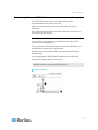
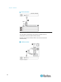
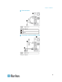
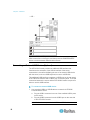
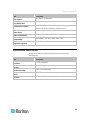
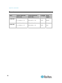
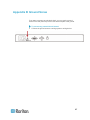
Raritan LED KVM Console (T1700-LED/T1900-LED) User Guide Release 1.1 Copyright © 2014 Raritan, Inc. T1700LED_T1900LED-0B-v1.1-E July 2014 255-37-0002-00 RoHS This document contains proprietary information that is protected by copyright. All rights reserved. No part of this document may be photocopied, reproduced, or translated into another language without express prior written consent of Raritan, Inc. © Copyright 2014 Raritan, Inc. All third-party software and hardware mentioned in this document are registered trademarks or trademarks of and are the property of their respective holders. FCC Information This equipment has been tested and found to comply with the limits for a Class A digital device, pursuant to Part 15 of the FCC Rules. These limits are designed to provide reasonable protection against harmful interference in a commercial installation. This equipment generates, uses, and can radiate radio frequency energy and if not installed and used in accordance with the instructions, may cause harmful interference to radio communications. Operation of this equipment in a residential environment may cause harmful interference. VCCI Information (Japan) Raritan is not responsible for damage to this product resulting from accident, disaster, misuse, abuse, non-Raritan modification of the product, or other events outside of Raritan's reasonable control or not arising under normal operating conditions. If a power cable is included with this product, it must be used exclusively for this product. Contents Important Safeguards v What the Warranty Does Not Cover .............................................................................................. v Safety Instructions ........................................................................................................................ vi Chapter 1 Introduction 1 Package Content ........................................................................................................................... 1 Structure Diagram.......................................................................................................................... 2 Chapter 2 Installation 3 Before Installation .......................................................................................................................... 3 Installing the LED KVM Console.................................................................................................... 4 Connecting a Server or KVM Switch ............................................................................................. 7 Connection to a KVM Switch ............................................................................................... 7 Connection to a Server........................................................................................................ 8 Connecting an External USB Device (Optional) .......................................................................... 10 Chapter 3 Operation 12 Locking or Unlocking the LED KVM Console .............................................................................. 12 Operating the LED KVM Console ................................................................................................ 13 Closing the LED KVM Console....................................................................................................14 Chapter 4 Using the OSD Menu 15 Onscreen Display Operation........................................................................................................ 15 Onscreen Menu ........................................................................................................................... 16 Auto Adjust ........................................................................................................................ 16 Luminance ......................................................................................................................... 17 Management...................................................................................................................... 17 Color .................................................................................................................................. 18 OSD ................................................................................................................................... 19 Language........................................................................................................................... 19 Recall................................................................................................................................. 20 Information......................................................................................................................... 20 iii Contents Selecting the Video Source (Optional)......................................................................................... 21 Appendix A Specifications 22 Technical Specifications .............................................................................................................. 22 T1700-LED ........................................................................................................................ 22 T1900-LED ........................................................................................................................ 24 Environmental Specifications....................................................................................................... 25 Dimensions .................................................................................................................................. 26 Appendix B Ground Screw iv 27 Important Safeguards Read all these instructions carefully before you use the device. Save this manual for future reference. What the Warranty Does Not Cover Any product, on which the serial number has been defaced, modified or removed. Damage, deterioration or malfunction resulting from: Accident, misuse, neglect, fire, water, lightning, or other acts of nature, unauthorized product modification, or failure to follow instructions supplied with the product. Repair or attempted repair by anyone not authorized by us. Any damage of the product due to shipment. Removal or installation of the product. Causes external to the product, such as electric power fluctuation or failure. Use of supplies or parts not meeting our specifications. Normal wear and tear. Any other causes which does not relate to a product defect. Removal, installation, and set-up service charges. v Chapter 1: Important Safeguards Safety Instructions vi Unplug equipment before cleaning. Don't use liquid or spray detergent; use a moist cloth. Keep equipment away from excessive humidity and heat. Preferably, keep it in an air-conditioned environment with temperatures not exceeding 40º Celsius (104º Fahrenheit). When installing, place the equipment on a sturdy, level surface to prevent it from accidentally falling and causing damage to other equipment or injury to persons nearby. When the LCD console is in an open position, do not cover, block or in any way obstruct the gap between it and the power supply. Proper air convection is necessary to keep it from overheating. Arrange the equipment's power cord in such a way that others won't trip or fall over it. If you are using a power cord that didn't ship with the equipment, ensure that it is rated for the voltage and current labeled on the equipment's electrical ratings label. The voltage rating on the cord should be higher than the one listed on the equipment's ratings label. Observe all precautions and warnings attached to the equipment. If you don't intend to use the equipment for a long time, disconnect it from the power outlet to prevent being damaged by transient overvoltage. Keep all liquids away from the equipment to minimize the risk of accidental spillage. Liquid spilled on to the power supply or on other hardware may cause damage, fire or electrical shock. Only qualified service personnel should open the chassis. Opening it yourself could irreparably damage the equipment and invalidate its warranty. If any part of the equipment becomes damaged or stops functioning, have it checked by qualified service personnel. Chapter 1 Introduction This User Guide introduces Raritan's 1U rackmount LED KVM Consoles: T1700-LED and T1900-LED, which are used to operate a KVM switch or server in the data center or server room. A Raritan LED KVM Console features an LED-backlit LCD display and a DVI port. T1700-LED and T1900-LED are functionally identical except for the following major differences: T1700-LED uses a 17-inch display while T1900-LED uses a 19-inch display. T1700-LED supports the video resolution up to 1920 x 1080 while T1900-LED supports up to 1280 x 1024. T1700-LED's screen aspect ratio is 16:9 while T1900-LED's is 4:3. For more details, see Technical Specifications (on page 22). In This Chapter Package Content .......................................................................................1 Structure Diagram .....................................................................................2 Package Content The LED KVM Console comes with standard parts shown below. Check and make sure they are included and in good condition. If anything is missing or damaged, contact Raritan or the local vendor immediately. LED KVM Console Rackmount brackets * Mounting depth adjustable from 520 to 902 mm KVM combo cable (VGA, USB, PS/2) DVI cable Quick Setup Guide Warranty card Power cord Drawer key (to unlock the console) 1 Chapter 1: Introduction Structure Diagram 1. Touchpad 2. Keyboard 3. Indicators for Num Lock, Caps Lock and Scroll Lock status 4. LCD display 5. OSD buttons and indicator lamp 6. Adjustable mounting brackets 7. Ergonomic concave handle 8. Lock 2 Chapter 2 Installation In This Chapter Before Installation......................................................................................3 Installing the LED KVM Console ...............................................................4 Connecting a Server or KVM Switch .........................................................7 Connecting an External USB Device (Optional)......................................10 Before Installation It is very important to locate this product in a suitable environment. The surface for placing and fixing this product should be stable and level or mounted into a suitable cabinet. Make sure the place has good ventilation, is out of direct sunlight, away from sources of excessive dust, dirt, heat, water, moisture, and vibration. Convenience for connecting this product to the related facilities should be well considered too. 3 Chapter 2: Installation Installing the LED KVM Console Follow the procedure below to install the LED KVM Console. To rack-mount the LED KVM Console: 1. Slightly loosen the fasteners on the brackets, adjust the length of the brackets to match the mounting depth of the rack, and then tighten the fasteners. 4 Chapter 2: Installation 2. Fastens the brackets to the rack rails securely with your own screws or cage nuts. 3. Slide the LED KVM Console between the brackets as shown below. 5 Chapter 2: Installation 4. Fasten the LED KVM Console to the rack. The diagram below illustrates how the LED KVM Console moves between the brackets. 6 Chapter 2: Installation Connecting a Server or KVM Switch The LED KVM Console can be connected to either a KVM (keyboard/video/mouse) switch or a server. Always use the Raritan-provided KVM combo cable to make the connection. A DVI cable is also required if the server's video port is a DVI port or if you prefer using the DVI port. Connection to a KVM Switch You can make a connection to any KVM Switch via a USB or PS/2 connection as illustrated below. Then use Raritan's LED KVM Console to access the KVM Switch and the equipment connected to the KVM Switch. Do NOT connect both USB and PS/2 connectors to the KVM switch simultaneously. If connecting Raritan's MCCAT28/216 KVM Switch, the LED KVM Console only supports the PS/2 connection. Warning: Raritan's MasterConsole II (MCC) KVM switch is NOT supported so do not connect any MCC device to it. USB connection 7 Chapter 2: Installation PS/2 connection KVM combo cable KVM switch Connection to a Server You can make a connection to any server via USB, PS/2 or a combination of DVI and USB or PS/2 interface. Do NOT connect both USB and PS/2 connectors to the server simultaneously. USB connection 8 Chapter 2: Installation PS/2 connection KVM combo cable Server Connections via DVI and USB or PS/2 9 Chapter 2: Installation -- OR -- KVM combo cable DVI cable Server Tip: If both DVI and VGA ports are available on the server, you may make connections to both ports, and then press the DOWN/SOURCE button to switch between different video sources. Connecting an External USB Device (Optional) The LED KVM Console provides an additional USB interface that functions as the extension of the USB-A interface of the server connected to it, therefore facilitating the use of an external USB device with the server, such as a USB keyboard, mouse or a USB disk. This additional USB interface comprises a USB-B port on the rear panel of the LED KVM Console and a USB-A port on the front panel. The USB connection between the server and the LED KVM Console is required in order to use this USB interface. To connect an external USB device: 1. Use a regular USB-A to USB-B cable to connect the LED KVM Console and the server. a. Plug the USB-A connector into one of the available USB-A ports on the server. b. Plug the USB-B connector into the USB-B port on the rear side of the LED KVM Console. Note: Raritan does not provide the USB-A to USB-B cable. 10 Chapter 2: Installation 2. Connect any USB device to the front panel USB-A port of the LED KVM Console. Now the server should detect the connection of this external USB device. If necessary, install the driver for the detected USB device. 11 Chapter 3 Operation In This Chapter Locking or Unlocking the LED KVM Console ..........................................12 Operating the LED KVM Console............................................................13 Closing the LED KVM Console ...............................................................14 Locking or Unlocking the LED KVM Console The LED KVM Console has a lock to the right side. When locked, you cannot draw this product out of the rack. Use the drawer key or a coin-shaped object to turn the lock. To unlock this product, turn the lock counterclockwise. To lock this product, turn the lock clockwise. 12 Chapter 3: Operation Operating the LED KVM Console 1. Gently pull the concave handle toward the front of the LCD display. 2. Flip up the LCD display to a suitable angle. 3. Operate the LED KVM Console. For information on LCD buttons and onscreen menu, see Using the OSD Menu (on page 15). 13 Chapter 3: Operation Closing the LED KVM Console 1. Locate a gray-arrow release button on two sides of the LED KVM Console. 2. Push both gray-arrow buttons in the direction as indicated by the arrow head before pushing the LED KVM Console into the rack. 3. Keep pushing the gray-arrow buttons until this product is completely moved into the rack. 14 Chapter 4 Using the OSD Menu You can customize the video properties of the built-in LCD display, such as colors and image position, and the OSD settings, such as the language displayed in the OSD, by changing the settings of the OSD menu. In This Chapter Onscreen Display Operation ...................................................................15 Onscreen Menu .......................................................................................16 Selecting the Video Source (Optional) ....................................................21 Onscreen Display Operation Buttons Function POWER Power on/off the LCD panel. The LCD indicator lamp indicates the current power on/off status. Light off = LCD power off Blue = LCD power on 15 Chapter 4: Using the OSD Menu Buttons Function UP/AUTO This button has two functions: When no OSD is displayed, pressing this button optimizes the visual settings. While the OSD is being displayed, pressing this button moves up the selection. DOWN/SOURCE This button has two functions: MENU EXIT When no OSD is displayed, this button is used to select the video source - VGA or DVI. While the OSD is being displayed, pressing this button moves down the selection. This button has two functions: When no OSD is displayed, pressing this button triggers the OSD menu. While the OSD is being displayed, this button functions as the Enter key and can be used to confirm the selection. Quit the current OSD setting page or the OSD menu. Onscreen Menu The onscreen menu contains eight items: four are related to the visual quality, two are related to the OSD settings, one is to show the current video information, and one is used to restore the settings to factory defaults. Auto Adjust 16 Chapter 4: Using the OSD Menu Auto Adjust: Fine tune the video signals to eliminate waviness and distortion. An "Auto Adjusting" message is displayed during the process. Luminance Brightness: Make the screen image brighter or darker. Contrast: Adjust the difference between the background black level and foreground white level. Black Level: Adjust the black level of the screen image. Sharpness: Fine tune the sharpness of the screen image. Management H. Position: Move the screen image left or right. 17 Chapter 4: Using the OSD Menu V. Position: Move the screen image up or down. Pixel Clock: Adjust the clock/pitch to synchronize the sampling clock of the LCD with the pixel clock of the connected equipment. This adjustment is needed only for VGA signals when Auto Tune does not get the optimum video performance and vertical dark bands are visible on the screen. Phase: Adjust the phase to synchronize the frequency settings of the LCD with the frequency output of the connected equipment. Perform this adjustment only when horizontal streaking is seen on the screen. Color Select the screen color temperatures. The factory default is 6500K. 9300: Add blue to the screen image, making the white cooler. 6500: Add red to the screen image, making the white warmer. 5400: Add green to the screen image, making the white cooler. User Preset: Adjust red, green and blue colors respectively. 18 Chapter 4: Using the OSD Menu OSD H. Position: Adjust the OSD's horizontal position. V. Position: Adjust the OSD's vertical position. OSD Time: Set the time duration in seconds for which the OSD remains visible after the last button is pressed. The factory default is 10 seconds. Language Select the language in which the OSD menu is displayed. Available options include English, Chinese, Japanese, Deutsch, Français, Español, Italiano, Korean, Portuguese and Russian. 19 Chapter 4: Using the OSD Menu Recall Recall Color: Reset all colors to factory defaults. Recall All: Reset all settings to factory defaults except for the language setting. A confirmation message appears after selecting either Recall option. Press UP/AUTO to select Yes and then press MENU to confirm the operation. Information Display Information: Display the current resolution and frequency information on the screen. 20 Chapter 4: Using the OSD Menu Selecting the Video Source (Optional) If both VGA and DVI ports are available on the server, you can make connections to both ports through the 3-in-1 and DVI cables respectively. When both video ports are used, you can switch between these two video sources by operating the OSD. To switch between VGA or DVI signals: 1. Press the DOWN/SOURCE button on the LCD panel. An OSD appears, showing two options - VGA and DVI. 2. Press the UP/AUTO or DOWN/SOURCE button to select a video source. 3. Press MENU to confirm your selection. 21 Appendix A Specifications In This Chapter Technical Specifications ..........................................................................22 Environmental Specifications ..................................................................25 Dimensions ..............................................................................................26 Technical Specifications T1700-LED Item Form factor Diagonal size Screen aspect ratio Max. resolution Brightness (cd/m²) Color support Contrast ratio (typ.) Viewing angle (H/V) Display area (mm) Response time (ms) Resolution Description 1U rack mounting on slide-out rails 17.3" TFT 16:9 1920 x 1080 300 16.7M 650:1 70° x 70° 337 x 270 2 720 x 400, 70Hz (IBM VGA) 640 x 480, 60Hz (IBM VGA) 640 x 480, 72 / 75Hz (VESA) 800 x 600, 56 / 60 / 72 / 75Hz (VESA) 1024 x 768, 60 / 70 / 75Hz (VESA) 1152 x 864, 75Hz (VESA STD) 1280 x 1024, 60 /70Hz (VESA STD) 1280 x 1024, 75Hz (VESA) 22 Appendix A: Specifications Item Description 1440 x 900, 60 / 75Hz (VESA STD) 1680 x 1050, 60Hz (VESA STD) 1920 X 1080, 60Hz (VESA STD) DDC support Plug & play DDC Console port (combo) Power input Power consumption Compatibility Regulation approval DDC, DDC2, and DDC2B EDID 1.3 3-in-1 DB-15 connector for VGA / keyboard / mouse Support USB & PS/2 servers or KVM switches Auto-sensing 100 to 240VAC, 50 / 60Hz Max. 12.2 Watt, Standby 3.2 Watt Multi-platform - Mix PCs, SUNs, IBMs, HPs FCC, CE, UL, VCCI and RoHS 23 Appendix A: Specifications T1900-LED Item Form factor Diagonal size Screen aspect ratio Max. resolution Brightness (cd/m²) Color support Contrast ratio (typ.) Viewing angle (H/V) Display area (mm) Response time (ms) Resolution Description 1U rack mounting on slide-out rails 19" TFT 4:3 1280 x 1024 250 16.7M 1000:1 80° x 80° 376 x 301 5 640 x 350, 70Hz 640 x 400, 70Hz 640 x 480, 60Hz (IBM VGA) 640 x 480, 72 / 75Hz (VESA) 720 x 400, 70Hz (IBM VGA) 800 x 600, 56 / 60 / 72 / 75Hz (VESA) 1024 x 768, 60 / 70 / 75Hz (VESA) 1280 x 1024, 60 / 70 Hz (VESA STD) 1280 x 1024, 75Hz (VESA) 24 Appendix A: Specifications Item DDC support Plug & play DDC Console port (combo) Power input Power consumption Compatibility Regulation approval Description DDC, DDC2, and DDC2B EDID 1.3 3-in-1 DB-15 connector for VGA / keyboard / mouse Support USB & PS/2 servers or KVM switches Auto-sensing 100 to 240VAC, 50 / 60Hz Max. 16.2 Watt, Standby 3.6 Watt Multi-platform - Mix PCs, SUNs, IBMs, HPs FCC, CE, UL, VCCI and RoHS Environmental Specifications All LED KVM Console models share the same environmental specifications. Item Operation Storage Relative humidity Shock Vibration Description 0° to 40°C degrees -5° to 60°C degrees 5~90%, non-condensing 10G acceleration (11ms duration) 5~500Hz 1G RMS random vibration 25 Appendix A: Specifications Dimensions Model T1700-LED T1900-LED 26 Product dimension (W x D x H) 434 x 569 x 43.5 mm Packing dimension (W x D x H) 742 x 602 x 178 mm Net weight 16 kg Gross weight 17.6 kg 17.1 x 22.4 x 1.71" 29.2 x 23.7 x 7.0" 35.3 lb 38.8 lb 434 x 569 x 43.5 mm 750 x 615 x 185 mm 17 kg 18.6 kg 17.1 x 22.4 x 1.71" 29.5 x 24.2 x 7.3" 37.5 lb 41 lb Appendix B Ground Screw If you want to prevent any electrical shock, you can use the ground screw on the rear panel to provide a safe electrical path to the ground. To prevent any potential shock hazard: Connect the ground screw to a wiring system or wiring device. 27