1
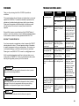
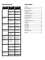
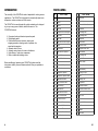
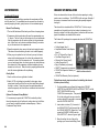
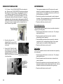
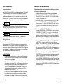
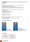
Operation Manual
COOL IT1000
®
®
7,500 BTU Portable Air Conditioner
AirPac, Incorporated
AirPac Technology Park
888 Shenandoah Shores Road
Front Royal, Virginia 22630
U.S.A.
Instructions for Installation,
Operation & Maintenance
Toll Free 888-324-7722
Web: airpacinc.com
email: [email protected]
The Coolest Site on the Web ®
© 1999 AirPac, Incorporated
Printed in U.S.A.
Manual CIT119..INSTR
airpacinc.com
UNIT WARRANTY
IMPORTANT — READ BEFORE YOU PROCEED
AirPac warrants to its authorized distributor, each new COOLIT1000 to
be free from defects in material and workmanship for a period of one (1)
year from date of purchase.
When you receive your COOLIT1000 shipment unpack the unit box by
slipping the bands off the box — do not cut the bands.
KEEP ALL ORIGINAL PACKAGING MATERIAL.
Limitations: This warranty shall not apply to nor include any of the
following:
ORIGINAL PACKAGING MATERIAL IS REQUIRED
WHEN RETURNING ANY UNIT DAMAGED IN SHIPPING.
1. Any repair or replacement required as a result of accident, misuse,
lack of proper maintenance, incorrect wiring, repairs improperly
performed or replacements improperly installed by any person, or
use of a replacement part or accessory not conforming to
specifications of AirPac.
2. Any repair or replacement required as a result of normal wear and
tear.
3. Any consequential, incidental, special, or exemplary damages.
4. Replacement of belts, pulleys, and filters.
5. Any unit which has its serial numbers altered, defaced or removed.
The sole obligation of AirPac under this warranty will be to furnish,
without charge, a replacement part for a defective part. This warranty
does not include installation, transportation, or postage costs
associated with installing the replacement part.
In order for this warranty to become effective, the warranty registration
card, delivered with the unit, must be completed and returned to AirPac
within 30 days of purchase and delivery. Any claim under this warranty
should be first presented to and processed by the authorized distributor
from whom the equipment was purchased.
To the extent permitted by law, this warranty is expressly in lieu of any
other warranties, either expressed or implied, made by AirPac,
Incorporated. AirPac assumes no liability in any event for lost profits, or
any consequential damages of any kind arising from breach of this
warranty.
30
Inspect all shipping cartons for visible shipping damage. You must
document damage with the shipper. Call your COOLIT1000 Dealer
immediately to report shipping damage. Your COOLIT1000 Dealer will
advise you how to proceed with the shipping claim.
FORWARD
Thank you for purchasing the AirPac COOLIT1000 portable air
conditioner.
This manual describes the unit features and explains how to set-up and
operate the COOLIT1000. Preventative maintenance procedures are
outlined and a trouble-shooting guide is provi ded for your reference.
Please read this operation manual thoroughly to familiarize yourself
with the features of the unit and to ensure years of trouble-free
operation.
TROUBLE SHOOTING GUIDE
PROBLEM
Unit making noise
CAUSE
Unit is not level.
Make sure operating
surface is level.
Water draining into
tank.
This is normal.
The exhaust hose is
broken
Sometimes the hose
comes in 2 different
pieces.
Extend the last thread
on each piece of hose,
thread right on top of
the other until they are
both tight and come
together to form one
whole piece.
There is a black plug
right above the condensate tank
The plug belongs
there during normal
operation.
Remove plug to drain
water before storage
or transport of unit.
We would like to ensure your satisfaction with the COOLIT family of
products. If you have questions or require additional information please
do not hesitate to contact our factory personnel at 888-324-7722.
WE WANT TO HEAR FROM YOU
If you have comments or suggestions on how to improve this COOLIT
manual please let us know. Our most important source of information
for product improvement is from our customer base. We count on you
to continually challenge us at AirPac to build a better air conditioner.
Please give us a call, 888-324-7722 or email us, [email protected].
AirPac’s marketing department would love to hear just what you are
cooling with your COOLIT1000. Send us a short narrative and a picture
and we just may publish your story on AirPac’s web site.
Unit is making noise at The fan may be hitting Unit requires repair or
the evaporator fan.
the foam housing.
replacement
Unit is making noise at The fan may be hitting Unit requires repair or
the condenser fan.
the foam housing.
replacement.
Unit is making noise
The coil in the flash
above the condensate pan is hitting the unit.
tank.
When the unit is
cooled down, remove
the flash pan by removing the 5 screws
that hold the flash
pan. Pull the coil
away from the unit.
Replace the flash pan
with the 5 screws.
LED window displays
number that is not between 60° and 90° F.
Faulty control board.
Board needs to be replaced.
Unit works but is not
cooling the room
enough.
The BTU load in the
room is greater than
7,500 BTU.
Need more cooling.
Add another COOLIT.
WARNING:
Describes precautions that should be observed in order to prevent
injury to the user during installation
CAUTION:
Describes precautions that should be observed in order to prevent
damage to the unit or its components, which may occur during
installation or unit operation if proper care is not exercised.
NOTE:
SOLUTION
Provides additional information that facilitates unit operation.
29
TROUBLE SHOOTING GUIDE
PROBLEM
Unit does not work
Poor cooling
performance
CAUSE
TABLE OF CONTENTS
SOLUTION
Unit not plugged in.
Plug in power cord.
Main power off.
Check fuse or circuit
breaker.
Water tank full.
Empty water tank.
Wrong function mode
selected.
Set in correct function
mode.
Condenser air exhaust Clear all objects from
or intake blocked.
air grills, move away
from wall.
Unit operates but is
not cooling
Compressor has not
yet started.
Wait 3 minutes for
time delay to elapse.
Temperature selection Decrease temperature
incorrectly set.
setting.
Compressor stops
running after a short
time
Voltage is insufficient.
Unit operates with no
switches or lights
functioning.
Unit has been turned
on/off repeatedly from
the control panel.
Turn unit off, remove
plug from outlet. Restart after 3 minutes.
Compressor runs
when unit set on fan
mode.
Temporary malfunction with internal
circuitry memory.
Turn off unit at I/O
control. Restart unit
and immediately
change to fan mode.
Water is leaking
Drain tube clogged.
Remove blockage.
Water tank improperly
seated.
Reposition tank.
Damaged water tank.
Replace tank.
Water tank is full.
Empty the tank.
Power failure.
Check plug and fuses.
Unit unexpectedly
stops operating
28
Correct input power.
Unit is plugged into an Remove extension
extension cord.
cord.
Introduction .............................................................................. 6
Equipment Check List ............................................................. 7
Inspection of Equipment ......................................................... 8
Unit Overview ........................................................................... 9
Preparing Unit for Operation .................................................10
Exhaust Kit Installation .........................................................13
Control Panel Functions ........................................................16
Unit Operation ........................................................................18
Condensate Pump Installation .............................................21
Maintenance ..........................................................................23
Specifications.........................................................................24
Wiring Diagram ......................................................................25
Parts Diagram ........................................................................26
Parts Listing ...........................................................................27
Troubleshooting Guide ..........................................................28
Warranty .................................................................................30
INTRODUCTION
The versatility of the COOLIT1000 makes it adaptable for cooling various
applications. The COOLIT1000 is designed to automatically adjust room
temperature, reduce moisture and filter room air.
The COOLIT1000 is manufactured with quality materials and is designed
to give you many years of reliable, trouble-free service. The
COOLIT1000 features:
T Convenient touch-pad electronic operation panel
T Digital display panel
T Functional buttons and indicators, starting and
stopping operation, selecting mode of operation, fan
speed and temperature
T Automatic shut-off timer
T Automatic swing louvers for even air distribution
T High efficiency, quiet rotary compressor
T Rear air intake and discharge vents
Before installing and operating your COOLIT1000, please read the
instructions carefully to ensure maximum benefit from your portable air
conditioner.
6
PARTS LISTING
#
PART NAME
#
PART NAME
1
Base Pan
31
Float Case
2
Holder 1
32
Float Body
3
Holder 2
33
Microswitch Water Container
4
Drain Pan
34
Condenser
5
Condenser Fan Motor Support
35
Connecting Rod 1
6
Short Plant
36
Connecting Rod 2
7
Long Plate
37
Evaporator
8
Evaporator Fan Motor Support
38
Louver Motor
9
Caster
39
Eccentric Wheel
10
Control Board
40
Evaporator Rear Plate
11
Evaporator Fan Capacitor
41
Grille Vertical
12
Terminal Block
42
Connecting Rod
13
Terminal Block Holder
43
Air Outlet Frame
14
Transformer
44
Senser Holder
15
Condenser Fan Capacitor
45
Ambient Senser
16
Relay Board
46
Pipe Assembly
17
Compressor Capacitor
47
Cooling Coil Pipe
18
Compressor Capacitor Holder
48
Filter
19
Evaporator Fan Motor
49
Capillary Tube
20
Motor Connection Plate
50
Compressor
21
Motor Mounting
51
Overload Protector
22
Evaporator Fan
52
Overload Protector Cover
23
Evaporator Fan Shroud
53
Nut
24
Motor Connection Belt
54
Top Cover
25
Condenser Fan Belt
55
Front Cover
26
Condenser Fan
56
Operation Panel
27
Condenser Fan Shroud
57
Air Filter
28
Condensate Tank
58
Cabinet
29
Microswitch Water Overflow
59
Vent Grille
30
Water Container
27
PARTS DIAGRAM
EQUIPMENT CHECK LIST
The first step in preparing the COOLIT1000 for installation is to run
through this check list to ensure you have all the pieces necessary for
your installation.
Your shipment consists of two boxes:
1. COOLIT1000 Unit Box contains:
COOLIT1000 (Item 1)
2. COOLIT1000 Accessory Box contains:
Ceiling Adapter (Item 2)
Adjustable Window Panel Adapter (Item 3)
8.5’ x 5” Exhaust Duct (Item 4)
Duct Base Flange (Item 5)
Window Duct Flange (Item 6)
Holder Flange (Item 7)
Bag of Fasteners (not pictured)
ADAPT Thermometer (not pictured)
COOLIT1000 Operation Manual (not pictured)
COOLIT1000 Warranty Card (not pictured)
3
4
2
1
5
26
19
6
7
7
INSPECTION OF EQUIPMENT
WIRING DIAGRAM
All COOLIT1000 units are shipped in sturdy packaging reinforced with
foam panels and covered with cardboard cartons. The accessory items
for the standard exhaust kit are shipped in a separate box at the same
time the unit is shipped. Both boxes should arrive together but there is
a possibility that the packages will be separated in shipping. Your
complete shipment consists of two pieces; the unit and a box of
accessory items for the standard exhaust kit.
Upon receipt of the unit and accessory items for the exhaust ducting kit,
inspect it for any visible or concealed damage. Report any damage to
your local AirPac distributor so a damage claim can be processed. It is
very important to keep all packaging for inspection by the shipper. DO
NOT OPERATE UNIT.
CAUTION:
If you have shipping damage keep all packaging for inspection by
the shipper. If equipment requires return to your AirPac distributor a
Call Tag will be issued and pick up will be arranged by the AirPac
Distributor. DO NOT OPERATE UNIT.
SAFETY PRECAUTIONS
The instructions stated in this booklet are written for the user’s safety
and must be followed closely. Use of this unit in any other manner may
create a hazard for the user and others nearby. Failure to follow these
instructions may damage unit and void the warranty.
AIRPAC
Description: COOLIT1000
PART#: DIA -201
DATE: 04/01/99
APPROVED BY: MJS
8
25
UNIT SPECIFICATIONS
UNIT OVERVIEW
COOLIT1000 Technical Specifications
Cooling Capacity
7,500 BTU/h
Power Source
115 V 60 HZ
Rated Current
8.5 Amps
Power Input
950 Watts
Compressor Type
Air Flow
Rotary
Supply Air Vent
Control Panel
Oscillating
Vertical Grill
Adjustable
Horizontal
Louvers
Evaporator
Return
100 Low / 180 Hi CFM
Dehumidifier Value
Sound Level
.26 gal/hour
52 dB
Physical Dimensions
14”W x 14.5”D x 29.7”H
Net Weight
80 lbs
Shipping Weight
88 lbs
FRONT VIEW
Condensate
Water Tank
(behind door)
REAR VIEW
Condenser
Air Intake
Power
Cord
Condenser
Air Discharge
COOLIT 1000 cooling a small LAN
and Telecommunications closet.
Casters
24
9
PREPARING UNIT FOR OPERATION
UNIT MAINTENANCE
Your new COOLIT1000 unit has passed a double quality assurance
program; once before leaving the factory and again before leaving the
regional warehouse. If you find shipping damage please contact the
point of purchase immediately. DO NOT OPERATE THE UNIT.
Your COOLIT1000 is designed for easy maintenance. Performing
routine preventive maintenance will ensure you enjoy years of troublefree operation and keep your unit running at peak efficiency.
IMPORTANT: After unpacking your unit and inspecting to ensure unit is
in good condition, place unit upright for a minimum of two hours before
operating. Otherwise you may damage the unit and void your warranty.
To further prepare the unit for operation proceed as follows:
START UP PROCEDURE
CAUTION:
Before any maintenance make sure the unit has stopped running and
unplug the unit from the electrical outlet.
Air Filter
The air filter will accumulate dust and dirt when operating in the cooling
and dehumidifying functions. It is important to keep the filter clean so
the air flow in not restricted and cooling is optimized. To clean filter:
The unit is designed for indoor use only. For the cooling mode the
temperature range for operation is 60° F to 90° F.
1. Open the condensate water tank door and
remove filter by pulling down, see figure at
right.
1. Unpack COOLIT 1000 and COOLIT Accessory Box.
2. Clean with vacuum cleaner or wash with a
neutral detergent and warm water. Air dry
filter.
Unpack and inspect the unit and items in the accessory box to
ensure unit and all parts are in good condition.
2. Place COOLIT 1000 unit upright.
Keep unit in upright position for a minimum of two hours before
operating.
3. Place the unit on a flat, solid surface.
Operation on uneven surfaces may cause vibration, noise and
possible water leakage from condensate tank.
4. Check that the condensate water tank is in place and
properly seated.
If the condensate tank is not installed properly the unit will not
operate. The unit will automatically turn off when the tank is full.
5. Check that all air filters are clean and properly
installed.
To maintain efficiency and avoid damage to the unit, never operate
the unit without the air filters installed in the proper direction. Filter
should be installed with “front” mark facing outwards.
10
3. Reinsert the filter with the “FRONT” mark
on the filter facing outwards.
Cabinet Maintenance
To clean the surface of the cabinet use warm
water and a neutral, non-abrasive detergent.
Ensure all detergent is wiped from the surface
and rinse with clear water so there is no
detergent residue on the cabinet.
COOLIT 1000 Filter
CAUTION:
DO NOT clean the surface with thinners, alcohol, polishing powder,
alkaline detergent, acid or an abrasive brush. Using these items
could scratch and damage the cabinet.
Condensate Water Tank
The interior of the tank should be cleaned to avoid growth of mold and
mildew. Flush the tank with a solution of warm water and mild
detergent.
Remove the black plug from the left drain tube to drain the condensate
around the base of the evaporator coil before transporting or storing the
COOLIT1000. Replace plug into the left drain tube before operating unit.
23
CONDENSATE PUMP KIT - Optional Accessory
6. Read instructions packed with the pump for piping the discharge
line.
7. The pump supplied with your COOLIT1000 unit may have two
wires coming from the top of the pump. These wires are low voltage safety switch leads and are not used for normal operation of
your COOLIT1000. If you would like to use the safety switch leads
for connecting to an alarm you must consult the instructions supplied with the condensate pump kit.
8. Place the pump behind the COOLIT1000 unit. Be sure that neither
hose is crimped.
9. Plug in the COOLIT1000 and the condensate pump.
10. Test the pump operation. Make sure there is power to the
COOLIT1000 and the condensate pump. Fill the reservoir with
water and when the water reaches the full level the impeller will
activate and the water will be pumped from the reservoir into the
condensate drain line tubing.
To remove condensate pump option reverse the above
instructions.
NOTE:
Read and follow all instructions enclosed with the pump before
operating the unit. For maintenance tips refer to the pump
instructions.
PREPARING UNIT FOR OPERATION
6. Plug COOLIT 1000 unit into wall outlet.
Plug unit into wall outlet. Do not plug COOLIT1000 into extension
cord, surge protector, or uninterruptable power supply. You will
hear the unit beep and two red dashes (- -) will be displayed in the
LED window on the control panel.
7. Turn the COOLIT 1000 unit on.
To turn the unit on press the I/O button on the control panel. The
unit will blow air from the front grills to the left of the control panel.
The condenser air is discharged through the exhaust grill located on
the back of the unit. There is also an indicator light that shows the
mode and speed. In the LED display window on the control panel
you will see a two digit number which indicates the room
temperature — the room temperature reading will take several
minutes to adjust and reflect a true reading.
8. Set the desired function mode and fan speed.
You may select from three different modes of operation by pushing
the function mode button; cool, dehumidify, and fan. The indicator
light next to the appropriate symbol will illuminate when that
function is selected. Once your desired function mode is selected
(cool, dehumidify or fan), the fan speed is set by pushing the fan
speed button. The light next to the selected function symbol will be
red which indicates high fan speed. Push the fan speed button
again, a green light indicates low fan speed. High fan speed is not
available in dehumidifying mode, only low fan speed is available.
9. Set the desired temperature.
To set the temperature you must press the timer/thermometer
button until the green indicator light for the thermometer is blinking.
Adjust your desired temperature set point by pressing the up and
down arrows. Once the desired temperature is set (range is from
60°F to 90°F) wait until the thermometer indicator stops blinking and
the room temperature is displayed in the LED window, or you may
press the timer/thermometer button twice to return to the standard
room temperature display.
10. Set the timer (OPTIONAL).
You may set the timer, which controls the operation of the
COOLIT1000, for from 1 to 12 hours in one hour increments. The
22
11
PREPARING UNIT FOR OPERATION
COOLIT1000 will shut off after the unit has been operating for the
designated number of hours on the timer. To set the timer press
the timer/thermometer button twice until the timer indicator light is
flashing green. Press the up and down arrow buttons to select the
desired number of hours (from 1—12 hours). Once you have set
the desired time wait until the timer indicator stops blinking and the
standard display of the room temperature will be in the LED window
on the control panel, or you may press the timer/thermometer
button once to return to the standard display. When your timer is
set the timer indicator light will be steady green.
11. Set up the condensate pump (OPTIONAL).
To install the condensate pump for continual automatic removal of
condensate refer to the Condensate Pump Kit instructions on page
21 of this manual.
12. Shut off the COOLIT 1000.
To shut down the COOLIT1000 just press the I/O button and the unit
will shut off. Since the unit is still plugged into the wall outlet there
will be two red dashes (- -) displayed in the LED window on the
control panel. This is normal and indicates that there is power to
your unit.
WARNING:
To reduce risk of fire or electric shock do not expose unit to rain or
moisture. Do not open cabinet while unit is connected to a power
source. Dangerous voltage is present. Have repairs performed by
certified HVAC technicians.
CONDENSATE PUMP KIT - Optional Accessory
This pump kit is an optional accessory for the COOLIT1000. The
condensate pump kit is useful when the COOLIT1000 must be operated
continuously and the condensate tank cannot be emptied and a gravity
drain line is impractical. Follow the easy steps for installing and using
the Condensate Pump Kit, part number CPKIT-1000.
1. Turn off the unit and unplug from wall
outlet.
2. Remove the condensate water tank
located behind the bottom front panel,
see figure at right.
3. Locate the tank microswitch in the water
tank compartment. (The bottom switch).
Carefully remove the the slip-on quick
connector from the 2nd terminal on the
switch and place the slip-on quick
connect on the 1st terminal position.
4. Push out the knockout on the right side of Condensate Tank
the water tank compartment by turning the knockout back and
forth. Cut a 36” piece of the 3/8” ID vinyl tubing (25’ included in
condensate pump box) and feed the tube through the knockout
hole and push onto the drain connection of the unit. Make sure
you connect to the right drain connection and not the plugged left
connection. Do not remove the plug from the left drain tube. This
is for draining the unit for shipping and storage.
NOTE:
DO NOT remove the black plug from the left drain tube when
operating the COOLIT1000. This plug maintains a set water level
around the bottom of the evaporator coil. Remove the plug to drain
the water when you need to transport/ship your COOLIT1000 or if
you will be storing your unit for an extended period of time.
5. Place the other end of the tube into condensate pump - the large
hole. Attach additional 3/8” ID vinyl tubing of the appropriate
length to the discharge adapter (barbed connector) of the
condensate pump. You may require more tubing than what is
supplied with the condensate pump. You can either attach the
new section of tubing to the supplied tubing with a coupler or purchase a new section of tubing to fit the required length of your
condensate drain line.
12
21
UNIT OPERATION
DUCT KIT INSTALLATION
EXHAUST
KIT INSTALLATION
Condensate Removal
Warm air is
exhausts
exhausted
fromfrom
the the
rearrear
of the
of the
unitunit
when
when
operating
operating
in cooling
in
coolingasmode
mode
an airasconditioner.
an air conditioner.
The COOLIT
The COOLIT
1000 will cool
will cool
more
more
efficiently if
efficiently
the
warm air
if the
is removed
warm air from
is removed
the area
from
using
thethe
area
specially
using the
designed
specially
designed
ducting
kit.ducting kit.
During cooling and dehumidifying operations the condensate will flow
into the water tank. The condensate can be removed from the tank by
manually emptying the tank, gravity drain or with a condensate pump.
Manual Tank Draining
1. Th e tank full indicator will flash and you will hear a beeping alarm.
2. Compressor will stop and alarm will sound for approximately one
(1) minute. The fan in the unit will continue to run and condensate
from the evaporator coil will continue to flow into the condensate
tank. Allow fan to run for about an additional three (3) minutes to
dry out the moisture in the evaporator coil.
3. Open the water tank door, remove the tank and empty the water.
The alarm will sound indicating the tank is not installed properly.
4. When you go to replace the tank in the unit you may find some
water on the bottom base pan, this is from the condensate that
continued to drain off of the evaporator coil. To properly maintain
your unit and keep it clean, be sure to wipe up any water that may
have drained off of the evaporator coil before replacing the condensate tank in the unit. When the tank is properly positioned the
tank full indicator light/alarm will stop flashing.
Gravity Drain
1. Knock out hole on lower right side of cabinet.
2. Attach 3/8” ID vinyl tubing (not provided) to drain pipe, where
water drains from the unit into the tank, and install tubing through
the hole in cabinet. Drain tubing must be angled downward so
water flows properly into floor drain or condensate line below level
of the unit.
Optional Condensate Pump Method
If it is necessary to operate the COOLIT1000 continually without
threat of automatic shut-off and loss of cooling when tank is full then
you will need to install the optional condensate pump. Refer to
Condensate Pump Section.
20
The exhaust kit
ducting
is standard
kit is standard
with the with
COOLIT
the COOLIT.
1000. TheThe
kit isducting
easy tokit is
easy to assemble
assemble
and is typically
and intall
used
andtocan
duct
beexhaust
used for(condenser)
ducting exhaust
air out
(condenser)
through
a window
air outorthrough
into theaceiling
window
plenum.
or into Instructions
the ceiling plenum.
for theseFollow
two
these of
types
step-by
installations
-step instructions
are detailed
forininstalling
this section.
the ducting kit.
The
1. Exhaust
RemoveKit
theistwo
packaged
metal panels
in a separate
and thebox
screws
from supplied
the COOLIT
with1000
the
unit. ItPANEL
consistsKIT.
of: The PANEL KIT is packaged along side the unit in
the unit box. Slide the smaller panel into the larger and adjust the
2
1 or the
• Ceiling
panel
Adapter
to fit the
(Item
24” 1)
length of your ceiling grid
width of your
3
window Window
opening.Panel
UsingAdapter
the screws supplied, tighten down to hold
• Adjustable
the2)panels together.
(Item
• 8.5’
x 5” Exhaust
Duct (Item
3) PANEL.
2. Snap
the HOLDER
into the
5
4
• Duct Base Flange (Item 4)
Ceiling
plenum
Move ceiling tile out of the grid by6
• 3.
Window
Duct
Flangeinstallation:
(Item 5)
pushing
up (Item
on one
• Holder
Flange
6) end and sliding it back about 6 inches. Put the
PANEL
into
the
ceiling
tile grid. Make sure the PANEL is adjusted
• Bag of Fasteners (not pictured)
properly
and
cannot
fall
out. There should be at least 12 - 15” of
• ADAPT Thermometer (not pictured)
open space above the PANEL outlet so exhaust air is not blocked.
• COOLIT1000 Operation Manual (not COOLIT 1000 Exhaust Duct Kit
For permanent installation cut 5” off the ceiling tile so the tile will
pictured)
lay back in the grid. For temporary installations simply slide the
• COOLIT1000 Warranty Card (not pictured)
ceiling tile tight against the PANEL so when the COOLIT and
PANEL are no longer in use you can simply move the ceiling tile
Follow
these
instructions for installing the exhaust
back
intostep-by-step
place.
kit into a plenum ceiling.
Window installation: Open window and place panel in window
1. For
this Lower
installation
youonto
will need
the large
frame.
window
the PANEL
andplastic
make CEILING
sure the PANEL
ADAPTER,
the
HOLDER
FLANGE,
the
EXHAUST
DUCT
fits snugly by adjusting the PANEL width and tightening
theand the
DUCT
BASE
FLANGE
from
the
screws.
COOLIT1000 accessory box. This panel will
4. Screw
endgrid
of the
EXHAUST
fit into the one
ceiling
once
you moveDUCT
the into the EXHAUST
DUCT
existingBASE.
ceiling tile to one side to accommodate the CEILING ADAPTER.
5. Place the EXHAUST DUCT BASE onto the back of the unit by
aligning
the base
over the
of the
2. Insert
about
six inches
(6”) top
of one
endunit
of exhaust opening and
slide
down into DUCT
place. into the round hole in
the EXHAUST
the CEILING ADAPTER. Extend the 6” and
6. Extend the EXHAUST DUCT to meet the HOLDER so the
screw the HOLDER FLANGE onto the
EXHAUST DUCT is as straight as possible with no excess
E XHAUST DUCT, shown in figure at right.
EXHAUST DUCT and mark the length on the EXHAUST DUCT.
CutMove
the EXHAUST
marked and insert it into the
3.
the ceilingDUCT
tile outtoofthe
thelength
grid by
HOLDER.
the end
EXHA
UST
DUCT
into the HOLDER so that 1
pushing
up Pull
on one
and
sliding
it back
or 2 wire spirals are above the threads. This is to ensure 10-12
Holder Flange.
13
DUCT KIT INSTALLATION
EXHAUST
KIT INSTALLATION
UNIT OPERATION
10—12 inches. Put the CEILING ADAPTER into the ceiling tile
grid. Make sure the CEILING ADAPTER is positioned properly in
the ceiling grid and cannot fall out. There should be at least 12—
15” of open space above the CEILING ADAPTER outlet so exhaust air is not blocked. For permanent installation cut 5” off of
the ceiling tile so the tile will lay back in the grid. For temporary
installations simply slide the ceiling tile tight against the CEILING
ADAPTER so when the COOLIT1000 and CEILING ADAPTER are
no longer in use you can simply move the ceiling tile back into
place, as shown in figure below.
The temperature displayed in the LED window on the control
panel is the current room temperature, not the set temperature
you just selected. The compressor will cycle on and off to maintain the temperature you selected.
4. Press the fan symbol on the control panel to select the desired
fan speed. At the high speed setting, a red light will be illuminated
and at the low speed the light will be green.
5. Press the on/off button to turn the unit off.
Dehumidifying Function
The dehumidifying mode of operation does not need the exhaust duct
required by the cooling mode.
Place Ceiling Adapter
into the ceiling grid.
1. Press the power on/off button to turn the unit on. The cooling indicator light will be red.
2. Press the operation mode button one time to select the
dehumidifying mode of operation.
3. The dehumidifying indicator will show a green light, which indicates that the unit is in dehumidifying mode on low fan speed.
High fan speed is not available in dehumidifying mode.
4. Screw the other end of the
EXHAUST DUCT into the DUCT
BASE FLANGE as shown in the fi gure at right.
4. Press the on/off button to turn the unit off.
5. Place the DUCT BASE FLANGE
onto the back of the unit by aligning
the base beside the unit exhaust
opening and simply slide the DUCT
BASE FLANGE into place, as shown Duct Base Flange connection.
in the figure below.
Connecting Duct
Base Flange to the
back of the condenser air
discharge grill of
the COOLIT1000.
14
Fan Function
The fan mode of operation does not need the exhaust duct required by
the cooling mode.
1. Press the power on/off button to turn the unit on. The cooling indicator light will be red.
2. Press the operation mode button two times to choose the fan
mode of operation.
3. Press the fan speed button to select the desired fan speed. If the
high speed is selected, the fan indicator light will be red. If the low
fan speed is selected the fan indicator shows a green light.
4. Press the on/off button to turn the unit off.
19
UNIT OPERATION
DUCT KIT INSTALLATION
EXHAUST
KIT INSTALLATION
Power Requirements
Follow these step-by-step instructions for installing the exhaust
kit through a standard window.
The COOLIT1000 has a NEMA 5-15 plug and operates on 115 Volts, 60
cycle electrical outlet. Do not bend the metal prongs on the plug. If
your cord or outlet becomes warm or hot and/or the fuse blows or the
breaker switch trips, this may be an indication of an overload on the
electrical circuit. If this occurs, turn off the COOLIT1000 immediately at
the control panel and plug the unit into another circuit if available.
WARNING:
Never use the electrical power cord to start and stop operation of
the unit. When removing the plug, grasp the plug itself. Do not pull
the plug from the outlet by the cord.
CAUTION:
An extension cord rated at least 20 amps at 115 volts and with
grounding type attachment plug, and grounding type connector (load
fitting) may be used.
Before operating the COOLIT1000 be sure the unit is plugged into a
standard NEMA 5-15 receptacle. When the unit is plugged in you will
hear a beep, indicating that there is power to the unit. You will also see
two red dashes (- -) displayed in the LED window on the control panel.
You are now ready to operate your COOLIT1000.
Cooling Function
1. Press the power on/off button to turn the unit on. The cooling indicator light will be red which indicates you are in cooling mode
and the fan is on high speed.
2. To set your desired room temperature, press the timer/
thermometer mode button once. The thermometer indicator light
will blink green and you will see the default temperature of 77°F.
Adjust the temperature setting by pressing the up arrow for a
warmer setting or the down arrow for a cooler setting. The
temperature range is from 60°F - 90°F.
1. Remove the two plastic panels that make up the adjustable
WINDOW PANEL ADAPTER, the HOLDER FLANGE, the
EXHAUST DUCT, and the WINDOW DUCT FLANGE from the
COOLIT1000 accessory box.
2. Extend six inches (6”) of one end of the EXHAUST DUCT and
screw the HOLDER FLANGE onto the EXHAUST DUCT, as
shown on page 13. Put the WINDOW DUCT FLANGE onto the
HOLDER FLANGE that you just screwed onto the EXHAUST
DUCT.
3. Insert the WINDOW DUCT FLANGE into the opening in the adjustable WINDOW PANEL ADAPTER with the grooves facing the
WINDOW DUCT FLANGE. If you need to use the adjustable
piece of the WINDOW PANEL ADAPTER to accommodate the
width of your window opening, be sure to insert the adjustable
piece with the holes on the bottom of the panel so the panel can
be secured to the proper width.
4. Once the WINDOW DUCT FLANGE and the WINDOW PANEL
ADAPTER are in place the holes in both pieces should be
aligned. You will need four (4) of the black tabs that are supplied
in the bag of fasteners. Insert one black tab into each of the four
(4) holes in the WINDOW DUCT FLANGE and push the tab so it
goes through the WINDOW PANEL ADAPTER. The flange and
panel are now securely attached.
5. Open the window and place the adjustable WINDOW PANEL
ADAPTER in the window frame. Lower the window onto the adjustable WINDOW PANEL ADAPTER. Adjust the WINDOW
PANEL ADAPTER to fit the window by extending the inner piece
of the WINDOW PANEL ADAPTER the width of the window opening. Insert one of the black tabs supplied in the bag of fasteners
into the hole in the inner panel closest to the outer panel. This tab
will ensure that the WINDOW PANEL ADAPTER remains open to
the desired width.
3. Once you set the desired temperature simply wait until the thermometer indicator stops blinking or you can press the timer/
thermometer mode button two times to return to standby mode.
18
15
CONTROL PANEL FUNCTIONS
CONTROL PANEL FUNCTIONS
Temperature & Timer Button
This button allows you to set the temperature and timer. To
operate the temperature function press the button once and the
temperature indicator light (bottom) will come on. The
temperature is adjusted up or down by pressing the arrow
buttons. The temperature range is from 60° to 90°. Press the
temperature & timer button once again and the timer indicator
light (top) will come on. Adjust the timer by using the arrow
buttons to select the number of hours the unit should run before
it turns off. This can be set to turn off at any time up to 12
hours.
COOLIT 1000 Control Panel.
Tank Full Indicator
If the condensate water tank is full or has not been correctly
seated then the indicator will flash and you will hear a beep.
Power on/off button
Press once to turn on and press again to turn off.
Mode Function button
Three function mode selection: cooling (top), dehumidifying
(middle) and fan (bottom). To operate the air conditioner, press
the function button and the cooling indicator light (top) will come
on. For dehumidifying only, press the function button once
again and the dehumidifying indicator light (middle) will come
on. For fan only, press the function button a third time and the
fan indicator light (bottom) will come on.
Louver button
The louvers direct the air distribution into the room. Press once
and the louvers will oscillate in a 70° arc, press once again to
stop the louvers from oscillating. You can keep the air
discharge in a particular direction by pressing the louver button
once the louvers are in the desired position.
Fan Speed Button
When the unit is operating in the cooling or fan mode function
this button is used to select the desired fan speed. Red
indicates high fan speed and green indicates low fan speed.
When the unit is operating in dehumidifying mode the fan only
runs on low speed.
16
17