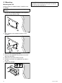
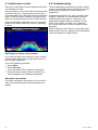
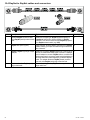
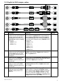
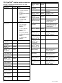
1
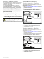
CP100 / CP200
Installation instructions
English
Date: 07-2014
Document number: 87216-1-EN
© 2014 Raymarine UK Limited
Trademark and patents notice
Raymarine, Tacktick, Clear Pulse, Truzoom, HSB, SeaTalk, SeaTalkhs, SeaTalkng, Micronet, Raytech,
Gear Up, Marine Shield, Seahawk, Autohelm, Automagic, and Visionality are registered or claimed
trademarks of Raymarine Belgium.
FLIR, DownVision, SideVision, Dragonfly, Instalert, Infrared Everywhere, and The World’s Sixth
Sense are registered or claimed trademarks of FLIR Systems, Inc.
All other trademarks, trade names, or company names referenced herein are used for identification only
and are the property of their respective owners.
This product is protected by patents, design patents, patents pending, or design patents pending.
Patents pending
Important: This product has patents pending.
Fair Use Statement
You may print no more than three copies of this manual for your own use. You may not make any further
copies or distribute or use the manual in any other way including without limitation exploiting the manual
commercially or giving or selling copies to third parties.
Software updates
Check the website www.raymarine.com for the latest software releases for your product.
Product handbooks
The latest versions of all English and translated handbooks are available to download in PDF format from the website
www.raymarine.com.
Please check the website to ensure you have the latest handbooks.
Copyright ©2014 Raymarine UK Ltd. All rights reserved.
ENGLISH
Document number: 87216-1
Date: 07-2014
Contents
Chapter 1 Important information........................ 7
6.6 Resetting the sonar module .................................. 43
Certified Installation ................................................... 7
Water ingress ............................................................ 8
Chapter 7 Maintenance ....................................... 45
Disclaimer ................................................................. 8
EMC installation guidelines ........................................ 8
Suppression ferrites ................................................... 8
Connections to other equipment ................................. 8
Declaration of conformity............................................ 8
Product disposal ........................................................ 8
Warranty registration.................................................. 8
IMO and SOLAS........................................................ 9
Technical accuracy .................................................... 9
Chapter 2 Document and product
information........................................................... 11
7.1 Routine checks .................................................... 46
7.2 Unit cleaning instructions ...................................... 46
7.3 Transducer care and cleaning ............................... 47
Chapter 8 Technical support .............................. 49
8.1 Raymarine customer support ................................ 50
8.2 Viewing product information .................................. 50
Chapter 9 Technical specification...................... 51
9.1 Technical specification.......................................... 52
Chapter 10 Spares and accessories .................. 53
10.1 Spares and accessories...................................... 54
2.1 Document information .......................................... 12
10.2 Network hardware .............................................. 54
2.2 Parts supplied...................................................... 13
2.3 Product overview ................................................. 14
10.3 Network cable connector types............................ 55
2.4 CHIRP Sonar overview......................................... 15
10.4 RayNet to RayNet cables and connectors ........... 56
10.5 RayNet to RJ45 adapter cables........................... 57
2.5 CHIRP DownVisionTM overview............................. 15
10.6 SeaTalkng cables and accessories ....................... 58
2.6 CHIRP SideVision™ overview ............................. 16
2.7 Interpreting SideVision™ images ......................... 17
2.8 CHIRP DownVision™ and CHIRP SideVision™
combined .................................................................. 18
Chapter 3 Planning the installation ................... 19
3.1 Installation checklist ............................................. 20
3.2 Required additional components ........................... 20
3.3 Compatible multifunction displays ......................... 21
3.4 Software updates ................................................. 21
3.5 Compatible transducers........................................ 22
3.6 Tools required ...................................................... 22
3.7 Typical systems ................................................... 23
3.8 Warnings and cautions ......................................... 24
3.9 General location requirements .............................. 24
3.10 Product dimensions............................................ 25
Chapter 4 Cables and connections.................... 27
4.1 General cabling guidance ..................................... 28
4.2 Connections overview .......................................... 29
4.3 Power connection ................................................ 29
4.4 Transducer connections ....................................... 31
4.5 Network connection.............................................. 32
Chapter 5 Mounting............................................. 35
5.1 Mounting ............................................................. 36
Chapter 6 System checks and
troubleshooting ................................................... 37
6.1 Initial power on test .............................................. 38
6.2 Troubleshooting ................................................... 38
6.3 Sonar troubleshooting .......................................... 39
6.4 Sonar crosstalk interference ................................. 40
6.5 LED indications.................................................... 42
5
6
CP100 / CP200
Chapter 1: Important information
Warning: Ensure all equipment has
isolated power supply
Certified Installation
This product features an isolated power
supply. To prevent potential damage to
equipment, Raymarine recommends that
any external equipment connected to this
product also features an isolated power
supply.
Raymarine recommends certified installation by a
Raymarine approved installer. A certified installation
qualifies for enhanced product warranty benefits.
Contact your Raymarine dealer for further details,
and refer to the separate warranty document packed
with your product.
Warning: Product installation and
operation
This product must be installed and
operated in accordance with the
instructions provided. Failure to do so
could result in personal injury, damage
to your vessel and/or poor product
performance.
Warning: High voltage
This product contains high voltage.
Adjustments require specialized service
procedures and tools only available to
qualified service technicians. There are
no user serviceable parts or adjustments.
The operator should never remove the
cover or attempt to service the product.
Warning: Transducer cables
This product is NOT approved for use in
hazardous/flammable atmospheres. Do
NOT install in a hazardous/flammable
atmosphere (such as in an engine room
or near fuel tanks).
Do not remove the transducer cable whilst
the product is powered on, doing so can
cause sparks. If the transducer cable is
accidently removed whilst the product is
powered on, switch the product's power
off, replace the cable and then switch the
power back on.
Warning: Product grounding
Warning: Sonar operation
Before applying power to this product,
ensure it has been correctly grounded, in
accordance with the instructions in this
guide.
• NEVER operate the sonar with the
vessel out of the water.
Warning: Positive ground systems
• SWITCH OFF the sonar if divers are
likely to be within 7.6 m (25 ft) of the
transducer.
Warning: Potential ignition source
Do not connect this unit to a system which
has positive grounding.
• NEVER touch the transducer face when
the sonar is powered on.
Warning: Power supply voltage
Caution: Do not cut transducer
cables
Connecting this product to a voltage
supply greater than the specified
maximum rating may cause permanent
damage to the unit. Refer to the Technical
specification section for voltage rating.
• Cutting the transducer cable severely
reduces sonar performance. If the
cable is cut, it must be replaced, it
cannot be repaired.
Warning: Switch off power supply
Ensure the vessel’s power supply is
switched OFF before starting to install this
product. Do NOT connect or disconnect
equipment with the power switched on,
unless instructed in this document.
Caution: Power supply protection
• Cutting the transducer cable will
void the warranty and invalidate the
European CE mark.
Caution: Service and maintenance
This product contains no user serviceable
components. Please refer all maintenance
and repair to authorized Raymarine
dealers. Unauthorized repair may affect
your warranty.
When installing this product ensure the
power source is adequately protected
by means of a suitably-rated fuse or
automatic circuit breaker.
Important information
7
Water ingress
Water ingress disclaimer
Although the waterproof rating capacity of this
product meets the stated IPX standard (refer to the
product’s Technical Specification), water intrusion
and subsequent equipment failure may occur if the
product is subjected to commercial high-pressure
washing. Raymarine will not warrant products
subjected to high-pressure washing.
Disclaimer
Raymarine does not warrant that this product is
error-free or that it is compatible with products
manufactured by any person or entity other than
Raymarine.
Note: Where constraints on the installation
prevent any of the above recommendations,
always ensure the maximum possible separation
between different items of electrical equipment, to
provide the best conditions for EMC performance
throughout the installation
Suppression ferrites
Raymarine cables may be fitted with suppression
ferrites. These are important for correct EMC
performance. If a ferrite has to be removed for any
purpose (e.g. installation or maintenance), it must be
replaced in the original position before the product
is used.
Use only ferrites of the correct type, supplied by
Raymarine authorized dealers.
Raymarine is not responsible for damages or injuries
caused by your use or inability to use the product,
by the interaction of the product with products
manufactured by others, or by errors in information
utilized by the product supplied by third parties.
Where an installation requires multiple ferrites to be
added to a cable, additional cable clips should be
used to prevent stress on the connectors due to the
extra weight of the cable.
EMC installation guidelines
Connections to other equipment
Raymarine equipment and accessories conform to
the appropriate Electromagnetic Compatibility (EMC)
regulations, to minimize electromagnetic interference
between equipment and minimize the effect such
interference could have on the performance of your
system
Requirement for ferrites on non-Raymarine cables
If your Raymarine equipment is to be connected
to other equipment using a cable not supplied by
Raymarine, a suppression ferrite MUST always be
attached to the cable near the Raymarine unit.
Correct installation is required to ensure that EMC
performance is not compromised.
Declaration of conformity
Note: In areas of extreme EMC interference,
some slight interference may be noticed on the
product. Where this occurs the product and the
source of the interference should be separated by
a greater distance.
For optimum EMC performance we recommend
that wherever possible:
• Raymarine equipment and cables connected to
it are:
– At least 1 m (3 ft) from any equipment
transmitting or cables carrying radio signals e.g.
VHF radios, cables and antennas. In the case
of SSB radios, the distance should be increased
to 7 ft (2 m).
– More than 2 m (7 ft) from the path of a radar
beam. A radar beam can normally be assumed
to spread 20 degrees above and below the
radiating element.
• The product is supplied from a separate battery
from that used for engine start. This is important to
prevent erratic behavior and data loss which can
occur if the engine start does not have a separate
battery.
• Raymarine specified cables are used.
• Cables are not cut or extended, unless doing so is
detailed in the installation manual.
8
Raymarine UK Ltd. declares that this product is
compliant with the essential requirements of EMC
directive 2004/108/EC.
The original Declaration of Conformity certificate
may be viewed on the relevant product page at
www.raymarine.com.
Product disposal
Dispose of this product in accordance with the
WEEE Directive.
The Waste Electrical and Electronic Equipment
(WEEE) Directive requires the recycling of waste
electrical and electronic equipment. Whilst the
WEEE Directive does not apply to some Raymarine
products, we support its policy and ask you to be
aware of how to dispose of this product.
Warranty registration
To register your Raymarine product ownership,
please visit www.raymarine.com and register online.
It is important that you register your product to
receive full warranty benefits. Your unit package
includes a bar code label indicating the serial number
CP100 / CP200
of the unit. You will need this serial number when
registering your product online. You should retain
the label for future reference.
IMO and SOLAS
The equipment described within this document
is intended for use on leisure marine boats and
workboats NOT covered by International Maritime
Organization (IMO) and Safety of Life at Sea
(SOLAS) Carriage Regulations.
Technical accuracy
To the best of our knowledge, the information in this
document was correct at the time it was produced.
However, Raymarine cannot accept liability for any
inaccuracies or omissions it may contain. In addition,
our policy of continuous product improvement may
change specifications without notice. As a result,
Raymarine cannot accept liability for any differences
between the product and this document. Please
check the Raymarine website (www.raymarine.com)
to ensure you have the most up-to-date version(s) of
the documentation for your product.
Important information
9
10
CP100 / CP200
Chapter 2: Document and product information
Chapter contents
•
•
•
•
•
•
•
•
2.1 Document information on page 12
2.2 Parts supplied on page 13
2.3 Product overview on page 14
2.4 CHIRP Sonar overview on page 15
2.5 CHIRP DownVisionTM overview on page 15
2.6 CHIRP SideVision™ overview on page 16
2.7 Interpreting SideVision™ images on page 17
2.8 CHIRP DownVision™ and CHIRP SideVision™ combined on page 18
Document and product information
11
2.1 Document information
Document conventions
This document contains important information
related to the installation of your Raymarine product.
The following conventions are used throughout this
document when referring to:
The document includes information to help you:
Type
• plan your installation and ensure you have all the
necessary equipment;
Procedures for
Select
performing specific Transducer
tasks using a
Set-Up.
multifunction
display.
• install and connect your product as part of a wider
system of connected marine electronics;
Example
• troubleshoot problems and obtain technical
support if required.
This and other Raymarine product documents
are available to download in PDF format from
www.raymarine.com.
Applicable products
This document is applicable to the following products:
Part number Name
Description
E70204
CP100
2–channel
CHIRP /
DownVision
sonar module
E70205
CP100 and
CPT-100
2–channel
CHIRP /
DownVision
sonar
module and
DownVision
transom
transducer.
E70256
E70257
12
CP200
CP200 and
CPT-200
2–channel
CHIRP /
SideVision
sonar module
2–channel
CHIRP /
SideVision
sonar
module and
SideVision
transom
transducer.
Procedures for
navigating menu
hierarchies on
a multifunction
display.
Internal sonar
module is
turned off from
the Fishfinder
application menu:
Menu > Set-up >
Sounder Set-up >
Internal Sounder.
Convention
The term “Select”
is used to refer
to the action
of selecting a
menu option on
a multifunction
display, using the
touchscreen or
physical controls,
depending on
display variant.
Menu hierarchies
are used in this
document to
provide a quick
summary on
how to access
a particular
function on the
multifunction
display.
Document illustrations
Your product may differ slightly from that shown
in the illustrations in this document, depending on
product variant and date of manufacture.
All images are provided for illustration purposes only.
Product documentation
The following documentation is applicable to your
product:
Description
Part number
CP100 / CP200 Installation instructions
Installation of a CP100 or CP200 unit and
connection to a wider system of marine
electronics.
87216 /
88030
CP100 / CP200 Mounting template
Mounting diagram for surface mounting a
CP100 or CP200 unit.
87193
CPT–60 / CPT–100 DownVision transom
transducer Installation instructions
Installation of a DownVision transom-mount
transducer.
87197 /
88024
CPT–200 SideVision transom transducer
Installation instructions
Installation of a SideVision transom-mount
transducer.
87223 /
88037
CPT–110 / CPT–120 Through-hull
transducer Installation instructions
Installation of a DownVision through-hull
transducer.
87201 /
88025
CP100 / CP200
Description
Part number
a Series, c Series, e Series Installation and 81337
operation instructions
Details the operation of the fishfinder
application (including DownVision and
SideVision operation) for a Series, c Series,
e Series multifunction displays.
gS Series Installation and operation
instructions
Details the operation of the fishfinder
application (including DownVision and
SideVision operation) for gS Series
multifunction displays.
2.2 Parts supplied
Parts supplied — CP100 / CP200
81344
2
1
Operation instructions
3
For detailed operation instructions for your product,
refer to the documentation that accompanies your
display.
Transducer installation instructions
This document includes installation instructions for
the sonar module only. For installation instructions
for a connected transducer, please refer to the
documentation that accompanies the transducer.
Document and product information
4
D12934-1
Item
Description
Quantity
1
Sonar module.
1
2
Documentation pack.
1
3
Mounting screws.
4
4
Power cable 1 m
(3.28 ft).
1
13
2.3 Product overview
• Dual-beam sonar (port and starboard fan beam).
• Typical range performance of 300 ft.
CP100 product overview
The CP100 is a CHIRP sonar module with
DownVision capabilities. In conjunction with a
compatible multifunction display, the CP100 provides
a detailed view of the water’s bottom structure,
enabling you to identify fish and other objects in the
water underneath your vessel.
• Water temperature sensing.
• Support for transom-mount SideVision
transducers.
• Low power consumption.
• 12 V or 24 V operation.
• Waterproof to IPX 6 and IPX 7.
• Robust and waterproof high-speed network
connection.
D12932-1
The CP100 has the following features:
• Dual-beam sonar (conical beam and fan beam).
• Typical depth performance of 600 ft.
• Water temperature sensing.
• Support for transom or through-hull DownVision
transducers.
• Low power consumption.
• 12 V or 24 V operation.
• Waterproof to IPX 6 and IPX 7.
• Robust and waterproof high-speed network
connection.
CP200 product overview
The CP200 is a CHIRP sonar module with
SideVision capabilities. In conjunction with a
compatible multifunction display, the CP200 provides
a detailed view of the water’s bottom structure on
each side of your vessel, enabling you to identify
bottom features, as well as fish and other objects
in the water.
D12932-1
The CP200 has the following features:
14
CP100 / CP200
2.4 CHIRP Sonar overview
2.5 CHIRP DownVisionTM overview
CHIRP sonar produces a conical shaped beam, the
coverage of the conical beam is the water column
directly beneath the vessel
DownVisionTM produces a wide–angle side-to-side
beam and a thin fore-to-aft beam. The coverage of
the DownVisionTM beam is a water column directly
beneath and to the sides of the vessel.
Conical beam
DownVisionTM beam
D12777-2
D12784-2
Sonar is effective at a range of speeds. In deeper
waters the CHIRP bandwidth is automatically
optimized to improve bottom lock and the detection
of moving objects (e.g. fish) in the wider water
column.
CHIRP sonar screen example
DownVisionTM is effective at lower vessel speeds. In
deeper waters the CHIRP bandwidth is automatically
optimized to improve bottom lock and the detection of
moving objects (e.g. fish) in the wider water column.
The wide, thin beam produces clear target returns.
The use of CHIRP processing and a higher operating
frequency provide a more detailed image, making
it easier to identify bottom structures around which
fish may reside.
CHIRP DownVisionTM screen example
Document and product information
15
2.6 CHIRP SideVision™ overview
SideVision™ interprets signals from a pair of
side-looking transducers and builds up a detailed
underwater view as your vessel moves forward.
The transducers send pulses of sound waves into
the water on each side of your vessel, and record
the sound waves that reflect off the bottom, and off
objects on the bottom or suspended in the water
column. The received echoes are affected by the
bottom material (for example mud, gravel or rock),
and by any other objects in their path (for example
cables on the sea floor, bridge piers, wrecks, shoals
or fish).
Note: The “Depth” figure shown in the illustration
above assumes that you have a device in your
system that provides depth data. Please be aware
that not all transducers and / or sonar modules
support depth sensing. For more information, refer
to the latest specifications and documentation
available for your particular products on the
Raymarine website (www.raymarine.com).
SideVision™ produces two wide–angle side-to-side
beams, each with a thin fore-to-aft beam. The
coverage of the SideVision™ beams is a swath on
each side of the vessel.
SideVision beams
D#####-1
SideVision™ is effective at lower vessel speeds.
The wide, thin beams produce clear target returns.
As your vessel moves forward, subsequent returns
build up to provide an image of the sea floor on each
side of your vessel.
The use of CHIRP processing and a high operating
frequency provide a detailed image, making it easier
to identify bottom structures around which fish may
reside. The narrow angle the beams make with the
bottom at longer ranges can reveal the shadows of
structures that protrude from the bottom.
CHIRP SideVision™ screen example
16
CP100 / CP200
2.7 Interpreting SideVision™ images
The following illustration shows how SideVision™ images on your multifunction display are related to the
water column and sea floor to the sides of your vessel.
Interpreting SideVision images
Distance from
vessel, e.g.
150 ft ( not
depth)
Depth is only displayed if there is a
source of depth data on the network
e c tio n
ir
Ve s s e l d
P O RT
AR D
S TAR BO
Wa
te
De pt
Depth
62.9 ft
62.9
Dis
ta
r
Ba
it b
a ll V
eg
e ta
tio
S TARBOARD
BOARD
nce
=1
Structure
50
ft
Ve ge ta tion
n
S tr
uc
tu r
e
Ve s s e l S TARBOARD
dire ction
direction
Ima ge s croll dire ction
POR T
s c ro ll
Im a g e
io n
d ire c t
Bait ball
Wa te r
D13166-1
SideVision™ images are constructed line-by-line,
similar to the way a television picture is composed
of many horizontal lines. Each successive ping
from the SideVision™ transducer adds a new line
of image data to the top of your display. Each new
line shows sonar returns from both the port and
starboard sides of your vessel.
As new lines are added with each successive
ping, older data gradually scrolls down the display,
building up a detailed image of the water column and
sea floor to the sides of your vessel. If your vessel
maintains the same bearing and speed for a period
of time, you can interpret the image as a plan of the
sea floor along your vessel’s course.
The illustration also identifies examples of features
that may be visible in SideVision™ images:
• Water: close to your vessel, the SideVision™
sonar beams may not interact with any solid
objects in the water column until they hit the sea
floor. The water column close to your vessel is
displayed as a dark band in the image. The abrupt
change to a lighter section in the image indicates
where the sea floor is first detected with each ping.
• Bait ball: objects in the water column close to your
vessel may be detected before the SideVision™
beams hit the sea floor. In this example, a bait ball
Document and product information
is shown within the water column, at a distance of
approximately 30 feet from the vessel.
• Vegetation: objects in contact with the sea floor
that are close to your vessel may be clearly visible
in the image at the point where the SideVision™
beams hit the sea floor. In this example, the
shapes in the image indicate vegetation attached
to the sea floor.
• Structure: the lighter regions of the SideVision™
image represent the sea floor. It may be possible
to detect differences in the bottom material (for
example, where an area of mud meets an area
of gravel) as well as solid structures such as
pipelines and piers. Larger solid structures, and
sea floor relief, may reveal an area of shadow
directed away from your vessel.
Note: Unlike DownVision™, SideVision™ does
not provide direct depth readings. The scale
shown across the top of the image indicates the
distance of features from your vessel.
17
2.8 CHIRP DownVision™ and CHIRP
SideVision™ combined
By installing and operating DownVision™ and
SideVision™ sonar systems simultaneously, you
can achieve a full 180 degree view of the water
column directly beneath and to the sides of your
vessel.
DownVision and SideVision combined beams
Note: Using DownVision™ and SideVision™
together requires two separate sounders in your
system:
1. A DownVision™ sounder: either an
internal sounder in a DownVision™
variant multifunction display, or an external
DownVision™ sonar module (such as a
CP100).
2. An external SideVision™ sonar module (such
as a CP200).
18
CP100 / CP200
Chapter 3: Planning the installation
Chapter contents
•
•
•
•
•
•
•
•
•
•
3.1 Installation checklist on page 20
3.2 Required additional components on page 20
3.3 Compatible multifunction displays on page 21
3.4 Software updates on page 21
3.5 Compatible transducers on page 22
3.6 Tools required on page 22
3.7 Typical systems on page 23
3.8 Warnings and cautions on page 24
3.9 General location requirements on page 24
3.10 Product dimensions on page 25
Planning the installation
19
3.1 Installation checklist
3.2 Required additional components
Installation includes the following activities:
This product forms part of a system of electronics
and requires the following additional components for
full operation.
Installation Task
1
Plan your system.
2
Obtain all required equipment and tools.
3
Site all equipment.
4
Route all cables.
5
Drill cable and mounting holes.
6
Make all connections into equipment.
7
Secure all equipment in place.
8
Power on and test the system.
Schematic diagram
• Compatible transducer; transom or through-hull
mount. Refer to 3.5 Compatible transducers
for a list of compatible products.
• Compatible Raymarine multifunction display.
Refer to 3.3 Compatible multifunction displays for
a list of compatible products.
• Data cables. Refer to Chapter 4 Cables and
connections for suitable cables. Some installations
may also require extensions to data, power or
transducer cables. Refer to the Chapter 4 Cables
and connections and Chapter 10 Spares and
accessories sections for more information.
A schematic diagram is an essential part of planning
any installation. It is also useful for any future
additions or maintenance of the system. The
diagram should include:
• Location of all components.
• Connectors, cable types, routes and lengths.
20
CP100 / CP200
3.3 Compatible multifunction displays
3.4 Software updates
This product is compatible with the following
LightHouse powered Raymarine multifunction
displays.
The software running on the product can be updated.
• a Series, c Series, e Series.
• gS Series.
Multifunction display software requirements
The operation of this product requires that your
Raymarine LightHouse powered MFD is running
LightHouse software version 11 or later.
Note: The latest MFD software can be obtained
by visiting www.raymarine.com/software.
• Raymarine periodically releases software updates
to improve product performance and add new
features.
• You can update the software for your product using
a connected and compatible multifunction display.
• Refer to www.raymarine.com/software/ for the
latest software updates and the software update
procedure for your product.
• If in doubt as to the correct procedure for updating
your product software, refer to your dealer or
Raymarine technical support.
Caution: Downloading software
updates
The software update process is carried
out at your own risk. Before initiating the
update process ensure you have backed
up any important files.
Ensure that the unit has a reliable power
supply and that the update process is not
interrupted.
Damage caused by incomplete updates
are not covered by Raymarine warranty.
By downloading the software update
package, you agree to these terms.
Planning the installation
21
3.5 Compatible transducers
3.6 Tools required
CP100 compatible transducers
Product installation requires the following tools:
This product is compatible with the following
Raymarine transducers.
Part
number
Description
Mounting ConType
struction
A80270
CPT-100
DownVision
transducer
Transom
CPT-110
DownVision
transducer
Throughhull
CPT-120
DownVision
transducer
Throughhull
A80277
A80271
Item
Description
Quantity
Power drill
1
Pozidrive screwdriver
1
Plastic
Plastic
Drill bit of appropriate size* 1
Bronze
Adhesive tape
1
CP200 compatible transducers
This product is compatible with the following
Raymarine transducers.
Part
number
Description
Mounting ConType
struction
A80281
CPT-200
SideVision
transducer
Transom
22
Note: * The appropriate drill bit size is dependent
on the thickness and material of the mounting
surface.
Marinegrade
stainless
steel /
plastic
CP100 / CP200
3.7 Typical systems
Example: expanded sonar system featuring
autopilot system and multifunction display
Note: The following illustrations show the various
products that can be connected in a typical system.
• Systems that include a CP200 sonar module
can use a SideVision transducer in place of the
illustrated DownVision transducer.
2
• For information on how to connect the products,
refer to the Chapter 4 Cables and connections
section.
2
3
RayNet
RayNet
1
• For information on available cables and
accessories, refer to the Chapter 10 Spares and
accessories section.
5
4
Example: basic sonar system featuring
multifunction display
6
7
9
SeaTalkng
8
10
0
2
1
SeaTalkng
3
D12938-1
4
D12937-1
Item
Description
1
Sonar module
2
RayNet cables
Item
Description
3
RayNet network switch
1
Multifunction display
4
Radar scanner
2
Sonar module
5
Multifunction display
3
RayNet cable
6
DownVision transducer
4
DownVision transducer
7
Evolution ACU
8
SeaTalkng spur cable
9
Evolution EV
10
Pilot head controller
Planning the installation
23
3.8 Warnings and cautions
Important: Before proceeding, ensure that you
have read and understood the warnings and
cautions provided in the Chapter 1 Important
information section of this document.
3.9 General location requirements
Important considerations when choosing a suitable
location for your product.
This product is suitable for mounting above or below
decks.
The product should be mounted where it will be:
• protected from physical damage and excessive
vibration.
• well ventilated and away from heat sources.
• away from any potential ignition source such as an
engine room, near fuel tanks or a gas locker.
When choosing a location for the product,
consider the following points to ensure reliable and
trouble-free operation:
• Access — there must be sufficient space to
enable cable connections to the product, avoiding
tight bends in the cable.
• Diagnostics — the product must be mounted in
a location where the diagnostics LED is easily
visible.
Note: Not all products include a diagnostics
LED. Refer to the Chapter 6 System checks
and troubleshooting for more information.
• Electrical interference — the product should be
mounted far enough away from any equipment
that may cause interference such as motors,
generators and radio transmitters / receivers.
• Magnetic compass — refer to the Compass
safe distance section in this document for advice
on maintaining a suitable distance between this
product and any compasses on your vessel.
• Power — to keep cable runs to a minimum, the
product must be located as close as possible to
the vessel’s dc power supply.
• Mounting surface — ensure the product is
adequately supported on a secure surface. Refer
to the weight information provided in the Technical
specification for this product and ensure that the
intended mounting surface is suitable for bearing
the product weight. Do NOT mount units or cut
holes in places which may damage the structure
of the vessel.
Compass safe distance
To prevent potential interference with the vessel's
magnetic compasses, ensure an adequate distance
is maintained from the product.
When choosing a suitable location for the product
you should aim to maintain the maximum possible
distance from any compasses. Typically this distance
should be at least 1 m (3 ft) in all directions. However
for some smaller vessels it may not be possible to
locate the product this far away from a compass. In
this situation, when choosing the installation location
for your product, ensure that the compass is not
affected by the product when it is in a powered state.
24
CP100 / CP200
3.10 Product dimensions
171 mm (6.7 in)
162 mm (6.4 in)
72 mm (2.8 in)
205 mm (8.1 in)
225 mm (8.9 in)
D12941-1
Planning the installation
25
26
CP100 / CP200
Chapter 4: Cables and connections
Chapter contents
•
•
•
•
•
4.1
4.2
4.3
4.4
4.5
General cabling guidance on page 28
Connections overview on page 29
Power connection on page 29
Transducer connections on page 31
Network connection on page 32
Cables and connections
27
4.1 General cabling guidance
Cable types and length
It is important to use cables of the appropriate type
and length
• Unless otherwise stated use only standard cables
of the correct type, supplied by Raymarine.
and other sensitive electronic instruments or
devices.
• Always use an isolating transformer with Weather
FAX audio cables.
• Always use an isolated power supply when using
a 3rd party audio amplifier.
• Always use an RS232/NMEA converter with
optical isolation on the signal lines.
• Ensure that any non-Raymarine cables are of the
correct quality and gauge. For example, longer
power cable runs may require larger wire gauges
to minimize voltage drop along the run.
• Always make sure that PC’s or other sensitive
electronic devices have a dedicated power circuit.
Routing cables
Cable shielding
Cables must be routed correctly, to maximize
performance and prolong cable life.
Ensure that all data cables are properly shielded
that the cable shielding is intact (e.g. hasn’t been
scraped off by being squeezed through a tight area).
• Do NOT bend cables excessively. Wherever
possible, ensure a minimum bend diameter of 200
mm (8 in) / minimum bend radius of 100 mm (4 in).
Cable ferrite installation
Your product may be supplied with cable ferrites. To
ensure EMC Compliance, any supplied ferrites must
be fitted to the cables according to the following
instructions.
200 mm (8 in)
100 mm (4 in)
1
2x
Ma x. 200 mm (7.87 in)
• Protect all cables from physical damage and
exposure to heat. Use trunking or conduit where
possible. Do NOT run cables through bilges or
doorways, or close to moving or hot objects.
4
• Secure cables in place using tie-wraps or lacing
twine. Coil any extra cable and tie it out of the way.
• Where a cable passes through an exposed
bulkhead or deckhead, use a suitable watertight
feed-through.
• Do NOT run cables near to engines or fluorescent
lights.
Always route data cables as far away as possible
from:
2x
7
2
5
3
6
• other equipment and cables,
• high current carrying ac and dc power lines,
• antennae.
Caution: Pulling cables
Do NOT use cords or ropes, attached
to cable connectors, to pull cables
through restricted apertures (e.g. as in
bulkheads), as this could cause damage
to cables.
Strain relief
Ensure adequate strain relief is provided. Protect
connectors from strain and ensure they will not pull
out under extreme sea conditions.
Circuit isolation
Appropriate circuit isolation is required for
installations using both AC and DC current:
D13014-1
1. RayNet cable.
2. Fit 2 ferrites to the RayNet cable. There should
be no gap between the 2 ferrites.
3. Secure the ferrites in place using the supplied
cable ties.
4. Power cable.
5. Fit 2 ferrites to the power cable. There should be
no gap between the 2 ferrites.
6. Secure the ferrites in place using the supplied
cable ties.
7. Ensure the distance between the end of the last
ferrite and the top of the connector is no more
than 200 mm (7.87 in).
Note: If the ferrites are supplied in different sizes,
ensure that you select the correct size for the
appropriate cable. This is confirmed by a tight fit.
• Always use isolating transformers or a separate
power-inverter to run PC’s, processors, displays
28
CP100 / CP200
4.3 Power connection
4.2 Connections overview
Use the following information to help you identify the
connections on your product.
Connector
Connector
panel label Connects to:
Suitable
cables
Network
RayNet
network or
device.
Refer to the
Chapter 10
Spares and
accessories
section.
12 V / 24 V
power supply.
Supplied with
your product.
Power
Transducer Compatible
transducer.
Supplied
with the
transducer.
Making connections
Follow the steps below to connect the cable(s) to
your product.
1. Ensure that the vessel's power supply is switched
off.
2. Ensure that the device being connected to the
unit has been installed in accordance with the
installation instructions supplied with that device.
3. Ensuring correct orientation, push the cable
connector fully onto the corresponding connector
on the unit.
4. Turn the locking collar clockwise to secure the
cable.
3
1
2
4
5
D12947-1
Note: For clarity, only the power-related cables
are shown in the illustration above.
Item
Description
Connects to:
1
Power cable.
Product’s power
connector.
2
Red cable (positive)
Power supply’s positive
terminal.
3
Connection to 12 V /
24 V power supply.
Power supply.
4
Shield (drain) wire
Must be connected to
RF ground point.
5
Black cable (negative)
Power supply’s negative
terminal.
Power cable extension
The product is supplied with a power cable, which
can be extended if required.
• The power cable for each unit in your system
should be run as a separate, single length of
2-wire cable from the unit to the vessel's battery or
distribution panel.
• Raymarine recommends a minimum wire gauge
of 18AWG (0.82 mm2) for any length of cable
extension.
• Regardless of the length of the cable extension,
any cable used should be capable of achieving a
minimum voltage at the unit of 10.8 V with a fully
flat battery at 11 V.
Power distribution
Raymarine recommends that all power connections
are made via a distribution panel.
• All equipment must be powered from a breaker or
switch, with appropriate circuit protection.
• Refer to the Breakers, fuses and circuit protection
section for specific fuse and thermal breaker
ratings for this product.
Breakers, fuses and circuit protection
The information below is provided as guidance
to help protect your product. The example
illustrations provided are for common vessel power
arrangements, if you are unsure how to provide the
correct level of protection then please consult a
Raymarine authorized dealer for support.
Cables and connections
29
Distribution panel connection
It is recommended that your product is wired through
your vessel’s distribution panel via a thermal breaker
or fuse.
1
2
1
2
3
4
5
3
6
D13019-1
1. Vessel power supply positive (+)
4
5
6
2. Vessel power supply negative (-)
7
1. Vessel power supply positive (+)
3. In-line fuse (If your products power cable does
not have a built in fuse then an in-line fuse
should be fitted.)
2. In-line fuse (your product may contain a fuse
already built in to the power cable.)
4. * Drain wire connected to vessel negative power
supply.
3. Product power cable
5. Product power cable
4. Vessel power supply negative (-)
6. Vessel battery
D13017-1
5. * Drain wire
Note: * Only applicable to products that include a
drain wire on the product’s power cable.
6. Vessel distribution panel
7. * Vessel RF ground point connection
Note: * Only applicable to products that include a
drain wire on the product’s power cable.
Thermal breaker rating
5 A (if only connecting one device)
Sharing a breaker
Where more than 1 piece of equipment shares a
breaker you must provide protection for the individual
circuits. E.g. by connecting an in-line fuse for each
power circuit.
-
+
Battery connection with RF ground
If your vessel does not have a distribution panel then
your product may be wired directly to the battery with
the drain wire connected to the vessel’s RF ground
point.
1
2
3
6
4
1
2
3
5
7
4
D13018-1
4
1. Vessel power supply positive (+)
2. Vessel power supply negative (-)
D11637-2
1
Positive (+) bar
3. In-line fuse (If your products power cable does
not have a built in fuse then an in-line fuse
should be fitted.)
2
Negative (-) bar
3
Circuit breaker
4. * Drain wire
4
Fuse
5. Product power cable
6. Vessel battery
7. * Vessel RF ground point connection
Note: * Only applicable to products that include a
drain wire on the product’s power cable.
Battery connection with no RF ground
If your vessel does not have a distribution panel
or an RF ground point then your product may be
wired directly to the battery with the drain wire also
connected to the battery’s negative terminal.
30
Where possible, connect individual items of
equipment to individual circuit breakers. Where this
is not possible, use individual in-line fuses to provide
the necessary protection.
Warning: Product grounding
Before applying power to this product,
ensure it has been correctly grounded, in
accordance with the instructions in this
guide.
CP100 / CP200
Grounding — Dedicated drain wire
4.4 Transducer connections
The power cable supplied with this product includes
a dedicated shield (drain) wire for connection to a
vessel's RF ground point.
Transducer connection — DownVision
It is important that an effective RF ground is
connected to the system. A single ground point
should be used for all equipment. The unit can be
grounded by connecting the shield (drain) wire of
the power cable to the vessel's RF ground point.
On vessels without an RF ground system the shield
(drain) wire should be connected directly to the
negative battery terminal.
The dc power system should be either:
The CP100 sonar module is designed for use with
DownVision transducers.
• Refer to CP100 compatible transducers for a list of
compatible transducers.
• Transducers must be installed in accordance with
the instructions provided with the transducer.
1
• Negative grounded, with the negative battery
terminal connected to the vessel's ground.
• Floating, with neither battery terminal connected
to the vessel's ground
2
Warning: Positive ground systems
Do not connect this unit to a system which
has positive grounding.
3
D12940-1
1. CP100 sonar module.
2. Transducer cable (supplied with transducer).
3. DownVision transducer.
Transducer connection — SideVision
The CP200 sonar module is designed for use with
SideVision transducers.
• Refer to CP200 compatible transducers for a list of
compatible transducers.
• Transducers must be installed in accordance with
the instructions provided with the transducer.
1
2
3
D#####-1
1. CP200 sonar module.
2. Transducer cable (supplied with transducer).
3. SideVision transducer.
Cables and connections
31
Warning: Transducer cables
4.5 Network connection
Do not remove the transducer cable whilst
the product is powered on, doing so can
cause sparks. If the transducer cable is
accidently removed whilst the product is
powered on, switch the product's power
off, replace the cable and then switch the
power back on.
The unit must be connected to a compatible
Raymarine multifunction display to enable echo
sounder data to be viewed.
Multifunction display connection
Unit connected to a multifunction display using a
RayNet cable.
Caution: Do not cut transducer
cables
1
2
• Cutting the transducer cable severely
reduces sonar performance. If the
cable is cut, it must be replaced, it
cannot be repaired.
3
• Cutting the transducer cable will
void the warranty and invalidate the
European CE mark.
Transducer cable extension
For some installations it may be necessary to extend
the transducer cable.
D12234-3
Note: The connection panel on your product may
look slightly different to that shown, depending
on variant. The network connection method
remains the same for all products featuring RayNet
connectors.
• Refer to Chapter 10 Spares and accessories for a
list of suitable transducer extension cables.
Item
Description
• Raymarine recommends a maximum of one cable
extension for any single transducer cable.
1
Sonar module.
2
Connector panel for compatible Raymarine
multifunction display.
3
RayNet cable.
• For best performance, keep all cable lengths to
a minimum.
Multifunction display configuration (extended
cables)
When the required length of a single network cable
run is greater than 20 m (65.6 ft), a RayNet (male)
to (male) adaptor cable should be used to connect
RayNet cables together .
1
2
3
3
4
D12942-1
Note: The connection panel on your product may
look slightly different to that shown, depending
on variant. The network connection method
remains the same for all products featuring RayNet
connectors.
32
Item
Description
1
Sonar module.
2
Connector panel for compatible Raymarine
multifunction display.
3
RayNet cables.
4
RayNet (Male) to (Male) adaptor cable.
CP100 / CP200
Multiple multifunction display configuration
A Raymarine network switch can be used to connect
the unit to more than 1 multifunction display.
Note: Ensure network cables and connections are
tight and secure using any cable ties provided with
your network hardware.
1
2
3
4
5
2
2
D12236-3
Note: The connection panel on your product may
look slightly different to that shown, depending
on variant. The network connection method
remains the same for all products featuring RayNet
connectors.
Item
Description
1
Sonar module.
2
RayNet cable.
3
RayNet network switch.
4
Connector panel for compatible Raymarine
multifunction display.
5
Connector panel for additional compatible
Raymarine multifunction display.
For details on available network hardware and
cables refer to Chapter 10 Spares and accessories.
Cables and connections
33
34
CP100 / CP200
Chapter 5: Mounting
Chapter contents
•
5.1 Mounting on page 36
Mounting
35
5.1 Mounting
Note: Drill bit, tap size and tightening torque is
dependent on the thickness and type of material
the unit is to be mounted on.
Mounting the unit
Having chosen a suitable location, install the unit
as follows:
Note: Raymarine recommends mounting the unit
vertically.
1. Secure the mounting template in the required
location using adhesive tape.
Ra
ym
ar in
e CS
22
digi
ta l
C S2
so
un
2 Te
de
rm
m pl
od
ule
m
ou
nt in
g te
m pl
at e
at e
UP
108.2 mm (4.26 in)
421
IM
PO
en RTAN
su re
276
printT: Th is
.8 mm
ed do cu
(10
tem me
.90
299
pla nt
in)
.4 mm
te
(11
ma may
.78
tch no t
in)
es print
th e
me tru e
asur to
em scale
en . Be
ts pr for
ov e mo
ide
d. difyin
g mo
un
tin
g su
rfa
188.0 mm (7.40 in)
Doc
Dat um ent
e: 07- num
201 ber
1
: 871
34.6 mm (1.36 in)
Pilo
t hol
(4 pos
e
itio center
ns)
ce ,
D12
197
-1
D12240-1
2. Drill 4 holes at the marked location on the
template.
Ra
ym
ar in
e CS
22
digi
ta l
C S2
so
un
2 Te
de
rm
m pl
od
ule
m
ou
nt in
g te
m pl
at e
at e
UP
108.2 mm (4.26 in)
421
IM
PO
en RTAN
su re
276
printT: Th is
.8 mm
ed do cu
(10
tem me
.90
299
pla nt
in)
.4 mm
te
(11
ma may
.78
tch no t
in)
es print
th e
me tru e
asur to
em scale
en . Be
ts pr for
ov e mo
ide
d. difyin
g mo
un
tin
g su
rfa
188.0 mm (7.40 in)
Doc
Dat um ent
e: 07- num
201 ber
1
: 871
34.6 mm (1.36 in)
Pilo
t hol
(4 pos
e
itio center
ns)
ce ,
D12
197
-1
D12241-1
3. Remove the mounting template.
4. Screw in the supplied fixing screws about half
way into the holes.
5. Place the unit onto the fixing screws.
6. Push the unit down to engage the key slots in
the unit.
7. Tighten the screws
1
2
3
D12242-1
36
CP100 / CP200
Chapter 6: System checks and troubleshooting
Chapter contents
•
•
•
•
•
•
6.1
6.2
6.3
6.4
6.5
6.6
Initial power on test on page 38
Troubleshooting on page 38
Sonar troubleshooting on page 39
Sonar crosstalk interference on page 40
LED indications on page 42
Resetting the sonar module on page 43
System checks and troubleshooting
37
6.1 Initial power on test
6.2 Troubleshooting
Once the unit has been correctly installed check that
it is operating correctly.
The troubleshooting information provides possible
causes and corrective action required for common
problems associated with marine electronics
installations.
After powering on, the unit will take approximately 50
seconds to start up. From powering on through to
normal operation, the LED status indicator should be
green. If the LED status indicator is not green then
refer to the troubleshooting section of this handbook.
Open the Fishfinder application on your connected
multifunction display and ensure that it is operating
correctly.
All Raymarine products are, prior to packing and
shipping, subjected to comprehensive test and
quality assurance programs. However, if you
experience problems with the operation of your
product this section will help you to diagnose
and correct problems in order to restore normal
operation.
If after referring to this section you are still having
problems with your unit, please contact Raymarine
Technical Support for further advice.
Switching the active sonar module
If you have multiple sonar modules on your network
you can select which sonar module will be active in
the Fishfinder application.
From the Fishfinder application:
1. Select Menu.
2. Select Sounder:
A list of available sonar modules is displayed.
3. Select the Sonar module from the list that you
want to display in the Fishfinder application.
Operation instructions
For detailed operation instructions for your product,
refer to the documentation that accompanies your
display.
38
CP100 / CP200
6.3 Sonar troubleshooting
Problems with the sonar and their possible causes and solutions are described here.
Problem
Possible causes
Possible solutions
Sonar data not available on
multifunction display.
Unit power supply fault.
Check the unit power supply and cables.
Other unit fault.
Refer to the instructions supplied with the unit.
SeaTalkhs / RayNet network
problem.
Check that the unit is correctly connected to a Raymarine
network switch. If a crossover coupler or other coupler
cable / adapter is used, check all connections (as
applicable).
Check the status of the Raymarine network switch (if
applicable).
Check that SeaTalkhs/ RayNet cables are free from
damage.
Problematic data readings.
Note: Not all transducers
and / or sonar modules
support the detection of depth,
range and temperature. For
more information, refer to
the latest specifications and
documentation available
for your particular products
on the Raymarine website
(www.raymarine.com).
System checks and troubleshooting
Software mismatch between
equipment may prevent
communication.
Contact Raymarine technical support.
Gain or Frequency settings may
be inappropriate for present
conditions.
Check the sonar presets, gain and frequency settings.
Unit power supply fault.
Check the voltage from the power supply, if this is too low
it can affect the transmitting power of the unit.
Unit cable fault.
Ensure that the power, transducer and all other cables to
the unit are properly connected and free from damage.
Transducer fault.
Check that the transducer is mounted correctly and is
clean.
If you have a transom mount transducer, check that the
transducer hasn't kicked-up due to hitting an object.
Other unit fault.
Refer to the instructions supplied with the unit.
Vessel stationary.
Fish arches are not displayed if the vessel is stationary;
fish will appear on the display as straight lines.
High vessel speed
Turbulence around the transducer may be confusing the
unit.
Scroll speed set to zero
Adjust the scroll speed.
39
6.4 Sonar crosstalk interference
There are 2 types of potential sonar crosstalk
interference in a Raymarine sonar system:
1. SideVision sonar crosstalk interference
2. Multiple sonar crosstalk interference
The types of crosstalk interference that you
may experience in your system depend on the
combination and type of sonar equipment installed,
and the way in which the equipment has been
installed.
SideVision sonar crosstalk Multiple sonar crosstalk
interference
interference
Due to the high sensitivity
of SideVision transducers,
you may experience some
minor crosstalk interference
between the left and right
receiving channels in areas
of strong target returns.
Examples of strong target
returns include solid objects
such as underwater bridge
structure. This interference
shows up in the Fishfinder
application as subtle
reflections from the right
sonar image displayed in
the left sonar image, or vice
versa.
When using multiple sonar
modules and transducers
operating in overlapping
frequency ranges, you may
experience some crosstalk
interference between the
ranges. This interference is
displayed in the Fishfinder
application as vertical “rain
drops” throughout the water
column. These vertical “rain
drops” indicate that 2 sonar
modules are operating in
close frequency proximity to
one another.
SideVision sonar crosstalk interference
Crosstalk interference is expected behavior in a high
sensitivity device such as a SideVision transducer,
and is not indicative of a fault with your transducer or
sonar module.
Reducing multiple sonar crosstalk
interference
Crosstalk interference in systems with multiple sonar
modules and transducers is the result of a number
of factors, including installation, operation, and
environment.
• Choose an equipment combination that
minimizes overlapping frequencies. Wherever
possible, choose to use sonar modules and
transducers that operate in different frequency
ranges (“Channels”), for example CP100 and
CP300 sonar modules and CPT-100 and B744V
transducers. This will help to ensure that each
component is operating in a distinct relative
frequency range – for example, a “high” frequency
range for the CP100 and a “low” frequency range
for the CP300.
• Only use the sonar channels that you really
need. Although it is possible to run multiple sonar
40
modules simultaneously in a Raymarine system, it
may not always be necessary to do so. If you are
in a scenario that requires only one sonar module
to be active at a time, disable any other sonar
modules by changing the Fishfinder application
pane to a single one which only displays the output
from one sonar module. Alternatively, disable the
ping for any unused sonar modules by selecting
MENU > Channel > Ping > OFF in the Fishfinder
application.
• Identify the sonar module and transducer that
is causing the interference. To do this, disable
the ping or remove the power for one of the sonar
modules in your system. If the interference in the
Fishfinder application disappears immediately,
you now know which device is causing the
interference. If the interference doesn’t disappear,
repeat the exercise again with the other sonar
module(s) in your system, one at a time. Once you
know which device is causing the interference,
proceed with the following methods to reduce the
interference from the relevant device.
• Adjust the Interference Rejection Filter. The
default setting for all Raymarine MFDs is “Auto”.
Changing this setting to “High” might help to
reduce interference (MENU > Setup > Sounder
Setup > Interference Rejection). Note that the
Interference Rejection Filter setting is not available
for all sonar modules.
• Decrease the power output of the interfering
transducer. Adjusting the “Power Mode” in
the Sensitivity Settings in the MFD’s Fishfinder
application can help to minimize the presence
of crosstalk interference (MENU > Sensitivity
Settings > Power Mode). Note that the Power
Mode setting is not available for all transducers.
• Ensure that you have a common RF ground
point for all electrical equipment on your
vessel. On vessels without an RF ground system,
ensure all product drain wires (where available)
are connected directly to the negative battery
terminal. Ineffective RF grounding can cause
electrical interference which may in turn result in
sonar crosstalk interference.
• Increase the physical distance between your
sonar modules. Electrical interference may be
occurring between a cable on one sonar module,
and a cable on a different sonar module. Ensure
that your sonar modules are physically located as
far away from each other as possible.
• Increase the physical distance between your
sonar transducers. Electrical and / or acoustic
interference may be occurring between the
different transducers in your system. Ensure that
your transducers are physically located as far
away from each other as possible.
Note: Given the effort and potential difficulties
involved in relocating sonar equipment, it should
only be considered as a last resort when you judge
the interference to be a significant problem which
cannot be resolved using the methods described
above.
CP100 / CP200
Note: Due to physical size and other constraints
that vary from vessel to vessel, it may not
be possible to completely eliminate crosstalk
interference from your system. However, this
will not impede your ability to benefit from the
full capabilities of your sonar system. Being able
to easily identify the way in which interference
is displayed in the Fishfinder application can
sometimes be the best and easiest route to dealing
with it.
System checks and troubleshooting
41
6.5 LED indications
The power LED for this product has a number of flashing (blinking) modes to provide status information for
diagnostics and troubleshooting.
LED color
LED code
Status
User action
Solid
Green
Power On
• None (normal power up takes <1 minute.)
Green 1
blink
Normal
operation
• None
Amber 1
blink
Transducer
disconnected
• Ensure transducer cable and connections are
secure and free from damage.
• Power cycle unit to recover transducer
information.
• If problem persists contact Raymarine technical
support.
Amber 2
blinks
No network
detected
• Ensure network is powered.
• Ensure network cable and connections are
secure and free from damage.
• If problem persists contact Raymarine technical
support.
Amber 5
blinks
Under voltage
(<10.2V)
• Ensure power cable and connections are secure
and free from damage.
• Ensure power supply cabling is consistent with
recommendations.
• If problem persists contact Raymarine technical
support.
Amber 6
blinks
Over voltage
(>34.2V)
• Ensure power supply levels are consistent with
recommendations.
• If problem persists contact Raymarine technical
support.
Red 1
blink
General failure
• If combined with voltage warning, check power
supply and cables.
• Power-cycle the unit.
• If problem persists contact Raymarine technical
support.
Red 3
blinks
Unit
overheating
• Ensure installation environment is within
recommendations.
• Unit will stop pinging and then start again once
normal operating temperature is achieved.
• If problem persists contact Raymarine technical
support.
Red 4
blinks
Problems
with internal
database
• Power-cycle the unit.
• If problem persists contact Raymarine technical
support.
Note: If any other LED sequence other than described above is seen and persists please contact
Raymarine technical support.
42
CP100 / CP200
6.6 Resetting the sonar module
You can use the reset function on a compatible
Raymarine multifunction display to restore the sonar
module to its factory default settings.
In
1.
2.
3.
4.
5.
the fishfinder application:
Select Menu.
Select Set-up.
Select Sounder Set-up.
Select Sonar Reset.
Select Yes to confirm or No to abort the operation,
as appropriate.
The unit will now be reset to factory default settings.
System checks and troubleshooting
43
44
CP100 / CP200
Chapter 7: Maintenance
Chapter contents
•
•
•
7.1 Routine checks on page 46
7.2 Unit cleaning instructions on page 46
7.3 Transducer care and cleaning on page 47
Maintenance
45
7.1 Routine checks
7.2 Unit cleaning instructions
The following periodic checks should be made:
The unit does not require regular cleaning. However,
if you find it necessary to clean the unit, please follow
the steps below:
1. Ensure power is switched off.
2. Wipe unit clean with a damp cloth.
3. If necessary, use a mild detergent solution to
remove grease marks.
• Examine cables for signs of damage, such as
chafing, cuts or nicks.
• Check that the cable connectors are firmly
attached and that their locking mechanisms are
properly engaged.
Note: Cable checks should be carried out with the
power supply switched off.
Warning: High voltage
This product contains high voltage.
Adjustments require specialized service
procedures and tools only available to
qualified service technicians. There are
no user serviceable parts or adjustments.
The operator should never remove the
cover or attempt to service the product.
46
CP100 / CP200
7.3 Transducer care and cleaning
Growth can collect on the bottom of the transducer,
this can reduce performance. To prevent the build-up
of sea growth, coat the transducer with a thin layer
of water-based antifouling paint, available from
your local marine dealer. Reapply paint every 6
months or at the beginning of each boating season.
Certain smart transducers have restrictions on where
antifouling paint is applied. Please consult your
dealer.
Note: Transducers with a temperature sensor may
not work properly if painted.
Note: Never use ketone-based paint. Ketones
can attack many plastics, possibly damaging the
sensor.
Note: Never use spray paint on your transducer.
Spraying incorporates tiny air bubbles, and a
marine transducer cannot transmit properly
through air.
Use a soft cloth and mild household detergent to
clean the transducer. If the fouling is severe, remove
the growth with a tough cleaning pad, such as a
green Scotch BriteTM pad for example. Be careful to
avoid scratching the face of the transducer.
Note: Harsh cleaning solvents such as acetone
WILL damage the transducer.
Maintenance
47
48
CP100 / CP200
Chapter 8: Technical support
Chapter contents
•
•
8.1 Raymarine customer support on page 50
8.2 Viewing product information on page 50
Technical support
49
8.1 Raymarine customer support
8.2 Viewing product information
Raymarine provides a comprehensive customer
support service. You can contact customer support
through the Raymarine website, telephone and
e-mail. If you are unable to resolve a problem, please
use any of these facilities to obtain additional help.
You can view information about your unit from the
Diagnostics menu on a compatible multifunction
display. This option displays information such as
product serial number and software version.
Web support
Please visit the customer support area of our website
at:
www.raymarine.com
This contains Frequently Asked Questions, servicing
information, e-mail access to the Raymarine
Technical Support Department and details of
worldwide Raymarine agents.
With the Homescreen displayed:
1. Select Set-up.
2. Select Maintenance.
3. Select Diagnostics.
4. Select the Select Device option.
A list of connected devices is displayed.
5. Select the product for which you want to view
information. Alternatively, select Show All Data
to display information for all connected products.
Telephone and e-mail support
In the USA:
• Tel: +1 603 324 7900
• Toll Free: +1 800 539 5539
• E-mail: [email protected]
In the UK, Europe, and the Middle East:
• Tel: +44 (0)13 2924 6777
• E-mail: [email protected]
In Southeast Asia and Australia:
• Tel: +61 (0)29479 4800
• E-mail: [email protected]
Product information
If you need to request service, please have the
following information to hand:
• Product name.
• Product identity.
• Serial number.
• Software application version.
• System diagrams.
You can obtain this product information using the
menus within your product.
50
CP100 / CP200
Chapter 9: Technical specification
Chapter contents
•
9.1 Technical specification on page 52
Technical specification
51
9.1 Technical specification
Conformance
Physical specification
Dimensions
Conformance specification
• Width: 225 mm (8.9 in).
• Height: 162 mm (6.4 in).
• Height (including
connectors): 171 mm
(6.7 in).
• EN 60945:2002
• EMC Directive
2004/108/EC
• Australia and New
Zealand: C-Tick,
Compliance Level 2
• Depth: 72 mm (2.8 in).
Weight
0.6 kg (1.32 lbs)
Power specification
Nominal supply voltage
12 V / 24 V dc
Operating voltage range
10.8 V to 31.2 V dc
Power consumption
5.6 W (maximum)
Current
1 A peak
Fuse / breakers
5A
Sonar / DownVision specification
Channels
2 x CHIRP (1 x sonar and 1 x DownVision)
Beam
coverage
• Sonar — conical beam.
Depth
• DownVision — Wide (port / starboard)
and thin (fore / aft) fan beam.
Typical depth performance of 183 m (600
ft). Applies to both Sonar and DownVision
channels.
SideVision specification
Channels
2 x CHIRP
Beam
coverage
Port- and starboard-facing fan beams —
wide (port / starboard) and thin (fore / aft) .
Range
Up to 183 m (600 ft).
Note: Range performance is
dependent on many factors, including
water quality, transducer installation, and
reflectivity of targets and structure.
Environmental specification
Operating temperature
0°C to +55°C (+32°F to
+131°F)
Storage temperature
–30°C to +70°C (-22°F to
+158°F)
Relative humidity
95%
Waterproof rating
IPX6 and IPX7
52
CP100 / CP200
Chapter 10: Spares and accessories
Chapter contents
•
•
•
•
•
•
10.1
10.2
10.3
10.4
10.5
10.6
Spares and accessories on page 54
Network hardware on page 54
Network cable connector types on page 55
RayNet to RayNet cables and connectors on page 56
RayNet to RJ45 adapter cables on page 57
SeaTalkng cables and accessories on page 58
Spares and accessories
53
10.1 Spares and accessories
10.2 Network hardware
CP100 spares and accessories
The following accessories and spare parts are
available for the CP100:
Spares
Item
Part number
1 m (3.28 ft) power cable
A06049
Item
Part number
4 m (13.12 ft) transducer
extension cable for CPT-100
transom transducer
A80273
CPT-100 Transom
DownVision transducer
A80270
CPT-110 Through-hull
DownVision transducer
(plastic)
A80277
CPT-120 Through-hull
DownVision transducer
(bronze)
A80271
Notes
HS5 RayNet
network switch
A80007 5–port switch for network
connection of multiple
devices featuring RayNet
connectors. Equipment with
RJ45 SeaTalkhs connectors
can also be connected using
suitable adapter cables.
RJ45 SeaTalkhs
network switch
E55058 8–port switch for network
connection of multiple
SeaTalkhs devices featuring
RJ45 connectors.
RJ45 SeaTalkhs
crossover coupler
E55060 • Enables direct connection
of RJ45 SeaTalkhs devices
to smaller systems where
a switch is not required.
Accessories
Item
Part
number
• Enables the connection of
RJ45 SeaTalkhs devices
to a HS5 RayNet network
switch (in conjunction with
suitable adapter cables).
Transom transducer shield for A80207
vessels with a trolling motor
• Enables 2 RJ45 SeaTalkhs
cables to be connected
together to extend the
length of the cabling.
CP200 spares and accessories
The following accessories and spare parts are
available for the CP200:
Recommended for internal
installations.
Spares
Item
Part number
1 m (3.28 ft) power cable
A06049
Important: Do NOT use
crossover devices for POE
(Power Over Ethernet)
connections.
Accessories
Item
Part number
4 m (13.12 ft) transducer
extension cable for CPT-200
transom SideVision
transducer
A80305
CPT-200 Transom
SideVision transducer
A80281
Ethernet RJ45
coupler
R32142 • Enables direct connection
of RJ45 SeaTalkhs devices
to smaller systems where
a switch is not required.
• Enables the connection of
RJ45 SeaTalkhs devices
to a HS5 RayNet network
switch (in conjunction with
suitable adapter cables).
• Enables 2 RJ45 SeaTalkhs
cables to be connected
together to extend the
length of the cabling.
Recommended for external
installations.
54
CP100 / CP200
10.3 Network cable connector types
There are 2 types of network cable connector —
RayNet, and RJ45 SeaTalkhs.
RJ45 SeaTalkhs connector.
RayNet connector.
Spares and accessories
55
10.4 RayNet to RayNet cables and connectors
1
400 mm (1.3 ft)
A80161
2 m (6.56 ft)
5 m (16.4 ft)
20 m (65.6 ft)
A62361 A80005 A62362 A80006
2
3
R70014
4
10 m (32.8 ft)
A80262
100 mm (3.9 in)
A80162
D13160-1
Description
Typical use
Quantity
1
Standard RayNet connection cable
Suitable for connecting all RayNet equipment directly to
with a RayNet (female) socket on both LightHouse multifunction displays featuring a RayNet
ends.
connector. Can also be used to connect RayNet equipment
via a RayNet network switch (e.g. HS5).
1
2
RayNet cable puller (5 pack).
These “handles” securely attach to the twist-lock on RayNet
cables, enabling you to pull the cables through conduits and
other obstacles.
5
3
RayNet to RayNet right-angle coupler Suitable for connecting RayNet cables at 90° (right angle) to 1
/ adapter.
devices, for installations where space is limited. For example,
use this adapter to connect a RayNet cable to a multifunction
display when there is not enough space behind the display for
the usual cable bend radius required by a standard RayNet
cable. This adapter features a RayNet (female) socket at
one end, and a RayNet (male) plug at the other end.
4
Adapter cable with a RayNet (male)
plug on both ends.
56
Suitable for joining (female) RayNet cables together for
longer cable runs.
1
CP100 / CP200
10.5 RayNet to RJ45 adapter cables
400 mm (1.3 ft)
A80160
1
100 mm (3.9 in)
A80247
2
400 mm (1.3 ft)
A80272
3
3 m (9.84 ft)
A80276
4
5
1 m (3.28 ft)
3 m (9.84 ft)
10 m (32.8 ft)
A62360
A80151
A80159
D13158-1
1
Description
Typical use
Quantity
Adapter cable with a RayNet (female)
socket on one end, and a waterproof
(female) socket on the other end
accepting the following cables with an
RJ45 SeaTalkhs waterproof locking
(male) plug:
A typical use for this adapter cable is to connect a DSM300
sonar module to a LightHouse MFD, using all-waterproof
cable connections. This adapter cable will also accept the
following RJ45 SeaTalkhs cables, although the RJ45 plug
that connects at the equipment end (e.g. DSM300) will NOT
be waterproof:
1
• A62245 (1.5 m).
• E55049 (1.5 m).
• A62246 (15 m).
• E55050 (5 m).
• E55051 (10 m).
• A62135 (15 m).
• E55052 (20 m).
2
Adapter cable with a RayNet (female)
socket on one end, and a waterproof
(female) RJ45 socket on the other
end, along with a locking gland for a
watertight fit.
Directly connect a Raymarine radar scanner with an RJ45
SeaTalkhs (male) cable to a RayNet network switch (e.g.
HS5) or LightHouse MFD.
1
3
Adapter cable with a RayNet (male)
plug on one end, and an RJ45
SeaTalkhs waterproof (male) plug on
the other end.
Connect a legacy G-Series GPM-400, C-Series Widescreen
or E-Series Widescreen MFD to a Raymarine radar scanner
supplied with a RayNet power / data cable.
1
4
Adapter cable with a RayNet (female)
socket on one end, and an RJ45
SeaTalkhs waterproof (male) plug on
the other end.
Connect a legacy G-Series GPM-400, C-Series Widescreen
or E-Series Widescreen MFD to a RayNet network switch
(e.g. the HS5).
1
5
Adapter cable with a RayNet (female)
socket on one end, and an RJ45
SeaTalkhs (female) socket on the
other end.
Connect a LightHouse MFD to a legacy SR6 switch /
weather receiver or a legacy 8–port SeaTalkhs network
switch. Another common use for the cable is in conjunction
with a crossover coupler (E55060 or R32142) to connect
Raymarine products with an RJ45 connection (e.g. radar
scanner, thermal camera or DSM300) to a LightHouse MFD
or RayNet network switch (e.g. the HS5).
1
Spares and accessories
57
10.6 SeaTalkng cables and accessories
Description
Part No
SeaTalkng
SeaTalkng Power
cable
A06049
SeaTalkng
Terminator
A06031
• 1 x 5 Way connector
(A06064)
SeaTalkng T-piece
A06028
Provides 1 x spur
connection
• 2 x Backbone terminator
(A06031)
SeaTalkng 5–way
connector
A06064
Provides 3 x spur
connections
• 1 x 3 m (9.8 ft) spur
cable (A06040)
SeaTalkng
backbone extender
A06030
• 1 x Power cable
(A06049)
E22158
SeaTalk to
SeaTalkng converter
kit
cables and accessories for use with
compatible products.
Description
Part No Notes
SeaTalkng
starter kit T70134
SeaTalkng
Backbone Kit
A25062
Includes:
Includes:
• 2 x 5 m (16.4 ft)
Backbone cable
(A06036)
•
1 x 20 m (65.6 ft)
Backbone cable
(A06037)
• 4 x T-piece (A06028)
• 2 x Backbone terminator
(A06031)
•
1 x Power cable
(A06049)
SeaTalkng Inline
terminator
A80001
SeaTalkng Blanking
plug
A06032
ACU / SPX
SeaTalkng spur
cable 0.3 m (1.0 ft)
R12112
SeaTalk (3 pin) to
SeaTalkng adaptor
cable 0.4 m (1.3 ft)
A06047
SeaTalk to
SeaTalkng spur 1
m (3.3 ft) spur
A22164
A06048
Notes
Allows the connection
of SeaTalk devices to a
SeaTalkng system.
Provides direct connection
of a spur cable to the end
of a backbone cable. No
T-piece required.
Connects an SPX course
computer or an ACU to a
SeaTalkng backbone.
SeaTalkng 0.4 m
(1.3 ft) spur
A06038
SeaTalkng 1 m
(3.3 ft) spur
A06039
SeaTalkng 3 m
(9.8 ft) spur
A06040
SeaTalk2 (5 pin) to
SeaTalkng adaptor
cable 0.4 m (1.3 ft)
A06041
DeviceNet adaptor
cable (Female)
A06045
SeaTalkng 5 m
(16.4 ft) spur
Allows the connection of
NMEA 2000 devices to a
SeaTalkng system.
SeaTalkng 0.4 m
(1.3 ft) elbow spur
A06042
DeviceNet adaptor
cable (Male)
A06046
SeaTalkng 0.4 m
(1.3 ft) backbone
A06033
Allows the connection of
NMEA 2000 devices to a
SeaTalkng system.
E05026
SeaTalkng 1 m
(3.3 ft) backbone
A06034
DeviceNet adaptor
cable (Female) to
bare ends.
Allows the connection of
NMEA 2000 devices to a
SeaTalkng system.
SeaTalkng 3 m
(9.8 ft) backbone
A06035
DeviceNet adaptor E05027
cable (Male) to bare
ends.
Allows the connection of
NMEA 2000 devices to a
SeaTalkng system.
SeaTalkng 5 m
(16.4 ft) backbone
A06036
SeaTalkng 9 m
(29.5 ft) backbone
SeaTalkng 20 m
(65.6 ft) backbone
A06068
SeaTalkng to bare
ends 1 m (3.3 ft)
spur
A06043
SeaTalkng to bare
ends 3 m (9.8 ft)
spur
A06044
58
A06037
CP100 / CP200
www.ra ym a rin e .c o m