1
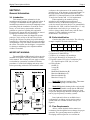
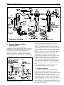
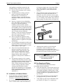
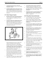
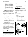
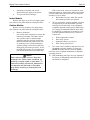
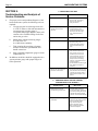
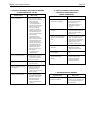
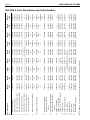
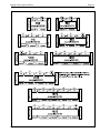
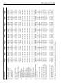
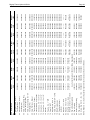
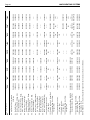
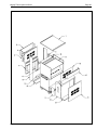
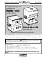
Installation and Operation Instructions
Document 1049E
Installation and Operation
Instructions for
Mighty Therm
Hydronic Boilers
Models HH and PH
Sizes 500-1825
These instructions are to be stored in the pocket provided on the boiler
FOR YOUR SAFETY: This product must be installed and serviced by a professional service technician,
qualified in hot water boiler installation and maintenance. Improper installation and/or operation could
create carbon monoxide gas in flue gases which could cause serious injury, property damage, or death.
Improper installation and/or operation will void the warranty.
WARNING
If the information in this manual is not followed exactly, a fire or explosion may result
causing property damage, personal injury or loss of life.
H0117400E
Do not store or use gasoline or other flammable vapors and liquids in the vicinity of this or
any other appliance.
WHAT TO DO IF YOU SMELL GAS
• Do not try to light any appliance.
• Do not touch any electrical switch; do not use any phone in your building.
• Immediately call your gas supplier from a nearby phone. Follow the gas supplier's
instructions.
• If you cannot reach your gas supplier, call the fire department.
Installation and service must be performed by a qualified installer, service agency, or gas
supplier.
A subsidiary of BRADFORD WHITE
LAARS HEATING SYSTEMS
Page 2
TABLE OF CONTENTS
SECTION 1.
General Information
1A.
1B.
1C.
1D.
1E.
1F.
Introduction ................................................... 3
Boiler Identification ....................................... 3
Flow Requirements ....................................... 3
Variable Water Flow Systems ....................... 4
Warning Regarding Chilled
Water Systems ............................................. 5
Freeze Protection ......................................... 5
SECTION 2.
Installation
2A.
2B.
2B-1.
2B-2.
2C.
2D.
2E.
2F.
2G.
Boiler Placement .......................................... 6
Installation of Indoor Boilers .......................... 6
Combustion Air Supply ................................. 6
Venting ......................................................... 8
Installation of Outdoor Boilers ....................... 9
Gas Supply and Piping ................................. 9
Electrical Wiring .......................................... 10
Water Piping of System .............................. 11
Filling Fully-Connected System ................... 11
SECTION 3.
Operation
3A.
3B.
3C.
3D.
3E.
Controls - General ...................................... 12
Initial Start-Up ............................................. 13
To Start Up System .................................... 13
To Turn Off Boiler ....................................... 14
To Shut Down System ................................ 14
SECTION 4.
Maintenance
................................................................... 14
SECTION 5.
Troubleshooting and Analysis of
Service Problems
................................................................... 16
SECTION 6.
Parts Descriptions and
Order Numbers
................................................................... 18
SECTION 7.
Outdoor Parts Descriptions and
Order Numbers
................................................................... 26
SECTION 8.
Optional Parts Descriptions and
Order Numbers
................................................................... 28
Mighty Therm Hydronic Boiler
SECTION 1.
General Information
1A. Introduction
This manual provides information for the
installation and operation of Laars hydronic boilers. It
is strongly recommended that all application and
installation procedures be reviewed completely before
proceeding with the installation. Consult the Laars
factory, or local factory representative with any
problems or questions regarding this equipment.
Experience has shown that most problems are caused
by improper installation not system design.
Some accessory items are shipped in separate
packages. Verify receipt of all items listed on the
package slip. Inspect everything for possible damage
upon delivery, and inform the carrier of any shortages
or impairments. Any such claims should be filed with
the carrier. The carrier, not the shipper, is responsible
for shortages and damage to the shipment whether
visible or concealed.
IMPORTANT WARNING:
The model HH and PH hydronic boilers must be
installed in accordance with the procedures outlined
in this manual. The warranty does not apply to boilers
not installed or operated in accordance with these
procedures. Consult local building and safety codes
before proceeding with work. The installation must
Page 3
conform to the requirements of the authority having
jurisdiction or, in the absence of such requirements, to
the latest edition of the National Fuel Gas Code;
ANSI Z223.1, National Electrical Code ANSI/NFPA
70 and/ or in Canada CAN 1 -13149 requirement.
When required by the authority having
jurisdiction, the installation must conform to
American Society of Mechanical Engineers safety
codes for controls and safety devices for automatically
fired boilers No. CSD-1, and in Canada CGA 3.3. Any
modification to the boiler, its gas controls, gas
orifices, wiring or draft diverter may void the Laars
warranty. If field conditions require such
modifications, consult factory.
1B. Boiler Identification
Consult rating plate on the boiler. The following
example simplifies the boiler identification.
1
2
3
4
5
6
PH
1670
I
N
09
L
(1)
(2)
(3)
(4)
(5)
Basic boiler model (see descriptions below).
Input rate X 1000 BTU/hr.
Indoor (1) or Outdoor (E) installation.
Gas type: Natural (N) or Propane (P).
Ignition system: I.I.D. (09) or continuous pilot
(16). Special option: I.I.D. (04) 115 volts.
(6) Firing modes:
On/Off (C)
2-stage (K)
4-stage (L)
Mechanical Modulation (H)
Motorized Modulation (F)
Motorized On/Off (R)
Motorized 2-stage (T).
Model HH hydronic heating boilers. There must
be a field installed pump to circulate water.
Model PH hydronic heating boilers are basically
the same as the HH models except that the PH boilers
come with integrally mount pumps. Pumps are sized
for pressure drop through the heat exchanger and short
runs of pipe for primary-secondary systems.
Laars hydronic boilers are available in two
configurations: an indoor version and an outdoor
version. Both are available from the factory (see
Figure 1).
1C. Flow Requirements
Figure 1. Boiler Configuration.
All low volume hydronic boilers must have
continuous flow through the heat exchanger for proper
operation. The system pump must be capable of
developing sufficient pressure to overcome the
LAARS HEATING SYSTEMS
Page 4
Design Temperature Rise Across The Boiler
20°F 11°C
Indoor
Sizes
Outdoor
Sizes
500
—
600
—
715
—
850
—
1010
—
1200
—
1430
—
1670
—
1825
—
—
500
—
600
—
715
—
850
—
1010
—
1200
—
1430
—
1670
—
1825
Flow
GPM l/s
Ft.
38
41
49
49
56
58
66
69
79
82
94
98
112
117
*
*
*
*
1.4
1.7
2.3
2.3
2.5
3.2
3.4
3.6
4.7
5.0
6.5
6.9
8.9
9.5
*
*
*
*
2.4
2.6
3.1
3.1
3.5
3.7
4.2
4.4
5.0
5.2
5.9
6.2
7.1
7.4
*
*
*
*
25°F 14°C
H/L
Flow
GPM l/s
m
0.4
0.5
0.7
0.7
0.8
1.0
1.0
1.1
1.4
1.5
2.0
2.1
2.7
2.9
*
*
*
*
31
33
39
39
45
47
53
55
63
66
75
78
89
93
102
109
114
119
2.0
2.1
2.5
2.5
2.8
3.0
3.3
3.5
4.0
4.2
4.7
4.9
5.6
5.9
6.4
6.9
7.2
7.5
Ft.
30°F 17°C
H/L
1.1
1.1
1.6
1.6
1.9
2.2
2.5
3.1
3.4
3.6
4.8
4.9
6.5
6.7
8.8
9.1
10
10.4
m
0.3
0.3
0.5
0.5
0.6
0.7
0.8
0.9
1.0
1.1
1.5
1.5
2.0
2.0
2.7
2.8
3.0
3.2
Flow
GPM l/s
26
27
32
32
37
39
44
46
53
55
62
65
74
78
85
91
95
99
1.6
1.7
2.0
2.0
2.3
2.5
2.8
2.9
3.3
3.5
3.9
4.1
4.7
4.9
5.4
5.7
6.0
6.2
Ft.
35°F 19°C
H/L
0.9
0.9
1.1
1.1
1.5
1.6
2.0
2.2
2.7
3.1
3.7
3.6
5.0
5.0
6.7
6.8
8.0
8.3
m
0.3
0.3
0.3
0.3
0.5
0.5
0.6
0.7
0.8
0.9
1.1
1.1
1.5
1.5
2.0
2.1
2.4
2.5
Flow
GPM l/s
22
23
28
28
32
33
38
39
45
47
53
56
64
67
73
78
81
85
1.4
1.5
1.8
1.8
2.0
2.1
2.4
2.5
2.8
3.0
3.3
3.5
4.0
4.2
4.6
4.9
5.1
5.4
Ft.
H/L
0.6
0.7
0.9
0.9
1.0
1.1
1.4
1.6
1.9
2.2
2.6
3.1
3.5
3.7
4.7
5.0
5.5
5.7
m
0.2
0.2
0.3
0.3
0.3
0.3
0.4
0.5
0.6
0.7
0.8
0.9
1.1
1.1
1.4
1.5
1.7
1.7
*Consult factory for recommendations
Table 1. Flow Requirements.
resistance of the boiler plus the entire circulating
system at the designated GPM (see Table 1). The
temperature rise across the boiler should never exceed
40°F (22°C). Primary-secondary pumping is the most
effective way to assure proper flow through the boiler
resulting in longer boiler life and greater system
efficiency (see Figure 2).
1D. Variable Water Flow Systems
Heating systems using zone valves, zone pumps
or 3-way valves can experience reduced water flow
through the boiler. This can result in an excessive
water temperature rise and unstable boiler operation.
If the system water flow is variable, it must not be
allowed to fall below 30% of full flow. The boiler
must be equipped with staged or modulated fire with
the temperature sensor installed in the outlet water.
State variable flow when ordering. Laars recommends
primary-secondary pumping for all variable flow
systems. Primary-secondary pumping is mandatory
for variable flow systems where minimum flows are
less than 30% of full flow conditions. The boiler
pump in a primary-secondary system maintains
constant flow through the boiler even though the
system flow is variable. In a primary-secondary
system the pressure drop of the boiler is not added to
the system (see Figure 2).
A Special Note About 3-Way Water Valves
3-way water valves (2 position or proportional)
are sometimes used to divert water around a boiler
and control the temperature of water being supplied to
the system. Valves installed in this manner must be
supplied with an end switch or some other suitable
control to shut off the boiler when the flow is reduced
to 30%. The boiler must be supplied with staged or
modulated fire as indicated in Section 1D, Variable
Water Flow Systems.
It is often possible to accomplish excellent water
temperature control without 3-way valves through
proper application of staged or modulated firing
systems. Consult the factory or local Laars
representative for assistance with such systems.
System Pressure Requirements
The model HH and PH boilers are designed to
operate on closed, pressurized systems. A minimum of
12 psi should be maintained on the system where
boiler supply water temperatures are 200°F (93°C) or
less. If higher temperatures are required, the minimum
system pressure should be at least 15 psi above the
water vapor pressure corresponding to the elevated
water temperature.
The hydronic boilers are not suitable for open
systems unless the supply water temperatures are kept
below 180°F (82°C), and minimum of 5 psi static
head is maintained within the boiler.
Mighty Therm Hydronic Boiler
Page 5
Figure 2. Typical Schematic for a Primary-Secondary System.
1E. Warning Regarding Chilled
Water Systems
When a boiler is connected to an air
conditioning system where the same water is used for
heating and cooling, chilled water must be prevented
from entering the boiler. When changing such a
system from cooling to heating, the chilled water
should be allowed to circulate through the building
(after the chiller has been turned off) for a period long
Suggested Wiring Diagram For Tempering System Water
at Change-over From Heating to Cooling.
enough for the water to warm up to at least 70°F
(21°C) before the water is allowed to flow into the
boiler. It is equally important to prevent hot water
from entering the chiller. The system shown in Figure
3 is suggested to make sure that the system water is
neither too hot nor too cold when a changeover from
heating to cooling, or vice versa, takes place. When a
boiler is connected to heating coils located in air
handling units (where they may be exposed to
refrigerated air circulation), the boiler piping system
shall be equipped with a flow control valve or other
automatic means to prevent gravity circulation of
chilled water through the boiler. Chilled water in the
boiler will create condensation on the boiler tubes
which will drip on the burners and may extinguish the
pilot.
Boilers installed in violation of either of the
above requirements may void the warranty.
1F. Freeze Protection
Figure 3. Boiler-Chiller Installation.
Boiler installations are not recommended in
areas where the danger of freezing exists unless
proper precautions are taken for freeze protection. The
preferred method of freeze protection is by
maintaining a mixture of no more than 50% properly
inhibited HVAC glycol. This mixture will protect the
boiler to temperatures of about -35°F (-37°C). To get
the desired temperature rise across the boiler when
this mixture is used, increase the water flow by 15%
above the original recommendation. Increase the head
loss requirement by 20%.
LAARS HEATING SYSTEMS
Page 6
SECTION 2.
Installation
1.
2A. Boiler Placement
The boiler must be placed to provide specific
clearances on all sides for maintenance and
inspection. There must also be minimum distances
maintained from combustible surfaces. These
clearances also apply to non-combustible materials,
because the boiler requires air circulation for proper
operation.
Boiler should be mounted on a level surface. An
integral combustible flooring base is provided as
standard equipment on all outdoor models. Indoor
models can be installed on a combustible floor with a
special base assembly which is available from the
factory, or with a base that complies with local code
requirements. See rating plate for part number of the
base assembly.
Do not install boiler on carpeting.
Under the National Fuel Gas Code, ANSI
Z223.1, it is permissible to place the boiler on floors
other than non-combustible when the installation
complies with the American Insurance Code. Figures
5, 6, 7, and 8 show common installation on
combustible flooring.
2B. Installation of Indoor Boilers
1.
Locate the boiler to provide adequate
clearance for inspection and service on all sides
(see Table 2). We recommend minimums of 24"
from front (for proper access to and service of
controls) and 18" at water connection end. For
alcove installation, see Figure 9.
Clearance
From
Top
Water Conn. Side
Opposite Side
Front
Rear
Vent Pipe*
Hot Water Pipes
Indoor
inches mm
Outdoor
inches mm
30
762
12
305
6
152
Alcove
8
203
6
152
Per Code
unobstruct
24
610
24
610
Unobstruct
24
610
—
Per Code
*1" when using type B Vent (refer to Manufacturer's
Instructions
Table 2. Minimum Boiler Clearances
From Combustible Surfaces.
2.
Install the boiler on a waterproof floor with an
adequate floor drain and a 6" (152mm)
minimum curb on all four sides to protect the
building if boiler repairs are required. The
manufacturer will not be held liable for any
water damage in connection with this boiler.
2.
2B-1. Combustion Air Supply
The boiler location must provide sufficient air
supply for proper combustion and ventilation of
the surrounding area as outlined in the latest
edition of ANSI standard Z223.1 and/or in
Canada CAN 1 - B1 49 requirements, and any
local codes that may be applicable. Inadequate
combustion air supply may result in incomplete
combustion, sooting of the heat exchanger, and
unsafe operation of the boiler.
(a.) In the United States, the general
requirements specify that boiler rooms should be
provided with two permanent air supply
openings communicating directly through the
wall to outside air; one within 12 inches
(305mm) of the ceiling, and the other within 12
inches (305mm) of the floor. Each opening
should have a minimum free area of one square
inch per 4,000 BTUH input of the total input
rating of all appliances in the enclosed area. See
Table 3 for recommended air supply for each
model. An improperly ventilated equipment
room can get excessively hot and cause
accelerated deterioration of controls and
electrical components.
Boiler
Model
500
600
715
850
1010
1200
1430
1670
1825
Each Opening*
Sq. Inches Sq. cm
125
150
179
213
253
300
358
418
457
806.5
967.8
1154.9
1374.3
1632.4
1935.6
2309.8
2696.9
2948.6
*Net Free Area in Square Inches
Area indicated is for one of two openings; one at
floor level and one at the ceiling, so the total net
free area could be double the figures indicated.
For special conditions refer to the latest edition of
ANSI Z223.1.
Consult factory if not communicating directly
through the walls with the outdoors.
Note: Check with louver manufacturers for net
free area of louvers. Correct for screen
resistance to the net free area if a screen is
installed. Check all local codes applicable to
combustion air.
Table 3. Minimum Recommended
Air Supply to Boiler.
Mighty Therm Hydronic Boiler
Page 7
Figure 7. Typical Boiler Installation on Roof Using a
4 x 4 Stringer.
Figure 4. Base for Combustible Floors.
Figure 8. Installation on Concrete Blocks or Tile.
Figure 5. Typical Boiler Installation on Concrete Slab.
3.
Figure 6. Typical Boiler Installation on Raised Platform
(Wood).
(b.) In Canada, consult local building and safety
codes or, in the absence of such requirements,
follow CGA requirements and/or CAN 1 - B149
standard. (Table 3 does not apply).
Exhaust Fans or Vents: Any equipment which
exhausts air from the boiler room can deplete the
combustion air supply or reverse the natural
draft action of the venting system.
The boiler must be completely isolated and this
could cause flue products to accumulate in the
room. Additional air must be supplied to
compensate for such exhaust. The information in
Table 3 is not applicable in installations where
exhaust fans or blowers of any type are used.
Such installations must be designed by qualified
engineers.
LAARS HEATING SYSTEMS
Page 8
2.
3.
4.
5.
Figure 9. Alcove Installation.
6.
4.
5.
1.
If a blower or fan is used to supply air to the
heater room, the installer should make sure it
does not create drafts which could cause
nuisance shutdowns of the pilot. If a blower is
necessary to provide adequate combustion air to
the boiler, a suitable switch or equivalent must
be wired into the boiler control circuit to prevent
the boiler from firing unless the blower is
operating.
The boiler must be completely isolated and
protected from any source of corrosive chemical
fumes such as trichlorethylene, perchlorethylene,
chlorine, etc.
2B-2. Venting
Laars boilers have built-in draft diverters for
natural draft operation and must not be
connected to any portion of a mechanical draft
system under positive pressure. The flue outlet
must be connected to a clear, unobstructed vent
of adequate capacity ending above the highest
point of the building with an approved vent cap.
The venting system should be installed
according to the latest edition of ANSI Z223.1
and/or, in Canada, CAN1-13149 requirement
and any local codes having jurisdiction.
IMPORTANT NOTE: Do not use sheet metal
screws at the snap lock joints of Type B gas vents.
7.
8.
Do not weld or fasten the vent pipe to the boiler
draft hood. The weight of the stack must not rest
on the boiler. The draft hood and boiler top must
be easily removable for normal boiler service
and inspection.
Avoid using long horizontal runs of the vent
pipe, and too many 90° elbows, reductions or
restrictions. Horizontal runs should have at least
a 1/4" rise per foot in the direction of flow. A
vent connector should be supported for the
design and weight of the material used to
maintain clearances and prevent physical
damage and separation of joints.
Avoid ending heater vents near air conditioning
or air supply fans. The fans can pick up exhaust
flue products from the boiler and return them
inside the building, creating a possible health
hazard. A minimum of 4 feet (1.2m) horizontal
distance must be maintained from electrical
meters, gas meters, and relief equipment.
Always use double-wall or insulated vent pipe
(Type B or equivalent). In cold weather,
uninsulated outside vents can chill the rising flue
products, blocking the natural draft action of the
venting system. This can create a health hazard
by spilling flue products into the boiler room.
Avoid oversize vent piping or extremely long
runs of the pipe which may cause excessive
cooling and condensation. Rule of Thumb: The
total length of the vent, including the connector
and any offset, should not exceed 15 feet (4.6m)
for every inch of vent diameter. Longer total
lengths shown in venting tables are based on
maximum capacity, not condensation factors.
When the installation of a draft fan is necessary
in connecting a venting system to a Laars boiler,
the installation should be engineered by
competent personnel following good engineering
practices. The draft fan supplier should be
consulted for correct size. The installation
should be in accordance with the latest edition of
ANSI Z223.1 and/or, in Canada, CAN 1-B149
requirement and any local codes having
jurisdiction. When a draft fan is installed, a
suitable draft switch must be wired into the
boiler control circuit at terminal designated
“Field Interlock” to prevent firing of the boiler
unless a positive draft has been established.
When an existing boiler is removed from a
common venting system, the common venting
system is likely to be too large for proper venting
of the appliances remaining connected to it.
At the time of removal of an existing boiler, the
following steps shall be followed with each
appliance remaining connected to the common
venting system placed in operation, while the
Mighty Therm Hydronic Boiler
other appliances remaining connected to the
common venting system are not in operation.
(a) Seal any unused openings in the common
venting system.
(b) Visually inspect the venting system for
proper size and horizontal pitch and
determine there is no blockage or
restriction, leakage, corrosion and other
deficiencies which could cause an unsafe
condition.
(c) Insofar as is practical, close all building
doors and windows and all doors between
the space in which the appliances
remaining connected to the common
venting system are located and other spaces
of the building. Turn on clothes dryers and
any appliance not connected to the common
venting system. Turn on any exhaust fans,
such as range hoods and bathroom
exhausts, so they will operate at maximum
speed. Do not operate a summer exhaust
fan. Close fireplace dampers.
(d) Place in operation the appliance being
inspected. Follow the lighting instructions.
Adjust thermostat so appliance will operate
continuously.
(e) Test for spillage at the draft hood relief opening after 5 minutes of main burner operation.
Use the flame of a match or candle, or smoke
from a cigarette, cigar or pipe.
(f) After it has been determined that each
appliance remaining connected to the
common venting system properly vents
when tested as outlined above, return
doors, windows, exhaust fans, fireplace
dampers and any other gasburning
appliance to their previous conditions of
use.
(g) Any improper operation of the common
venting system should be corrected so the
installation conforms with the latest edition
of the National Fuel Gas Code, ANSI
Z223.1. When resizing any portion of the
common venting system, the common
venting system should be resized to
approach the minimum size as determined
using the appropriate tables in Appendix G
in the National Fuel Gas Code,
ANSI Z223. 1.
2C. Installation of Outdoor Boilers
1.
2.
Locate the boiler to provide the minimum
clearances as listed in Table 2, “Boiler
Clearances.” See Service Clearance, 2 B.1.
Do not place the boiler in an enclosure or wall
recess. Avoid locations where wind deflection
Page 9
3.
off structures might cause a down draft. When
such wind conditions are possible, place the
boiler at least three (3) feet (0.9m) from the
structures.
Never install the boiler under any kind of roof
overhang. Do not place the boiler below or
adjacent to any doors, windows, louvers, grills,
etc. which connect in any way with an inhabited
area of a building. This includes other structures
such as garages or utility rooms (see Figure 10).
Figure 10. Incorrect Outdoor Installation.
4.
Although these models are AGA designed
certified for outdoor installations, such
installations are not recommended in areas
where the danger of freezing exists unless proper
precautions are taken for freeze protection.
Caution
Outdoor installations are not recommended
in areas where the danger of
snow blockage exists.
2D. Gas Supply and Piping
Review the following instructions before
proceeding with the installation.
1. Verify that the boiler is fitted for the proper type
of gas by checking the rating plate. Laars boilers
are normally equipped to operate below a 2000
foot (610m) altitude. Boilers equipped to operate
at higher altitudes have appropriate stickers or
tags attached.
2. Use the figures in Table 4 to provide adequate
gas piping from the gas meter to the boiler.
3. A trap (drip leg) must be provided ahead of the
gas controls (see Figure 11). A manual gas
LAARS HEATING SYSTEMS
Page 10
Distance from Gas Meter
or Last Stage Regulator
Size
0-100'
(0-30.5m)
100-200'
(30.5-61m)
200-300'
(61-91.4m)
500
600
715
850
1010
1200
1430
1670
1825
1-1/2"
1-1/2"
2"
2"
2"
2-1/2"
2-1/2"
2-1/2"
2-1/2"
2"
2"
2"
2-1/2"
2-1/2"
3"
3"
3"
3"
2"
2-1/2"
2-1/2"
2-1/2"
3"
3"
3"
3"
3-1/2"
Note: These figures are for Natural Gas (.65 Sp. Gr.), and are
based on 1/2" water column pressure drop. Check supply
pressure with a manometer, and local code requirements for
variations. For LPG, reduce pipe diameter one size, but maintain
a 1" minimum diameter. A normal number of Tees and elbows
have been taken into allowance.
Table 4. Gas Piping Sizes.
supply pressure. Low gas pressure could be an
indication of an undersized gas meter and/or
obstructed gas supply line.
6. The correct burner manifold gas pressure is
stamped on the rating plate. The regulator is
preset at the factory and normally requires no
further adjustment.
7. The gas manifold and control assembly was
tested and conform to the safe lighting and other
performance criteria specified in the latest
editions of ANSI Z21.13 and CGA 3.3 Low
Pressure Boiler Standard.
8. Before operating the boiler, the complete gas
supply system and all connections must be tested
for leaks using a soap solution. Do not use raw
flame.
Caution
Since some leak test solutions (including soap
and water) may cause corrosion or stress
cracking, the piping must be rinsed with water
after testing, unless it has been determined
that the leak test solution is noncorrosive.
2E. Electrical Wiring
Electrical diagrams are included with the packet
provided with each unit.
Figure 11. T-Fitting Sediment Trap Installation.
4.
5.
shutoff valve must also be provided for service
convenience and safety. Check the local codes.
The boiler and its individual shutoff valve must
be disconnected from the gas supply piping
system during any pressure testing of that system
at test pressures in excess of 1/2 psig. The boiler
must be isolated from the gas supply piping
system by closing its individual manual gas
shutoff valve during any pressure testing of the
gas supply piping system at test pressures equal
to or less than 1/2 psig.
Provide gas supply pressure to the boiler as
follows:
Natural Gas
Min. (inches
water column)
Max. (inches
water column)
LPG
Per Rating Plate
9
WARNING
The boiler must be electrically grounded in
accordance with the most recent edition of the
National Electrical Code, ANSI/NFPA 70. In
Canada, all electrical wiring to the boiler should
be in accordance with the Canadian Electrical
Code, CSA C22.1 Part 1. Do not rely on the
gas or water piping to ground the metal parts
of the heater. Frequently, plastic pipe or
dielectric unions isolate the boiler electrically.
Service and maintenance personnel who work
on or around the boiler may be standing on wet
floors and could be electrocuted by an
underground boiler.
1.
14
Note: The boiler and all other gas appliances
sharing the boiler gas supply line must be firing at
maximum capacity to properly measure the inlet
2.
Check boiler wiring and pump for correct
voltage, frequency and phase. If the pump circuit
is other than 115V, check to see that the boiler is
provided with an appropriate transformer.
Wire the boiler and pump exactly as shown in
the wiring diagram supplied with the boiler.
Mighty Therm Hydronic Boiler
3.
4.
The pump and boiler must be electrically
interlocked so the boiler cannot come on unless
the pump is running.
All field installed electrical safety devices and
all field installed devices (draft switches, relays,
timers, outdoor temperature reset devices, etc.)
can be connected to the heater wiring at points
shown in the wiring diagram designated “Field
Interlock.”
2F. Water Piping of System
1.
2.
Be sure to provide valves at the inlet and outlet
of the boiler so it can be readily isolated for
service. A butterfly or similar type of valve is
recommended.
The pressure relief valve installed in the tapped
opening provided in the outlet header (See
Figure 12), must be piped, but not fastened, to a
drain or floor sink. The drain pipe must be the
same size as the valve outlet and must pitch
downward from the valve.
Pressure
Relief Valve
Figure 12. Pressure Relief Valve Location.
3.
4.
Special attention must be given to relief valve
settings in installations where the boiler is
located on the ground floor of a tall building,
The static pressure of the system is elevated and
could cause the relief valve to leak. Where no
special setting of the relief valve is ordered, the
factory will furnish a 75 psi setting. Never
reduce the relief valve openings.
Pressure relief valve lever must be tripped at
least once a year to insure that waterways are
clean. When manually operating lever, water
will discharge through drain line. Precautions
must be taken to avoid contact with hot water
and water damage.
The weight of all water and gas piping should be
supported by suitable hangers or floor stands.
Page 11
5.
6.
7.
Check piping diagrams with local applicable
plumbing, heating and building safety codes.
A boiler installed above radiation level must be
provided with a low water cutoff device either as
part of the boiler or at the time of boiler
installation.
Install manual and/or automatic bleeding devices
at high points in the system to eliminate air.
Install a correctly sized air charger and tank
drainer, as appropriate.
2G. Filling Fully-Connected System
1.
Close all bleeding devices and open make-up
water valve. Allow system to fill slowly.
2. If make-up water pump is employed, adjust
pressure switch on pumping system to provide a
minimum of 12 psi at the highest point in the
heating loop.
3. If a water pressure regulator is provided on the
make-up water line, adjust the pressure regulator
to provide at least 12 psi at the highest point in
the heating loop.
4. Open bleeding devices on all radiation units at
the highest points in the piping throughout the
system, unless automatic air bleeders are
provided at such points.
5. Run system circulating pump for a minimum of
30 minutes with the boiler shut off.
6. Open all strainers in the circulating system and
check for debris.
7. Recheck all air bleeders as described in Step 4
above.
8. Check liquid level in expansion tank. With the
system full of water and under normal operating
pressure, the level of water in the expansion tank
should not exceed 1/4 of the total, with the
balance filled with air.
9. Start up boiler according to procedure described
in Section 3B. Operate the entire system,
including the pump, boiler, and radiation units
for one (1) hour.
10. Recheck the water level in the expansion tank. If
the water level exceeds 1/4 of the volume of the
expansion tank, open the tank drainer and drain
to that level.
11. Shut down the entire system and vent all
radiation units and high points in the system
piping as described in Step 4 above.
12. Close make-up water valve and check strainer in
pressure reducing valve for sediment or debris
from the make-up water line. Reopen make-up
water valve.
LAARS HEATING SYSTEMS
Page 12
13. Check gauge for correct water pressure and also
check water level in system. If the height
indicated above the boiler insures that water is at
the highest point in the circulating loop, then the
system is ready for operation.
14. Within three (3) days of start-up, recheck all air
bleeders and expansion tank as described in
Steps 4 and 8 above.
2.
SECTION 3.
Operation
3A. Controls - General
1.
Electronic Ignition Controls:
a. Intermittent Ignition:
Pilots are automatically lit when the
operating aquastat calls for heat (System #4
and #9) The unit performs its own safety
check and opens the main valves only after
the pilot is proven to be lit. Whenever the
pilot flame is interrupted, the main gas
valve closes within 0.8 seconds.
b. Electronically Supervised Standing Pilot
System (System #16):
When pilot flame fails, the ignition control
module responds in less than 0.8 seconds
and provides 100% safety shutdown.
Figure 13. Typical Controls Locations.
Operating Controls:
a. Electrically Operating Controls:
Single, two-stage, four-stage or modulating
aquastats are provided in models HH and
PH boilers to control the desired service
water temperature. The temperature
sensing bulb is located in the boiler inlet.
b. Modu-Snap Valves (Mechanical
Modulation Only):
These valves are furnished in addition to
the main electric gas valve. Each valve has
a remote capillary bulb immersed in a well
at the outlet header to maintain a constant
outlet temperature. Consult Table 5 for
desired temperature setting.
Dial No.
1
2
3
4
5
6
7
8
9
Temp °F 120 135 150 165 180 195 210 225 240
Temp °C 49 57 66 74 82 91 99 107 116
Table 5. Modu-Snap Temperature Settings
3.
High Limit Controls:
The manual reset high limit switches are
provided as standard equipment on all
boilers. Automatic reset switches are
optionally provided. The temperature
sensing bulb of the switch is always located
in the boiler outlet. Burners will
automatically shut down whenever
overheating of water occurs.
Mighty Therm Hydronic Boiler
4.
5.
Flow Switch:
Standard on all models: Models HH and
PH, the switch is mounted in the outlet
“tee” connection. The flow switch shuts
down all burners in case of pump failure.
Low Water Cut Off (Optional):
The low water cut off automatically shuts
off boiler whenever water level drops
below probe. Located at boiler inlet (model
PH) and at return header (model HH).
3B. Initial Start-Up
Lighting: Safe lighting and other performance
criteria were met with the gas manifold and control
assembly provided on the boiler when it underwent
tests specified in the ANSI Z21.13 standard.
Before placing the boiler in operation, be certain
that the boiler is filled with water and all air is purged
from the system. Once the boiler is connected to the
gas supply, the automatic safety shutoff devices must
be checked.
1. Before beginning the tests, make sure the main
manual gas valve, and any other boiler firing
valves are in the “OFF” position.
2. Make sure the boiler’s power switch is in the
“ON” position. After placing the manual pilot
gas valve in the open position and resetting all
safety devices, (high limit, pressure switch, lowwater cutoff, etc.) pilot(s) can be lit following
the procedure located on the boiler rating plate.
3. Once the pilot(s) is lit and has been established
for five minutes, the flame failure response time
should be checked as follows:
Systems 9 and 4 - (Intermittent ignition), natural
gas only: With this system pilots are automatically lit
when the operating controls call for heat. If the pilot
flame fails for any reason, the main valve is shut off
within one second and the pilot spark ignition is
initiated until the pilot flame has been reestablished.
On propane systems, unit locks out for safety. This
sequence should be checked by turning off the manual
pilot gas valve, and, at the same time, monitoring the
audible sparking at the pilot burner and signal
interruption to the main valve.
Page 13
interrupted. The signal interruption can be detected
either with a test light or a voltmeter. The response
time should never exceed one second.
4. With the pilots lit, initial activation of the main
burners can be achieved by slowly opening the
main valve. The result should be a smooth
lighting of the main burners.
Hi-Limit Checkout :
After running the boiler for a long enough
period, bring the water temperature within the range
of the hi-limit and slowly back off the high limit
setting until the boiler shuts off. The main burners
should reignite when the hi-limit is reset and turned
back up to its original setting. The boiler should now
run until it shuts off automatically on operating
aquastat.
3C. To Start Up System:
1.
Start Up Boiler
Be certain system pump is running, then proceed
as follows:
a. Turn off main electrical switch.
b. Turn off all manual gas valves and wait
five minutes (see Figure 14).
c. Set operating control to lowest setting.
d. Slowly turn manual gas valve to “ON”.
e. Reset all safety valve switches (manual
reset high limit and low water cut off).
Caution
Propane gas is heavier than air and sinks to
the ground. Exercise extreme care in lighting
the boiler when so equipped.
System 16 - (Electronically supervised standing
pilot system): Extinguish the pilot flame by placing
the manual pilot valve in the closed position, and at
the same time, begin recording the time it takes for the
output signal from the electronic ignition control to be
Figure 14. Gas Manual Valves.
LAARS HEATING SYSTEMS
Page 14
f.
g.
h.
Open manual pilot valve. Turn on main
electrical switch.
Set temperature controller to desired
temperature. Pilot will light automatically
to ignite main burners whenever the
aquastat calls for heat.
For standing pilot system, press on pilot
relay knob (see Figure 15), light pilot and
keep relay knob depressed for one minute
then release. Once the pilot is lit, the power
is supplied through the aquastat to the main
gas valve.
remove drain plug in the bottom of front header cover.
Drain every part of system subject to freezing
temperature.
SECTION 4.
Maintenance
1.
2.
3.
Lubricate the water circulating pump (see
instructions found on the pump).
If a strainer is employed in a pressure reducing
valve or in piping, clean it every six (6) months.
At start-up and every six (6) months thereafter,
the pilot and main burner flame should be
observed for proper performance (see Figure 16).
See attached lighting and shut-down instructions
for proper pilot flame pattern). If flame has the
appearance of “sooting” tips, check for debris
near orifices. Call serviceperson.
Figure 15. Pilot Safety Relay.
2.
3.
To set the temperature and high-limit controls:
a. Set the temperature controller at the system
design temperature.
b. Set the high-limit to 40-50°F above
temperature controller setting.
c. Models with Mechanical Modulation
Set the temperature controller (Modu-Snap
valve) dial to the desired water temperature
(see Table 5).
Minimum input rates:
The low firing rate setting must be equal to or
greater than the specified minimum input rating
as shown on the appliance rating plate. Laars’
boilers use gas valves which are factory set to
provide an input on low fire that meet or exceed
the specified minimum.
3D. To Turn Off Boiler:
1.
2.
Turn off main electric switch.
Close all manual gas valves.
3E. To Shut Down System:
To shut down boiler, turn off all manual gas
valves and electrical disconnect switches. Whenever
danger of freezing exists, shut off water supply and
Figure 16. Main Burner Flame Pattern.
4.
5.
6.
7.
Inspect the venting system for obstruction,
leakage and corrosion at least once each year.
Keep boiler area clear and free from combustible
material, gasoline and other flammable vapors
and liquids (see Table 2 for minimum
clearances).
Be certain all combustion air and ventilation
openings are unobstructed.
Check for fouling on the external surfaces of the
heat exchanger every six months. (NOTE: After
installation and first start-up, check the heat
exchanger for fouling after the following periods
of operation: 24 hours, 7 days, 30 days, 90 days,
and once every six months thereafter).
Fouling on the external surfaces of the heat
exchanger is caused by incomplete combustion
and is a sign of combustion air and/or venting
problems. As soon as any fouling is observed,
the cause of the fouling should be corrected (see
Section 5, Troubleshooting Guide). The heat
exchanger can be checked by locating a mirror
under the burners with a flashlight. An alternate
method is to remove the venting and top panel as
necessary to inspect from above. Also check the
vent system for defects at this time.
Mighty Therm Hydronic Boiler
a.
b.
If cleaning is required, shut off all
electrical and gas supply to the heater.
To expose the heat exchanger:
Indoor Models:
Remove flue pipe, top of unit, rear upper jacket,
flue collector rear panel and heat exchanger baffles.
Outdoor Models:
Remove vent top assembly, rear upper jacket,
flue collector rear panel and heat exchanger baffles.
c. Remove all burners:
It is usually more convenient to remove the
burner tray assembly. Disconnect sensor
wire, ignition cable (or thermocouple
generator) and pilot gas line. Disconnect
manifold inlet union(s). Remove the four
(4) retaining screws. Grasp burner/pilot
assembly firmly at the front. Push it back,
disengaging it from the gas orifice. Lower
the front of the burner (to avoid damaging
pilot shield) then remove the burner tray.
Caution
Black carbon or green soot on a dirty heat
exchanger can, under certain conditions, be
ignited by a random spark or open flame. To
prevent this unlikely occurrence, dampen the
soot deposits with wet brush or fine water
spray before servicing or cleaning the heat
exchanger.
Page 15
With a wire brush, remove soot and loose scale
from heat exchanger. Clean fallen debris from bottom
of heater. Make sure burner ports are clear and pilot
assembly is free of debris.
d. Reassemble in reverse order: Be sure the
heat exchanger baffles are replaced.
8. The gas and electric controls installed on boilers
are engineered for both dependable operation
and long life, but the safety of this equipment
completely depends on their proper functioning.
It is strongly recommended that the basic items
be checked by a competent serviceperson every
year and replaced when necessary. The basic
controls are:
a. Water temperature controls.
b. Pilot safety system.
c. Automatic electric gas valve(s).
d. Flow sensing safety device.
9. Low water cutoffs should be inspected every six
(6) months, including flushing of float types.
NOTE: Warranty does not cover any damage
caused by lack of required maintenance or improper
operating practices.
10. Both modulating and stage valve are adjusted at
the factory for minimum permissible rates and
should not be readjusted.
LAARS HEATING SYSTEMS
Page 16
SECTION 5.
Troubleshooting and Analysis of
Service Problems
1.
2.
For proper service and problem diagnosis of the
heater and heater system, the following tools are
required:
a. Gas pressure test kit with range from zero
to 14 W.C. Either a slack tub manometer or
an accurate gas pressure gauge is
acceptable with proper adapters which will
connect to the available fittings in the line
and on the gas valve.
b. Multi-meter with the following ranges:
0 to 500 volts A.C.
0 to 1000 ohms continuity.
c. Tube cleaning kit consisting of reamer,
stainless steel brush, speed handle and
handle extensions.
d. Strap on digital temperature gauge to check
temperature rise.
In addition, the boiler should be equipped with a
system pressure gauge with proper ranges for
boiler operation.
3. BOILER WILL NOT FIRE.
Possible Cause
What To Do
A. Electric power is off.
A. Check to see that main power
switch is “ON.” Use testing
device to trace power to
boiler junction box.
B. Operating or safety control has
opened circuit to electric
gas valve.
B. Turn off power. Use continuity
across terminals of each
operating and safety control
switch up to the electric gas
valve. Replace defective
control.
C. Pilot flame is out.
C. Relight pilot per instruction.
D. Manual reset device has tripped. D. Follow instructions for start-up.
Reset Pilot safety and all
manual reset safety switches
and reset manual safety gas
valve.
E. No gas pressure to burners.
E. Trace gas line to service shutoff
cock. If service cock is open,
trace gas line to meter. If no
pressure is present at meter,
call for public utility service. If
gas is present in boiler inlet,
check pressures in following
sequence: (1) downstream from
pressure regulator;
(2) downstream from electric gas
valve. Replace or adjust as
necessary.
F. Electric gas valve operator is
burned out or shortened.
F. Disconnect wiring harness at gas
valve terminals. Check continuity
to actuator coil. If open circuit or
short is indicated, replace coil or
operator.
4.
PRESSURE RELIEF VALVES LEAKING
INTERMITTENTLY OR STEADILY.
Possible Cause
What To Do
A. Static pressure in system
exceeds setting of relief valve.
A. Calculate height of water in
system above boiler. Install new
valve with psi setting 25% above
required static system working
pressure. Do not exceed 160 psi.
B. Expansion tank is waterlogged
(if installed).
B. Drain expansion tank, then
reopen it to the system. Look for
leaks in expansion tank or
fittings. Calculate required
volume of expansion tank in
relation to system to determine
that tank is adequate.
Mighty Therm Hydronic Boiler
Page 17
5. BOILER IS POUNDING, KNOCKING OR EMITTING
STEAM FROM RELIEF VALVES.
Possible Cause
What To Do
6. SOOT IN FLUEWAYS OR IN TUBES,
OR NOXIOUS FUMES INDICATIVE
OF BAD COMBUSTION.
Possible Cause
A. Low or no water flow.
A. This condition is usually
caused by lack of adequate
flow through boiler.
Check the following:
(1) Is the boiler wired into
the pump circuit so that the
boiler cannot fire unless
the pump is running?
(2) Check to see that all
valves in system are open
to be sure that water can
circulate through the boiler
and the system.
(3) If the system has
automatic water valves (2way or 3-way) that can cut
off the water flow through
the boiler check to see
that they are equipped with
end-switches which shut
the boiler down when the
water flow through the
boiler is reduced by 70%
from full flow.
(4) Examine pump for
clogged impeller.
B. Low or no system pressure.
B. Clean strainer in pressure
reducing valve. Look for
closed valve water line or
a leak in the system.
C. Clogged "Y" strainer.
C. Remove strainer element
and clean screen.
D. Debris from system piping is
blocking tubes.
D. Remove header covers.
Examine all tubes and
waterways. Use new
gaskets when reassembling.
Clean out tubes.
E. Scale has formed in tubes.
E. This is always caused by
the inflow of raw water into
the system. Clean tubes
with tube cleaning kit.
Determine hardness.
Check for modified flow if
necessary.
What To Do
A. Combustion air supply to
boiler room is inadequate.
A. Check air supply opening.
Look for debris in screen or
louvre which covers
combustion air opening, or
for material blocking the
opening.
B. Stack or vent is blocked or
restrictive.
B. Look for blocked stack and
excessive number of elbows in
stack or excessive length of
horizontal runs.
C. Severe down draft is causing
spillage of flue products into
room.
C. Check for (1) proper vent cap on
stack; (2) adequate height of
stack above roof; (3) equipment
exhausting air from inside of
building; and (4) proper
installation of draft diverter.
D. Gas pressure to burners is
excessive.
D. Check gas presssure with
Manometer, and adjust
with heater firing at full rate.
E. Boiler not fitted for the fuel
being supplied.
E. See nameplate for correct
fuel.
F. Boiler installed at high
altitude without proper
derating.
F. Installations at altitudes in
excess of 2000 ft. above
sea level are subject to
jurisdiction of the local
inspection authorities.
7. WATER DRIPPING IN FIREBOX.
Possible Cause
Tub in heat exchanger has
overheated and ruptured.
What To Do
A tube failure is almost always
caused by (1) scale formation in the
tube or (2) inadequate water flow
through the boiler.
Tile Cover, Front & Rear
Baffle, Heat Exch. (Frt & Rear)
8
9
10534301
(2)
10534201
(2)
10534401
10391302
——
10391304
S0063700
S0095100
14 Flange, 2" (S00636)
Flange, 2 1/2 “ (S00635)
Flange, 2 1/2" (S00644), Bronze
15 Flange Gasket
16 Header Gasket w/Barrier
10535504
10533800
10533700
10540800
10535704
Model
850
10397500
E0025900
E0085700
19 Barrier, Water
20 Well, Aquastat
Well, Aquastat F/4 Stage
E0025900
E0085700
10397500
10338300
S0095100
S0063700
10391302
——
10391304
10364500
10364501
10535505
10533800
10533700
10540800
10535705
Model
1010
S0095100
S0063700
10391302
——
10391304
10364500
10364501
10364301
10364300
10534604
(14)
——
10534304
(4)
10534204
(4)
10534404
S0095100
S0063700
——
10391303
10391304
10364500
10364501
10364301
10364300
10534605
(14)
——
10534305
(4)
10534205
(4)
10534405
E0025900
E0085700
10397500
10338300
E0025900
E0085700
10397500
10338300
E0025900
E0085700
10397500
10338300
Use S00951 00-Cut Out Barrier
S0095100
S0063700
10391302
——
10391304
10364500
10364501
10364301
10364300
10534603
(14)
——
10534303
(2)
10534203
(2)
10534403
NOTE: Numbers in ( ) represent quantity required for each size. Quantity is one otherwise.
10338300
18 Baffle, Water Inlet
17 Header Gasket
10364500
10364501
13 Inlet/Outlet Header (S-00943)
Inlet/Outlet Header (S00640)
Bronze
10534602
(14)
——
10534302
(2)
10534202
(2)
10534402
10364301
Front Support, Flue Collector
7
10535503
10533800
10533700
—
10535703
Model
715
10535506
10533800
10533700
10540800
10535706
Model
1200
10535507
10533800
10533700
10540800
10535707
Model
1430
10535508
10533800
10533700
10540800
10535708
Model
1670
E0025900
E0085700
10397500
10338300
S0095100
S0063700
——
10391303
10391304
10364500
10364501
10364301
10364300
10534606
(28)
——
10534306
(4)
10534206
(4)
10534406
E0025900
E0085700
10397500
10338300
S0095100
S0063700
——
10391303
10391304
10364500
10364501
10364301
10364300
10534607
(28)
——
10534307
(4)
10534207
(4)
10534407
E0025900
E0085700
10397500
10338300
S0095100
S0063700
——
10391303
10391304
10364500
10364501
10364301
10364300
10534608
(28)
——
10534308
(4)
10534208
(4)
10534408
————— ————————————————————Not Required————————————————
10535502
10364301
Rear Panel, Ext., Flue Collector
6
10535501
10533700
10533800
10364300
Rear Panel, Flue Collector
5
10533700
10533800
10364300
End Panel, Flue Collector (right)
4
12 Return Header (S-00981)
Return Header (S00642)
Bronze
End Panel, Flue Collector (left)
3
—
10535702
Model
600
10534601
(7)
——
Spacer, Flue Collector
2
10535701
Model
500
10,11 Baffle, Heat Exchanger
Top Panel Assembly
1
Key Description
No
E0025900
E0085700
10397500
10338300
S0095100
S0063700
——
10391303
10391304
10364500
10364501
10364301
10364300
10534601
(14)
10534602
(14)
10534309
(4)
10534209
(4)
10534409
————
10535509
10533800
10533700
10540800
10535709
Model
1825
Page 18
LAARS HEATING SYSTEMS
SECTION 6. Parts Descriptions and Order Numbers
Mighty Therm Hydronic Boiler
Page 19
NOTE:
Temperature Control Wells Inlet/Outlet Header
1. Firing Mode L, K, & C 2 Dry Wells
2. Firing Mode H
A. Natural Gas Boilers & Heaters
500 thru 850 - 2 Dry Wells
1010 thru 1430 - 3 Dry Wells
1670 thru 1825 - 4 Dry Wells
B. Propane Gas Boilers & Heaters
500 thru 850 - 2 Dry Wells
1010 thru 1852 - 3 Dry Wells
Figure 19. Parts Identification.
——
——
——
——
——
23 Tile, Heat Shield/Spacer, Front
24 Tile, Heat Shield/Spacer, Front
25 Tile, Heat Shield/Spacer, Rear
26 Tile, Heat Shield/Spacer, Rear
27 Tile, Heat Shield/Spacer, Rear
10540702
10532901
10540401
10531600
10534000
10540501
10531501
10551000
(2)
10540901
10541001
10554601
10554401
10533901
30 Lower End Panel/Heat
Shield Weldment, Left
31 Lower Rear Panel & Baffle
Rear Weldment
32 Middle Rear Panel/Heat
Shield Weldment
33 End Panel, Upper Right
34 End Panel, Upper Left
35 Upper Rear Panel/Heat
Shield Weldment
36 Front Panel, Upper
37 Brackets, Support, End Tile
38 Drafthood, Relief Baffle, Right
39 Drafthood, Relief Baffle, Left
40 Lower Right Panel/Heat
Shield Weldment
41 Middle Front Panel
42 Sweep Sheet, Flue Collector
10533902
10554402
10554602
10541002
10540902
10551000
(2)
10531502
10540502
10534000
10531600
10540402
10532902
10540702
10540701
10533600
(2)
——
——
10548201
——
——
10547901
——
Model
600
10533903
10554403
10554603
10541003
10540903
10551000
(2)
10531503
10540503
10534000
10531600
10540403
10532903
10540702
10540701
10533600
(2)
——
——
10548202
——
——
10547902
——
Model
715
10533904
10554404
10554604
10541004
10540904
10551000
(2)
10531504
10540504
10534000
10531600
10540404
10532904
10540702
10540701
10533600
(2)
——
10548302
——
——
10548002
——
——
Model
850
NOTE: Numbers in ( ) represent quantity required for each size. Quantity is one otherwise.
10540701
29 Lower End Panel/Heat Shield
Weldment, Right
10533600
(2)
——
22 Tile, Heat Shield/Spacer, Front
28 Saddle Assembly, End Tile
10560100
(2)
Model
500
21 Tile, Heat Shield/Spcr, Frt. & Rr.
Key Description
No
10533905
10554405
10554605
10541005
10540905
10551000
(2)
10531505
10540505
10534000
10531600
10540405
10532905
10540702
10540701
10533600
(2)
——
10548303
——
——
10548003
——
——
Model
1010
10533906
10554406
10554606
10541006
10540906
10551000
(2)
10531506
10540506
10534000
10531600
10540406
10532906
10540702
10540701
10533600
(2)
10548401
——
10548203
10548101
——
10547903
——
Model
1200
10533907
10554407
10554607
10541007
10540907
10551000
(2)
10531507
10540507
10534000
10531600
10540407
10532907
10540702
10540701
10533600
(2)
10548402
——
10548201
10548102
——
10547901
——
Model
1430
10533908
10554408
10554608
10541008
10540908
10551000
(2)
10531508
10540508
10534000
10531600
10540408
10532908
10540702
10540701
10533600
(2)
10548403
——
10548204
10548103
——
10547904
——
Model
1670
10533909
10554409
10554609
10541009
10540909
10551000
(2)
10531809
10540509
10534000
10531600
10540409
10532909
10540702
10540701
10533600
(2)
10548404
10548301
10548203
10548104
10548001
10547903
——
Model
1825
Page 20
LAARS HEATING SYSTEMS
Mighty Therm Hydronic Boiler
Figure 20. Tile Assemblies.
Page 21
W0034300
W0034300
10525901
L0050700
(22)
L0032900
(22)
10552901
10525301
10542701
10525701
10542001
V0004200
V0004800
54 Gas Manifold Weldment (single)
55 Orifice, Nat, Gas
56 Orifice, Propane - 9" W.C.
57 Manifold Cover Plat Assy.
58 Burner, Anti Rotation Brkt (left)
59 Burner, Anti Rotation Brkt (right)
60 Burner Tie Down Bracket (left)
61 Burner Tie Down Bracket (right)
62 Valve, Manual, Gas, Natural
63 Valve, Manual, Gas, Propane
V0004800
V0004200
10542003
10525703
10542703
10525303
10552903
L0032900
(30)
L0050700
(30)
10525903
W0034300
W0034500
W0034400
W0034600
W0035800
W0034700
10529501
10529502
L0052300
10536903
F0032100
(2)
10547200
10545800
E0086100
E0100900
Model
715
V0004800
V0004200
10542004
10525704
10542704
10525304
10552904
L0032900
(36)
L0050700
(36)
10525904
W0034300
W0034500
W0034400
W0034600
W0035800
W0034700
10529501
10529502
L0052300
10536904
F0032100
(2)
10547200
10545800
E0086100
E0100900
Model
850
NOTE: Numbers in ( ) represent quantity required for each size. Quantity is one otherwise.
V0004800
V0004200
10542002
10525702
10542702
10525302
10552902
L0032900
(26)
L0050700
(26)
10525902
W0034500
W0034400
W0034400
W0034500
W0034600
W0035800
W0035800
W0034600
W0034700
W0034700
10529501
10529502
L0052300
10536902
F0032100
(2)
10547200
10545800
E0086100
E0100900
Model
600
53 Pilot Burner (Johnson)
IID Pilot, Nat
Pilot Burner (Honeywell)
IID Pilot, Nat
52 Pilot Burner (Johnson)
Standing Pilot, Propane
Pilot Burner (Honeywell)
Standing Pilot, Propane
51 Pilot Burner (Johnson)
Standing Pilot, Nat
Pilot Burner (Honeywell)
Standing Pilot, Nat
10529501
10529502
50 Pilot Brkt/Burner Weldment
(Johnson Pilot)
(Honeywell Pilot)
F0032100
(2)
47 Wing Nut, #8-32
10536901
10547200
46 Control Box Cover
L0052300
10545800
45 Control Box Weldment
49 Burner, Main
E0086100
48 Base Tile Support Assy.
E0100900
44 Transformer, 11 5V/24V
Model
500
43 Ignition Control, Electronic
Key Description
No
V0004200
V0004300
10542005
10525705
10542705
10525305
10552905
L0032900
(42)
L0050700
(42)
10525905
W0034300
W0034500
W0034400
W0034600
W0035800
W0034700
10529501
10529502
L0052300
10536905
F0032100
(2)
10547200
10545800
E0086100
E0100900
Model
1010
V0004200
V0004300
10542002
10525702
(2)
10542706
10525306
10552906
L0032900
(50)
L0050700
(50)
10525906
W0034300
W0034500
W0034400
W0034600
W0035800
W0034700
10529501
10529502
L0052300
10536906
F0032100
(2)
10547200
10545800
E0086100
E0100900
Model
1200
V0004300
V0004300
10542003
10525703
(2)
10542707
10525307
10552907
L0032900
(60)
L0050700
(60)
10525907
W0034300
W0034500
W0034400
W0034600
W0035800
W0034700
10529501
10529502
L0052300
10536907
F0032100
(2)
10547200
10545800
E0086100
E0100900
Model
1430
V0004300
V0004300
10525704
10525704
(2)
10542708
10525308
10552908
L0032900
(70)
L0050700
(70)
10525908
W0034300
W0034500
W0034400
W0034600
W0035800
W0034700
10529501
10529502
L0052300
10536908
F0032100
(2)
10547200
10545800
E0086100
E0100900
Model
1670
V0004300
V0004300
10525704
10525705
10525704
10542709
10525309
10552909
L0032900
(76)
L0050700
(76)
10525909
W0034300
W0034500
W0034400
W0034600
W0035800
W0034700
10529501
10529502
L0052300
10536909
F0032100
(2)
10547200
10545800
E0086100
E0100900
Model
1825
Page 22
LAARS HEATING SYSTEMS
F0011400
P0033000
P0026900
P0025300
A0063600
A0079000
E0013100
E0013000
P0038500
————
P0028500
————
74 Washer
75 Plug, Sq. Hd., 1 “ NPT
76 Plug, 1/2" NPT
77 Nipple, Brass, 3/4" x 2"
78 Valve, Press, Relief 3/4" -75 PSI
79 Temp/Press Gauge
80 Flow Switch (indoor)
(outdoor)
81 Nipple, 2" x cl. - GaIv
82 Nipple, 2 1/2" x 3" GaIv
83 Red. Tee, 2 x 2 x 1, GaIv
Red. Tee, 2 1/2 x 2 1/2 x 1, GaIv
10261501
S0024600
10364200
F0009200
85 Pump Housing
86 Gasket, Pump Housing
87 Pump Adapter
88
P0028500
————
————
P0038500
E0013100
E0013000
A0079000
A0063600
P0025300
P0026900
P0033000
F0011400
F0013300
F0023100
F0028700
10553703
10534703
W0002100
V0054800
V0051200
P0028500
————
————
P0038500
E0013100
E0013000
A0079000
A0063600
P0025300
P0026900
P0033000
F0011400
F0013300
F0023100
F0028700
10553704
10534704
W0002100
V0054800
V0051200
V0046600
V004600
Model
850
F0009200
10364200
S0024600
10261501
F0009200
10364200
S0024600
10261501
F0009200
10364200
S0024600
10261501
NOTE: Numbers in ( ) represent quantity required for each size. Quantity is one otherwise.
Screw, Hex Hd. 1/2 - 13 x 1 3/4
P0028500
————
————
P0038500
E0013100
E0013000
A0079000
A0063600
P0025300
P0026900
P0033000
F0011400
F0013300
F0023100
F0028700
W0002100
V0054800
V0051200
V0046600
V004600
Model
715
————
P0055900
P0022000
————
E0013100
E0013000
A0079000
A0063600
P0025300
P0026900
P0033000
F0011400
F0013300
F0023100
F0028700
10553705
10534705
W0002100
V0054800
V0051300
V0046600
V0046700
Model
1010
F0009200
10364200
S0024600
10261501
See Current Document 2040 For Pump Requirements
F0013300
73 Screw, Cap, 1/2" - 13 x 1 1/2"
84 Pump Rotating Assembly
F0023100
72 Screw, Cap, 1/2" - 13 x 2 1/4"
10553702
10553701
10534701
69 Tube Assembly, Copper
F0028700
W0002100
68 Valve, Pilot, Gas, Manual
70 Tube Assembly, Cupro-nickel
V0054800
67 Valve, Gas, Operating / On-Off
Two Stage (Pro)
71 Screw, Cap, 1/2" - 13 x 4 1/2"
10534702
V0051200
66 Valve, Gas, Operating / Reg.
On-Off, Two Stage (Nat)
V0046600
V0046600
65 Safety Gas Valve, On-Off,
Two Stage (Pro)
V0046600
Model
600
V0046600
Model
500
64 Safety Gas Valve, On-Off,
Two Stage (Nat)
Key Description
No
F0009200
10364200
S0024600
10261501
————
P0055900
P0022000
————
E0013100
E0013000
A0079000
A0063600
P0025300
P0026900
P0033000
F0011400
F0013300
F0023100
F0028700
10553706
10534706
W0002100
V0054800
V0051300
V0046600
V0046700
Model
1200
F0009200
10364200
S0024600
10261501
————
P0055900
P0022000
————
E0013100
E0013000
A0079000
A0063600
P0025300
P0026900
P0033000
F0011400
F0013300
F0023100
F0028700
10553707
10534707
W0002100
V0054900
V0051300
V0046700
V0046700
Model
1430
F0009200
10364200
S0024600
10261501
————
P0055900
P0022000
————
E0013100
E0013000
A0079000
A0063600
P0025300
P0026900
P0033000
F0011400
F0013300
F0023100
F0028700
10553708
10534708
W0002100
V0054900
V0051400
V0046700
V0046700
Model
1670
F000920
10364200
S0024600
10261501
————
P0055900
P002200
————
E0013100
E0013000
A0079000
A0063600
P0025300
P0026900
P0033000
F0011400
F0013300
F0023100
F0028700
10553709
10534709
W0002100
V0054900
V0051400
V0046700
V0046800
Model
1825
Mighty Therm Hydronic Boiler
Page 23
——
V0059600
(2)
——
Burner Tray, IID, Mech. Mod.
Split Manifold (Nat)
Burner Tray, I I D, Mech. Mod.,
3 & 4 Sect. Manifold (Nat)
Burner Tray, St. Pl. Mech.
Mod. SpIt. Manifold (Pro)
Burner Tray, St. Pl., Mech.
Mod., 3 Sect. Manifold (Pro)
96
97
99
100 Combination Gas Valve,
4 Stage, (Nat)
101 Safety Gas Valve, 4 Stage (Nat)
——
——
V0045100
V0071100
——
——
V0045100
V0071100
V0070800
(2)
——
V0059600
(2)
——
——
10550302
——
10550702
10550302
10550702
10529602
V0070800
(2)
——
10550301
——
10550701
10550301
10550701
10529601
V0045100
V0071100
——
——
V0070800
(2)
——
V0059600
(2)
——
——
10550303
——
10550703
10550303
10550703
10529603
10550603
10338400
P0072300
P0027000
Model
715
V0045100
V0071100
——
——
V0070900
(2)
——
V0070400
(2)
——
——
10550304
——
10550704
10550304
10550704
10529604
10550604
10338400
P0072300
P0027000
Model
850
107 Operating/Reg. Gas Valve,
Mech. Mod. (Nat)
V0047600
V0047600
V0047600
V0047600
108 Operating/Reg. Gas Valve,
V0054800
V0054800
V0054800
V0054800
Mech. Mod. (Pro)
NOTE: Numbers in ( ) represent quantity required for each size. Quantity is one otherwise.
106 Modusnap Gas Valve, (HH &PH
Only), Mech. Mod. (Nat & Pro)
103 Combination Gas Valve,
4 Stage, (Pro)
104 Safety Gas Valve,
4 Stage, (Pro)
105 Operating/Reg. Gas Valve,
4 Stage (Pro
102 Operating/Reg. Gas Valve,
4 Stage (Nat)
98
95
Burner Tray, I I D, 4 Stage,
Split Manifold (Nat)
Burner Tray, St. Pilot, 4 Stage,
Split Manifold (Pro)
94
10550602
10550601
Burner Tray, St. Pilot, 2 Stage,
SGL, Sect. Manifold (Pro)
93
10338400
P0072300
10338400
P0072300
Baffle, Diffuser
Burner Tray, IID, 2 Stage, SGL
Sect. Manifold (Nat)
91
92
P0027000
Model
600
P0027000
Plug, 3/4, Sq. Hd.
Pipe Extension 1/2" Female
Pipe Extension 1/2" Male
Model
500
89
90
Key Description
No
V0047700
V0054800
——
V0071100
(3)
——
——
V0070900
(2)
——
V0070400
(2)
——
10550501
——
10551201
——
10550305
10550705
10529605
10550605
10338400
P0072300
P0027000
Model
1010
V0047700
V0054800
——
V0071100
(3)
——
——
V0070900
(2)
——
V0070400
(2)
——
10550502
——
10551202
——
10550306
10550706
10529606
10550606
10338400
P0072300
P0027000
Model
1200
V0047700
V0054900
——
V0071100
(3)
——
——
V0070900
(2)
V0047800
V0054900
——
V0071100
N(4) & P(3)
V0054900
(2)
V0046700
——
V0051300
(2)
V0046800
V0046700
V0051300
(2)
——
10550504
——
10551204
——
10330508
10550708
10529608
10550608
10338400
P0072300
P0027000
Model
1670
——
10550503
——
10551203
——
10330307
10550707
10529607
10550607
10338400
P0072300
P0027000
Model
1430
V0047800
V0054900
——
V0071100
N(4) & P(3)
V0054900
(2)
V0046700
——
V0051300
(2)
V0046800
——
10550505
——
10551205
——
10330509
10550709
10529609
10550609
10338400
P0072300
P0027000
Model
1825
Page 24
LAARS HEATING SYSTEMS
Mighty Therm Hydronic Boiler
Figure 21. Outdoor Parts.
Page 25
10659101
10658901
10659501
10659301
10660400
15 Front Windshield
16 Front Panel Upper
17 Flue Panel Front
18 Flue Panel Rear
19 Rain Shield-Control Box
(Not shown)
10660400
10659302
10659502
10658902
10659102
10660802
10659702
10657500
(2)
20050200
10658502
10659902
10657700
(2)
10660502
10660100
10660200
(2)
10658702
10657102
10658102
10660702
Model
600
10660400
10659303
10659503
10658903
10659103
10660803
10659703
10657500
(2)
20050200
10658503
10659903
10657700(2)
(2)
10660503
10660100
10660200
(2)
10658703
10657103
10658103
10660703
Model
715
10660400
10659304
10659504
10658904
10659104
10660804
10659704
10657500
(2)
20050200
10658504
10659904
10657700
(2)
10660504
10660100
10660200
(2)
10658704
10657104
10658104
10660704
Model
850
NOTE: Numbers in ( ) represent quantity required for each size. Quantity is one otherwise.
10660801
10659901
14 Door
Lower Rear Shield Inner
9
10657700
(2)
10659701
Rear End Panel Lft. & Rt.
8
10660501
13 Front Base Extension
Lower Rear Panel Assembly
7
10660100
10657500
(2)
Gap Closure-Middle
6
10660200
(2)
12 Front End Panel
Gap Closure-Side
5
10658701
10657101
20050200
Rear Panel Upper
4
11 Gas Train Interface Plate
Upper Rear Louver Shield
3
10658101
10658501
Rear Windshield
2
10660701
Model
500
10 Rear Base Extension
Top Panel Assembly
1
Key Description
No
10660400
10659305
10659505
10658905
10659105
10660805
(2)
10659705
10657500
(2)
20050200
10658505
10659905
10657700
(2)
10660505
10660100
10660200
(2)
10658705
10657105
10658105
10660705
Model
1010
10660400
10659306
10659506
10658906
10659106
10660806
(2)
10659706
10657500
(2)
20050200
10658506
10659906
10657700
(2)
10660506
10660100
10660200
(2)
10658706
10657106
10658106
10660706
Model
1200
10660400
10659307
10659507
10658907
10659107
10660807
(2)
10659707
10657500
(2)
20050200
10658507
10659907
10657700
(2)
10660507
10660100
10660200
(2)
10658707
10657107
10658107
10660707
Model
1430
10660400
10659308
10659508
10658908
10659108
10660808
(2)
10659708
10657500
(2)
20050200
10658508
10659908
10657700
(2)
10660508
10660100
10660200
(2)
10658708
10657108
10658108
10660708
Model
1670
10660400
10659309
10659509
10658909
10659109
10660809
(2)
10659709
10657500
(2)
20050200
10658509
10659909
10657700
(2)
10660509
10660100
10660200
(2)
10658709
10657109
10658109
10660709
Model
1825
Page 26
LAARS HEATING SYSTEMS
SECTION 7. Outdoor Parts Descriptions and Order Numbers
10661501
(2)
10667701
(7)
10662001
10662201
10602301
10665901
10670401
Rear Panel, Flue Collector Ext.
Front Support, Flue Collector
Tile Cover, Front & Rear
6
7
8
10 Baffle, Heat Exchanger
41 Middle Front Panel
42 Sweep Sheet Flue
Collector
48 Base Tile Support
69 Tube Assembly, Copper
70 Tube Assembly, Cupro-Nickel
10670402
10665902
10602302
10662202
10662002
10667702
(14)
10661502
(2)
10662102
10661802
10661702
Model
600
10670403
10665903
10602303
10662203
10662003
10667703
(14)
10661503
(2)
10662103
10661803
10661703
Model
715
10670404
10665904
10602304
10662204
10662004
10667704
(14)
10661504
(4)
10662104
10661804
10661704
Model
850
NOTE: Numbers in ( ) represent quantity required for each size. Quantity is one otherwise.
10662101
10661801
Rear Panel, Flue Collector
10661701
Model
500
5
See Parts Illustration On Page 21
Key Description
No
10670405
10665905
10602305
10662205
10662005
10667705
(14)
10661505
(4)
10662105
10661805
10661705
Model
1010
10670406
10665906
10602306
10662206
10662006
10667706
(28)
10661506
(4)
10662106
10661806
10661706
Model
1200
10670407
10665907
10602307
10662207
10662007
10667707
(28)
10661507
(4)
10662107
10661807
10661707
Model
1430
10670408
10665908
10602308
10662208
10662008
10667708
(28)
10661508
(4)
10662108
10661808
10661708
Model
1670
10670409
10665909
10602309
10662209
10662009
10667709
(14)
10661509
(4)
10662109
10661809
10661709
Model
1825
Mighty Therm Hydronic Boiler
Page 27
SECTION 8. Optional Parts Descriptions and Order Numbers
Pump Rotating Sections and Repair Parts
Standard PH Model Pumps (Armstrong 1050)
PH Model
Part Number
Description
Standard Pump Replacement Parts
(for standard Armstrong 1050 pumps only)
500-850
A2000700
1/3 hP with 3-1/2" Impeller
Description
Part Number
1010-1200
A2000800
1/2 hP with 4-1/4" Impeller
Coupler Assembly
A2010500
1430-1670
A2000900
3/4 hP with 5-1/4" Impeller
Shaft & Bearing Module
A2010100
Mechanical Seal Assembly
A2010000
Impeller for A2000700 (3-1/2")
A2010200
Impeller for A2000800 (4-14")
A2010301
Impeller for A2000900 (5-1/4")
A2010302
Motor Assembly
A2010303
Optional PH Model Pumps (B&G 1522)
PH Model
Part Number
Description
500-715
A0048600
1/4 hP with 3-1/2" Impeller
850-1010
A0047100
1/3 hP with 4" Impeller
1200-1825
A0047300
3/4 hP with 5-1/4" Impeller
Electrical Options
Automatic Reset Temp. Limit Switch ....................................................................................................................... E0014400
Manual Reset High Gas Pressure Switch ............................................................................................................... E0023300
Manual Reset Low Gas Pressure Switch ................................................................................................................ E0023500
Outdoor Reset, On/Off 1:1 Reset Ratio .................................................................................................................. E0067600
Outdoor Reset, Two Stage, 1:1 Reset Ratio ........................................................................................................... E0084200
Outdoor Reset, Two Stage, 1:1.5 Reset Ratio ........................................................................................................ E0081900
Low-water Cut-off, Electronic, Manual Reset .......................................................................................................... E2075100
Gas valve types and sizes vary with different boiler models, with different fuels and with different firing options. For service and replacement,
copy exact number from nameplate giving manufacturer’s name and pipe size.
Energy Management Monitor (EM2)
STANDARD COMPONENTS
Description
Part No.
On/Off Auto Switch
E0109200
Time Delay Relay, 24 VAC
E2077700
OPTIONAL EQUIPMENT
Description
Part No.
Remote Aquastat, 110-240F
E0014400
Immersion Well
E0025900
H0117400E
Note: The Remote Aquastat and the Immersion Well, when
required, should be ordered separately.
20 Industrial Way, Rochester, NH 03867 • 603.335.6300 • Fax 603.335.3355
1355 Kuehner Drive, Simi Valley, CA 93063 • 800.900.9276 • Fax 800.559.1583 (Sales, Service)
480 S. Service Rd. West, Oakville, Ontario, Canada L6K 2H4 • 905.844.8233 • Fax 905.844.2635
A subsidiary of BRADFORD WHITE Corporation
www.Laars.com
Litho in U.S.A. © Laars Heating Systems 0511 Document 1049E