1
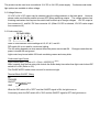
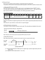
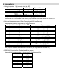
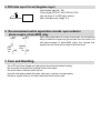
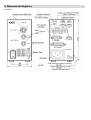
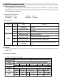
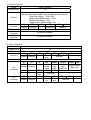
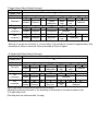
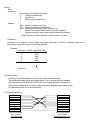
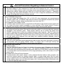
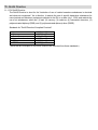
PDS-30 Instruction Guide
Digital Power Supply Unit for LED Lights
Safety Precautions
*Please read this instruction guide before using the product.
Thank you for purchasing PDS Power Supply for LED lights. Please read this Instruction
Guide carefully before using the product, and follow its instructions to ensure safe
operation. We also recommend keeping this Instruction Guide together with the product
for future reference.
Be sure to pay special attention to the information marked with " Danger," " Warning,"
or " Caution". The information is provided to prevent injury, electric shock and other
damages.
Indication symbols
This instruction guide contains following symbols which indicate precautions in order to
prevent injury or property damages. To ensure safe operations, please adhere to the
information provided in this instruction guide.
Danger
Indicates an imminently hazardous situation which, if not avoided, will result
in death or serious injury, as well as severe property damage.
Warning Indicates incorrect usage may result in serious injury or death.
Caution Indicates incorrect usage may result in injury or equipment damage.
Examples of indication symbols
Symbols indicate caution (also including danger and warning).
Specific examples are shown in the diagram (A diagram on the left indicates
electric shock warning).
Symbols indicate prohibition.
Specific examples are shown in the diagram. (A diagram on the left indicates
prohibition to disassemble)
Symbols indicate instruction for specific actions.
Specific examples are shown in the diagram. (A diagram on the left indicates
unplugging a power cord)
Danger
Please read this instruction guide carefully before using the product.
Following personnel should not handle this product.
1. A person who does not understand the contents of this instruction guide.
2. A person who does not have enough electrical equipment knowledge of at least
vocational school level.
3. A person who is under influence of illegal substances.
4. A person who is under influence of alcohol.
5. A person who uses a pace maker in the heart.
6. A person who is mentally disturbed.
7. A person who is a blind or a color blind.
Please do not attempt to perform any repairs.
This may result in electric shock or other hazardous situation.
Please contact CCS when repair is needed.
Please do not modify the products.
This may result in electric shock or other hazardous situation including fire.
If abnormal condition occurs such as fuming, product high temperature, smell, noise, or so
on, stop using the product immediately, and turn the power off.
Then contact CCS for inspection and repair.
If the product is under following condition, please stop the usage immediately, turn the
power off, and unplug;
- exposed to high impact by dropping
- damaged
- foreign materials or water entered in the product
Then contact CCS for inspection and repair.
Warning
Do not open the cover of the product.
Otherwise, electric shock may occur due to high voltage parts.
Please use the product within electricity specifications.
Otherwise it may cause fire and/or electric shock.
Please unplug the power cord when connecting or disconnecting the product and
peripherals.
Do not damage power cord or place any heavy objects on it. There are risks of damaging
the cord, which may result fire or electric shock.
Do not touch the terminals, plugs or switches with wet hands.
This may result in electric shock.
Always ground the power cord.
If not grounded, it may result in electric shock.
Do not look into the LED light directly. LED light is not as strong as semiconductor lasers.
However, avoid looking directly into any bright light or looking directly at the light for an
extended period while strobe. To do so may affect adversely to eyes.
Please use electricity within the product specification (PDS-30:AC100-240V, 50/60Hz).
Otherwise, it may cause fire or electric shock.
Please avoid following conditions to power cord;
Damaging, bending, twisting, pulling, heating, modifying, and putting heavy objects or
heavy weight on it. When unplugging, please pull plug itself, not power cable.
It may cause power code damage, and fire and electric shock)
Before moving products, disconnect power cords and other cables.
Damaging the cables may result in fire or electric shock.
Unplug the power cord while the product is not used for an extended period of time, will
ensure safety.
Please clean plug electrodes well more than once a year. Dust in the area may cause fire.
When cleaning the casing of the product, please turn the power off then unplug. Please
use dry cloth to clean the electrode.
If you touch this product simultaneously with any other electric products which have
different electrical potential from this product, this may result in electric shock. Therefore,
please ground from FG connector with 0.5 to 1.25 sq (AWG20 to AWG 16) wires. If those
equipments other than this product is not grounded but has electrical potential, It may be
safer to connect FG connectors of both products together.
Please ground PDS-30 with 3P grounding electrode power cord.
This product operates at a power supply voltage of 100 to 240V AC. The power cord
which is supplied with this product is for 100V. If the product is to be used at 200V or
above, please use an appropriate powers cord.
Do not use when dew is formed on the products.
If dew is formed, please dry the equipment thoroughly before usage.
When rubber feet are removed to mount this product in a system rack or case, the portion
of the M3 screws penetrating the case must be less than 2 mm long. If the insertion is
longer than 2mm, internal components may be short-circuited.
Please use this product on a stable surface with minimal vibration. A surface with rubber
pieces should be facing down.
Do not touch the power cords or connect peripheral devices during lightning.
Doing so may result in electric shock.
Caution
Turn the power off when connecting and disconnecting cables.
Otherwise it may result in fire and/or electric shock.
Please install product to locations in following conditions:
- In a flat and stable location with minimal vibration.
- Well-ventilated places with minimal dust.
- Place free from any water, oil, liquid, chemical, or steam.
- Place free from corrosive or combustible gas.
- Place away from water faucets, boilers, humidifiers, air conditioners, heaters, or stoves.
- Place that are not subject to sudden temperature changes.
- Place where products can be grounded.
Please do not place any object on the product.
Always provide a dedicated electric power source with stable voltage.
Sharing the electric power source with other power devices, such as inverters, motors, and so on, may
cause product malfunction.
Bundling the camera cable and power cord together may cause screen problems.
Set light intensity to maximum at high shutter speeds such as 1/4000 s. When light intensity is set to
maximum, we recommend intermittent use in external control or other modes.
Please use control input cable within specification of contact compliant cable. The longer the cable is,
easier the cable picks up noise. Shielded cable within 3m is recommended.
When using lights without cooling fan, please use intermittently in order to minimize temperature rise.
When the unit is used in any of the following conditions, please use the product well below rated
capacity and functions. Please also consider failsafe or better safety measures. You are encouraged
to contact CCS for further discussion.
- Usage under conditions or in an environment not described in this Instruction guide.
- Usage in nuclear power control, railways, aircraft, vehicles, combustion equipment, medical
applications, amusement devices, or safety devices.
- Usage in which there is a significant and foreseeable risk to life and property, particularly
applications demanding a high level of safety.
Contents
1. Features
2. Specifications
2-1 Specifications
2-2 Voltage Selector
2-3 Continuous Light
2-4 Strobe Light
2-5 Light Delay Time
2-6 External Control
2-7 RS-232C External Control
3. Operating Instructions
3-1 Connection
3-2 Power Supply Operation and Output Voltage Settings
3-3 Turning ON the Power Supply
3-4 Light Control
4. Connectors
4-1 Output connector: SM connector (mfd. by JST)
4-2 External interface connector: 5-pin D-sub plug with M2.6 mm Screws
4-3 RS-232C Connector
5. PDS Side Input Circuit
6. Recommended Control Signal Drive Circuit
7. Care and Handing
8. Dimensional diagrams
9. External Control using RS-232C
10. Glossary
11. RoHS Directive
11-1 EU RoHS Directive
11-2 China RoHS Directive
12. Warranty Information
1. Features
1-1 This product is a digital power supply for controlling CCS LED lights.
1-2 Selectable 12V DC and 24V DC output (cannot be used simultaneously).
1-3 Both continuous and strobe operation are available.
1-4 A PLC or a computer can control the power supply externally through RS-232C or parallel signal.
The DIP switches, on the front panel, enable to change lighting mode, an external control interface, and etc.
Mode Selector Switch
No.
ON
OFF
1
Strobe
Cont
Description
Light mode selector
Strobe: Strobe light synchronized to an external trigger input
Cont: Continuous light at a pulse width of 50 kHz
Remote control enabled/disabled
2
Remote
Manual
Remote: External control by RS-232C or bit-parallel signal.
Manual: Light control by panel switch settings
Remote control mode selector
RS-232C: Light control by commands sent via serial communications
3
RS-232C
Parallel
fixed at 9,600 bps
Parallel: Light control by a bit-parallel signal like an open collector signal
Strobe trigger polarity selector
Trig +: Applies the strobe trigger on the positive edge in the LOW-to-HI
4
Trig+
Trig transition.
Trig -: Applies the strobe trigger on the negative edge in the HI-to-LOW
transition.
ON/OFF polarity selector for continuous light
5
ON/OFF+ ON/OFF ON/OFF +: Lighting turns ON at HI.
ON/OFF -: Lighting turns ON at LOW.
Selector for fine rotary dial functions
6
Delay
Intensity
Delay: Switch for light delay settings
Intensity: Switch for fine light control
Factory settings: Only # 5 is ON and the others are OFF.
Turn the power off before changing mode switch settings.
2. Specifications
2-1 Specifications
Model
Input voltage
Input power
Frequency
Inrush current
Output power
PDS-30
100 to 240V AC
46W 110VA max. (at 100V AC)
50/60Hz ±10%
50A max. (at 100V AC)
0.75mA max.
By selecting output selector switch, either 12V or 24V lights may be connected.
Continuous Light: 12.0 ± 0.1V or 24.3 ±0.2V
Strobe Light: 18 ± 1V or 48 ± 1V
30W max.
Mode selection
DIP switches on the front panel
Control method
Continuous Light: Pulse duty control Frequency (50kHz)
Strobe Light: pulse width and pulse duty, AND type
Light control
Manual: Front panel rotary switch
Remote: RS-232C (9-pin D-Sub) or Bit-parallel signal (15-Pin D-Sub)
Resolution : Continuous Light (256levels) Strobe Light (128levels)
Terminal block: Strobe trigger, Constant light ON/OFF
15-pin D-Sub: Light control date input (8 bit), Writing signal, Trigger, ON/OFF input
non-insulated, Internally pulling up to +5 V power supply by
resistance, Light emitting output timing, Trigger delay output (Nte3)
Input level: 5V CMOS input, Pull up 4.7k, -0.5 to +5.5V max.
Pulse duty control, Strobe light pulse width, Strobe light pulse delay,
Trigger Output Delay (Nte3)
Data bit length: 8 bits, Stop bits: 1 bit, Parity check: None, Baud rate: 9,600 bps fixed.
SMP-02V-BC (mfd. by JST) 1:OUT+(+12V), 2:OUTSMP-03V-BC (mfd. by JST) 1:OUT+(+24V), 2:NC,
3:OUTSMP-04V-BC (mfd. by JST) 1:OUT+(+24V), 2:OUT+(+12V), 3:OUT-, 4:Fan GND
Between input and output connectors, between input connector and frame ground:
500V DC, 20 M min
Between output connector and frame ground: 50V DC, 10 M min
Between input and output connectors, between input connector and frame ground:
1,500V AC for one minute (10mA)
- Temperature: 0 to 40 °C, humidity: 20 to 85%RH (with no condensation)
- Altitude: 2,000 m max.
- Protective ground class I
- Pollution level: 2
- Installation category II (restricted to use in indoor environments)
Leakage current
Output voltage
Input-output control
RS-232C
Output connector
Insulation
Dielectric
Operating
environment
Storage
Temperature: -20 to 60°C, humidity: 20 to 85%RH (with no condensation)
environment
Applicable
LVD: EN61010-1
standards
EMC: EN61000-6-2, EN61000-6-4
Cooling method
Natural air cooling
(Nte2)
Dimensions
W62 x H110 x D170 mm
Weight
1.2 kg max.
Notes
1: The operating voltage range is 85 to 264V AC of the input voltage.
2: Product items such as the switch, latch and stand are not included.
3: Trigger delay output is externally synchronized signal (100µs fixed pulsation width)
The product can be used as a conventional 12-V DC or 24-V DC power supply. Continuous and strobe
light options are available in either voltage.
2-2 Voltage Selector
12-V DC or 24-V DC output may be selected using the voltage selector on the back panel. However,
please make sure that the product is turned OFF before switching outputs. The voltage selector has
a locking mechanism that requires the switch itself be lifted up to change voltages. 12V DC output is
from connector L1, and 24V DC from connector L2. (When 12V DC is selected, 12V DC is also output
from connector L2.)
2-3 Continuous Light
Refer to other sections for the settings at # 2, # 3, # 5, and # 6.
DIP switch # 4 is not used for continuous lighting.
The # 5 setting depends on what was set when the power was turned ON. Changes made after the
power is turned ON are ignored.
Light control may be set within 256 levels combining coarse and rotary dials.
Continuous Light Control
Light intensity date: (Coarse x 16 + Fine) x 100/255 [%] (Note1)
Note: however, that the fine rotary dial controls the strobe delay time rather than light control when DIP
switch # 6 is ON. (Refer to 2-5)
The PULSE WIDTH switch does not work for continuous light.
Terminal Block ON/OFF Wiring
NC
TRIGGER
ON/OFF
ON/OFF input
GND
When the DIP switch # 5 is "OFF" and the ON/OFF signal is ON, the light turns on.
Conversely, when the DIP switch # 5 is "ON" and the ON/OFF signal is OFF, the light turns on.
2-4 Strobe Light
Refer to other sections for the settings at # 2, # 3, # 4, and 6.
Dip switch # 5 is not used in strobe light.
Light pulse width: 20, 40, 60, 80,100,140,180, 260, 400, 500, and 1,000µs or 3, 5, 8, 10, and 33 ms
(±10 ms).
Overdrive is activated with 3 to 4 times the light output for light pulse width of 1,000µs or less.
Strobe Lighting Control
When the light pulse width more than 3 ms, output voltage becomes for normal continuous light and
overdrive becomes disabled. Strobe light can be adjusted by 128 levels combining the coarse and
fine rotary dials.
Light intensity date: (Coarse x 16 + Fine) x 100/255 [%] (Note1, Note2)
Note: however, that the fine rotary dial controls strobe delay time rather than light control when DIP
switch # 6 is ON. (Refer to 2-5)
Notes
1: This is a theoretical value. It varies by loads and extension cables, especially around 0% as well
as 100% setting.
2: Strobe light resolution becomes half to 128 levels. (128 levels: 0,1,3,5,7,…,255)
Trigger Input Wiring
NC
TRIGGER
ON/OFF
GND
Trigger input
When DIP switch # 4 is OFF and trigger input signal is ON, strobe light turns ON.
Conversely, when DIP switch # 4 is ON and trigger input signal OFF, strobe light turns ON.
2-5 Light Delay Time
When DIP switch # 6 is ON, the delay time from the trigger input until the light turns ON, may be set by
fine rotary dial. In this case, only the coarse rotary dial is used for light control (error ±10µs).
Fine
0
1
2
3
4
5
6
7
Delay [µs]
10
30
60
80
100
150
200
250
Fine
8
9
A
B
C
D
E
F
Delay [µs]
300
500
750
1000
2000
4000
8000
10000
2-6 External Control
External control mode may be selected by turning DIP switch # 2 (remote) ON.
The position of DIP switch # 3 determines whether bit-parallel or RS-232C be used for external control.
(1) Bit-parallel (DIP Switch # 3: OFF)
The15-pin D-sub connector on the back panel may be used for light control and ON/OFF control.
The rotary dials on the front panel are enabled when pin #9 (INT/EXT) is OFF. When pin #9 is ON,
light control and ON/OFF control are based on the following input status conditions.
Control Bit Configuration
Bit
B1
Construction (LSB)
B2
B3
B4
B5
B6
B7
Light intensity data (0 to FF)
B8
B9
(MSB) INT/ENT
B10
B11
B12
/WR
OFF/
ON
TRIG
(2) Signal Logic
Data and control bits are negative logic bits (active LOW: maximum light intensity date when all bits are
LOW).
Use a driver IC, open collector, or other device to output the signal.
(3) External/manual control selector
This selector is used to switch to external control mode. (The rotary dials are disabled in this mode.)
External Control Mode Selection - B9 (INT/EXT)
Manual
NPN open collector ON
External
Note: External control mode cannot be selected if DIP switch # 2 is OFF.
(4) Data Entry Sequence
Note: Data can be written in external control mode, but not in manual control mode.
B1 to B8
(8 bits)
Write B10
(/WR)
Thd
Tst
Write light intensity data
Tst ≥ 100 µ s
Tpw ≥ 1 ms
Tpw
Thd ≥ 100 µ s
NPN open collector ON
(i) The light intensity data (B1 to B8) outputs in negative logic (maximum light intensity date with
all bits LOW).
(ii) It outputs the write bit (data written in 1 ms max.).
(5) Other I/O and Voltage Levels
The same ON/OFF signal (B11) and trigger signal (B12) that are input from the terminal block signals
can be input from the D-sub connector. With strobe light, the delay trigger signal (B13) that is used to
synchronize the external device set via RS-232C and the pulse light signal (B14) that is used to
confirm light are output at active LOW (5 V-CMOS level).
The pulse width of the delay trigger signal is always 100µs regardless of the pulse width of the trigger
input. The bit-parallel control signal is a 5V-CMOS level input (LOW: 1.35V max.; HI: 3.15V min.)
2-7 RS-232C External Control
Refer to 9.RS-232C External Control for details on external control via RS-232C.
3. Operating Instructions
3-1 Connection
Turn the power off.
Connect the LED light cable to the output connector on the power supply back panel.
Ground the FG terminal of the 10-W model with 0.5 to 1.25 sq wire (AWG20 to AWG16).
Connect power cord to wall socket.
When using external control, the control signal should be connected to the back panel connector.
3-2 Operation and Output Voltage Settings
It sets the mode selector DIP switch on the front panel and the voltage selector switch on the back
panel.
3-3 Turn the power on.
Turn ON the Power switch.
3-4 Light Control
In manual mode, the light intensity can be controlled with the coarse and fine rotary dials.
The pulse width can be set for strobe light in this mode from the pulse width setting switch.
Note: Press the test button on the front panel to manually check the strobe when strobe light is
selected.
4. Connectors
4-1 Output connector: SM connector (mfd. by JST)
Pin No.
12 V output
24 V output
Output with fan (Note)
1
OUT+(+12V)
OUT+(+24V)
OUT+(+24V)
2
OUTNC
OUT+(+12V)
3
OUTOUT4
Fan GND
Connector
SMP-02V-BC
SMP-03V-BC
SMP-04V-BC
Note) With fan: L1/L2 (FAN) output connector for lighting with a fan
Output with fan is not available when strobe (ON) is selected with mode selector DIP switch # 1.
4-2 External interface connector: (15-pin D-sub plug with M2.6mm Screws)
Use a shielded cable no longer than 3m for the control line.
Pin No. Color of the Optional Cable (Note)
Signal
1
Black
Light intensity date B1[LSB]
2
White
Light intensity date B2
3
Red
Light intensity date B3
4
Green
Light intensity date B4
5
Yellow
Light intensity date B5
6
Brown
Light intensity date B6
7
Blue
Light intensity date B7
8
Purple
Light intensity date [MSB]
9
Gray
External control (INIT/EXT) B9
10
Pink
Light intensity data write (/WR) B10
11
White/Black
ON/OFF control (ON/OFF)
12
Red/Black
Trigger input (/TRIG) B12
13
Green/Black
Trigger delay output (TDLY) B13
14
Yellow/Black
Pulse output (FLSH) B14
15
Brown/Black
Signal GND
Note) Optional cable for external control: EXCB2-B3 (3m long cable with one end cut.)
4-3 RS-232C Connector 9-pin D-sub plug with inch screws
Use a shielded crossover cable no longer than 3 m for the control line.
Pin No.
Signal
1
NC
2
RXD
3
TXD
4
DTR
5
GND
6
DSR
7
RTS
8
CTS
9
NC
5. PDS Side Input Circuit (Negative logic)
+5 V
4.7k
Internal circuit
Light intensity data: B1 – B8
Control signal: INT/EXT, WR, OFF/ON, TRIG
Use with driver IC or NPN open collector.
(Max. allowable input voltage: 6 V)
6. Recommended control signal drive circuits: open collector
photo-coupler, photo-MOS relay
Signal
LS05
LS06
etc
Signal
Switch
Relay
etc
When using the product in a noisy environment, we recommend
that you isolate the signal and ground lines from the control unit
with photo-couplers or photo-MOS relays. Any element that
supplies around 10mA can be used to drive the circuit.
7. Care and Handling
- Turn OFF the Power Supply and unplug from the wall socket before handing.
- Do not scratch the product by handling it with a hard object.
- Do not let water or cleanser enter the unit.
- Use soft cloth lightly soaked with water, mild soap, or alcohol, and wipe gently.
- Kerosene, organic solvent, and other chemicals should not be used.
8. Dimensional diagrams
8-1 PDS-30
Light
9. RS-232C External Control
9-1 RS-232C External Control (9-pin D-sub)
Turning DIP switch # 2 and # 3 ON enables external control via RS-232C. By sending external
commands that conform to the transmission specifications, will enable to control the power supply with
a PC or other external devices.
9-2 Transmission specifications
Data bit length: 8 bits
Parity check:
None
Stop bits: 1 bit
Baud rate: 9,600 bps
9-3 Command list
The following commands can be used.
Header
Type
Name
code
Version confirmation
V
command
Transmission
Reset command
R
Query command
Trigger output delay
setting command
Strobe light width
setting command
Strobe delay
setting command
Q
T
S
Setting
D
Pulse width setting
command
F
Function
It returns the version number of the loaded device
software.
It resets the transmission sequence that is currently
executing.
It returns the status of all settings.
It sets the delay time for external output of the timing
signal for strobe light.
It sets the pulse width for strobe light.
It sets the delay time for strobe light.
It sets the duty ratio for pulsed light width.
Light control for both Continuous and Strobe light
mode.
9-4 Channels
It can be set from 00 to 15 (16 channels max.). A channel number available on a single-channel power
supply is 00.
9-5 Command Description
V: Version Confirmation Command
Name
Version confirmation command
Header code
V
Function
It returns the version number of the loaded device software.
@
99
V
FF
CR
LF
Header
Channel
Checksum
Delimiter
Command
Response
OK
command
NG
command
@
99
Header
Channel
@
99
Header
Channel
FF
Version No.
N
Checksum
9
FF
Error No.
Checksum
CR
LF
Delimiter
CR
LF
Delimiter
R: Reset Command
Name
Reset command
Header code
Function
Command
R
It resets the transmission sequence that is being executed,
clears all transmission buffers, and re-initializes transmissions.
Pulse Duty Setting: 100% (255)
Strobe Pulse Width Setting: 20µs
Strobe Delay Setting: 0µs
Trigger Output Delay Setting: 0µs
@
99
R
FF
CR
LF
Header
Channel
Checksum
Delimiter
Response
OK
command
NG
command
No return command
No return command
Q: Query Command
Name
Header code
Function
@
Command
99
Header Channel
Query command
Q
It returns the status of all settings.
Q
FF
CR
LF
Check
Delimiter
sum
Response
@
OK
command
NG
command
99
A
Header Channel
@
99
Header Channel
FF
Check
sum
N
999
Light
pulse
width
CR
99999
Strobe
light
width
LF
99999
Strobe
light
delay time
99999
Trigger output
delay time
Delimiter
9
Error
No.
FF
Check
sum
CR
LF
Delimiter
T: Trigger Output Delay Setting Command
Name
Trigger output delay setting command
Header code
T
Function
It sets the delay time of external output timing signal for strobe light.
@
99
T
99999
R/W
FF
CR
LF
Output
Write
Checks
Delimiter
Header Channel
delay time
flag
um
Command
Response
OK
command
NG
command
@
99
Header
Channel
@
99
Header
Channel
O
FF
CR
Checksum
N
9
Error No.
LF
Delimiter
FF
Checks
um
CR
LF
Delimiter
The output delay time may be set from 0µs to 10,000µs.
Although it can be set increment of 1µs as setting, it will actually be rounded in approximately 20µs
increments at 300µs or lower and 100µs increments at 320µs or higher.
D: Strobe Light Delay Setting Command
Name
Strobe light delay setting command
Header code
D
Function
@
Command
Header
It sets the delay time for strobe light.
99
D
99999
R/W
FF
Strobe light
Write
Check
Channel
delay time
flag
sum
CR
LF
Delimiter
Response
OK
command
NG
command
@
99
Header
Channel
@
99
Header
Channel
O
FF
Checksum
N
9
Error No.
CR
LF
Delimiter
FF
Checks
um
CR
LF
Delimiter
Strobe light delay time may be set from 0µs to 10,000µs.
Although it can be set increment of 1µs as setting, it will actually be rounded as shown at the
“2-5 Light Delay Time”.
(The delay time can not be set with 1µs step)
S: Strobe Light Width Setting Command
Name
Strobe Light Width Setting command
Header
S
code
Function
It sets the pulse width for strobe light.
@
99
S
99999
R/W
FF
Command
Strobe
Header Channel
Write flag Checksum
light width
Response
@
99
O
FF
CR
LF
OK
Command Header Channel
Checksum
Delimiter
NG
Command
@
99
N
Header Channel
9
FF
Error No.
Checksum
CR
LF
Delimiter
CR
LF
Delimiter
Strobe light width may be set from 20µs to 33,000 µs.
Although it can be set increment of 1µs, it will actually be rounded as shown at
“2-4 Strobe Light”. (Strobe light width can not be set with 1µs increment)
F: Light Pulse Width Setting Command
Name
Light Pulse Width Setting Command
Header
F
code
Function
It sets the duty ratio for pulsed light width.
@
99
F
999
R/W
FF
Command
Light pulse
Check
Header Channel
Write flag
width
sum
Response
@
99
O
FF
CR
LF
OK
command Header Channel
Checksum
Delimiter
99
N
9
LF
Delimiter
FF
CR
LF
Check
Header Channel
Error No.
Delimiter
sum
Light intensity date 0 to 255; the pulse duty ratio varies within 0 to 100% expressed in incremental
value of100% divided by 256.
In case of Strobe Mode, the value halves to 128 increments. (0,1,3,5,7,….,255)
NG
command
@
CR
(Notes)
Error
Numbers
Error numbers are defined as follows:
1:
Faulty command error
2:
Check error
3:
Setting out-of-range error
Notation
999: Specify numbers in decimal.
FF: Specify numbers in hexadecimal.
R/W: Always set write data to flash memory. (Note)
Select R for write prohibited and W for write enabled.
Settings cannot be saved when write prohibited is selected.
Note) Endurance / Data retention: 1 million cycles / 10 years
Checksum
Checksum is a character string, which has been converted to ASCII, containing total sum of
lower-order 1-byte values up to a checksum position.
Example
Character
@
L
9
9
9
Total
ASCII code (HEX code)
40H
4CH
39H
39H
39H
137H
Checksum
37
9-6 Serial Cables
Use 9-pin D-Sub serial cable in order to connect to external devices.
The serial cable should be a cross cable that is 15 m or shorter and fully shielded.
(We recommend: C06-09F-09F-CROSS-910 (3 m) [made by Misumi Group Inc.])
Noise will be introduced with a longer cable, resulting in possible transmission errors.
(A cable shorter than 3m is recommended)
9-7 Cable Connections
1
2
3
4
5
6
7
8
Frame
9-pin D-sub socket
(inch screws)
PC and PLC side
1
2
3
4
5
6
7
8
Frame
9-pin D-sub socket
(inch screws)
PDS power supply side
General Precautions Regarding to External Control
1. Bit Parallel Input Voltage
The input voltage is 1.35V maximum for “LOW” and 3.15V minimum for “HI”. Faulty operation
may occur if a open collector output is two-stage, and a surge absorbing diode connected in series.
Because the residual voltage goes up as high as 1.5V when the power is turned on. Meanwhile,
the voltage may drop (pull-up resistance x IL) and “HI” can no longer be maintained if the leakage
current (IL) is high when the open collector turns off.
2. Controlling Output Units
(2-1) TTL/CMOS Output Units
The load voltage often ranges from 10.2 to 26.4V DC when sequencers use general-purpose
transistor output units. TTL/CMOS output units are ideal for this application because they operate
on +5 V and their residual voltage is guaranteed never more than 0.4 V.
(2-2) Separate Power Supply Control
A multi-bit output unit that is used to control both the PD power supply and the power system drive
unit makes the power system susceptible to noise because of the wiring involved. Provide a
separate power supply control unit to isolate the power supply from the power system.
3. Entry Sequence
The setup and hold time takes 100µs and the write pulse width is 1ms for the data entry sequence
described in this instruction guide. These figures, however, do not include the control circuit
ON/OFF response time or delay time variations between output channels. The PLC device and
photo coupler output for image processing also have relatively slow ON and OFF response times of
0.5ms and 1ms, respectively. Therefore, all the factors such as power supply setup time, hold time
with the output circuit response time, and delay time variations between channels, must be
considered in data entry.
4. Writing Light Intensity Data
There are some applications where light intensity data is written once when the power is turned on
and thereafter offer only lighting ON/OFF control. It is always safer to write light intensity data
every time even in those applications if the processing time allows it.
5. Wiring and Safety Measures
(5-1) Ground Wire
Wire the COM (GND) from the Output Unit directly to the power supply. Otherwise noise becomes
a factor and faulty operation is likely to occur. This happens because the GND level is raised by
COM current from somewhere other than the power supply if the COM (GND) is relayed by wiring it
to a terminal block and then branched it off for image processing, motor valve control, or the PD
power supply.
(5-2) Measures to Prevent Faulty Operation
If synchronization with motors, valves or other peripheral devices leads to faulty operation, then
move the external control line, lighting extension cable, or power supply away from the motor,
valve, or respective drive line causing the problem. Other possibilities for improving noise protection
include adding a ferrite core near the power supply unit or using shielded cable, twisted pair cable,
or cable with high EMI noise immunity.
When the luminosity of light fluctuate due to excess amount of noise, please contact CCS.
10. Glossary
1. Parallel
Method which is used to send multiple data simultaneously, and its interface.
2. Serial
Method which is used to send data one bit per cable at the time. Antonym of Parallel.
3. RC-232C
Serial interface standard which is used to majority of PC and peripheral equipment.
4. D-Sub
One of the types of connector which is used for electrical communication. It has flat trapezoidal shape
topographical profile, and two rows of pins. There are few kinds of them such as 9-pins, 15 pins, 25
pins, 50pins, etc.
5. AWG (American Wire Gauge)
Standard of conductive wire which diameter is divided by certain ratio, and numbered.
i.e.) AWG16: 1.290mm AWG18: 1.020mm AWG20: 0.812mm
6. FG (Frame Ground) connector
Connector which is used to place casing.
7. Parity check
Error detecting method which adds extra 1 bit to data digit by computer and makes a situation when the
number of 1’s becomes either odd or even numbers.
8. baud rate
Unit of communication modulating speed
9. Checksum
algorithm used to detect error
10. Delimiter
a character that marks the beginning or end of a unit of data
11. ASCII Code
American standard code for information exchange legislated by ANSI
11. RoHS Directive
11-1 EU RoHS Directive
The RoHS Directive is short for the "restriction of use of certain hazardous substances in electrical
and electronic equipment." As a directive, it restricts the use of specific hazardous substances for
new electrical and electronic equipment marketed in the EU on or after July 1, 2006, and restricts the
use of six substances, which are (1) lead, (2) mercury, (3) cadmium, (4) hexavalent chromium, (5)
polybrominated biphenyl (PBB), and (6) polybrominated diphenyl ether (PBDE).
Standards for "RoHS Directive-Compliant Products"
Lead
1000ppm Min
Mercury
1000ppm Min
Cadmium
100ppm Min
Hexavalent chromium
1000ppm Min
PBB
1000ppm Min
PBDE
1000ppm Min
(Items that are exempted in the RoHS Directive are excluded from these standards.)
11-2 China RoHS Directive
China RoHS Directive is formally known as "Management Methods for Controlling Pollution by
Electronic Information Products", which was implemented on March 1, 2007 in China. Same as EU
RoHS Directive, this regulation restricts the usage of six substances such as lead, mercury, cadmium,
hexavalent chromium, polybrominated biphenyl (PBB), and polybrominated diphenyl ether (PBDE).
This regulation requires electronic information products which are manufactured or imported, and sold
in China, to clearly disclose contents of the 6 restricted substances listed below.
Name and amount of toxic and hazardous substances or elements, which products contain
Usage
Deadline for
Environmental
Protection
Product name
Lead
(Pb)
Toxic or Hazardous Substances and Elements
Hexavalent
Mercury Cadmium
chromium
PBB
(Hg)
(Cd)
(Cr(VI))
PBDE
Power supply
for LED Lights
:Indicates that this toxic or hazardous substances contained in all the homogeneous materials for this
part, according to SJ/T11363-2006 is within the limit requirement.
:Indicates that this toxic or hazardous substance contained in all the homogeneous materials for this
part, according to SJ/T11363-2006, is over the limit requirement.
( )Lead and cadmium are excluded in EU RoHS.
Usage deadline for environmental protection
The number used in this logo is based on “Management Methods for Controlling Pollution by Electronic
Information Products” and related regulations from People’s Republic of China. It shows the product
usage duration in years for environmental protection. After finishing a product usage, the product need
to be re-used or discard appropriately following local law and regulations, complying with safety and
usage caution.
12. Warranty Information
Warranty period: Two years (one year for radiant quantity), starting from CCS Inc. shipping date.
CCS Inc. will repair or replace the product free of charge if it should fail to function or if the radiant quantity
of the product should drop to 50% or less of its initial radiant quantity within the specified warranty period.
If either of these conditions occurs, please take the product to your CCS sales representative.
Warranty Terms
1. CCS Inc. will repair or replace the product free of charge if it should fail to function under normal use in
accordance with the Instruction Guide and other written cautions during the indicated warranty period
of two years
2. CCS Inc. will repair or replace the product free of charge if its radiant quantity should drop to 50% or
less of its initial radiant quantity under normal use in accordance with the Instruction Guide and other
written cautions during the indicated warranty period of one year.
3. CCS Inc. will charge a repair fee under the following conditions :
1) If the product has been subjected to misuse, unauthorized repairs, or modification from its original
design.
2) If the product has been damaged from impacts due to inappropriate handling
3) If damage to the product results from external causes including accidents, fire, pollution, riots,
communication failures, earthquakes, thunderstorms, wind and flood damage, or any other act of
providence, or from any extraordinary conditions such as electrical surges, water leakage,
condensation, or the use of chemicals
4) If the damage results from connection to any power supply or to any equipment which CCS Inc.
does not manufacture or does not specify for use
This warranty information provides the scope of CCS's product warranty within the specified period, and
does not indicate or imply any further guarantee beyond the warranty terms.
Contact CCS for inquiries or information on repairs to the product after the expiration of the warranty.
Head Office
Shimodachiuri-agaru, Karasuma-dori
Kamigyo-ku, Kyoto 602-8011 Japan
Phone: +81-75-415-8284, Fax: +81-75-415-8278
KZ01074-T001-000
http://www.ccs-grp.com
[email protected]
Copyright(c) 2007 CCS Inc. All Rights Reserved. C