1
CJ-500
USER'S MANUAL
Thank you for purchasing the CJ-500.
•
To ensure correct and safe usage with a full understanding of this
product's performance, please be sure to read through this manual
completely and store it in a safe location.
•
Unauthorized copying or transferral, in whole or in part, of this manual
is prohibited.
•
The contents of this operation manual and the specifications of this
product are subject to change without notice.
•
The operation manual and the product have been prepared and tested as
much as possible. If you find any misprint or error, please inform us.
•
Roland DG Corp. assumes no responsibility for any direct or indirect
loss or damage which may occur through use of this product, regardless
of any failure to perform on the part of this product.
For the USA
FEDERAL COMMUNICATIONS COMMISSION
RADIO FREQUENCY INTERFERENCE
STATEMENT
This equipment has been tested and found to comply with the
limits for a Class A digital device, pursuant to Part 15 of the
FCC Rules.
These limits are designed to provide reasonable protection
against harmful interference when the equipment is operated
in a commercial environment.
This equipment generates, uses, and can radiate radio
frequency energy and, if not installed and used in accordance
with the instruction manual, may cause harmful interference
to radio communications.
Operation of this equipment in a residential area is likely to
cause harmful interference in which case the user will be
required to correct the interference at his own expense.
NOTICE
Grounding Instructions
Do not modify the plug provided - if it will not fit the outlet,
have the proper outlet installed by a qualified electrician.
Check with qualified electrician or service personnel if the
grounding instructions are not completely understood, or if in
doubt as to whether the tool is properly grounded.
Use only 3-wire extension cords that have 3-prong
grounding plugs and 3-pole receptacles that accept the tool’s
plug.
Repair or replace damaged or worn out cord immediately.
Operating Instructions
KEEP WORK AREA CLEAN. Cluttered areas and benches
invite accidents.
Unauthorized changes or modification to this system can void
the users authority to operate this equipment.
DON’T USE IN DANGEROUS ENVIRONMENT. Don’t
use power tools in damp or wet locations, or expose them to
rain. Keep work area well lighted.
DISCONNECT TOOLS before servicing; when changing
accessories, such as blades, bits, cutters, etc.
The I/O cables between this equipment and the computing
device must be shielded.
REDUCE THE RISK OF UNINTENTIONAL STARTING.
Make sure the switch is in off position before plugging in.
USE RECOMMENDED ACCESSORIES. Consult the
owner’s manual for recommended accessories. The use of
improper accessories may cause risk of injury.
NEVER LEAVE TOOL RUNNING UNATTENDED.
TURN POWER OFF. Don’t leave tool until it comes to a
complete stop.
For Canada
CLASS A
NOTICE
This Class A digital apparatus meets all requirements of the
Canadian Interference-Causing Equipment Regulations.
CLASSE A
AVIS
Cet appareil numérique de la classe A respecte toutes les
exigences du Règlement sur le matériel brouilleur du
Canada.
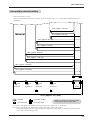
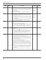
Table of Contents
To Ensure Safe Use ....................................... 2
About the Labels Affixed to the Unit ...... 4
Pour utiliser en toute sécurité ......... 6
À propos des étiquettes collées sur l'appareil .... 9
Unpacking the CAMMJET..................................... 11
1
Checking Accessories .......................................... 11
2
Setting Up and Connection .................................. 12
3
Attaching the Drain Bottle .................................... 14
4
Installing Ink Cartridges ........................................ 16
5
Power up ................................................................. 18
Part Names ................................................................. 19
Front View ..................................................................... 19
Rear View ..................................................................... 20
Inside the Front Cover ................................................ 20
Operation Panel ........................................................... 21
Five modes ................................................................. 22
Setup for Printing ................................................. 23
1 Loading the Material ............................................... 23
2 Test Printing ............................................................. 27
3 Setting the Printing Mode and Printing Direction ....... 28
Setup for Cutting ................................................... 29
1 Loading the Material ............................................... 29
2 Installing a Blade ..................................................... 33
3 Test Cutting .............................................................. 34
Setup for Printing and Cutting .................. 36
Maintenance .............................................................. 42
Replacing the Ink Cartridges ..................................... 42
Check how much ink remains .................................... 44
Cleaning the Printing Heads ...................................... 44
Changing the Type of Ink ........................................... 46
Replacing the Cutter Blade ........................................ 47
How to Replace the Separating Knife ...................... 48
When the Product Needs Cleaning .......................... 49
When Not in Use for a Prolonged Period... ............. 50
When Moving the Unit... ............................................. 51
User's Reference ................................................... 53
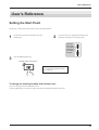
Setting the start point....................................................... 53
Adjusting the Printing and Cutting Positions ........... 54
Remove the Printed Material,
then Reload the Material and Perform Cutting ................. 56
Making Corrections for Printing ................................. 59
Aligning the Printing Length and Cutting Length ............ 61
Performing Overprinting ............................................. 63
Setting the Page Margins ........................................... 64
About the Prefeed ([PREFEED]) Function .............. 65
To Perform Long Printing/Cutting ............................. 66
Adjusting the Height of the Printing Head ................ 67
Materials ........................................................................ 68
About Blade Life .......................................................... 70
About the Printing/Cutting Area ................................. 71
Description of Keys ............................................ 72
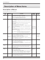
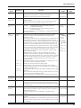
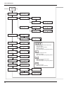
Description of Menu Items ........................... 74
Description of Menu..................................................... 74
Display Menu Flowchart ............................................. 77
Downloading Printing/Cutting Data .......... 37
What to Do If... ......................................................... 81
Removing the Material ..................................... 39
Error Messages ...................................................... 86
Remove the Material from the machine ................... 39
Cut the material from the roll ..................................... 39
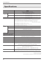
Specifications .......................................................... 88
When Operations Are Finished ................ 41
Windows® is a registered trademark or trademark of Microsoft® Corporation in the United States and/or other countries.
IBM is a registered trademark of International Business Machines Corporation.
Macintosh is a registered trademark or trademark of Apple Computer, Inc. in the USA and other countries.
Other company names and product names are trademarks or registered trademarks of their respective holders.
COLORCHOICE® is a registered in the U.S. Patent Office.
Copyright © 1999 ROLAND DG CORPORATION
1
To Ensure Safe Use
About
and
Notices
Used for instructions intended to alert the user to the risk of death or severe
injury should the unit be used improperly.
Used for instructions intended to alert the user to the risk of injury or material
damage should the unit be used improperly.
* Material damage refers to damage or other adverse effects caused with
respect to the home and all its furnishings, as well to domestic animals or
pets.
About the Symbols
The
symbol alerts the user to important instructions or warnings. The specific meaning of
the symbol is determined by the design contained within the triangle. The symbol at left means
"danger of electrocution."
The
symbol alerts the user to items that must never be carried out (are forbidden). The
specific thing that must not be done is indicated by the design contained within the circle. The
symbol at left means the unit must never be disassembled.
The
symbol alerts the user to things that must be carried out. The specific thing that must
be done is indicated by the design contained within the circle. The symbol at left means the
power-cord plug must be unplugged from the outlet.
Do not disassemble, repair, or
modify.
Use only with a power supply of the
same rating as indicated on the unit.
Doing so may lead to fire or abnormal
operation resulting in injury.
Use with any other power supply may lead
to fire or electrocution.
Ground the unit with the ground
wire.
Do not use while in an abnormal
state (i.e., emitting smoke, burning
odor, unusual noise, or the like).
Failure to do so may result in risk of
electrical shock in the even of a mechanical
problem.
2
Doing so may result in fire or electrical
shock.
Immediately switch off first the sub power,
then the main power, unplug the power cord
from the electrical outlet, and contact your
authorized Roland DG Corp. dealer or
service center.
Do not use with a damaged power
cord or plug, or with a loose
electrical outlet.
When not in use for extended
periods, unplug the power cord from
the electrical outlet.
Use with any other
power supply may
lead to fire or
electrocution.
Failure to do so may
result in danger of
shock, electrocution,
or fire due to
deterioration of the
electrical insulation.
Do not injure or modify the electrical
power cord, nor subject it to
excessive bends, twists, pulls,
binding, or pinching, nor place any
object of weight on it.
When unplugging the electrical
power cord from the power outlet,
grasp the plug, not the cord.
Unplugging by pulling the cord may damage
it, leading to fire or electrocution.
Doing so may
damage the
electrical power
cord, leading to
electrocution or
fire.
Do not attempt to unplug the power
cord with wet hands.
Do not allow liquids, metal objects
or flammables inside the machine.
Doing so may
result in electrical
shock.
Such materials
can cause fire.
Unpacking, installation, and moving
must be carried out by two or more
persons.
Use the joining screws to secure the
unit to the stand.
Failure to do so
may result in
falling of the
unit, leading to
injury.
Install in a level and stable location.
Otherwise the unit may tip over and cause
injury.
Failure to do so
may result in
falling of the unit,
leading to injury.
Use care to avoid pinching the
fingers when placing the unit on the
stand.
Doing so may
result in injury.
Roll material must be placed at a
predetermined shaft position.
Release the caster locks for the
stand before attempting to move.
Failure to do so may
result in falling of the
roll, leading to injury.
Otherwise the unit may tip over and cause
injury.
Do not touch the tip of the
separating knife with your fingers.
Make sure the power to the unit is
off before attempting to replace the
separating knife.
Doing so may result in injury.
Doing so may result in injury.
3
Do not place hands within the space
to the front of the unit while in
operation.
If ink contacts the eyes, flush
immediately with water.
Doing so may result in injury.
Store ink cartridges out of the reach
of children.
About the Labels Affixed to the Unit
These labels are affixed to the body of this product.
The following figure describes the location and
content of these messages.
Ink cartridge
Do not dismantle the cartridge.
Keep out of reach of children.
Do not store the cartridge in high or freezing temperatures.
4
Do not place hands
within the space to
the front of the unit
while in operation.
Model name
Rating label
Proper voltage required.
In addition to the
NOTICE
and
symbols, the symbols shown below are also used.
: Indicates information to prevent machine breakdown or malfunction and ensure correct use.
: Indicates a handy tip or advice regarding use.
5
Pour utiliser en toute sécurité
Avis sur les avertissements
Utilisé pour avertir l'utilisateur d'un risque de décès ou de blessure grave en
cas de mauvaise utilisation de l'appareil.
Utilisé pour avertir l'utilisateur d'un risque de blessure ou de dommage
matériel en cas de mauvaise utilisation de l'appareil.
* Par dommage matériel, il est entendu dommage ou tout autre effet
indésirable sur la maison, tous les meubles et même les animaux
domestiques.
À propos des symboles
Le symbole
attire l'attention de l'utilisateur sur les instructions importantes ou les
avertissements. Le sens précis du symbole est déterminé par le dessin à l'intérieur du triangle.
Le symbole à gauche signifie "danger d'électrocution".
Le symbole
avertit l'utilisateur de ce qu'il ne doit pas faire, ce qui est interdit. La chose
spécifique à ne pas faire est indiquée par le dessin à l'intérieur du cercle. Le symbole à
gauche signifie que l'appareil ne doit jamais être démonté.
Le symbole
prévient l'utilisateur sur ce qu'il doit faire. La chose spécifique à faire est
indiquée par le dessin à l'intérieur du cercle. Le symbole à gauche signifie que le fil électrique
doit être débranché de la prise.
Ne pas démonter, réparer ou
modifier.
Le non-respect de cette consigne pourrait
causer un incendie ou provoquer des
opérations anormales entraînant des
blessures.
Mettre l'appareil à la masse avec une
prise de terre.
Le non-respect de cette consigne pourrait
entraîner des décharges électriques en
cas de problème mécanique.
6
Utiliser seulement avec une
alimentation de mêmes
caractéristiques électriques que
celles indiquées sur l'appareil.
Une négligence à ce niveau pourrait
provoquer un incendie ou une
électrocution.
Ne pas utiliser si l'appareil est dans
un état anormal (c'est-à-dire s'il y a
émission de fumée, odeur de brûlé,
bruit inhabituel etc.).
Le non-respect de cette consigne pourrait
provoquer un incendie ou des décharges
électriques.
Couper immédiatement l'alimentation
secondaire et ensuite l'alimentation
principale. Débranchez le fil électrique et
contacter votre revendeur ou votre centre
de service de la société Roland DG
autorisé.
Ne pas utiliser avec une fiche ou un
fil électrique endommagé ou avec
une prise mal fixée.
Débrancher le fil lorsque l'appareil
reste inutilisé pendant une longue
période.
Une négligence à
ce niveau pourrait
provoquer un
incendie ou une
électrocution.
Une négligence à ce niveau pourrait
provoquer des décharges électriques,
une électrocution ou
un incendie dû à une
détérioration de
l'isolation électrique.
Ne pas endommager ou modifier le
fil électrique. Ne pas le plier, le
tordre, l'étirer, l'attacher ou le serrer
de façon excessive. Ne pas mettre
d'objet ou de poids dessus.
Saisir la fiche et non le fil électrique
lorsque vous débranchez.
Débrancher en tirant sur le fil pourrait
l'endommager et risquer de provoquer un
incendie ou une électrocution.
Une négligence à
ce niveau pourrait
endommager le fil
électrique ce qui
risquerait de
provoquer une
électrocution ou un
incendie.
Ne pas essayer de débrancher le fil
avec des mains mouillées.
Une négligence à
ce niveau pourrait
provoquer des
décharges
électriques.
Le déballage, l'installation et le
déplacement de l'appareil doivent
être effectués par deux personnes
ou plus.
Le non-respect de cette consigne pourrait
causer des défauts dans l'appareil
entraînant des blessures.
Installer dans un endroit stable et de
niveau.
Sinon l'appareil pourrait se renverser et
provoquer des blessures.
Ne pas introduire de liquide, d'objet
métallique ou inflammable dans
l'appareil.
Ce genre de
matériel peut
provoquer un
incendie.
Utiliser les vis fournies pour bien
fixer l'appareil sur le support.
Le non-respect de
cette consigne
pourrait causer des
défauts dans
l'appareil entraînant
des blessures.
Manipuler avec précaution pour
éviter de se coincer les doigts lors
de l'installation de l'appareil sur le
support.
Une négligence à
ce niveau pourrait
provoquer des
blessures.
7
Le rouleau doit être placé quand la
barre est en position adéquate.
Une négligence à ce
niveau pourrait
provoquer la chute du
rouleau et causer des
blessures.
Ne pas toucher à l’extrémité de la
lame avec vos doigts.
Vous risqueriez de vous blesser en y
touchant.
Ne pas mettre les mains dans
l'espace du devant quand l'appareil
est en marche.
Débloquer le mécanisme d'arrêt des
roulettes du support avant de le
déplacer.
Sinon l'appareil pourrait se renverser et
provoquer des blessures.
S'assurer que l'appareil est hors
tension avant d'essayer de
remplacer la lame séparatrice.
Une négligence à ce niveau pourrait
provoquer des blessures.
Si de l'encre entre en contact avec
les yeux, rincer immédiatement à
l'eau.
Une négligence à ce niveau pourrait
provoquer des blessures.
Ranger les cartouches d'encre hors
de portée des enfants.
8
À propos des étiquettes collées sur l'appareil
Ces étiquettes sont collées à l'extérieur de l'appareil.
Les dessins suivants indiquent l'endroit et le contenu des messages.
Ne pas mettre les
mains dans l'espace
devant l'élément
quand celui-ci est
en marche.
Ouvrir la plaque avant pendant l’impression
provoque un arrêt d’urgence.
Appuyer sur “PAUSE” si, pour toute autre
raison qu’une urgence, vous désirez
suspendre momentanément l’impression.
Nom du modèle
Étiquette des caractéristiques électriques
Utiliser l'alimentation appropriée
la cartouche d'encre
Ne pas démonter la cartouche.
Conserver hors de la portée des enfants.
Ne pas emmagasiner á das températures hautes ou
basses.
9
MEMO
10
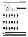
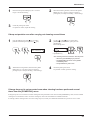
Unpacking the CAMMJET
Unpacking the CAMMJET
1 Checking Accessories
Check the following to make sure that you received all the items that were shipped with the unit.
Power cord: 1
Drain bottle: 1
Drain-bottle cap: 1
Screws: 2
Blade: 1
Blade holder : 1
Replacement blade for
separating knife: 1
Cleaning kit: 1
Roland COLORCHOICE®
CD-ROM: 1
Roland COLORCHOICE®
installation guide: 1
User’s manual: 1
11
Unpacking the CAMMJET
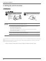
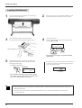
2 Setting Up and Connection
Setting Up
Unpacking, installation, and moving
must be carried out by two or more
persons.
Install in a level and stable location.
Otherwise the unit may tip over and cause
injury.
Failure to do so
may result in
falling of the
unit, leading to
injury.
NOTICE
Be sure to install the drain bottle before switching on the power.
Never install the unit in any of the following situations, as it could result in breakdown or faulty operation:
Places where the installation surface is unstable or not level.
Places with excessive electrical noise.
Places with excessive humidity or dust.
Places with poor ventilation, because the CJ-500 generates considerable heat during operation.
Places with excessive vibration.
Places exposed to strong illumination or direct sunlight.
Never step or stand on the stand legs, as doing so may damage them.
Do not place objects on the unit, as doing so may result in breakdown.
For an explanation of how to assemble the unit and the stand (PNS-501), refer to the “ASSEMBLY INSTRUCTIONS” included with the
stand.
When using the unit while mounted on a stand, be sure to ensure a sufficient amount of installation space for the unit. The required
installation spaces for this model are listed below.
2700 mm (106-5/16 in.) wide, 900 mm (35-7/16 in.) depth, and 1500 mm (59-1/16 in.) high
12
Unpacking the CAMMJET
Connection
NOTICE
Use only with a power supply of the
same rating as indicated on the unit.
Ground the unit with the ground
wire.
Use with any other power supply may lead
to fire or electrocution.
Failure to do so may result in risk of
electrical shock in the even of a mechanical
problem
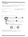
Before connecting the cable, make sure the computer's power and the CJ-500s main power switch are switched
off.
Securely connect the power cord, computer I/O cable and so on so that they will not be unplugged and cause
failure during operation. Doing so may lead to faulty operation or breakdown.
Arrange the power cord and interface connection cable to prevent tripping when moving around the unit.
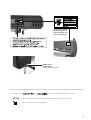
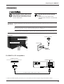
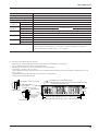
Rear View
Power connector
Power Connector
Parallel Connector
Power outlet
Power cord
For IBM PC or PC compatibles
Parallel connector
Secure the cable in place with the clips.
Parallel connector
Parallel interface cable (Printer cable)
* Cables are available separately. One which you are sure matches the model of computer being used should be selected.
13
Unpacking the CAMMJET
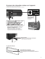
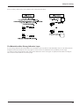
For Macintosh
Parallel connector
Secure the cable in place with the clips.
Parallel card for
Macintosh (optional)
Parallel interface cable (Printer cable)
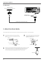
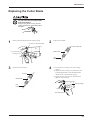
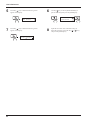
3 Attach the Drain Bottle
*The tube plug and the cap for the drain bottle are required when moving the machine, so do not discard them.
1
Detach the tube plug from the tube tips protruding
from the bottom surface of the right-hand side of the
unit.
2
Pass the tube through the hole in the drain-bottle
mounting cap and align with the threaded hole.
Tighten the included screws.
Tube
Tube plug
3
Drain-bottle cap
Remove the cap for the drain bottle and attach the drain bottle to the unit by screwing
it on in the direction of the arrow. Line up the threads on the drain bottle with the
threads on the unit, and screw on the bottle without applying excessive force.
Leave this mounted unless transporting the main unit, or when it is full.
Drain bottle
14
Unpacking the CAMMJET
Disposal of Discharged Ink
When the ink is about to exceed the “Upper Limit” line on the drain bottle, or when moving the machine, follow the steps below to
discard the ink.
If any ink gets on your hands or clothing, wash it off as soon as possible. Ink stains will become difficult to remove
if allowed to dry
1
Press the [POWER] key to switch off the power.
The POWER LED goes out
2
Remove the drain bottle
and attach the tube plug to
the tube tips instead.
Drain bottle
3
Put a water-absorbent, combustible material such as a
paper or cloth into the plastic bag, and soak up the ink.
4
Tube plug
Close the plastic bag,
and dispose of it as
combustible rubbish or
incinerate.
Combustible
material such as a
paper or cloth
Incineration
Combustibles
15
Unpacking the CAMMJET
4 Installing Ink Cartridges
Store ink cartridges out of the reach
of children.
NOTICE
If ink contacts the eyes, flush
immediately with water.
Do not remove any ink cartridges except when shipping the CJ-500.
If ink runs out, replace immediately with an ink cartridge designed especially for the CJ-500 (see "Maintenance
-- Replacing the Ink Cartridges"). Do not attempt to refill and reuse an empty ink cartridge.
If an ink cartridge is removed, replace it immediately with a new one.
Do not attempt to disassemble an ink cartridge.
Unused ink cartridges should be stored unopened at a temperature of -20°C (-4°F) to 40°C (104°F).
If an ink cartridge is dropped, the shock due to the fall may damage the ink cartridge and make it unusable.
- If any ink gets on your hands or clothing, wash it off as soon as possible. Ink stains will become difficult to remove
if allowed to dry.
- Once an ink cartridge has been installed, do not remove it until the ink has been used up. Frequent insertion and
removal may allow air to enter the ink tube and result in a drop in printing quality due to dot drop-out.
16
Unpacking the CAMMJET
Insert ink cartridges into the ink-cartridge ports. Insert it firmly, as far as it will go.
Ink cartridge ports
PIGMENT = pigment ink
DYE = dye ink
When inserting the cartridge, make sure that it is
inserted into the correct slot for that color.
PIGMENT CMYKLcLm (Pigment ink : cyan, magenta, yellow, black, light cyan, and light magenta)
PIGMENT
Black
PIGMENT
Cyan
PIGMENT
Magenta
PIGMENT
Light cyan
PIGMENT
Light magenta
PIGMENT
Yellow
PIGMENT CMYKOrGr (Pigment ink : cyan, magenta, yellow, black, orange, and green)
PIGMENT
Black
PIGMENT
Cyan
PIGMENT
Magenta
PIGMENT
Orange
PIGMENT
Green
PIGMENT
Yellow
DYE CMYKLcLm (Dye ink : cyan, magenta, yellow, black, light cyan, and light magenta)
DYE
Black
DYE
Cyan
DYE
Magenta
DYE
Light cyan
DYE
Light magenta
DYE
Yellow
When the power is turned on for the first time, or turned on after removing the ink, the system will execute ink fill.
This operation takes several minutes.
17
Unpacking the CAMMJET
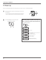
5 Power up
Be sure to mount the drain bottle before turning on the power. Refer to section "3 Attach the Drain Bottle".
1
When using for the first time turn on the main power switch on the
rear of the unit.
* Leave the main power switch on, and turn the power off and on in
daily use with the sub power switch on the front of the machine.
2
Press the [POWER] key on the operation panel.
The POWER LED lights up
When the power is turned on for the first
time, or turned on after removing the ink
The POWER LED lights up
Roland CJ-500
Ver.1.00
Roland CJ-500
UNKNOWN INK TYPE
No ink is filled.
SELECT INK TYPE
PIG.CMYKLcLm
Use the [ ] [ ] key to select the installed ink type
and press the [ENTER] key.
PIG. CMYKLcLm/PIG. CMYKOrGr/DYE CMYKLcLm
18
INSTALL
DRAIN TANK
Attach the drain tank, and
press the [ENTER] key.
NOW FILLING INK
The system will execute ink fill.
This operation takes several minutes.
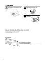
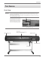
Part Names
Part Names
Front View
NOTICE
If you leave the printing head being uncapped for a long time (for example, opening the front cover while
print head is on the middle of platen), printing heads may get clogged and, in some cases result in unrecoverable damage to the printing head.
When the printing carriage is stopped on the platen, press the [POWER] key to reset the power. The carriage
moves and the printing head is capped.
Do not touch the rail or place the hands
inside the right-hand cover except when
adjusting the height of the printing head.
Touching the area shown may cause the
fingers to be soiled by grease or ink, and
may result in diminished image quality.
Rail
Do not put hands inside
Front cover
Sheet Loading Lever
If the cover is opened while printing or
cutting, the machine will stop.
Operation panel
Ink cartridge ports
Drain bottle
19
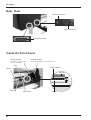
Part Names
Rear View
Main power switch
Power Connector
Parallel Connector
Inside the Front Cover
Cutting carriage
Printing carriage
The cutting carriage is where
the cutter is mounted.
When not printing, this stays inside the cover.
Rail
Cutter protector
Platen
Grit roller
Grit roller
20
Pinch roller
Platen
Part Names
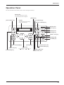
Operation Panel
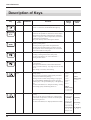
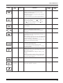
For more information about the keys, take a look at "Description of Keys".
BUSY LED
This flashes while data is being
received from the host computer.
[MENU] key
[TEST PRINT] key
Display
[CUT CONFIG] key
This show the various setting
menus, and messages.
[PRINT CONFIG] key
SETUP LED
[SETUP] key
PAUSE LED
[PAUSE] key
[SHEET CUT] key
POWER LED
[POWER] key
[TOOL UP/DOWN] key
[TEST CUT] key
([
[CLEANING] key
[ENTER] key
Arrow keys
] [ ] [
] [
])
ALIGN POINT LED
[ALIGN POINT] key
[BASE POINT] key
BASE POINT LED
21
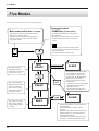
Five Modes
Five Modes
The CJ-500 has the following five modes (operating states).
Main power switch (Rear of CJ-500)
Sub power switch
POWER key (control panel)
Turn on when you first use the system, and after
that point it is generally left on.
Please do not turn it off unless transporting the
main unit, or if the system is not to be used for
long periods of time.
Use this switch to turn power on and off in
daily operation.
When power is turned on the system will enter
the NOT READY state (power on but sheet
not set).
When the power is turned on for the first time,
or turned on after removing the ink, the system
will execute ink fill.
This operation takes several minutes.
This mode is in effect
immediately after the
POWER key is pressed to
switch on the CJ-500.
This is the state where
material has been loaded
and its size detected.
The CJ-500 can accept
data from the computer
when in this mode.
NOT
READY
READY
SLEEP
The SLEEP mode is enabled when
the CJ-500 has been inactive for
a specified time. (When in the
SLEEP mode, the POWER LED
flashes once per 2 seconds.)
Any action of following cancels
SLEEP mode.
- Touch any key on the control panel.
- Send data from the computer.
- Open the front cover.
- Operate the sheet loading lever.
PAUSE
The CJ-500 is receiving
data from the computer
and performing printing
or cutting
22
BUSY
Pressing the PAUSE key causes operation to
stop temporarily.
Press the PAUSE key again to resume
operation.
Pressing the SETUP key while paused causes
remaining data to be cleared and returns to
the NOT READY mode.
If the material is removed while paused, the
CJ-500 goes into the NOT READY mode.
Setup for Printing
Setup for Printing
1 Loading the Material
Roll material must be placed at a
predetermined shaft position.
Failure to do so may
result in dropping the
roll, leading to injury.
Acceptable material widths
90 mm to 1371 mm (3.5 in. to 54 in.)
* N O T E : when loading material with a width
of 90 mm to 430 mm (3.5 in. to 17 in.), set the
[EDGE SENSE] menu item to [DISABLE].
Loading Roll Material
1
Tighten loosely with the screws.
Pass the stoppers onto both ends of the shaft.
(The shafts (2 pieces), stoppers (2 pieces), and screws
(2 pieces) are included with the stand.)
Shaft
* When passing the shaft through the stopper,
be sure to loosen the screws on the stopper
first.
Stopper
2
Align the media flange with the roll sheet edges, matching the roll sheet center ID.
(The media flange is included with the stand.)
Media flange
Media flange
Media flange
50.8 mm
(2 in.)
76.2 mm
(3 in.)
23
Setup for Printing
3
4
Set the two shafts in place and apply the brake.
Place the rolled material on the shaft.
Pass the end of the material between the pinch rollers
and the grit rollers so that it extends from the front of
the unit.
Shafts
Rear
Rear
Brake
5
When viewed from the front, align so that the lefthand edge of the material is above any of the grit
rollers and the right-hand edge is above the long grit
roller.
Roll material
6
Align the material so that it is perfectly straight,
and move the left-hand and right-hand pinch rollers
so that they are above the grit rollers.
Position the middle pinch roller over the grit roller that
lies between the left- and right-hand pinch rollers.
* The white stickers on the rail portion are
guides for positioning the grit rollers.
Rail
Grit rollers
Grit roller
(Right)
Pinch roller (left)
* Position the left and right
pinch rollers over the material,
near the edges.
24
Pinch roller (middle)
* Pull out the material
until it engages the
sensor.
Pinch roller (right)
* Make sure that the righthand edge of the material
does not extend beyond
the right-hand edge of the
grit roller.
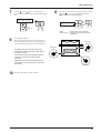
Setup for Printing
7
Align the left- and right-hand stoppers with the width
of the material and tighten the screws to secure in
place.
Rear
Media flange
Roll material
Screw
Stopper
8
From the front of the machine, pull the center of
material straight out toward the front. Without letting
any part of the entire piece of material pulled out to
become slack, move the sheet loading lever all the
way to “LOAD.”
The pinch rollers lower to hold the material in place.
Rear
Entire material
stretched taut
Sheet loading lever
* If there is any slack in the loaded material, the material may
move at an angle and come loose from the pinch rollers.
9
Close the front cover.
] and [
] keys to select [ROLL], then
Use the [
press the [ENTER] key.
SETUP SHEET
ROLL EDGE PIECE
*If printing is to be performed from the edge of
the material, select [EDGE] (If [EDGE] does not
appear, set [EDGE SENSE] to [ENABLE]).
10
Press the [SETUP] key. This detects the width of the
material and shows the printable width on the display.
*When [EDGE] is selected in step 9, the width of
the loaded material is detected, then the front
edge of the material is aligned with the print-start
location.
The SETUP LED lights up
If a pinch roller is positioned over an area where there is
no grit roller, the message shown below appears when
you press the [SETUP] key.
PINCHROLL ERROR
INVALID LEFTPOS
or [RIGHT]
Top menu
W1000mm
FINE
L ---mm
BI-DIR
Check the positioning of the pinch rollers and make
sure they are aligned at the correct positions.
25
Setup for Printing
Loading Flat Material
1
Pass the material between the pinch rollers and the grit
rollers as shown in the figure.
2
Refer to steps 5 and 6 in "Loading Roll Material," and
position the material and the pinch rollers correctly.
4
Close the front cover.
] and [
] keys to select [PIECE], then
Use the [
press the [ENTER] key.
Pass the material
3
Move the sheet loading lever toward LOAD.
The pinch rollers lower to hold the material in place.
SETUP SHEET
ROLL EDGE PIECE
Sheet loading lever
If [PIECE] does not appear, set [EDGE SENSE]
to [ENABLE].
5
Press the [SETUP] key. This detects the width and
length of the material and shows the printable width
and length on the display.
The SETUP LED lights up
Top menu
W1000mm
FINE
L1230mm
BI-DIR
If a pinch roller is positioned over an area where there is
no grit roller, the message shown below appears when
you press the [SETUP] key.
PINCHROLL ERROR
INVALID LEFTPOS
or [RIGHT]
*If the material is misaligned and looks like it might
come loose from the pinch rollers, or actually does
come loose, please reload the material.
Check the positioning of the pinch rollers and
make sure they are aligned at the correct positions.
- When loading flat material, if the material touches the shaft or roll material at the back of the machine, remove the
shaft and roll material.
- When thick material is loaded, adjust the head height. For more information, see "User's Reference -Adjusting the Height of the Printing Head."
- When changing to a different type of material, it is necessary to carry out feed correction and bi-directional correction. For more information, see "User's Reference -- Making Corrections for Printing."
- If the sides of the material have warped, then bend back the warp or feed the warped portion to the front and
perform setup again. Performing printing with a warped piece of material may cause head smudging or jamming of
the material. If the printing heads become damaged or soiled as a result, printing accuracy may suffer.
26
Setup for Printing
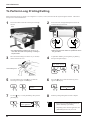
2 Test Printing
Printing quality is greatly affected by the state of the printing heads.
Before starting to print, you can do a test print to check the state of the printing heads.
If problems such as dot drop-out occur, printing quality drops.
If the test results show a problem, carry out head cleaning to restore the head to its normal state, then perform another test print.
1
Load a material, then close the front cover.
2
Hold down the [TEST PRINT] key for 1 second or longer to execute [TEST PRINT].
If there are any missing dots or other evidence
of a drop in printing quality, clean the head
(see "Maintenance -- Cleaning the Printing
Heads").
27
Setup for Printing
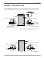
3 Setting the Printing Mode and Printing Direction
Before starting to print, set the printing mode and printing direction.
On the control panel, press the [PRINT CONFIG] key and specify the printing mode and direction of printing.
- Printing quality and output time vary according to the printing mode. Choose a mode that matches the task.
Note that when the printing mode is set on the computer, the computer’s setting takes priority.
- The printing time for the same original data becomes increasingly longer in this sequence: DRAFT, FAST,
NORMAL, FINE, FINE2, SUPER, and PHOTO. Also, with this procedure, the size of the output file generally
grows larger, and the processing time for creating the output file also becomes longer.
It's also necessary to ensure enough memory on the computer.
Printing Mode
Printing Direction
PHOTO:
This is suitable for printing photographs.
SUPER:
This is suitable for output with high image
quality, such as posters.
UNI-DIRECTION:
Uni-directional printing.
Printing is performed as the carriage moves from right to left.
Printing quality is better than with [BI-DIRECTION].
FINE:
This is suitable for output with comparatively
high detail, such as posters.
FINE2:
(Factory
default)
This is suitable for outputting posters and the
like on various materials.
NORMAL:
This is suitable for printing large-size items
with comparatively high quality in a short
time.
FAST:
This is suitable for printing large-size items in
a short time.
DRAFT:
This can produce output in the shortest time. It
is suitable for checking layout and the like.
1
Press the [PRINT CONFIG] key.
BI-DIRECTION (factory default):
Bi-directional printing.
Printing is performed as the carriage moves from right to left,
and also as it returns from left to right.
Printing speed is faster than with [UNI-DIRECTION].
2
Use the [
mode.
] and [
PRINT MODE
FINE
3
Press the [
] key to make the setting for the printing
direction.
Use the [ ] and [ ] keys to display the printing
direction, then press the [ENTER] key.
DIRECTION
BI-DIRECTION
28
] keys to choose the printing
Setup for Cutting
Setup for Cutting
1 Loading the Material
Roll material must be placed at a
predetermined shaft position.
Failure to do so may
result in dropping the
roll, leading to injury.
Acceptable material widths
90 mm to 1371 mm (3.5 in. to 54 in.)
* N O T E : when loading material with a width
of 90 mm to 430 mm (3.5 in. to 17 in.), set the
[EDGE SENSE] menu item to [DISABLE].
Loading Roll Material
1
Tighten loosely with the screws.
Pass the stoppers onto both ends of the shaft.
(The shafts (2 pieces), stoppers (2 pieces), and screws
(2 pieces) are included with the stand.)
Shaft
* When passing the shaft through the stopper,
be sure to loosen the screws on the stopper
first.
Stopper
2
Align the media flange with the roll sheet edges, matching the roll sheet center ID.
(The media flange is included with the stand.)
Media flange
Media flange
Media flange
50.8 mm
(2 in.)
76.2 mm
(3 in.)
29
Setup for Cutting
3
4
Set the two shafts in place and apply the brake.
Shafts
Place the rolled material on the shaft.
Pass the end of the material between the pinch rollers
and the grit rollers so that it extends from the front of
the unit.
Rear
Rear
Brake
5
When viewed from the front, align so that the lefthand edge of the material is above any of the grit
rollers and the right-hand edge is above the long grit
roller.
Roll material
6
Align the orientation of the material so that it is
perfectly straight, and move the left-hand and righthand pinch rollers so that they are above the grit
rollers.
Position the middle pinch roller over the grit roller that
lies between the left- and right-hand pinch rollers.
* The white stickers on the rail portion are
guides for positioning the grit rollers.
Rail
Grit rollers
Grit roller
(Right)
Pinch roller (left)
* Position the left and right
pinch rollers over the material,
near the edges.
30
Pinch roller (middle)
* Pull out the material
until it engages the
sensor.
Pinch roller (right)
* Make sure that the righthand edge of the material
does not extend beyond
the right-hand edge of the
grit roller.
Setup for Cutting
7
Align the left- and right-hand stoppers with the width
of the material and tighten the screws to secure in
place.
Rear
Media flange
Roll material
Screw
Stopper
8
From the front of the machine, pull the center of
material straight out toward the front. Without letting
any part of the entire piece of material pulled out to
become slack, move the sheet loading lever all the
way to “LOAD.”
The pinch rollers lower to hold the material in place.
Rear
Entire material
stretched taut
Sheet loading lever
* If there is any slack in the loaded material, the material may
move at an angle and come loose from the pinch rollers.
9
Close the front cover.
] and [
] keys to select [ROLL], then
Use the [
press the [ENTER] key.
SETUP SHEET
ROLL EDGE PIECE
*If cutting is to be performed from the edge of the
material, select [EDGE] (If [EDGE] does not
appear, set [EDGE SENSE] to [ENABLE]).
10
Press the [SETUP] key. This detects the width of the
material and shows the printable width on the display.
*When [EDGE] is selected in step 9, the width of
the loaded material is detected, then the front
edge of the material is aligned with the print-start
location.
The SETUP LED lights up
If a pinch roller is positioned over an area where there is
no grit roller, the message shown below appears when
you press the [SETUP] key.
PINCHROLL ERROR
INVALID LEFTPOS
or [RIGHT]
Top menu
W1000mm
FINE
L ---mm
BI-DIR
Check the positioning of the pinch rollers and make
sure they are aligned at the correct positions.
31
Setup for Cutting
Loading Flat Material
1
Pass the material between the pinch rollers and the grit
rollers as shown in the figure.
2
Refer to steps 5 and 6 in "Loading Roll Material," and
position the material and the pinch rollers correctly.
4
Close the front cover.
] and [
] keys to select [PIECE], then
Use the [
press the [ENTER] key.
Pass the material
3
Move the sheet loading lever toward LOAD.
The pinch rollers lower to hold the material in place.
SETUP SHEET
ROLL EDGE PIECE
Sheet loading lever
If [PIECE] does not appear, set [EDGE SENSE]
to [ENABLE].
5
Press the [SETUP] key. This detects the width and
length of the material and shows the printable width
and length on the display.
The SETUP LED lights up
Top menu
W1000mm
FINE
L1230mm
BI-DIR
If a pinch roller is positioned over an area where there is
no grit roller, the message shown below appears when
you press the [SETUP] key.
PINCHROLL ERROR
INVALID LEFTPOS
or [RIGHT]
*If the material is misaligned and looks like it might
come loose from the pinch rollers, or actually does
come loose, please reload the material.
- When loading flat material, if the material touches the shaft or roll material at the back of the machine, remove the
shaft and roll material.
- If the sides of the material have warped, then bend back the warp or feed the warped portion to the front and
perform setup again.
32
Setup for Cutting
2 Installing a Blade
Do not touch the tip of the blade
with your fingers.
Doing so may result in injury, and the
cutting performance of the blade will be
impaired.
NOTICE
1
Be sure to support the tool mounting screw from below when installing the blade holder.
Cutting quality may become poor if installed without supporting the screw in this way.
Insert a blade into the blade holder until it snaps into
place with an audible click.
2
Adjust the amount of blade extension as shown in
figure to find the optimal amount of blade for the
target material.
Turning the tip by an amount
corresponding to one large
scale gradation extends the blade by
0.1 mm (0.00394 in.).
Adjustment for 0.5 mm (0.0197 in.)
can be made by rotating the
cap one full turn.
Push-pin
Blade holder
0.1 mm
(0.00394 in.)
Blade
Min. : 0 mm
3
(1) Loosen the tool securing screw on the cutting
carriage.
(2) Support the tool-securing screw from below and
install the blade holder. Insert the blade holder
until the collar is flush with the carriage.
(3) Tighten the tool securing screw until the blade
holder is secured in place.
Max. : 2.5 mm
(0.0984 in.)
When cutting is performed after printing,
the cap tip of the blade holder may scratch
the printed surface. If this is the case,
lengthen the cutter blade extension.
Cutting carriage
Loosen
Tighten
Tool securing screw
33
Setup for Cutting
3 Test Cutting
Cutting quality is affected by the blade and material being used, and by the cutting conditions. There are four cutting conditions: “cutting
speed,” “blade force,” “blade offset,” and “amount of blade extension.” For high-quality cutting, it is necessary to set the appropriate
cutting conditions for the blade and material in actual use.
The test cut is a feature for checking beforehand whether these cutting conditions are appropriate.
1
Install a blade and load a material, then close the front
cover.
2
3
Press the [TEST CUT] key for 1 second or longer.
Test cutting starts.
4
Examine the cutting results for the material and diagnose the cutting conditions.
Use the [ ] , [ ] , [
] and [
] keys to move
the tool carriage to the place where the test cutting is
to be performed.
(1) Peel off the round section (marked by
).
When it can be peeled by itself, without disturbing the square (marked by
), the
cutter force is set appropriately. If both the circle and square peel off, either the
“blade force” or the “amount of blade extension” is insufficient.
(2) Remove the square section (marked by
).
The optimum blade pressure is correct if you can clearly make out the lines left by the
blade.
If the blade trace is indistinct or too strong, you need to adjust the “blade force” or the
“amount of blade extension.”
(3) Check the shape of the rectangle.
- If the corners are cut securely as shown in A, there conditions are correct.
- If the corners are rounded as shown in B, the “blade offset” is insufficient.
- If the corners have “horns” as shown in C, the “blade offset” is too large
A
B
C
If the test cut shows problems, adjust the cutting conditions.
For “cutting speed,” “blade force,” and “blade offset,” press the [CUT CONFIG] key and set the cutting conditions.
For “amount of blade extension,” refer to “Setup for Cutting -- 2 Installing the Blade.”
Repeat the test cut and adjustment of the cutting conditions until you obtain good cutting results for the material.
34
Setup for Cutting
Incorrect cutting conditions may cause symptoms such as those described below.
For Materials with a Strong Adhesive Layer
If you are using a material with a strong adhesive layer, the adhesive layer may adhere to itself immediately when cut. This means that even
though the material has actually been cut, it may appear as if it has not been cut, and blade force may mistakenly be set too high.
If a cutting test shows that the material peels easily and the blade traces on the carrier paper are optimal, then the material is being cut.
Take care not to set the blade force excessively high.
35
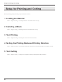
Setup for Printing and Cutting
Setup for Printing and Cutting
Before performing printing and cutting, set up the machine as follows.
1 Loading the Material
Refer to “Setup for Printing -- 1 Loading the Material” and load the material correctly.
2 Installing a Blade
Refer to “Setup for Cutting -- 2 Installing the Blade” and install the blade correctly.
3 Test Printing
Refer to “Setup for Printing -- 2 Printing Test” and check the state of the heads.
4 Setting the Printing Mode and Printing Direction
Refer to “Setup for Printing -- 3 Selecting the Printing Mode and Direction of Printing” and make the settings for the modes.
5 Test Cutting
Refer to “Setup for Cutting -- 3 Cutting Test” and perform a cutting test and adjust the cutting conditions.
36
Downloading Printing/Cutting Data
Downloading Printing/Cutting Data
NOTICE
Opening the front cover while printing is in progress causes an emergency stop. This means that printing may
not be carried out correctly even if operation is resumed, due to drop-out or misalignment of the image.
To pause printing for any other reason than an emergency stop, press the [PAUSE] key.
Note pressing the [PAUSE] key to pause operation may result in differing image quality before and after the
pause. It is a good idea to avoid pausing operation while printing is in progress whenever possible.
If you leave the print head uncapped for a long time (for example, open the front cover while print head is in
the middle of platen), print heads may get clogged and, in some cases it results in unrecoverable damage to the
print head.
Printing or cutting is started when data is sent from the computer.
If the top menu isn't displayed, printing or cutting doesn't start even when data is sent from the computer.
Conditions for starting printing or cutting
The material must be already set up (with the SETUP LED lighted),
and the display must show the top menu.
Top menu
W1234mm
FINE
L ---mm
BI-DIR
If another menu screen is displayed, press the [SETUP] key to go back to the top menu.
(Pressing the [SETUP] key when another menu screen is displayed does not cancel the set-up for the material.)
Pausing Printing or Cutting Operations
Press the [PAUSE] key.
To resume printing
Press the [PAUSE] key.
The PAUSE LED lights up
The PAUSE LED goes out
37
Downloading Printing/Cutting Data
Stopping Printing or Cutting Operations
1
Press the [PAUSE] key.
The PAUSE LED lights up
2
Halt transmission of print or cutting instructions from
the computer.
3
Hold down the [SETUP] key for one second or longer.
Any remaining data is cleared.
The SETUP LED goes out
* Clearing the data
may take some
time.
If the "INK EMPTY" message appears while printing
If it becomes necessary to replace the ink cartridge while printing is in
progress, the buzzer sounds and the following message is displayed.
Please replace the ink cartridge.
If this message is ignored and printing is continued without replacing the
ink cartridge, image quality may be adversely affected and exhibit
faintness or other problems.
1
When [INK CONTROL]'s [EMPTY MODE] is
set to [LATER]
INK EMPTY
[KCMcmY]
This indicates the ink color.
The color for which ink has run out flashes.
K = Black / C = Cyan / M = Magenta /
c = Light Cyan (O = Orange) /
m = Light Magenta (G = Green) / Y = Yellow
2
Pull out the cartridge for the ink color that has run out,
and replace with a new cartridge (see "Replacing the
Ink Cartridges").
3
Press the [PAUSE] key to resume printing.
Press the [PAUSE] key to pause printing.
The PAUSE LED lights up
The PAUSE LED goes out
When [INK CONTROL]'s [EMPTY MODE] is
set to [PROMPT]
The unit pauses automatically.
About the [EMPTY MODE]
When replacement of the ink cartridge becomes necessary while printing is in progress, this setting determines whether printing
continues or pauses.
This setting is used when the ink cartridge cannot be changed immediately during printing, such as during unattended operation at
night. [LATER] causes printing to continue without pause even if ink cartridge replacement becomes necessary. Printing continues with
the small amount of ink remaining, so the printed image may become faint as the ink runs out. In general, it should possible to perform
about 1 m2 (10 ft2) of printing once this message appears, although the actual amount varies widely according to the amount of ink needed
for the particular image. Printing is continued only for the data currently being printed. Operation stops after one image is output.
[PROMPT] causes operation to pause immediately when the ink cartridge needs to be changed. Printing is resumed by replacing the
cartridge and pressing the [PAUSE] key. Please note, however, that the colors of an image in progress may no longer be perfectly
matched if the unit is allowed to remain paused for two or three hours before resuming printing.
38
Removing the Material
Removing the Material
Removing the Material from the machine
1
Press the [SETUP] key. Hold down for about 1
second.
The SETUP LED goes out
2
Move the sheet loading lever toward the back of the
unit.
The pinch rollers rise to release the material.
Sheet loading lever
3
Open the front cover.
To remove the material.
Cut the material from the roll
Either of two methods can be used to separate a portion that's already been cut or printed from the roll. One method is to press the
[SHEET CUT] key. The other method is to perform separation automatically by sending a material-cutting command from the computer.
When separating the material by pressing the [SHEET CUT] key
Holding down the [SHEET CUT] key for 1 second or longer
severs the material at the present location of the blade tip.
The material is cut off here.
Present location of
the blade tip
Cut or printed
portion
* This operation isn't necessary when
sending a material-cutting command
from the computer to separate the
material automatically.
39
Removing the Material
When sending a material-cutting command from the computer
to separate the material automatically
* When the material-cutting command has not been set to "enabled" at the computer, automatic separation of
the material is not performed, even when the following setting is made.
1
Press the [MENU] key and [ ] key to make the
following screen appear on the display.
MENU
AUTO SHEET CUT
2
Press the [
] key to make the following screen
appear on the display.
The material-separating location during
continuous output
Start of the next output
35 mm
(1-1/8 in.)
AUTO SHEET CUT
DISABLE DISABLE
End of output
3
Use the [ ] key to select [ENABLE], then press the
[ENTER] key.
AUTO SHEET CUT
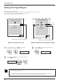
DISABLE ENABLE
Location where separated
35 mm (1-1/8 in.)
Margin (value set for [PAGE MARGIN])
40
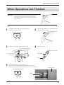
When Operations Are Finished
When Operations Are Finished
NOTICE
1
Sheet loading lever
When operations are finished, move the sheet loading lever
toward the back of the machine to raise the pinch rollers.
The pinch rollers may be deformed if allowed to remain in
the lowered state.
2
If the SETUP LED is lighted, press the [SETUP] key.
Hold down for about 1 second.
Move the sheet loading lever toward the back of the
unit and remove the material.
Sheet loading lever
The SETUP LED goes out
3
4
Remove the blade holder from the cutting carriage.
Remove the blade.
(2) Remove the blade holder
Press the push-pin
Blade holder
(1) Loosen the tool
securing screw
Blade
5
Press the [POWER] key to switch off the power.
The carriage moves to the standby position and the head is capped.
If the carriage is already at the standby position, no movement takes place.
Standby position
The POWER LED goes out
Carriage
41
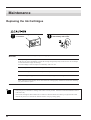
Maintenance
Maintenance
Replacing the Ink Cartridges
Store ink cartridges out of the reach
of children.
NOTICE
If ink contacts the eyes, flush
immediately with water.
Do not remove any ink cartridges except when shipping the CJ-500.
Use only the type of filled ink specified for the machine.
If ink runs out, replace immediately with an ink cartridge designed especially for the CJ-500. Do not attempt
to refill and reuse an empty ink cartridge.
If an ink cartridge is removed, replace it immediately with a new one.
Do not attempt to disassemble an ink cartridge.
Unused ink cartridges should be stored unopened at a temperature of -20°C (-4°F) to 40°C (104°F).
If an ink cartridge is dropped, the shock due to the fall may damage the ink cartridge and make it unusable.
When removing an ink cartridge, do not rush. Detach the cartridge gently. Sudden movement when detaching
may cause ink to be spilled.
- If any ink gets on your hands or clothing, wash it off as soon as possible. Ink stains will become difficult to remove
if allowed to dry
- Once an ink cartridge has been installed, do not remove it until the ink has been used up. Frequent insertion and
removal may allow air to enter the ink tube and result in a drop in printing quality.
42
Maintenance
1
Remove the ink cartridge from the ink-cartridge port.
2
Insert new ink cartridge.
PIGMENT = pigment ink
DYE = dye ink
Ink cartridge ports
Use only the type of ink currently filled in the machine.
The present ink type is displayed when the power is turned on.
Press the
Roland CJ-500
Ver.1.00
Roland CJ-500
PIGMENT CMYKLcLm
key
UNKNOWN TYPE = No ink is filled.
PIGMENT CMYKLcLm
= Pigment ink (cyan, magenta, yellow, black, light cyan, and light magenta)
PIGMENT CMYKOrGr
= Pigment ink (cyan, magenta, yellow, black, orange, and green)
DYE CMYKLcLm
= Dye ink (cyan, magenta, yellow, black, light cyan, and light magenta)
With pigment inks, do not insert ink cartridges for orange or green when using light cyan and light magenta. Also, do not
insert the ink cartridges for light cyan or light magenta when using orange and green.
If ink cartridges other than the filled type or color are installed, printed color will be inaccurate.
To change the type of ink, you must use an optionally available cleaning cartridge to flush the ink. For more information, see "Maintenance -- Changing the Type of Ink."
43
Maintenance
Check how much ink remains
You can use [INK LEFT] on the display menu to check how much ink is left after the ink cartridges have been installed.
Use this information as a guide for replacing the ink cartridges.
If a partially used ink cartridge is removed and reinstalled, or if a partially used ink cartridge is installed, the cartridge is "read" as
unused, and the amount of remaining ink is not accurate.
1
Press the [MENU] key and [ ] key to make the
following screen appear on the display.
MENU
INK LEFT
2
Press the [
] key to make the following screen
appear on the display.
The fewer the markers, the less is the amount of ink
left.
K
c
C
m
M
Y
K = Black / C = Cyan / M = Magenta /
c = Light Cyan (O = Orange) /
m = Light Magenta (G = Green) /
Y = Yellow
Remaining ink
Much
No marker
Little
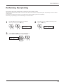
Cleaning the Printing Heads
Switching on the sub power automatically performs maintenance operations, including cleaning of the printing head. This means that
there is normally no need to perform cleaning otherwise.
If drop-out occurs with printed images, clean the printing head.
* After cleaning, carry out a printing test. Load material.
The cleaning causes a certain amount of head wear and also consumes a certain amount of ink, so use should be kept
to a minimum.
[POWERFUL] results in faster head wear and also uses up more ink. (Performing cleaning from the [POWERFUL]
menu uses up about 57 cc of ink (total) for six colors. This is because the process discharges all ink in the ink tube and
replaces it with fresh ink.)
44
Maintenance
1
Hold down the [CLEANING] key for 1 second or
longer to start head cleaning.
3
Check the printing-test results.
If a problem is found, repeat the cleaning.
2
When head cleaning finishes, hold down the [TEST
PRINT] key for 1 second or longer to perform a
printing test (see "Setup for Printing -- Test Printing").
If drop-out persists even after carrying out cleaning several times
1
Press the [MENU] key and [ ] key to display
[HEAD CLEANING], then press the [
] key.
2
Use the [ ] and [ ] keys to select either
[MEDIUM] or [POWERFUL], then press the
[ENTER] key.
Head cleaning starts.
HEAD CLEANING
MEDIUM
MENU
HEAD CLEANING
or [POWERFUL]
*The cleaning function increases in this sequence.
- When the [CLEANING] key is pressed
- The [MEDIUM] menu item on the [HEAD
CLEANING] menu
- The [POWERFUL] menu item
3
When head cleaning finishes, hold down the [TEST
PRINT] key for 1 second or longer to perform a
printing test (see "Setup for Printing -- Test Printing").
4
Check the printing-test results.
If a problem is found, repeat the cleaning.
If image drop-out is not corrected even when cleaning has been performed several
times from the [POWERFUL] menu
If image drop-out is not corrected even when cleaning has been performed several times from the [POWERFUL] menu, use the included
cleaning kit. For information on how to use the cleaning kit, refer to the documentation included with the kit.
If cleaning with the cleaning kit does not correct image drop-out, consult your authorized Roland DG Corp. dealer or service center.
45
Maintenance
Changing the Type of Ink
To change the type of ink in use, change the ink set on the LED.
Ink replacement requires three optionally available cleaning cartridges.
1
Press the [MENU] key and [ ] key to make the
following screen appear on the display.
2
INK CONTROL
EMPTY MODE
MENU
INK CONTROL
3
Use the [ ] key to select [CHANGE INK SET], then
press the [
] key.
Press the [
] key to make the following screen
appear on the display.
4
Use the [ ] and [ ] keys to select the new type of
ink to use, then press the [ENTER] key.
CHANGE INK SET
PIG.CMYKLcLm
INK CONTROL
CHANGE INK SET
PIG. CMYKLcLm
(Pigment ink : cyan, magenta, yellow, black, light cyan, and light magenta)
PIG. CMYKOrGr
(Pigment ink : cyan, magenta, yellow, black, orange, and green)
DYE CMYKLcLm
(Dye ink : cyan, magenta, yellow, black, light cyan, and light magenta)
5
When the display shown in the figure appears, discard
the discharged ink in the drain bottle.
* Be sure to discard the discharged ink.
Attempting to replace the ink while discharged ink
remains may cause discharged ink to overflow from
the bottle.
6
Remount the drain bottle and press the [ENTER] key to
display the screen shown in the figure.
REMOVE CARTRIDGE
[KCMcmY]
DISCARD
DRAIN INK
7
When all ink cartridges have been removed, ink
replacement starts. Follow the messages on the
display to carry out the procedure.
8
When the display shown in the figure appears, insert
the ink cartridge to be newly used.
SET CARTRIDGE
[KCMOGY]
Messages appearing during ink replacement
SET CL-LIQUID
[KCMcmY]
Insert a cleaning cartridge into the ink cartridge port
for the flashing color.
REMOVE CL-LIQUID
[KCMcmY]
Remove the cleaning cartridge from the ink cartridge
port for the flashing color.
K = Black C = Cyan M = Magenta c = Light Cyan (O = Orange)
m = Light Magenta (G = Green) Y = Yellow
46
9
When the display shown in the figure appears, ink
replacement is finished.
Press the [SETUP] key to go back to the top menu.
CHANGE INK SET
PIG.CMYKOrGr
Maintenance
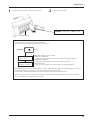
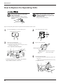
Replacing the Cutter Blade
Do not touch the tip of the blade
with your fingers.
Doing so may result in injury, and the
cutting performance of the blade will be
impaired.
1
Remove the blade holder from the cutting carriage.
2
Remove the old blade.
(2) Remove the blade holder
Press the push-pin
Blade holder
(1) Loosen the tool
securing screw
Old
blade
3
Replace with a new blade.
Push-pin
Blade holder
4
(1) Loosen the tool securing screw on the cutting
carriage.
(2) Support the tool-securing screw from below and
install the blade holder. Insert the blade holder
until the collar is flush with the carriage.
(3) Tighten the tool securing screw until the blade
holder is secured in place.
Cutting carriage
New
blade
Loosen
Tighten
Tool securing screw
47
Maintenance
How to Replace the Separating Knife
Make sure the power to the unit is
off before attempting to replace the
separating knife.
Do not touch the tip of the blade
with your fingers.
Doing so may result in injury, and the
cutting performance of the blade will be
impaired.
Doing so may result in injury.
Replace the separating knife with the replacement blade included with the CJ-500.
1
Press the [POWER] key to switch off the power.
3
Remove the separating knife.
(1) Loosen the screw until it slips out.
(2) Grasp the screw portion, and slowly pull it out in
the direction of the arrow.
* Do not pull back while doing this.
The POWER LED goes out
2
Turn off the main power switch.
4
Replace with a new knife.
Positioning groove
(2)
The knife is secured in
place by the magnet.
(1)
If the blade remains in the carriage, use commercially available tweezers to remove it.
5
Install the separating knife.
(1) Grasp the screw portion and slowly insert it into
the groove.
* Take care to ensure that the knife does not slip
(2) Tighten the screw.
(1)
(2)
48
Maintenance
When the Product Needs Cleaning
NOTICE
When performing cleaning, turn off the main power switch.
* Before turning off the main power, press the [POWER] key to switch off the sub power.
Never lubricate the mechanisms.
Use a small amount of water or ethyl alcohol for cleaning the covers. Never use solvents such as benzene or
thinner.
Periodically clean the platen. Attractive printing may become impossible if the platen is soiled.
Do not touch the printing heads or allow the printing heads to come in contact with anything except ink.
Cleaning the body
Use water or ethyl alcohol to clean, and wipe gently with a clean cloth. Wipe the operation panel and display gently with a clean, dry, and
soft cloth.
Cleaning the platen
If the platen is dirty clean with ethyl alcohol or water and wipe gently with a cloth.
Cleaning the grit rollers
Use a commercially available brush to remove dust and other detritus. Brush
horizontally while rotating the grit rollers.
Any adhering grime may prevent the material from being held in place securely.
Cleaning the pinch rollers
Use water or ethyl alcohol and clean with a soft cloth.
Cleaning the front cover
Use water or ethyl alcohol and clean with a soft cloth.
Cleaning the blade holder cap
If material debris is adhering to the inner surface of the cap for the blade holder, loosen and remove the cap, then remove the material
debris.
49
Maintenance
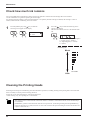
When Not in Use for a Prolonged Period...
NOTICE
When not in use, move the sheet loading lever toward the
back of the unit to leave the pinch rollers in the up position
state. The pinch rollers may be deformed if allowed to
remain in the lowered state.
Sheet loading lever
Do not switch off the main power with the printing head in an uncapped state (i.e., while the carriage is on the
platen).
If you leave the carriage uncapped for a long time, doing so may result in clogging of the printing head, making
it unusable.
Before switching off the main power, be sure to press the [POWER] key to switch off the sub power for the CJ500.
1
After carrying out steps 1
to 5 in "When Operations
are Finished" (p. 41) turn
off the main power switch.
2
Unplug the power cord from the electrical outlet.
* If the unit will be out of use for a month or longer, follow steps 1 through 9 of "When Moving the Unit..." to wash the printing heads.
Head washing requires three optionally available cleaning cartridges.
50
Maintenance
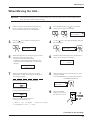
When Moving the Unit...
NOTICE
1
When moving the unit, first carry out head washing, then secure the carriage in place. Head washing requires
three optionally available cleaning cartridges.
If there is material loaded, hold down the [SETUP]
key for 1 second or longer to cancel setup, then
remove the material (see "Remove the Material").
2
Press the [MENU] key and [ ] key to make the
following screen appear on the display.
MENU
INK CONTROL
3
Press the [
] key to make the following screen
appear on the display.
4
Use the [ ] key to select [HEAD WASH], then press
the [ENTER] key.
INK CONTROL
EMPTY MODE
5
When the display shown in the figure appears, discard
the discharged ink in the drain bottle.
* Be sure to discard the discharged ink.
Attempting to head washing while discharged ink
remains may cause discharged ink to overflow from
the bottle.
INK CONTROL
HEAD WASH
6
Mount the drain bottle and press the [ENTER] key to
display the screen shown in the figure.
REMOVE CARTRIDGE
[KCMcmY]
DISCARD
DRAIN INK
7
When all ink cartridges have been removed, head
washing starts. Follow the messages on the display to
carry out the procedure.
8
When the display shown in the figure appears, head
washing is finished.
Press the [POWER] key to switch off the sub power.
The POWER LED goes out
Messages appearing during head washing
INK CONTROL
HEAD WASH
SET CL-LIQUID
[KCMcmY]
Insert a cleaning cartridge into the ink
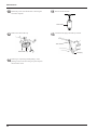
cartridge port for the flashing color.
REMOVE CL-LIQUID
[KCMcmY]
9
When the POWER
LED goes out, turn off
the main power switch.
Remove the cleaning cartridge from the ink
cartridge port for the flashing color.
K = Black C = Cyan M = Magenta c = Light Cyan (O = Orange)
m = Light Magenta (G = Green) Y = Yellow
Continued on the next page
51
Maintenance
10
Detach the power cord and the cable connecting the
unit to the computer.
11
Remove the drain bottle.
Drain bottle
12
Remove the drain-bottle cap.
13
Attach the tube plug to the tube tips instead.
Tube
Drain-bottle cap
14
52
Referring to "Unpacking and Repacking" on the
packing carton, secure the carriage in place and pack
the unit in the carton.
Tube plug
User's Reference
User's Reference
Setting the Start Point
Set the print or cutting start position (base point) to the desired location.
1
Load material and install a blade, then press the
[SETUP] key.
2
Use the arrow keys to align the blade with the new
printing or cutting start location (base point).
Align with
the center
of the blade
installed on
the cutting
carriage.
3
Press the [BASE POINT] key.
The BASE POINT LED lights up
When an align point has been set,
it is released if the [BASE POINT]
key is pressed.
To change the starting location that has been set...
• Set a new starting location in a different location.
• Press the [SETUP] key to cancel the setup for the material (making the SETUP LED go out).
53
User's Reference
Adjusting the Printing and Cutting Positions
When printing is followed by cutting, the cutting line may be displaced from the printing.
If this happens, use the display menu’s [PRINT-CUT ADJ.] function to align the printing and cutting positions.
Adjusting Automatically
1
Load some material and press the [SETUP] key.
2
Press the [MENU] key and [ ] key to make the
following screen appear on the display.
MENU
PRINT-CUT ADJ.
3
] key to make the following screen
Press the [
appear on the display.
4
Press the [ENTER] key to print crop marks and read
the crop marks automatically.
Rear
PRINT-CUT ADJ.
AUTO
Front
Crop mark
While automatic adjustment is in progress, the
following message appears on the display.
NOW PROCESSING...
5
When the following message appears, automatic
adjustment is finished.
PRINT-CUT ADJ.
COMPLETED!!
Depending on the type of material, the crop mark may not be read accurately.
54
User's Reference
Adjusting Manually
1
Load material and install a blade, then press the
[SETUP] key.
2
Press the [MENU] key and [ ] key to make the
following screen appear on the display.
MENU
PRINT-CUT ADJ.
3
Press the [
] key to make the following screen
appear on the display.
4
Press the [ ] key to make the following screen
appear on the display.
PRINT-CUT ADJ.
AUTO
5
Press the [ENTER] key to print crop marks.
Rear
PRINT-CUT ADJ.
MANUAL
6
Use the arrow keys to align the center of the blade at
the lower-right corner of the crop mark.
Crop mark
Align with
the center
of the blade
installed on
the cutting
carriage.
Front
Crop mark
Center of the blade
After printing the crop mark, the following
message appears.
MOVE CURSOR AND
PRESS ENTER
7
Press the [ENTER] key to adjust the printing and
cutting positions.
55
User's Reference
Remove the Printed Material, then Reload the Material and Perform Cutting
-Setting the Base Point and the Align PointThis feature is for performing position alignment in cases where printing is performed, after which the material removed from the
machine for further processing (such as laminating), then again loaded on the machine for cutting.
When cutting off a piece of material that has been printed from a roll, then again loading it as [PIECE], make sure
there is 80 mm (3-3/16 in.) or more from where printing ended to the material’s end edge (the place where cut off
from the roll).
When cutting off the material automatically, set a page margin of 80 mm (3-3/16 in.) or more (see “Setting the Page
Margins”).
Adjusting Automatically
1
Press the [MENU] key and [ ] key to make the
following screen appear on the display.
2
Press the [
] key to make the following screen
appear on the display.
MENU
CROP MARK
3
Use the [ ] key to select [ENABLE], then press the
[ENTER] key.
CROP MARK
DISABLE DISABLE
4
Send the printing data from the computer.
Three crop marks are automatically printed on the left
and right areas at the front edge of the material.
CROP MARK
DISABLE ENABLE
Rear
Front
* Setting [CROP MARK] to [ENABLE] makes the
output area 25 mm (1 in.) narrower.
Crop marks
5
When printing is finished press the [SET UP] key,
remove the material and carry out lamination (or
whatever further processing needs to be done).
After processing, load the material at the same pinchroller positions used during printing.
6
Use the [ ] and [ ] keys to position the material so
that the lower-right crop mark lies on an imaginary
line extending from the blade tip.
Cutting
carriage
Imaginary
line from the
blade tip
Lower-right crop mark
Blade tip
56
User's Reference
7
Use the [
] and [
] keys to select the type of
material that is loaded, then press the [BASE POINT]
key.
8
SETUP SHEET
ROLL EDGE PIECE
When the screen shown in the figure appears, use the [
] and [ ] keys to choose [BASE] or [BASEALIGN], then press the [ENTER] key.
AUTO CROP MARK
BASE
BASE
BASE-ALIGN
9
Press the [SET UP] key.
The crop marks printed in step 4 are detected automatically, and the base point and the align points (if
you selected [BASE-ALIGN]) are set and adjusted.
:Only the base point is detected.
:The base point and the align points
are detected.
Align point
Align point
*The align point cannot be set if the angle
between the base point and the align point is
5 degrees or more.
*Crop marks drawn with computer programs
cannot be used as crop marks by this
machine.
*Depending on the kind of lamination that’s
performed, the crop marks may not be read
accurately.
10
Base point
Send the cutting data from the computer.
57
User's Reference
Adjusting Manually
1
Follow steps 1 through 4 for making the setting
automatically on the previous pages, then perform
printing.
3
Install a blade on the cutting carriage.
4
Set the base point.
Use the arrow keys to align the blade at the place on
the lower-right crop mark shown in the figure, then
press the [BASE POINT] key.
2
When printing is finished press the [SET UP] key,
remove the material and carry out lamination (or
whatever further processing needs to be done).
Load the material at the same pinch-roller positions
used during printing, then press the [SETUP] key.
5
Set the align point.
Use the arrow keys to align the blade at the place on
the lower-left or upper-right crop mark shown in the
figure, then press the [ALIGN POINT] key.
Align point
Center of the
blade
Center of the
blade
Base point
Center of the
blade
Align point
Align the
center of
the blade
with the
base point
or the align
point.
6
58
*The align point cannot be set to both the lower left and upper right points.
*The align point cannot be set if the angle between the base point and the align
point is 5 degrees or more.
*Crop marks drawn with computer programs cannot be used as crop marks
by this machine.
Send the cutting data from the computer.
User's Reference
Making Corrections for Printing
Feed Correction
This corrects for errors in the amount of feed of the grit rollers due the type of material.
Be sure to make this setting when you have replaced the material with a different type.
Correcting the amount of feed improves the dot-positioning accuracy in the feed direction, which can help enhance image quality.
When performing test printing for feed correction, load the material correctly (see "Setup for Printing -- Loading the
Material"). If the material is not loaded correctly, an accurate test pattern may not be output.
1
Press the [MENU] key and [ ] key to make the
following screen appear on the display.
2
Press the [
] key to make the following screen
appear on the display.
MENU
CALIBRATION
3
CALIBRATION
PRINTING ADJ.
4
Press the [
] key to make the
following screen appear on the display.
Press the [ENTER] key to start printing a test pattern.
Test pattern
PRINTING ADJ.
TEST PRINT
+0.30%
+0.25%
* Printing a Pattern
in Steps of 0.10%
5
+0.20%
Check the test pattern and choose a
value with no displacement.
+0.15%
Value with no
displacement
+0.10%
+0.05%
6
0.00%
Press the [ ] key to make the following screen
appear on the display.
-0.05%
-0.10%
PRINTING ADJ.
ADJUST
7
Press the [
] key to make the following screen
appear on the display.
ADJUST
-0.10%
-0.10%
Current
setting
-0.15%
8
Use the [ ] and [ ] keys to set the value you
checked in step 4, then press the [ENTER] key.
ADJUST
-0.10%
+0.20%
-2.0% to +2.0%
(In steps of 0.05%)
* Test printing prints the pattern in steps of 0.10%.
59
User's Reference
Bidirectional Correction
* Only when the printing direction at the [PRINT MODE] menu has been set to [BI-DIRECTION] (bidirectional)
This adjusts slippage when performing bidirectional printing.
Make this adjustment when you have replaced the material with a different type or adjusted the head height.
1
2
Press the [MENU] key and [ ] key to make the
following screen appear on the display.
Press the [
] key to make the following screen
appear on the display.
MENU
BIDIRECTION
3
BIDIRECTION
TEST PRINT
4
Press the [ENTER] key to start printing a test pattern.
Check the test pattern and choose a value with no
displacement.
Test pattern
Current setting
+15 +14 +13 +12 +11 +10 +9 +8 +7 +6 +5 +4 +3 +2 +1
0
-1
-2
-3
-4
-5
-6
-7
-8
-9 -10 -11 -12 -13 -14 -15
Value with no displacement
5
Press the [ ] key to make the following screen
appear on the display.
BIDIRECTION
ADJUST
7
Use the [ ] and [ ] keys to set the value you
checked in step 4, then press the [ENTER] key.
ADJUST
+0
+5
-15 to +15 (In steps of 1)
60
6
Press the [
] key to make the following screen
appear on the display.
ADJUST
+0
+0
User's Reference
Aligning the Printing Length and Cutting Length
There is normally no need to adjust this. When there is no effect due to expansion or contraction of the material, use the machine with the
calibration value always set at “0.”
However, when printing is followed by cutting, the cutting length may be displaced from the printing length.
This is because the material may absorb moisture from the ink or the air, making it expand or contract. The degree of expansion or
contraction varies depending on the composition of the material, the composition of the base paper, and the temperature and humidity
where installed. In general, highly absorbent materials are more susceptible to expansion and contraction.
At such times, use the display menu’s [CALIBRATION_CUTTING ADJ.] function to adjust the cutting length with respect to the
printing length.
The calibration value that you set persists even after the power is switched off. After performing output, return the calibration value to
“0.”
In the following case, the cutting-distance correction value is set automatically, and the setting made here is ignored.
- When the [BASE POINT] key is pressed when loading the material and the base point and align point are detected automatically
1
To calculate the correction value, measure the lengths of A, B, C and D in the following diagram.
Cutting line
Printing result
C Misalignment in the feed direction
Rear
+
–
Front
*Feed direction
.....The direction of
material feed
*Scan direction
.....The direction of
carriage movement
D
Printing length
in the feed
direction
B
Printing length in
the scan direction
+
–
A Misalignment in the scan direction
2
3
Calculate the percentage of cutting-length displacement relative to the printing length.
Correction value in
FEED direction.
C
Offset in FEED direction.
=
D
Offset of FEED-direction data.
X 100
Correction value in
SCAN direction.
A
Offset
in
SCAN
direction.
=
B
Offset of SCAN-direction data.
X 100
Press the [MENU] key and [ ] key to make the
following screen appear on the display.
MENU
CALIBRATION
4
* If the cutting line is in the + direction from the printing position, then
input the correction as a -.
If the cutting line is in the - direction
from the printing position, then
input the correction as a +.
Press the [
] key and [ ] key to make the
following screen appear on the display.
CALIBRATION
CUTTING ADJ.
Continued on the next page
61
User's Reference
5
Press the [
] key to make the following screen
appear on the display.
6
CUTTING ADJ.
SCAN ADJUST
CUTTING ADJ.
FEED ADJUST
7
Press the [
] key to make the following screen
appear on the display.
SCAN ADJUST
+0.00% +0.00%
62
Use the [ ] key to choose [FEED ADJUST] or
[SCAN ADJUST], then press the [ENTER] key.
8
Input the correction value calculated in step (2).
Select the correction value with the [ ] [ ] key,
and press the [ENTER] key.
User's Reference
Performing Overprinting
This prints the same image superimposed over the same location a number of times.
When printing materials such as fabric, colors may not come out well with just a single printing pass. Overprinting can achieve darker
printing results.
You can choose either [2] (two passes) or [3] (three passes) as the number of passes for overprinting.
Performing overprinting may result in ink smudges or stretch the fabric.
1
Press the [MENU] key and [ ] key to make the
following screen appear on the display.
MENU
OVER PRINT
3
2
Press the [
] key to make the following screen
appear on the display.
OVER PRINT
NONE
NONE
Use the [ ] and [ ] keys to choose the number of
passes (two or three), then press the [ENTER] key.
OVER PRINT
NONE
2
63
User's Reference
Setting the Page Margins
This sets the margin between pages.
When outputting a number of pages continuously, you can establish a margin between the pages.
You can set this in a range of 0 mm to 100 mm (in 10 mm steps).
This is set at 20 mm when shipped from the factory.
Start of the next output
Start of the next output
35 mm
(1-1/8 in.)
End of output
End of output
35 mm (1-1/8 in.)
Location where separated
35 mm (1-1/8 in.)
Margin (value set for [PAGE MARGIN])
Margin (value set for [PAGE MARGIN])
[When the material is not cut off]
1
Press the [MENU] key and [ ] key to make the
following screen appear on the display.
MENU
PAGE MARGIN
3
Use the [ ] and [
the [ENTER] key.
[When the material-cutting command is enabled]
2
Press the [
] key to make the following screen
appear on the display.
PAGE MARGIN
20mm
20mm
] keys to set a margin, then press
PAGE MARGIN
20mm
10mm
0 to 100 mm
(In steps of 10 mm)
- When separating the material with the margin set at [0], the position where the material is separated and the end of
printing/cutting may not match.
- When performing continuous printing with the margin set at [0], image quality just after starting to print may be
poor on the second page or after. Also, dot drop-out or overlap may occur at the page borders.
64
User's Reference
About the Prefeed ([PREFEED]) Function
When using roll material, you can check in advance whether there is enough material available for the amount of printing or cutting data,
or whether the material can be gripped correctly.
When data is sent from the computer, the amount of material equal to the length of the data is automatically pulled out, and then printing
or cutting begins. If material equal to the amount of data is not available, operation pauses and the following message appears on the
display.
SHEET TOO SHORT
CONTINUE?
Press the [ENTER] key to perform printing or cutting.
To cancel output, stop sending data from the computer, then hold down the [SETUP] key
for 2 to 3 seconds.
When shipped from the factory, the prefeed ([PREFEED]) function is set to [ENABLE] as the default.
When using the optional media take-up unit (the TU-500), set the prefeed ([PREFEED]) function to [DISABLE].
65
User's Reference
To Perform Long Printing/Cutting
When performing printing or cutting over a length of 1.5 m (60 in.) or more, first feed out the required length of material. Then follow
the steps below to load the material.
1
Pull out the material from the roll and pass it through
the unit.
2
Position the left- and right-hand pinch rollers at the
locations shown in the figure.
Rear
Roll material
25mm (1 in.)
or more
*Use material that is wider by 50 mm (2 in.) or
more than the width of the printing or cutting to
be performed.
3
Move the sheet loading lever all the way to “LOAD,”
then close the front cover.
25mm (1 in.)
or more
*Make sure the pinch rollers are positioned above
the grit rollers.
4
At [SELECT SHEET], choose [ROLL] or [EDGE],
then press the [SETUP] key.
SETUP SHEET
ROLL EDGE PIECE
Sheet loading lever
5
Press the [MENU] key and [ ] key to make the
following screen appear on the display.
6
MENU
PREFEED
7
Use the [ ] key to select [ENABLE], then press the
[ENTER] key.
PREFEED
ENABLE ENABLE
Press the [
] key to make the following screen
appear on the display.
PREFEED
DISABLE ENABLE
8
Send the printing/cutting data from the computer.
- When using the [PREFEED] function, set
[EDGE SENSE] to [ENABLE].
- Depending on the software application, the
[PREFEED] function may not work.
66
User's Reference
Adjusting the Height of the Printing Head
When using material that is thick or susceptible to warping, material feed may not proceed smoothly, or the material may jam. When
such material is loaded, adjust the height of the printing head. You can adjust the head height by moving the lever in the figure
any of the positions from 1 to 3, where it clicks into place.
This should normally be left at position 1. If printing results in jamming of the material, the material catching on a printing head, or
other problems that indicate that material feed cannot be accomplished smoothly, then position the lever at 2 or 3.
.
When the height of the printing head has been adjusted, it is necessary to perform bidirectional correction (only when the printing
direction for [PRINT MODE] has been set to [BI-DIRECTION]). For more information about bidirectional correction, see "Making
Corrections for Printing - Bidirectional Correction."
Height of the printing head
3
High
3
2
1
2
1
* Be sure that the carriage
is in standby position
before attempting to
move the lever.
Low
Lever
67
User's Reference
Materials
* Use Roland Certified media for the CJ-500.
Conditions for Usable Materials
A) Cuttable material thickness
: 0.08 to 0.22 mm (0.00315 in. to 0.00866 in.) (depending on material composition)
B) Maximum material thickness, including base paper (peeled-off paper)
: Printing only
: When performing cutting
1.0 mm (0.039 in.)
0.4 mm (0.0157 in.)
C) Maximum diameter for roll material : 180 mm (7-1/16 in.) (surface to be printed or cut must face outward)
D) Core inner diameter for roll material: 50.8 or 76.2 mm (2 in. or 3 in.)
E) Maximum weight for roll material : 20 kg (44.1 lb.)
F) Roll material with a starting edge that is not taped down
A
B
D
C
Side view of roll material
68
User's Reference
Acceptable material widths
90 mm to 430 mm (3.5 to 54 in.)
* However, when loading material with a width of 90 mm to 430 mm (3.5 to 17 in.), set the [EDGE SENSE] menu item to
[DISABLE].
18 in. (approx. 457 mm)
Material
24 in. (approx. 610 mm)
30 in. (approx. 762 mm)
36 in. (approx. 914 mm)
38 in. (approx. 965 mm)
46 in. (approx. 1168 mm)
48 in. (approx. 1219 mm)
54 in. (approx. 1372 mm)
Material with
a width
48 and 54 in.
Material with
a width
38 and 46 in.
Material with
a width
30 and 36 in.
Material with
a width
18 and 24 in.
170 mm
(6-11/16 in.)
(1*)
(2*)
54 in. (approx. 1371 mm)
: Grit roller
: Pinch roller (middle)
: Pinch roller (left)
: Pinch roller (right)
* Make sure the left and right pinch rollers
are positioned above the grit rollers.
(1*) Position of the pinch roller (middle) when using material with a width of 30, 36, 38 and 46 in.
(2*) Position of the pinch roller (middle) when using material with a width of 48 and 54 in.
* Lowering the middle pinch roller during printing may damage the printing surface. At such times, position the pinch
rollers away from above the grit rollers.
69
User's Reference
About Blade Life
Cutting conditions and blade life vary according to the hardness of the material and the usage environment. Making the settings for the
conditions described below does not automatically guarantee attractive cutting results in all situations. Before performing actual cutting,
be sure to carry out a cutting test and make any necessary adjustments (see "Setup for Cutting -- Test Cutting").
If the material is not cut through completely even when the tool force is increased by 50 to 60 gf more than the tool force values shown
below, it means that the useful life of the blade has ended. Replace with a new blade.
Blade
Material
Tool-force
Amount of cutter
offset
Life of a blade
(General guide)
ZEC-U1005
General Signage Vinyl
50 — 150 gf
0.25 mm (0.01 in.)
8000 m
ZEC-U5025
General Signage Vinyl
Fluorescent Vinyl
Reflective Vinyl
30 — 100 gf
120 — 200 gf
100 — 200 gf
0.25 mm (0.01 in.)
0.25 mm (0.01 in.)
0.25 mm (0.01 in.)
4000 m
4000 m
4000 m
* The values for lifespan are intended to serve as a general guide when cutting materials of identical type.
70
User's Reference
About the Printing/Cutting Area
The printing/cutting area along the horizontal plane (the direction in which the carriage moves) is determined by the position of the pinch
rollers. The workable area spans the length between the two rollers, minus a margin of about 1.5 mm (about 0.06 in.) on both sides.
If "PIECE" has been selected and material length (the distance in the X direction as shown in the figure) is 2,000 mm, the area is the
same as when "EDGE" has been chosen.
Max.: 1346 mm (53 in.)
When [PIECE] is
selected
60 mm
(about 2-1/8 in.)
Material
Max.: 24998 mm
(984-1/8 in.)
Pinch roller (left)
Printing/cutting area
10 mm
Approx. 1.5 mm
(about 0.06 in.) (3/8 in.)
10 mm Approx. 1.5 mm
(3/8 in.) (about 0.06 in.)
Pinch roller (right)
Approx. 19.2 mm
(about 13/16 in.)
19.2 mm (13/16 in.)
35 mm (1-1/8 in.)
(If the material configuration
is "EDGE" or "PIECE.")
Printing/cutting
coordinates origin (0, 0)
35 mm (1-1/8 in.)
(If the material configuration is "EDGE" or "PIECE.")
* The arrows in the figure indicating the X and Y directions indicate
respectively the positive directions of the X axis and Y axis.
When crop marks are printed, the printing or cutting area in the area shown above is reduced by an amount equal to the size of the crop
marks (12.5 mm (0.5 in.) + 12.5 mm (0.5 in.)).
The area shown above
The area
shown above
12.5 mm
(0.5 in.)
Printing or cutting area when crop marks are printed
The area when
crop marks are
printed
12.5 mm
(0.5 in.)
Pinch roller
(left)
Default area
Pinch roller (right)
12.5 mm
(0.5 in.)
12.5 mm
(0.5 in.)
Crop mark
Crop marks
Crop mark
Printing/cutting
coordinates origin (0, 0)
71
User's Reference
Description of Keys
Key
Top
menu
Submenu
Setting
range
Default
value
—
—
This switches on and off the sub power . When the
power is switched on, the POWER LED lights up.
—
—
—
—
This detects the presence of material, and its dimensions,
and shows the printable or cuttable size on the display.
The SETUP LED flashes while detection of material
width is in progress. When setup finishes, the SETUP
LED lights up continuously.
Also press this key when removing the material.
—
—
—
—
The [PAUSE] key pauses operation. The PAUSE LED
lights up while paused.
Pressing this key again cancels the paused state.
Holding down the [SETUP] key for about 1 second
while paused causes remaining data to be cleared and
cancels the material's setup state.
—
—
—
—
This sets the present blade position (blade center) at the
printing or cutting start location (base point).
For more information, see "User's Reference -Setting the Start Point."
—
—
—
—
This sets an align point for correction when the material
is not straight.
The angle of the material, referenced from the base
point, is stored in memory. Any angle of 5° or less may
be set.
This setting is valid only when cutting.
—
—
PRINT
MODE
—
This displays the [PRINT MODE] menu for setting
image quality.
This is used to specify the printing quality and unidirectional or bidirectional printing.
Settings cannot be made while printing is in progress.
To exit the [PRINT MODE] menu screen, press the
[MENU] key or the [CLEANING] key or the [SETUP]
key.
For more information, see "Setup for Printing -- Setting
the Printing quality and Printing direction."
[PRINT MODE]
PHOTO
SUPER
FINE
FINE2
NORMAL
FAST
DRAFT
[PRINT MODE]
FINE2
This enters the menu for setting the conditions for
cutting.
You can set the values for blade force, cutting speed,
blade offset compensation, and tool movement speed
when raising the tool.
For more information, see "Display Menus Flowchart."
[FORCE]
[FORCE]
30 to 200 gf
50 gf
(In steps of 5 gf)
[SPEED]
[SPEED]
1 to 60 cm/s
40 cm/s
(In steps of 1 cm/s)
[OFFSET]
[OFFSET]
0 to 1.5 mm
0.25 mm
(In steps of 0.025 mm)
[UP-SPEED] [UP-SPEED]
1 to 60 cm/s
60 cm/s
(In steps of 1 cm/s)
FORCE
72
—
Function
[PRINT
DIRECTION]
BI-DIRECTION
[PRINT
DIRECTION]
UNI-DIRECTION
BI-DIRECTION
User's Reference
Key
Top
menu
Submenu
—
—
—
—
Setting
range
Default
value
This cuts off the material at the present location of the
blade tip. Press this to cut off the portion already
printed or cut from the roll.
You cannot sever a piece of material while printing or
cutting is in progress.
For more information, see "Removing the Material."
—
—
This enters the menu mode.
When a menu is displayed, the [ ] and [
move to the next menu,
] moves to a submenu, and the [
the [
moves to the previous screen.
—
—
Function
] keys
] key
—
—
This is used to accept, execute, or save the item shown
on the display.
—
—
—
—
These move the material and the carriage.
When a menu is displayed, these move among the
menu items.
—
—
—
—
Holding down this key for 1 second or longer performs
a printing test in an area of approximately 54 mm x 18
mm (2.13 in. x 0.71 in.).
Before starting to print, you can carry out a test printing
to check the printing quality. For more information, see
"Setup for Printing -- Test Printing."
If there is a problem with the state of the heads, such as
dot drop-out, perform head cleaning.
—
—
—
—
Holding down this key for 1 second or longer performs
cleaning for the printing heads.
You can perform cleaning while in any state.
For more information, see "Maintenance -- Cleaning
the Printing Heads."
—
—
—
—
Holding down this key for 1 second or longer performs
a cutting test in an area of approximately 20 mm x 20
mm (0.79 in. x 0.79 in.).
For more information, see "Setup for Cutting -- Test
Cutting"
If there are problems with the quality of cutting results
for the material, press the [CUT CONFIG] key and
adjust the cutting conditions.
—
—
—
—
This forces the tool to move up or down.
—
—
MENU
LANGUAGE
—
This sets the language for screen messages. You can
select either English or Japanese.
ENGLISH
JAPANESE
ENGLISH
+
73
User's Reference
Description of Menu Items
Description of Menus
Pressing the [MENU] key enters the menu mode.
Top
menu
Submenu
Function
Setting
range
Default
value
—
—
DEMO
PRINT &
CUT
This performs printing or cutting of sample data.
[PRINT & CUT]: This outputs the sample data for printing and cutting.
[PRINT]: This outputs the sample data for printing.
[CUT]: This outputs the sample data for cutting.
CARIBRATION
PRINTING
ADJ.
This corrects for errors in the amount of feed of the grit rollers due the [PRINTING ADJ.]
type of material.
-2.0% to +2.0%
Be sure to make this setting when you have replaced the material with
(In steps of 0.05%)
a different type.
Make this setting again when horizontal stripes are plainly visible on
printing results.
[TEST PRINT]: This menu is for verifying the adjustment.
[ADJUST]: This sets the correction value.
For more information, see "User's Reference -- Making Corrections for
Printing -- Feed Correction"
This corrects the cutting length relative to the print length (distance
[CUTTING ADJ.]
correction).
-2.0% to +2.0%
For more information, see "User's Reference -- Aligning the Printing
(In steps of 0.01%)
Length and Cutting Length"
[FEED ADJUST]: This sets the adjustment value for the material-feed
direction.
[SCAN ADJUST]: This sets the adjustment value for the left-right
direction (the carriage-movement direction).
CUTTING
ADJ.
BIDIRECTION
This adjusts for slippage when performing bidirectional printing.
This must be readjusted when you have replaced the material with a
different type or adjusted the head height.
TEST PRINT [TEST PRINT]: This menu is for verifying the adjustment.
ADJUST
[ADJUST]: This sets the correction value.
For more information, see "User's Reference -- Making Corrections for
Printing -- Bidirectional Correction."
0%
0%
-15 to +15
(In steps of 1)
Correction
value when
shipped
from the
factory
OVER
PRINT
—
You can carry out the same printing superimposed over the same
location. When printing materials such as fabric, colors may not come
out well with just a single printing pass.
This should normally be set to [NONE].
For more information, see "User's Reference -- Performing Overprinting."
NONE/2/3
NONE
DRYING
TIME
—
This sets the drying time for the material. For materials with low
absorbency that are difficult to dry, make the setting for a longer time.
When printing is followed by cutting, cutting is performed after
waiting for the set time.
NONE/
10 to 990 sec.
(In steps of 10 sec.)
NONE
EDGE
SENSE
—
This specifies whether detection of the front and rear edges of the
material is enabled or disabled.
This should normally be set to [ENABLE].
When loading transparent material or material with a width of 90 to 430
mm (3.5 to 17 in.), set this to [DISABLE]. When set to [DISABLE],
then during material setup only the [ROLL] selection is available.
ENABLE/
DISABLE
ENABLE
CROP MARK
—
This specifies whether output of crop marks is enabled or disabled.
When set to [ENABLE], crop marks are automatically added to the
data sent from the computer and printed.
ENABLE/
DISABLE
DISABLE
74
User's Reference
Top
menu
TIME OUT
Submenu
—
Function
When a certain amount of time passes with no data sent from the
computer, the current output is considered to be finished.
"TIME OUT" sets the time used for this determination.
FACTORY
DEFAULT
—
This returns all menu settings to their original values when shipped
from the factory.
For more about the factory defaults for the various settings, see the
"Default value" entry for each menu setting in this section.
PRINT-CUT
ADJ.
—
[AUTO]:
INK
CONTROL
Alignment of the printing and cutting positions is
performed automatically.
[MANUAL]: Alignment of the printing and cutting positions is
performed manually.
For more information, see "User's Reference -- Adjusting the Printing
and Cutting Positions"
When replacement of the ink cartridge becomes necessary while
printing is in progress, this setting determines whether printing
continues or pauses.
This setting is used when the ink cartridge cannot be changed immediately during printing, such as during unattended operation at night.
[LATER] causes printing to continue without pause even if ink refilling
becomes necessary. Printing continues with the small amount of ink
remaining, so the printed image may become faint as the ink runs out.
In general, it should possible to perform about 1 m2 (10 ft2) of printing
once this message appears, although the actual varies widely according
to the amount of ink needed for the particular image. Printing is
continued only for the data currently being printed. Operation stops
after one image is output.
[PROMPT] causes operation to pause immediately when the ink
cartridge needs to be changed. Printing is resumed by replacing the
cartridge and pressing the [PAUSE] key. Please note, however, that the
colors of an image in progress may no longer be perfectly matched if
the unit is allowed to remain paused for two or three hours before
resuming printing.
[FILL INK] : Refills the printing heads with ink. Normally there is no
FILL INK
need to do this, because refilling is automatic.
PUMP UP
[PUMP UP] : Drains ink from the printing heads.
HEAD WASH [HEAD WASH] : This washes the printing heads with optionally
available cleaning cartridges. For more information, see "Maintenance
-- When Moving the Unit... ."
[CHANGE INK SET] : Performs the [HEAD WASH] and [FILL INK]
CHANGE
operations.
INK SET
This is used when switching the ink type. Before running this, choose
the type of ink to be used after the change.
For more information, see "Maintenance -- Changing the Type of Ink."
EMPTY
MODE
Setting
range
Default
value
NONE/
10 to 990 sec.
(In steps of 10 sec.)
NONE
—
—
AUTO/
MANUAL
[EMPTY
MODE]
LATER/
PROMPT
—
LATER
[CHANGE
INK SET]
PIG.
CMYKLcLm/
PIG.
CMYKOrGr/
DYE
CMYKLcLm/
SYSTEM
REPORT
—
This prints the current status of setting and other system information.
—
MENU UNIT
—
This selects millimeters or inches as the unit of measurement for the
width displayed on the top menu after setting up the material. When
inch display is used, values are displayed to the first digit to the right of
the decimal point.
mm/INCH
PAGE
MARGIN
—
This makes the setting for the margin between pages.
When outputting a number of pages continuously, you can establish a
margin between the pages.
For more information, see "User's Reference -- Setting the Page
Margins."
0 to 100 mm
(In steps of 10 mm)
PREFEED
—
This specifies whether the material prefeed function is enabled or
disabled.
When set to [ENABLE], an amount of material equal to the size of the
data sent from the computer is fed out first, and then printing or cutting
are performed.
ENABLE/
DISABLE
—
mm
20 mm
ENABLE
75
User's Reference
Top
menu
SLEEP
Submenu
—
COMMAND
VS
COMMAND
!FS
COMMAND
Setting
range
Default
value
This sets the time that elapses before the unit enters the SLEEP mode.
The SLEEP mode is enabled when the CJ-500 has been inactive for a
specified time. (When in the SLEEP mode, the POWER LED flashes
once per second.)
To release the SLEEP mode...
- Touch any key on the control panel. - Send data from the computer.
- Open the front cover. - Move the sheet loading lever toward the back of the unit.
NONE/15
min to
120 min
(In steps of
15 min)
15 min
This setting makes cutting conditions set with a software program
take priority. When set to [DISABLE], cutting is performed using the
values set with the CJ-500.
[VS COMMAND]: To perform cutting, set the speed determined by a
VS command (tool speed setting command) sent from the computer,
set this to [ENABLED].
[!FS COMMAND]: To perform cutting set the tool force determined
by an !FS command (tool force setting command) sent from the
computer, set this to [ENABLED].
[VS COMMAND]
ENABLE/
DISABLE
[!FS COMMAND]
ENABLE/
DISABLE
ENABLE
ENABLE/
DISABLE
ENABLE
Function
AUTO
SHEET CUT
—
This selects whether the material-cutting command is enabled or
disabled.
When set to [ENABLED], the material is cut automatically when the
computer sends a material-cutting command.
For more information, see "Remove the Material -- Cut the material
from the roll -- When sending a material-cutting command from the
computer to separate the material automatically."
INK LEFT
—
This shows the amount of ink left after each of the ink cartridges has
been installed.
The fewer the markers (" "), the less ink is left.
* If a partially used ink cartridge is removed and reinstalled, or if a
partially used ink cartridge is installed, the cartridge is "read" as
unused, and the displayed amount of remaining ink is not true.
For more information, see "Maintenance -- Check how much ink
remains."
—
—
You can use the [TEST PRINT] key to perform a printing test and
check the printing quality before starting to print. This also cleans the
printing heads if there is a problem in the printing test.
Normally cleaning is performed by pressing the [CLEANING] key on
the control panel, but if doing so doesn’t correct the problem, use this
menu to perform cleaning.
Because cleaning subjects the head to wear and consumes ink, it should
only be performed when absolutely necessary.
Performing cleaning from the [POWERFUL] menu in particular
subjects the head to early wear and used up large amounts of ink.
[MEDIUM]: This is used when performing cleaning by pressing the
[CLEANING] key does not correct the problem. After cleaning, carry
out a printing test to make sure there are no problems with printing
quality.
[POWERFUL]: Used when performing cleaning with [MEDIUM]
several times does not restore the printing quality. After cleaning,
carry out a printing test to make sure there are no problems with
printing quality.
For more information, see "MAINTENANCE -- Cleaning the Printing
Heads."
—
—
HEAD
CLEANING
MEDIUM
POWERFUL
76
User's Reference
Display Menus Flowchart
For details about each of the menus, see the "Description of Display Menus."
Press the
Selecting the language for screen messages
+
key
MENU LANGUAGE
ENGLISH
Roland CJ-500
Ver.1.00
or
to select.
Press the [ENTER] key
to enable the setting.
When the power is turned
on for the first time, or turned
on after removing the ink
Roland CJ-500
PIGMENT CMYKLcLm
Use
MENU LANGUAGE
JAPANESE
Roland CJ-500
UNKNOWN INK TYPE
SELECT INK TYPE
PIG.CMYKLcLm
No ink is filled.
Select the installed ink
type and press the
[ENTER] key.
PIG. CMYKLcLm/PIG. CMYKOrGr/
DYE CMYKLcLm
INSTALL
DRAIN BOTTLE
Attach the drain bottle,
and press [ENTER] key.
NOW FILLING INK
The system will execute
ink fill.
If [EDGE SENSE] is [DISABLE].
SETUP SHEET
ROLL EDGE PIECE
Use
or
SETUP SHEET
ROLL
to select.
Press the [ENTER] key
to enable the setting.
Press the
key
Load the material and press
Press the
[BASE POINT] key
the
key
AUTO CROP MARK
BASE
Choose [BASE] or
[BASE-ALIGN], then press
the [ENTER] key
PRESS SETUP KEY
NOW PROCESSING..
Printing/cutting area
of the loaded material
(width).
Top W1000mm
menu FINE
L1230mm
BI-DIR
Printing/cutting area of the
loaded material (length).
*This is not displayed
when [ROLL] or [EDGE]
has been selected.
The settings for [PRINT MODE] (Print Direction)
display only in the case of [BI-DIRECTION].
Settings for [PRINT MODE] (Print Mode)
PHOTO/SUPER/FINE/FINE2/NORMAL/FAST/DRAFT
77
User's Reference
Press the
MENU
DEMO
key
DEMO
PRINT & CUT
PRINT & CUT/PRINT/CUT
MENU
CALIBRATION
CALIBRATION
PRINTING ADJ.
CALIBRATION
CUTTING ADJ.
MENU
BIDIRECTION
PRINTING ADJ.
TEST PRINT
PRINTING ADJ.
ADJUST
ADJUST
+0.25%
CUTTING ADJ.
FEED ADJUST
FEED ADJUST
+0.00%
+0.00%
CUTTING ADJ.
SCAN ADJUST
SCAN ADJUST
+0.00%
+0.00%
+0.30%
BIDIRECTION
TEST PRINT
BIDIRECTION
ADJUST
ADJUST
+0
+0
-15 to +15 (In steps of 1)
MENU
OVER PRINT
OVER PRINT
NONE
2
NONE/ 2 / 3
MENU
DRYING TIME
DRYING TIME
15sec
15sec
NONE/ 10 to 990
(In steps of 10 sec.)
MENU
EDGE SENSE
EDGE SENSE
ENABLE DISABLE
ENABLE/DISABLE
MENU
CROP MARK
• Move to the previous menu screen or the
next menu screen
• Select the value for a setting
• Moves the material
(when specifying the printing/cutting location)
CROP MARK
ENABLE DISABLE
• Move to a submenu screen
• Moves the carriage
(when specifying the printing/cutting location)
ENABLE/DISABLE
MENU
TIME OUT
TIME OUT
15sec
15sec
• Move to the previous menu screen
• Moves the carriage
(when specifying the printing/cutting location)
NONE/ 10 to 990
(In steps of 10 sec.)
78
MENU
FACTORY DEFAULT
FACTORY DEFAULT
NOW PROCESSING..
MENU
PRINT-CUT ADJ.
PRINT-CUT ADJ.
AUTO
NOW PROCESSING..
PRINT-CUT ADJ.
MANUAL
MOVE CURDOR AND
PRESS ENTER
• Executes the menu
• Locks in the value for a setting
User's Reference
MENU
INK CONTROL
INK CONTROL
EMPTY MODE
EMPTY MODE
LATER
PROMPT
LATER/PROMPT
INK CONTROL
FILL INK
INK CONTROL
PUMP UP
INK CONTROL
HEAD WASH
INK CONTROL
CHANGE INK SET
PIG. CMYKLcLm/
PIG. CMYKOrGr/
DYE CMYKLcLm
MENU
SYSTEM REPORT
MENU
MENU UNIT
CHANGE INK SET
PIG.CMYKLcLm
MENU UNIT
mm
mm
mm/INCH
MENU
PAGE MARGIN
PAGE MARGIN
20mm
20mm
0 to 100 mm
(In steps of 10 mm)
MENU
PREFEED
PREFEED
ENABLE DISABLE
ENABLE/DISABLE
MENU
SLEEP
SLEEP
15min
15min
NONE/15 to 120 mm
(In steps of 15 min.)
MENU
COMMAND
COMMAND
VS COMMAND
VS COMMAND
ENABLE DISABLE
ENABLE/DISABLE
COMMAND
!FS COMMAND
!FS COMMAND
ENABLE DISABLE
ENABLE/DISABLE
MENU
AUTO SHEET CUT
AUTO SHEET CUT
ENABLE ENABLE
ENABLE/DISABLE
MENU
INK LEFT
K
M
MENU
HEAD CLEANING
HEAD CLEANING
MEDIUM
C
m
c
Y
HEAD CLEANING
POWERFUL
79
User's Reference
Press the
key
PRINT MODE
FINE
DIRECTION
UNI-DIRECTION
PHOTO/SUPER/
FINE/FINE2/NORMAL/
FAST/DRAFT
UNI-DIRECTION/
BI-DIRECTION
Use
or
to select.
Press the [ENTER] key to enable the setting.
Press the
FORCE
50gf
key
50gf
30 to 200 gf
(In steps of 5 gf)
SPEED
50cm/s
50cm/s
1 to 60 cm/s
(In steps of 1 cm/s)
OFFSET
0.250mm 0.250mm
0 to 1.500 mm
(In steps of 0.025 mm)
Use
or
to select.
Press the [ENTER] key to enable the setting.
80
UP-SPEED
60cm/s 60cm/s
1 to 60 cm/s
(In steps of 1 cm/s)
User's Reference
What to Do If...
If the CJ-500 doesn't run...
Is the power cord connected correctly?
Connect the power cord included with the CJ-500 to the unit, and plug the other end securely into an electrical outlet. (See “Unpacking
the CAMMJET -- 2 -- Setting Up and Connection” .)
Is the CJ-500 power on?
Turn on the power. (See “Unpacking the CAMMJET-- 5 -- Power up” .)
Has material been loaded (the SETUP LED is lighted)?
If the SETUP LED is not illuminated, make sure the material is loaded correctly and press the [SETUP] key to illuminate the SETUP
LED.
Is the PAUSE LED lighted?
If the [PAUSE] key has been pressed and the PAUSE LED is lighted, the unit has been paused.
To resume printing or cutting, press the [PAUSE] key again. The PAUSE LED is extinguished, and printing or cutting resumes.
To terminate printing or cutting, first stop the transmission of printing or cutting instructions from the computer to the CJ-500. Then
press the [SETUP] key. Hold down for about 1 second. This deletes the printing or cutting instructions that have already been sent from
the computer to the CJ-500, and printing or cutting is stopped.
Is the top menu displayed?
If the top menu isn't displayed, printing doesn't start even when data is sent from the computer.
Conditions for starting printing or cutting
The material must be already set up (with the SETUP LED lighted),
and the display must show the top menu.
Top menu
W1234mm
FINE
L ---mm
BI-DIR
If another menu screen is displayed, press the [SETUP] key to go back to the top menu.
(Pressing the [SETUP] key when another menu screen is displayed does not cancel the set-up for the material.)
Are the computer and the CJ-500 linked with the right cable ?
The type of cable you need is determined by your computer. The cable which matches the model of computer being used should
be selected.
Is the cable making a secure connection?
Connect securely. (See “Unpacking the CAMMJET -- 2 -- Setting Up and Connection” .)
Has the correct driver selection been made for the application software?
Select the appropriate CJ-500 driver.
81
User's Reference
If the "INK EMPTY" message appears during setup
A cartridge has run out of ink, and printing cannot be started.
If printing data is being sent, this message is displayed and the printer chirps. At the same time, operation is paused and the PAUSE
LED flashes. Replace the empty cartridge with a new one and press the [PAUSE] key to start printing.
Printed Output is Unacceptable
If drop-out occurs with printed images.
Clean the printing heads (see "Maintenance -- Cleaning the Printing Heads").
Is the surface of the platen dirty or scratched?
Clean the platen (see “Maintenance -- When the Product Needs Cleaning”).
Is the material dirty?
Remove superficial soiling, then load the material.
Is the material damaged?
Clean, attractive printing is not possible if the material is damaged or warped.
Use care to keep materials from being damaged while in storage.
During printing, was the front cover opened (executing an emergency stop) or the [PAUSE] key pressed?
If operation is stopped or paused while printing is in progress, the quality of the image before and after the interruption may differ. It is a
good idea to avoid pausing operation while printing is in progress whenever possible.
Is thick material in use, or does the surface of the material rub against the printing heads?
If material feed is not smooth because the material catches on the head, then adjust the height of the printing heads (see "User's Reference -- Adjusting the Height of the Printing Head").
When the height of the printing head has been adjusted, it is necessary to perform bidirectional correction (only when the printing
direction for [PRINT MODE] has been set to [BI-DIRECTION]). For more information about bidirectional correction, see "User's
Reference -- Making Corrections for Printing -- Bidirectional Correction."
If the type of material was changed, was feed correction performed?
Correcting the amount of feed improves the dot-positioning accuracy in the feed direction, which can help enhance image quality.
If the type of material was changed, refer to "User's Reference -- Making Corrections for Printing -- Feed Correction" and perform
correction for feed.
Printing goes beyond the loaded material
Has the material been loaded at an angle?
If the loaded material is not straight, it may extend outside the printing area.
In “Setup for Printing” or “Setup for Cutting,” refer to “1 Loading the Material” and load the material correctly.
82
User's Reference
The Material is not cut properly
Are the blade and blade holder installed correctly and securely?
Install these so that there is no looseness (see “Setup for Cutting -- Installing the Cutter”).
Is the blade chipped?
If it is, replace it with a new one (see “Maintenance -- Replacing the Cutter Blade”).
Check if there are any dirty deposits on the blade.
If dirty, remove and clean the blade.
Make sure you are using an appropriate cutter force setting.
Perform a “test cut,” then adjust to the optimum cutter force (see “Setup for Cutting -- Test Cutting”).
Material feed is not smooth (slippage occurs)
Is thick material being used?
If the surface of the material rubs against the printing heads and smooth feed is impossible, then adjust the height of the printing heads
(see "User's Reference -- Adjusting the Height of the Printing Head").
When the height of the printing head has been adjusted, it is necessary to perform bidirectional correction (only when the printing
direction for [PRINT MODE] has been set to [BI-DIRECTION]). For more information about bidirectional correction, see "User's
Reference -- Making Corrections for Printing -- Bidirectional Correction."
Does a piece of flat material touch the shaft or roll material at the back of the machine?
When loading flat material, if the material touches the shaft or roll material at the back of the machine, remove the shaft and roll material.
If the material touches an obstruction while printing is in progress, normal material feed is not performed, and image quality may suffer
or the material may jam.
Is the sheet material loaded at an angle? Are the left and right edges of the material not straight?
If the material is loaded at an angle or if the left and right sides of the material are not cut straight, the location of the edges may shift as
feed is carried out. This may cause the material to rub against the inner side of the CJ-500 or be displaced from the printing/cutting area.
Is the roll material loaded correctly?
If the roll material is not loaded correctly, the material may come loose or advance at an angle. In “Setup for Printing” or “Setup for
Cutting,” refer to “1 Loading the Material” and load the material correctly.
Has the sheet loading lever been moved all the way to “LOAD?”
If the sheet loading lever is moved only part of the way, only the right-hand pinch roller is not lowered. Make sure the left- and righthand pinch rollers are inside the edges of the material then move the level all the way to “LOAD.”
If the material is to be advanced over a long distance,
Movable pinch roller inward slightly can help prevent the material from becoming dislodged.
83
User's Reference
The material becomes jammed
If [MOTOR ERROR : TURN OFF POWER] appears and operation stops
(1)
(2)
(3)
(4)
(5)
(6)
(7)
(8)
Press the [POWER] key to switch off the sub power.
Remove the jammed material. Cut off any creased or torn portions.
Press the [POWER] key to turn on the sub power.
Correct whatever caused the material to jam.
(For example, if thick material has been loaded, then adjust the height of the printing heads.)
Load the material and carry out setup.
Press the [CLEANING] key to perform head cleaning (see “Maintenance -- Cleaning the Printing Heads”).
Press the [TEST PRINT] key to perform a printing test (see “Maintenance -- Cleaning the Printing Heads”).
Send the printing data and perform printing.
* Jammed material may damage or soil the printing heads. Be sure to perform head cleaning first before sending the printing or cutting
data.
When printing was continued, but should be started over
(1)
(2)
(3)
(4)
(5)
(6)
(7)
Press the [PAUSE] key to pause operation.
Stop sending data from the computer.
Press the [SETUP] key. Hold down for about 1 second (making the SETUP LED go dark).
Press the [POWER] key to switch off the sub power.
Remove the jammed material. Cut off any creased or torn portions.
Press the [POWER] key to turn on the sub power.
Correct whatever caused the material to jam.
(For example, if thick material has been loaded, then adjust the height of the printing heads.)
(8) Load the material and carry out setup.
(9) Press the [CLEANING] key to perform head cleaning (see “Maintenance -- Cleaning the Printing Heads”).
(10) Press the [TEST PRINT] key to perform a printing test (see “Maintenance -- Cleaning the Printing Heads”).
(11) Send the printing data and perform printing.
* Jammed material may damage or soil the printing heads. Be sure to perform head cleaning first before sending the printing or cutting
data.
Printed lines are misaligned
[Example]
OK: Correct
Not OK: Single lines not produced
If misalignment like in the example occurs when the printing direction for [PRINT QUALITY] has been set to [BI-DIRECTION]
(bidirectional), then carry out correction at the [BIDIRECTION] menu (see "User's Reference -- Making Corrections for Printing -Bidirectional Correction").
Be sure to make this adjustment when you have replaced the material with a different type or adjusted the head height.
84
User's Reference
The material cannot be separated
Is a blade installed in the separating knife?
If no blade is installed, then install one (see "Maintenance -- How to Replace the Separating Knife").
Is the blade dull or broken?
If the blade has become dull or broken, replace it with the replacement blade included with the unit (see "Maintenance -- How to Replace
the Separating Knife").
* Some materials cannot be separated due to their composition.
The material cannot be separated automatically
Has the [AUTO SHEET CUT] menu item been set to [ENABLE]?
If the material-cutting command has been set to "enable" with the driver, then set [AUTO SHEET CUT] on the CJ-500 to [ENABLE]
(see "Remove the Material -- Cut the material from the roll").
Has the material-cutting command been set to "enable" with the driver?
When the material-cutting command has not been set to "enable" with the driver, automatic separation of the material is not performed,
even when [AUTO SHEET CUT] has been set to [ENABLE].
Adjustment of the printing and cutting positions was performed (automatically), but the positions are not aligned
Depending on the type of material, automatic detection of crop marks may not be possible.
In such cases, perform the alignment manually (see "Adjusting the Printing and Cutting Positions_Adjusting Manually").
Automatic setting of the base point and the align point was performed, but
the positions are not aligned
Depending on the type of material and lamination performed, automatic detection of crop marks may not be possible.
In such cases, set the base point and align point manually (see "Remove the Printed Material, then Reload the Material and Perform
Cutting -- Adjusting Manually").
85
User's Reference
Error Messages
Error messages
Meaning
Action
MOTOR ERROR
TURN OFF POWER
A motor error occurred.
Recovery from this problem is impossible.
Use the POWER key to switch the power off and
back on again.
After rectifying the cause of the error (a material
jam or the like), switch on the power.
Do not leave the unit with the carriage not in
standby position.
TEMPERATURE
IS TOO LOW
The air temperature where installed is lower than
the ambient temperature at which the unit can
operate (approx. 5°C (41°F) or more lower).
Recovery from this problem is impossible. Use
the [POWER] key to switch the power off. First
raise the temperature of the area where installed,
then switch on the power.
INVALID SHEET
SET SHEET AGAIN
The [SETUP] key was pressed even though no
material is loaded.
Setup was performed with no material at the
correct location.
Load material at the correct location and press
the [SETUP] key again.
[EDGE SENSE] is set to [ENABLE], but
transparent material was loaded.
When using transparent material, set [EDGE
SENSE] to [DISABLE] (see "Description of
Menus").
SHEET TOO SMALL
SET SHEET AGAIN
An attempt was made to load material that is too
small.
Replace with material of loadable size.
PINCHROLL ERROR
DOWN PINCHROLL
The [SETUP] key was pressed with the pinch
rollers up.
The pinch rollers were raised during setup.
Move the sheet loading lever all the way to
“LOAD” to lower the pinch rollers, then press
the [SETUP] key (see "Loading the Material").
PINCHROLL ERROR
INVALID RIGHTPOS
The [SETUP] key was pressed while the righthand pinch roller was at a location where there is
no grit roller.
Position the right-hand pinch roller correctly
(above a grit roller), then press the [SETUP] key.
PINCHROLL ERROR
INVALID LEFTPOS
The [SETUP] key was pressed while the righthand pinch roller was at a location where there is
no grit roller.
Position the left-hand pinch roller correctly
(above a grit roller), then press the [SETUP] key.
BASE POINT ERROR
An attempt was made to set the print-start
location at a position beyond the printing/cutting
area.
Use the arrow keys to move the carriage marker
to a place within the printing area, then press the
[BASE POINT] key (see "User's Reference -Performing Printing/Cutting at the Desired
Location").
ALIGN WIDTH
ERROR
ALIGN ANGLE
ERROR
86
An attempt was made to set the align point at the
same location as the base point.
An attempt was made to set the align point at a
location with 5 degrees or more of tilt from the
base point.
Set the align point at a proper position (see
"User's Reference -- Remove the Printed
Material, then Reload the Material and Perform
Cutting").
Set the align point at a proper position (see
"User's Reference -- Remove the Printed
Material, then Reload the Material and Perform
Cutting").
User's Reference
Error messages
Meaning
Action
CROPMARK ERROR
NOT FOUND
- With [PRINT-CUT ADJ.] set to [AUTO], crop
marks cannot be detected.
- The [BASE POINT] key was pressed during
material setup to make the setting for automatic detection of crop marks, but crop marks
cannot be detected.
Load the material at the correct position and
perform detection of crop marks again.
CURSOR POS. ERROR
OUT OF AREA
An attempt was made to perform a printing or
cutting test outside the printing or cutting area.
Perform the printing or cutting test inside the
printing or cutting area.
ILLEGAL SHUTDOWN
TURN OFF POWER
The main power switch was turned off without
first turning off the sub power with the
[POWER] key.
Press the [POWER] key to turn off the sub
power, then turn on the power again.
87
User's Reference
Specifications
CJ-500
Printing/Cutting method
Printing/Cutting area
Acceptable
Sheet material
material widths
Piezo ink-jet method/media-moving method
1346.2 mm x 24998 mm (53 in. x 984-1/8 in.)
90—1371 mm (3.5—54 in.)
(Note that detection of the front and rear edges is not possible for material measuring from 90 mm to 430 mm (3.5—17 in.).)
Roll material
90—1371 mm (3.5—54 in.)
(Note that detection of the front and rear edges is not possible for material measuring from 90 mm to 430 mm (3.5—17 in.).)
Width of material that can be cut off
Conditions for usable materials
90—1371 mm (3.5—54 in.)
-Cuttable material thickness: 0.08—0.22 mm (0.00315—0.00866 in.) (depending on material composition)
-Maximum cuttable material thickness including base paper (backing paper): 0.4 mm (0.0157 in.)
-Maximum printable material thickness including base paper (backing paper): 1.0 mm (0.039 in.)
(when head is raised to maximum)
-Maximum diameter for roll material: 180 mm (7-1/16 in.)
-Core inner diameter for roll material: 50.8 mm (2 in.) or 76.2 mm (3 in.)
-Maximum weight for roll material: 20 kg (44.1 lb.)
Ink
Pigment ink
cartridges
Capacity
Color
Exclusive pigment-ink cartridge
220 cc ±5 cc
Six colors: the four colors cyan, magenta, yellow, and black, plus either light cyan
and light magenta or orange and green
Dye ink
Capacity
Color
Apparent colors
Printing resolution (Printing dot resolution)
Distance accuracy (When printing)
Exclusive dye-ink cartridge
220 cc ±5 cc
Cyan, magenta, yellow, black, light cyan, and light magenta
16.7 million colors
1440 dpi x 720 dpi / 720 dpi x 720 dpi / 540 dpi x 540 dpi / 360 dpi x 720 dpi / 180 dpi x 720 dpi
Error of less than ±0.3% of distance traveled, or 0.3 mm, whichever is greater
[on Roland PET-G film, print travel: 1 m (39-3/8 in.)]
Acceptable tool
Cutting speed
Blade force
Cutter (blade and blade holder): Special blade for CAMM-1 series
10—600 mm/s (10—300 mm/s in the material-feed direction)
30—200 gf
Blade offset compensation
0.000—1.500 mm (0—0.0591 in.)
Software resolution (When cutting)
0.025 mm/step (0.00984 in./step)
Distance accuracy (When cutting)
Error of less than ±0.4% of distance traveled, or 0.3 mm, whichever is greater
When distance correction has been performed (when the setting for [CALIBRATION] - [CUTTING ADJ.] has been made):
Error of less than ±0.2% of distance traveled, or 0.1 mm, whichever is grater
Repetition accuracy (When cutting)
0.1 mm or less (excluding stretching/contraction of the material)
Range for assured repetition accuracy (*)
For materials with a width exceeding 610 mm (24 in.): Length 4,000 mm (157-7/16 in.)
For materials with a width of 610 mm (24 in.) or less : Length 8,000 mm (315-15/16 in.)
Repetition between printing and cutting
±0.5 mm (±0.0197 in.) max. at 25°C
(excluding possible shift caused by expansion/contraction of the material and/or by reloading the material.)
Continued on the next page
For items indicates by an asterisk "(*)", please see the next page.
88
User's Reference
Printing heads cleaning
Automatic cleaning and manual cleaning
Interface
Bidirectional parallel interface (compliant with IEEE 1284: nibble mode)
Instruction system
RD-GL III (Cutting), RD-RTL (Printing), RD-PJL
Power-saving function
Auto-sleep
Power
Printing/Cutting mode
Maximum: 1.0A/100V—240V ±10% 50/60 Hz
consumption
Standby mode
Maximum: 0.4A/100V—240V ±10% 50/60 Hz
Acoustic
Printing/Cutting mode
64dB (A) or less
noise level
Standby mode
40dB (A) or less
Dimensions
Main unit
2325 mm [W] x 381 mm [D] x 428 mm [H] (91-9/16 in. [W] x 15 in. [D] x 15-7/16 in. [H])
With stand
2325 mm [W] x 736 mm [D] x 1287 mm [H] (91-9/16 in. [W] x 29 in. [D] x 50-11/16 in. [H])
Weight
Environment
(According to ISO7779)
Main unit
85 kg (18.7 lb.)
With stand
105 kg (23.1 lb.)
Power on
Temperature: 15°C to 35°C (59°F to 95°F), Humidity: 35% to 80% (non-condensing)
Power off
Temperature: 5°C to 40°C (41°F to 104°F), Humidity: 20% to 80% (non-condensing)
Accessories
Power cord: 1, Drain bottle: 1, Drain-bottle cap: 1, Screws: 2, Blade: 1, Blade Holder: 1,
Replacement blade for separating knife: 1, Cleaning kit: 1, Roland COLORCHOICE® CD-ROM: 1,
Roland COLORCHOICE® installation guide: 1, User’s manual: 1
(*) The following conditions must be satisfied:
- Material type: 3M Scotchcal Mastercut Film, ARLON Series 2100 (Media for cutting only)
- Special stand (Roll material must be loaded on the shaft)
- Side margins: 25 mm (1 in.) or more for both the left and right margins
- Front margin: 35 mm (1-1/8 in.) or more
(After loading the material, when the material type to [EDGE] with the display menu, the front margin is automatically set to 35
mm (1-1/8 in.))
- The [PREFEED] function on the display menu must be set to [ENABLE]
- Cutting of the following data one time
Side margins: 25 mm (1 in.) or more
(1) The letters are cut in order starting with "R"
(2) After the last letter ("P") has been cut, the machine returns to the origin
point and the outer border is cut
Front margin:
35 mm (1-1/8 in.) or more
Pinch roller (left)
Cut length
Fills the
hard clip
Cutter protector
Origin
Side margins:
25 mm (1 in.)
or more
Feed length
Sheets with a width exceeding 610 mm (24 in.): 4,000 mm (157-7/16 in.)
Sheets with a width of 610 mm (24 in.) or less : 8,000 mm (315-15/16 in.)
Pinch roller (right)
89
User's Reference
Interface Specifications
Standard
Bidirectional parallel interface (compliant with IEEE 1284: nibble mode)
Input signals
STROBE (1BIT), DATA (8BITS), SLCT IN, AUTO FEED, INIT
Output signals
BUSY (1BIT), ACK (1BIT), FAULT, SLCT, PERROR
Level of input output signals
TTL level
Transmission method
Asynchronous
Parallel Connector
(in compliance with specifications of Centronics)
Signal
number
Terminal
number
Signal
number
SLCT IN
36
18
HIGH***
HIGH*
35
17
GND
NC
34
16
GND
GND
33
15
NC
FAULT
32
14
AUTO FEED
INIT
31
13
SLCT
30
12
PERROR
29
11
BUSY
28
10
ACK
27
9
D7
26
8
D6
25
7
D5
24
6
D4
23
5
D3
22
4
D2
21
3
D1
20
2
D0
19
1
STROBE
GND
Pin Connection
18
1
3.3K
+5V
*=
3.9K
*** =
36
90
19
+5V
R2-991015