1
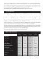
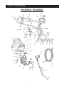
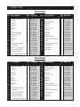
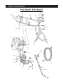
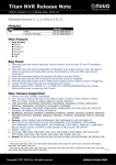
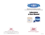
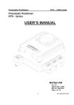
POWERWASHER
Models:
PLS130AH / PLS200AH / DLS200AL / PLS160AH
OPERATING & MAINTENANCE
INSTRUCTIONS
05/11
CONTENTS
Guarantee .................................................................................. 3
Specifications ............................................................................. 3
Safety Precautions ..................................................................... 4
Features ....................................................................................... 4
Assembly and Preparation for Use ........................................... 5
Operation .................................................................................... 6
Chemical Cleaning Agents ....................................................... 6
Maintenance .............................................................................. 7
Parts and Service Contacts ....................................................... 7
Parts Lists and Diagrams ............................................................. 8 - 11
© Copyright CLARKE International. All rights reserved April, 2001
2
Thank you for selecting this CLARKE Power Washer for your cleaning requirements.
This booklet contains important information about its operation and maintenance
and should be read in conjunction with a similar guide produced by the
manufacturers of the engine fitted to this particular unit.
Please read both of these carefully before using the machine.
GUARANTEE
This CLARKE product is guaranteed against faults in manufacture for twelve months
from the date of purchase.
In case it is necessary to make a claim under this scheme, please retain your
receipt or invoice to show when and where your purchase was made.
This guarantee will not be valid if the product is found to have been abused in
anyway, or used otherwise than for its intended purpose.
Under the Terms of this Warranty, any repair or replacement can only be carried
out by Clarke International Limited, or one of our authorised dealers.
Where possible any machine requiring attention should be returned to the dealer
from whom it was purchased. Where this is not appropriate, please contact Clarke
International, Service Department, Tel. 020 8988 7400
This guarantee does not affect your statutory rights.
SPECIFICATIONS
PLS130AH
PLS160AH
PLS200AH
DLS200AL
Honda
Honda
Honda
Lombardini
Engine Rating
5.5HP
6.5HP
11HP
8.5HP
Engine Speed
3,400RPM
3,400RPM
3,400RPM
3,400RPM
Max. Pressure
120Bar
150Bar
200Bar
200Bar
Max. Water flow
11LPM
11LPM
15 LPM
15LPM
500C
500C
500C
500C
SAE20W/40
SAE20W/40
SAE20W/40
SAE20W/40
Measured Sound Power
101 dB
100 dB
103 dB
109 dB
Guaranteed Sound Power
103 dB
102 dB
106dB
109 dB
30PSI
30PSI
30PSI
30PSI
7330260
7330280
7330300
7330320
Engine Type
Max. Water temperature
Pump Oil Type
Tyre Pressure
Part No.
3
GENERAL SAFETY PRECAUTIONS
WARNING:
Water at high pressure can be dangerous and can cause damage to persons or
property if the operator is careless. Never allow anyone to operate this equipment
unless they are thoroughly reliable, and familiar with the safety precautions.
•
•
•
•
•
•
•
•
NEVER direct the spray towards any person or animal.
•
When making a connection directly to the water mains supply you must ensure
that it incorporates a device suitable to prevent liquids syphoning back from
the power washer into the mains pipework.
•
After the engine has been stopped and the water supply turned off, but before
disconnecting any hose or accessory, ALWAYS release any residual pressure
in the system by operating the trigger.
•
•
ALWAYS keep the machine itself dry and well clear of water spray.
•
When using the chemical injection facility, use only the chemical cleaning agents
(detergents) that are approved for power washers. CLARKE Traffic Film Remover or
CLARKE Wash and WAX (available from your dealer), is recommended.
NEVER direct the spray towards electrical wiring or equipment.
NEVER hold your finger over the high pressure nozzle.
NEVER allow children to use this machine.
NEVER operate the machine with any of the covers removed.
NEVER attempt any repairs to this machine unless you are properly qualified.
NEVER supply any liquid other than water to the water inlet.
NEVER use the chemical injection facility to introduce solvents, e.g. paint
thinners, petrol, oil etc.
When not in use, ALWAYS disconnect from the water supply, and ensure the
system is completely drained. Store in a cool dry location.
FEATURES
These fully portable machines incorporate a variable pressure control, together
with a fan or jet spray, and may be used with or without a detergent. Although
these machines were designed to operate using a mains water supply, they will
also work satisfactorily with a supply which is under positive pressure, i.e. from an
elevated water tank etc.
IMPORTANT:
When using the mains water supply, you must ensure you comply
with all local bye laws.
4
ASSEMBLY and PREPARATION FOR USE.
A - Pressure Regulator Knob
B - Low Pressure Water Inlet
C - High Pressure Water Outlet
D - Pressure Gauge
E - Unloader Valve
F - Detergent Hose
1. Attach the handle to the frame, using the plastic screws supplied.
2. Assemble the lance, by screwing the two halves together securely, with the
hand grip in any position convenient to the operator.
3. Two nipple sizes are supplied. That with the larger bore, is the low pressure
nipple, and should be screwed in to the tube nearest to the hand grip, using a
suitable socket.
The smaller bore nipple, is therefore screwed into the tube furthest from the
hand grip.
4. Connect one end of the high pressure hose to the upper connection on the
unloader valve, and the other end to the connection at the lance, ensuring
the seals are correctly in place.
The hose from the mains supply is connected to the lower connection, as
shown in fig 1.
A good quality hose of at least 1/2” should be used, and is available from DIY,
hardware and gardening supply stores.
ALL connections must be tight to avoid leaks.
5. Check the pump oil level using the sight glass, but be aware that if the level is
not visible, it may be as a result of over-filling, and should be checked by
removing the filler plug, and checking. Top up where necessary with the
recommended oil.
6. Refer to the handbook supplied for the engine, and check the engine oil level,
topping up where necessary with the recommended oil.
5
OPERATION
1. Turn the water supply fully ON at the mains.
2. Refer to the engine handbook, and start the engine. Move the speed lever to
MAX.
3. To set the lance at high pressure, turn the hand grip of the
lance clockwise (i.e. screw it ‘IN’), as far as it will go.
Low pressure is set by screwing the grip ‘OUT.
NOTE: Low pressure setting is used for
detergent spraying.
4. Check that there are no leaks
in the line connections. Switch
off the engine and make the
necessary repairs before restarting the engine and pressing the trigger of the lance.
5. With the lance set at high pressure, (i.e. the hand grip screwed ‘in’), the pressure
may be regulated by turning the adjuster knob on the unloader valve.
6. The low pressure setting is used for detergent pick-up (see below).
ALWAYS ensure the filter is attached to the end of the pick-up tube, and is
completely submerged in the detergent. It is not necessary to adjust the
pressure at the unloader valve when set to low pressure.
NOTE:
1. If there is any difficulty in starting the engine, particularly the diesel model, get
an assistant to fully depress the lance trigger whilst you attempt to start. This
will relieve any pressure in the pump so that there is no load on the engine,
making for an easier start.
2. Be aware that the pump delivers a considerable pressure. If the lance is set to
high pressure and the trigger is depressed, you will experience a kick back.
Ensure you are prepared for this, and hold the lance firmly. DO NOT allow
children to hold or operate the lance.
CHEMICAL CLEANING AGENTS
To improve cleaning qualities, chemical cleaning agents (detergents) may be
injected into the low pressure spray. This is particularly useful for washing cars,
greasy engine parts, oil spots on concrete etc.
To inject a detergent, insert the clear plastic hose with filter attachment into the
detergent container, ensuring it is completely submerged.
NOTE: Use ONLY detergents designed for use with power washers. We recommend
the use of CLARKE Traffic Film Remover, which is a powerful low foaming agent, for
car cleaning, as well as other cleaning tasks.
When detergent injection is required, screw the lance hand grip out (anticlockwise),
to the low pressure setting, and the detergent will automatically be drawn into the
6
water supply.
Spray the detergent on to the vehicle, patio etc, and allow it to work itself into the
grime.
To rinse, set the lance to it’s high pressure setting, and blast off the off the dirt.
After cleaning, suspend the detergent hose in a container of clean water. Set the
lance to low pressure, and with the engine running, and the mains water supply
‘on’, depress the trigger of the lance, and thoroughly flush out the system.
MAINTENANCE
If detergents have been used, it is important to flush the system with clean
water for a few minutes after use.
If there is a danger of freezing, anti freeze should be mixed with the flush water,
or the system must be completely drained.
After the final flush, stop the engine; do not allow it to idle for longer than 15
seconds.
Storage
Store in an upright position, completely drained of water, in a dry location.
Engine
Refer to the engine handbook and service accordingly.
NOTE: Engine oil should be checked regularly.
Pump
Change the oil after the first 50 hours of service and every 500 hours thereafter.
Check the level as described on page 3.
DO NOT attempt to carry out any mechanical repairs yourself. Please contact
your CLARKE dealer for servicing and repairs.
PARTS & SERVICE CONTACTS
For Spare Parts and Service, please contact your nearest dealer,
or CLARKE International, on one of the following numbers.
PARTS & SERVICE TEL: 020 8988 7400
PARTS & SERVICE FAX: 020 8558 3622
or e-mail as follows:
PARTS: [email protected]
SERVICE: [email protected]
7
PARTS LIST
PLS200AH & DLS200AL
No. Description
Qty
Part No.
No. Description
Qty
Part No.
1
Engine (200AH) 11HP 1
8000081
17
Washer M8
4
3044582
1
Engine (200AL) 11HP
1
8000805
18
Washer M8
4
3044582
2
Pump
1
AR20001
19
Screw M8
4
3044506
3
Frame
1
8050490
20
Engine Bracket
2
8050700
4
Screw
4
3040526
21
Anti Vibration Mount
4
8950357
5
Washer
4
3040583
22
Nut M8
2
3040611
6
Key
1
3040481
23
Washer M8
2
3044576
7
Screw (200AB)
4
3044508
24
Saddle
2
2100308
Screw (200AH)
4
3044509
25
Feet
2
2100313
Screw (200AL)
4
3044518
26
Screw
2
3044508
Washer M8 (200AB)
4
3044576
27
Plastic Insert
2
2000337
Washer M10 (200AH) 4
3044577
28
Screw
2
3044544
Washer M10 (200AL)
4
3044577
29
Washer
2
1301402
Washer M8 (200AB)
4
3044576
30
Knob M6x40
2
7200326
Washer M10 (200AH) 4
3044577
31
Label (Spec.)
1
8950880
Washer M10 (200AL)
4
3044577
32
Label (POWERWASH)
1
8950885
Nut M8 (200AB)
4
3040611
33
Hose
1
AR13004
Nut M10 (200AH)
4
3040612
34
Lance Handle Assy
1
AW010431806
Nut M10 (200AL)
4
3040612
35
Twin Lance
1
AW004392403
11
Pressure Gauge
1
AR13003
36
Nozzle HP
1
AW004180210
12
Unloader
1
AR13007
37
Nozzle LP
1
AW004180221
13
Hose Connection
1
AR15504
38
Wheel 260x20
2
2100280
14
Chemical Hose
1
AR15502
39
Washer
2
3044583
15
Chemical Filter
1
AR15503
40
Split Pin
2
2200302
16
Screw M8x12
4
3044506
8
9
10
8
PARTS DIAGRAM
PLS200AH, DLS200AL
9
PARTS LIST
PLS130AH
No. Description
1
2
3
4
5
6
7
8
9
10
11
12
13
14
15
16
Engine (130AH)
Pump
Frame
Screw
Washer
Key
Screw (130AB)
Screw (130AH)
Washer
Washer
Nut
Pressure Gauge
Unloader
Hose Connection
Chemical Hose
Chemical Filter
Anti Vibration Mount
Qty Part No.
1
1
1
4
4
1
4
4
4
4
4
1
1
1
1
1
4
No. Description
8000113
AR13001
8050480
3040490
3044576
3040483
3044504
3044503
3044582
3044582
3044506
AR13009
AR13005
AR15504
AR15502
AR15503
8950357
17
18
19
20
21
22
23
24
25
26
27
28
29
30
31
Plastic Foot
Knob M6x40
Washer
Screw
Plastic Insert
Wheel
Washer
Split Pin
Label (Spec.)
Label (POWERWASH)
Hose
Lance Handle Assy
Twin Lance
Nozzle HP
Nozzle LP
Qty Part No.
2
2
2
2
2
2
2
2
1
1
1
1
1
1
1
2100302
7200362
1301402
3040543
2000337
2100280
3044573
2200302
8950880
8950885
AR13004
AW010431806
AW004392403
AW004280209
AW004180221
PLS160AH
No. Description
1
2
3
4
5
6
7
8
9
10
11
12
13
14
15
16
Engine (160AH)
Pump
Frame
Screw
Washer
Key
Screw
Washer
Washer
Nut
Pressure Gauge
Unloader
Hose Connection
Chemical Hose
Chemical Filter
Anti Vibration Mount
Qty Part No.
1
1
1
4
4
1
4
4
4
4
1
1
1
1
1
4
No. Description
8000055
AR16001
8050480
3040490
3044576
3040483
3044503
3044582
3044582
3044506
AR13009
AR13006
AR15504
AR15502
AR15509
8950357
17
18
19
20
21
22
23
24
25
26
27
28
29
30
31
10
Plastic Foot
Knob M6x40
Washer
Screw
Plastic Insert
Wheel
Washer
Split Pin
Label (Spec.)
Label (POWERWASH)
Hose
Lance Handle Assy
Twin Lance
Nozzle HP
Nozzle LP
Qty Part No.
2
2
2
2
2
2
2
2
1
1
1
1
1
1
1
2100302
7200362
1301402
3040543
2000337
2100280
3044583
2200302
8950880
8950885
AR13004
AW010431806
AW004392403
AW004180208
AW004180221
PARTS DIAGRAM
PLS130AH, PLS160AH
11