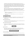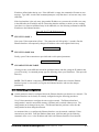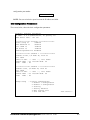
1
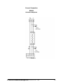
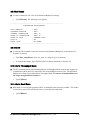
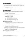
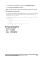
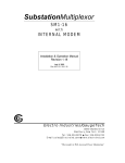
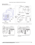
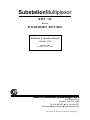
SubstationMultiplexor
SM1-16
with
ETHERNET OPTION
Installation & Operation Manual
Version 1.04
August 11, 2006
Doc # E113-7-07 V1.04
e
Electro Industries/GaugeTech
1800 Shames Drive
Westbury, New York 11590
Tel: 516-334-0870 Fax: 516-338-4741
E-mail:[email protected] www.electroind.com
“The Leader in Web Accessed Power Monitoring ”
Substation Multiplexor SM1-16
with Ethernet Option
User Manual
Revision 1.04
Published by:
Electro Industries/GaugeTech
1800 Shames Drive
Westbury, NY 11590
All rights reserved. No part of this
publication may be reproduced or
transmitted in any form or by any
means, electronic or mechanical,
including photocopying, recording,
or information storage or retrieval
systems or any future forms of
duplication, for any purpose other
than the purchaser’s use, without the
expressed written permission of
Electro Industries/GaugeTech.
© 2006
Electro Industries/GaugeTech
Printed in the United States of
America.
e Electro Industries/GaugeTech
Doc # E113-7-07 V1.04
i
Customer Service and Support
Customer support is available 9:00 am to 4:30 pm, eastern standard time, Monday through Friday.
Please have the model, serial number and a detailed problem description available. If the problem
concerns a particular reading, please have all meter readings available. When returning any merchandise
to EIG, a return authorization number is required. For customer or technical assistance, repair or
calibration, phone 516-334-0870 or fax 516-338-4741.
Product Warranty
Electro Industries/GaugeTech warrants all products to be free from defects in material and workmanship
for a period of four years from the date of shipment. During the warranty period, we will, at our option,
either repair or replace any product that proves to be defective.
To exercise this warranty, fax or call our customer-service department. You will receive prompt
assistance and return instructions. Send the instrument, transportation prepaid, to EIG at 1800 Shames
Drive, Westbury, NY 11590. Repairs will be made and the instrument will be returned.
Limitation of Warranty
This warranty does not apply to defects resulting from unauthorized modification, misuse, or use for any
reason other than electrical power monitoring.
OUR PRODUCTS ARE NOT TO BE USED FOR PRIMARY OVER-CURRENT
PROTECTION. ANY PROTECTION FEATURE IN OUR PRODUCTS IS TO BE USED FOR
ALARM OR SECONDARY PROTECTION ONLY.
THIS WARRANTY IS IN LIEU OF ALL OTHER WARRANTIES, EXPRESSED OR
IMPLIED, INCLUDING ANY IMPLIED WARRANTY OF MERCHANTABILITY OR
FITNESS FOR A PARTICULAR PURPOSE. ELECTRO INDUSTRIES/GAUGETECH
SHALL NOT BE LIABLE FOR ANY INDIRECT, SPECIAL OR CONSEQUENTIAL
DAMAGES ARISING FROM ANY AUTHORIZED OR UNAUTHORIZED USE OF ANY
ELECTRO INDUSTRIES/GAUGETECH PRODUCT. LIABILITY SHALL BE LIMITED TO
THE ORIGINAL COST OF THE PRODUCT SOLD.
Statement of Calibration
Our instruments are inspected and tested in accordance with specifications published by Electro
Industries/GaugeTech. The accuracy and a calibration of our instruments are traceable to the National
Institute of Standards and Technology through equipment that is calibrated at planned intervals by
comparison to certified standards.
Disclaimer
The information presented in this publication has been carefully checked for reliability; however, no
responsibility is assumed for inaccuracies. The information contained in this document is subject to
change without notice.
e Electro Industries/GaugeTech
Doc # E113-7-07 V1.04
ii
About Electro Industries/GaugeTech
Electro Industries/GaugeTech was founded in 1973 by Dr. Samuel Kagan. Dr. Kagan’s first innovation,
an affordable, easy-to-use AC power meter, revolutionized the power-monitoring field. In the 1980s Dr.
Kagan and his team at EIG developed a digital multifunction monitor capable of measuring every aspect
of power. EIG further transformed AC power metering and power distribution with the Futura+ device,
which supplies all the functionality of a fault recorder, an event recorder and a data logger in one single
meter. Today, with the Nexus 1250/1252, 1260/1262, 1270/1272, Total Web Solutions and a wide variety
of dependable solutions, EIG is a leader in the development and production of power-monitoring
products. All EIG products are designed, manufactured, tested and calibrated at our facility in Westbury,
New York.
EIG Product Applications
Q
Q
Q
Q
Q
Multifunction power monitoring
Single and multifunction power monitoring
Power-quality monitoring
Onboard data logging for trending power usage and quality
Disturbance analysis
Nexus 1250/1252
Q
Q
Q
Q
0.04% Watt-hour Accuracy
Expandable I/O and Trending
Demand Integration Intervals
Harmonics to the 127th Order
Futura+ Series
Q
Q
Q
Q
Power-quality monitoring
High-accuracy AC metering
Onboard data logging
Onboard fault and voltage recording
DM Series
Q
Q
Q
Q
Three-phase multifunction monitoring
Wattage, VAR and amperage
Modbus, Modbus Plus, DNP 3.0 and Ethernet protocols
Analog retransmit signals (0–1 and 4–20mA)
Single-Function Meters
Q
Q
Q
Q
Q
AC voltage and amperage
DC voltage and amperage
AC wattage
Single-phase monitoring with maximum and minimum demands
Transducer readouts
Portable Analyzers
Q
Q
Power-quality analysis
Energy analysis
e Electro Industries/GaugeTech
Doc # E113-7-07 V1.04
iii
e Electro Industries/GaugeTech
Doc # E113-7-07 V1.04
iv
Table of Contents
Chapter 1: Ethernet Option Installation
1.1: Mounting Information
1.2: Communication Connections
1.3: RS232 Wiring Details
1.4: RS485 Wiring Details
1.5: Communication Overview
1.6: Connecting the Substation Multiplexor Directly to a Computer
1.7: Connecting to the Substation Multiplexor Using the Ethernet
1.8: Technical Specifications
Chapter 2: Ethernet Option Configuration
2.1: Introduction
2.2: Ethernet Module . . . . . . . . . . . . . . . . . . . . . . . . . . . . .
2.3: Ethernet Option Setup . . . . . . . . . . . . . . . . . . . . . . . . . . .
2.4: Default IP Address . . . . . . . . . . . . . . . . . . . . . . . . . . . .
2.5: AutoIP . . . . . . . . . . . . . . . . . . . . . . . . . . . . . . . . .
2.6: Setting the IPAddress . . . . . . . . . . . . . . . . . . . . . . . . . . .
2.7: Networking Configuration . . . . . . . . . . . . . . . . . . . . . . . . .
2.8: Configuration Parameters . . . . . . . . . . . . . . . . . . . . . . . . .
1-1
1-4
1-6
1-7
1-10
1-11
1-11
1-12
2-1
2-1
2-1
2-1
2-1
2-2
2-3
2-4
Chapter 3: Ethernet Option Operation
3.1: Overview . . . . . . . . . . . . . . . . . . . . . . . . . . . . . . . .
3-1
3.2: Alternate Software . . . . . . . . . . . . . . . . . . . . . . . . . . . .
3-2
®
3.3: Using Windows HyperTerminal with the Substation Multiplexor . . . . . . . 3-3
3.4: Using EIG’s Communicator with the Substation Multiplexor . . . . .
3-6
3.5: Command Mode . . . . . . . . . . . . . . . . . . . . . . . . . . . . .
3-8
3.6: Port Program Commands . . . . . . . . . . . . . . . . . . . . . . . . . .
3-9
3.7: Port Status . . . . . . . . . . . . . . . . . . . . . . . . . . . . . . .
3-11
3.8: Unit Status . . . . . . . . . . . . . . . . . . . . . . . . . . . . . . .
3-12
3.9: Site ID . . . . . . . . . . . . . . . . . . . . . . . . . . . . . . . . .
3-12
3.10: Go to Throughput Mode . . . . . . . . . . . . . . . . . . . . . . . . .
3-12
3.11: Go to Boot Mode . . . . . . . . . . . . . . . . . . . . . . . . . . . .
3-12
3.12: Go to Mode Selection . . . . . . . . . . . . . . . . . . . . . . . . . .
3-13
3.13: Password Protection . . . . . . . . . . . . . . . . . . . . . . . . . . .
3-13
3.14: Contact Information for EIG . . . . . . . . . . . . . . . . . . . . . . .
3-14
e Electro Industries/GaugeTech
Doc # E113-7-07 V1.04
v
e Electro Industries/GaugeTech
Doc # E113-7-07 V1.04
vi
Chapter 1
Ethernet Option Installation
1.1: Mounting Information
Q
The Substation Multiplexor with Ethernet Option is designed to mount in a standard, 19-inch panel
rack. Mounting for all Substation Multiplexors is the same, regardless of option selection. Use a #10
screw in each of the four slots on the flange to ensure that the unit is installed securely.
Top Vie w
e Electro Industries/GaugeTech
Doc # E113-7-07 V1.04
1-1
Front View
e Electro Industries/GaugeTech
Doc # E113-7-07 V1.04
1-2
Side View
e Electro Industries/GaugeTech
Doc # E113-7-07 V1.04
1-3
e Electro Industries/GaugeTech
Doc # E113-7-07 V1.04
1
2
NETWORK
S-+ S-+
4
5
6
9
11
12
13
14
The maximum baud rate for all Slave Ports is 57600.
The baud rate for a Master Port is 57600.
•
•
Slave Ports 3–16
9-pin female RS232 ports.
Use a standard RS232 cable.
RS232 SLAVE PORTS
DTE
10
All Slave Ports are factory-set to operate at 9600 baud and
the Master Ports are factory-set to operate at 57600 baud.
MAC Address
8
•
Slave Ports 1 & 2
2-wire RS485
7
When connecting directly to a computer from the RS232
Master Port, set to 232 (DCE).
232(DCE) Network Switch for Master Port
When using Ethernet, set to Network.
RS232 SLAVE PORTS
3
Master Port for Ethernet
Standard RJ45. Set the
232(DCE) Network Switch
to Network when using
Ethernet.
RJ 45
232(DCE)
MASTER
PORT
Master Port RS232
For direct connection to a
computer.
15
POWER
Power Supply
Relay (Detail)
16
Com
N.O.
N.C.
Back Panel
1.2: Communication Connections
1-4
e Electro Industries/GaugeTech
Doc # E113-7-07 V1.04
1-5
Power Indicator
Network Link LED
RxD/TxD/RTS LEDs
RxD/TxD LEDs illuminate when the
unit is Receiving or Transmitting Data.
Slave Port LEDs
Shows which Slave Port the Multiplexor is programmed to use.
Front Panel
1.3: RS232 Wiring Details
Q
RS232 communication is capable for a distance up to 50 feet (15.2 m). The Master Port and Slave
Ports 3–16 are 9-pin female RS232 ports. Use standard RS232 extension cables for all RS232
connections.
Q
The RS232 Master Port enables the Substation Multiplexor to communicate directly with a computer
or over a network. The Master Port is DCE or Network selectable. Set the switch beneath the port to:
•
Network when using the Substation Multiplexor over a network..
•
DCE when connecting the Substation Multiplexor directly to a computer.
RS232 Female Port
RS232 Master Port
Pin Assignments
PIN
1
2
3
4
5
6
7
8
9
Q
DCE
DCD
Tx
Rx
DSR
Gnd
DTR
CTS
RTS
Ring
RS232 Slave Port Pin
Assignments
PIN
1
2
3
4
5
6
7
8
9
DTE
N/A
Rx
Tx
DTR
Gnd
DSR
RTS
CTS
N/A
Shorted Internally
Slave Ports 3–16 are DTE configured. When connecting an RS232 Slave Port to another DTE
device, use a Null Modem to reverse the Rx and Tx pins, as shown below:
e Electro Industries/GaugeTech
Doc # E113-7-07 V1.04
1-6
1.4: RS485 Wiring Details
Q
RS485 communication allows multiple devices to communicate on a bus. The Substation
Multiplexor’s Slave Ports 1 and 2 are 2-wire RS485 terminals, capable for a distance of up to 4000
feet (1219 meters).
•
Use a shielded, twisted pair cable, AWG 22 (0.33 square mm) or larger.
•
Establish point-to-point configurations for each device on a RS485 bus: Connect (+) terminals to
(+) terminals; connect (-) terminals to (-) terminals.
•
Protect cables from sources of electrical noise.
•
Avoid both “star” and “tee” connections (see diagrams on the following pages). No more than
two cables should be connected at any one point on an RS485 network, whether the connections
are for devices, converters or terminal strips.
•
Include all segments when calculating the total cable length of a network. If you are not using an
RS485 repeater, the maximum length for cable connecting all devices is 4000 feet (1219 meters).
•
Connect devices using the diagrams on the following pages. A correct connection requires 1/4
watt resistors connected to the (+) and (-) terminals of each device at the end of a straight-line
bus. The line impedance of the cable and the resistor should match. Generally, a 100- or
120-Ohm resistor will work.
e Electro Industries/GaugeTech
Doc # E113-7-07 V1.04
1-7
Correct Connection
RS485
Substation Multiplexor
e Electro Industries/GaugeTech
Doc # E113-7-07 V1.04
1-8
Incorrect Connection: “T”
“Tee” Connection Incorrect!
The three wires connected in a
“T” shape on both the (+) and (-)
terminals will cause interference
problems.
RS485 Port
Incorrect Connection: “Star”
“Star” Connection Incorrect!
The three wires connected in a
“Star” shape on both the (+) and
(-) terminals will cause interference problems.
RS485 Ports
e Electro Industries/GaugeTech
Doc # E113-7-07 V1.04
1-9
1.5: Communication Overview
e Electro Industries/GaugeTech
Doc # E113-7-07 V1.04
1-10
1.6: Connecting the Substation Multiplexor Directly to a Computer
1. Use an RS232 cable to connect the Substation Multiplexor’s Master Port to an available RS232 port
on the computer.
2. Set the 232(DCE)Network switch beneath the Master Port to 232(DCE).
3. The Master Port is factory-set to operate at 57600 baud. To configure and communicate with the
Substation Multiplexor, run a standard terminal program on the computer, such as Windows
HyperTerminal. See Chapter 3 for details.
1.7: Connecting to the Substation Multiplexor Using the Ethernet.
1. Connect an RJ-45 cable to the Substation Multiplexor’s RJ-45 jack.
2. Set the 232(DCE) Network switch beneath the Master Port to Network.
®
3. Use a standard terminal program on the computer, such as Windows HyperTerminal, to connect to
the Substation Multiplexor and configure it. See Chapter 3 for details.
4. The Ethernet Port is factory-set to operate at 57600 baud. You should keep the port set to 57600 after
you have connected.
e Electro Industries/GaugeTech
Doc # E113-7-07 V1.04
1-11
1.8: Technical Specifications
Interface
RS232 & RS485
Network
Asynchronous 8 data bits, no parity, 1 stop bit
RJ-45 (10BASE-T)
Connectors
Slave Ports 1 & 2
Slave Ports 3–16
Master Port
Ethernet Port
Half-duplex RS485
DB-9F DTE type RS232
RS232/DCE type
RJ-45 type
Size
3.5” (8.8 cm)H x 19.0” (48.26 cm)W x 8.08” (20.52 cm)D
Weight
12 lbs (5.4kg)
LEDs
Power, Network Link, Data Activity of Slave Ports (RxD, TxD, RTS)
Data Rate
600–57.6k BPS; All standard rates, port specific
Signals Supported
Master Port/Ethernet
Slave Ports (1–16)
TxD, RxD
TxD, Rxd, CTS, RTS
Flow Control
Master Port
Slave Ports (1–16)
None
RTS/CTS or none (port specific)
Reset Time
No Reset, 5 minutes, 10 minutes
Buffer Size
Two 16k buffers
Isolation
1500 Vdc
Control Power Options
Suffix -115A
Suffix -D2
Suffix -D
Suffix -230A
115 Vac +/-20%
125 Vac/dc +/-20%
24–48 Vdc +/-20%
230 Vac +/-20%
Control Power Burden
10VA Maximum
Operating Temperature
-20 to +70°C
Humidity
Up to 95% non-condensing
e Electro Industries/GaugeTech
Doc # E113-7-07 V1.04
1-12
Chapter 2
Ethernet Option Configuration
2.1: Introduction
Q
The Ethernet Option gives the user the capability of integrated network connectivity to multiple
devices over Ethernet. This chapter will give the user an overview of how the Ethernet Option
works. Detailed here are the main components of an Ethernet interface and how they are configured.
2.2: Ethernet Module
Q
The Ethernet connection is made with a small module which is embedded in the meter. This small
but powerful module has an RJ-45 Port and the Network Link LED on the front panel tells you when
the unit is connected to the network and is sending and receiving data. When the unit is active, you
actually hear distinct clicking sounds as the Ethernet module does its job.
2.3: Ethernet Option Setup
Q
This chapter covers the required steps to get the Ethernet Interface on-line and working. There is
only one method used to log into the Ethernet Server and set up the IP address:
•
Q
Network Port Login: make a Telnet connection to the network port (9999).
It is important to consider the following points before logging into and configuring the Ethernet
Interface:
•
The Ethernet Interface's IP address must be configured before a network connection is available.
•
Only one person at a time may be logged into the network port for configuring. This eliminates
the possibility of several people trying to configure the Ethernet Interface simultaneously.
2.4: Default IP Address
Q
The Ethernet Interface ships with a default IP address set to 0.0.0.0, which automatically
enables DHCP within the Ethernet Interface.
Provided a DHCP server exists on the network, it will supply the Ethernet Interface with an IP
address, gateway address and subnet mask when the Ethernet Interface boots up. If no DHCP
server exists, the Ethernet Interface will respond with a diagnostic error: the Network Link LED
blinks five times.
2.5: AutoIP
Q
AutoIP allows an Ethernet Interface to obtain an address in a network that does not have a DHCP
server. Windows 98 and 2000 also support AutoIP.
e Electro Industries/GaugeTech
Doc #: E113-7-07 V1.04
2-1
AutoIP assigns a random valid address to the Ethernet Interface in the range of 169.254.x.1 to
169.254.x.1 where x can be between 0 and 255. This range of IP addresses is not to be used over the
Internet. If the Ethernet Interface has not been configured manually and cannot find a DHCP server,
it automatically chooses an address from the reserved range. The Ethernet Interface then uses the
Address Resolution Protocol (ARP) to send out a request asking if any node is using that address.
If another node is using the same address, the Ethernet Interface assigns another IP address, reboots
and repeats the sequence.
NOTE: AutoIP-enabled Ethernet Interfaces are constantly looking for DHCP servers. If a DHCP
server becomes available on the network, the AutoIP-enabled Ethernet Interface switches to the
DHCP server-provided address and the unit reboots. If the DHCP server exists but denies the
Ethernet Interface an IP address, the Ethernet Interface does not attach to the network, but waits and
retries.
•
AutoIP allows a small network of AutoIP-enabled devices to be set up without any need for a
DHCP server or static IP addresses.
•
AutoIP can be disabled by setting the IP address to 0.0.1.0. The 1 in the third octet is the
disabling factor.
2.6: Setting the IP Address
Q
The Ethernet Interface's IP address must be configured before a network connection is available. If
the IP address was not set automatically via DHCP, set it now using a network and the setup
(configuration) menu.
Q
NETWORK PORT LOGIN
The ARP method is available under UNIX and Windows-based systems. The Ethernet Interface will
set its address from the first directed TCP/IP packet it receives.
Q
CLEARING THE ARP TABLE
Clearing an entry in the ARP table should be performed before and after setting the IP Address that
you will be using. In command prompt, type the following (insert your IP Address). Then press the
Enter key.
arp -d 191.12.3.77
Q
ARP ON UNIX
On a Unix host, create an entry in the host's ARP table using the intended IP address and the
hardware address (or MAC Address) of the Ethernet Interface, which is found on the product label.
The label showing the MAC Address is found on the back panel (see section 1.2).
arp -s 191.12.3.77 00:20:4a:xx:xx:xx
Q
ARP ON WINDOWS
In order for the ARP command to work on Windows, the RP table on the PC must have at least one
e Electro Industries/GaugeTech
Doc #: E113-7-07 V1.04
2-2
IP address defined other than its own. If the ARP table is empty, the command will return an error
message. Type ARP -A at the DOS command prompt to verify that there is at least one entry in the
ARP table.
If the local machine is the only entry, ping another IP address on your network to build a new entry
in the ARP table; the IP address must be a host other than the machine on which you are working.
Once there is at least one additional entry in the ARP table, use the following command to ARP the
IP address to the Ethernet Interface:
arp -s 191.12.3.77 00-20-4a-xx-xx-xx
Q
TELNET TO PORT 1
Now open a Telnet connection to Port 1. The connection will fail quickly (3 seconds). But the
Ethernet Interface will temporarily change its IP address to the one designated in this step.
telnet 191.12.3.77 1
Q
TELNET TO PORT 9999
Finally, open a Telnet connection to port 9999 and set all required parameters.
telnet 191.12.3.77 9999
Q
CLEARING THE ARP TABLE
Clearing an entry in the ARP table should be performed before and after setting the IP Address that
you will be using. In command prompt, type the following (insert your IP Address). Then press the
Enter key.
arp -d 191.12.3.77
NOTE: This IP address is temporary and will revert to the default value when the Ethernet
Interface's power is reset, unless you log into the Ethernet Interface and store the changes
permanently.
2.7: Networking Configuration
Q
Certain parameters must be configured before the Ethernet Interface can function on a network. The
Ethernet Interface can be locally or remotely configured using the following procedures:
Use a Telnet connection to configure the unit over the network. The Ethernet Interface's
configuration is stored in nonvolatile memory (NVRam) and is retained without power. The
configuration can be changed at any time. The Ethernet Interface performs a reset after the
configuration has been changed and stored.
As mentioned above, to configure the Ethernet Interface over the network, establish a Telnet
connection to port 9999. From the Windows Start menu, click Run and type the following
command, where x.x.x.x is the IP address and 9999 is the Ethernet Interface's fixed network
e Electro Industries/GaugeTech
Doc #: E113-7-07 V1.04
2-3
configuration port number.
telnet x.x.x.x 9999
NOTE: Be sure to include a space between the IP address and 9999.
2.8: Configuration Parameters
The screen, below, shows the basic configuration parameters.
Hardware: Ethernet Autodetect
IP addr - 0.0.0.0/DHCP/AutoIP, no gateway set
DHCP device name : not set
***************** Security *****************
Telnet setup is
enabled
TFTP download is
enabled
Port 77FEh is
enabled
Web Server is
enabled
Enhanced password is disabled
***************** Channel 1 *****************
Baudrate 57600, I/F Mode 4C, Flow 00
Port 10001
Remote IP Adr: --- none ---, Port 00000
Connect Mode : C0 Disconn Mode: 00
Flush
Mode : 00
***************** Channel 2 *****************
Baudrate 9600, I/F Mode 4C, Flow 00
Port 10002
Remote IP Adr: --- none ---, Port 00000
Connect Mode : C0 Disconn Mode: 00
Flush
Mode : 00
Change Setup
: 0 Server configuration
1 Channel 1 configuration
2 Channel 2 configuration
6 Security
7 Factory defaults
8 Exit without save
9 Save and exit
e Electro Industries/GaugeTech
Doc #: E113-7-07 V1.04
Your choice ?
2-4
Q
Use ONLY Channel 1 when setting up configuration. Disregard Channel 2.
Q
Make sure the Baud Rate is 57600.
Q
If you happen to change something in the configuration by mistake, choose 7, Factory Defaults
at the bottom of the screen, reconfigure Channel 1 to have 57600 Baud Rate.
Q
To change the IP Address, choose “0”, Server Configuration and type new IP Address (consult
your Network Administrator for the proper IP Address).
Q
After you have made any and all changes required, choose 9, Save and Exit to save changes
and disconnect from Telnet.
Q
BAUD RATE
The Ethernet Interface and attached serial device (SM1-16) must agree on a speed or baud rate used
for the serial connection. For the Substation Multiplexor, default settings are 57600 baud rate, 8
data, 1 stop, no parity.
e Electro Industries/GaugeTech
Doc #: E113-7-07 V1.04
2-5
e Electro Industries/GaugeTech
Doc #: E113-7-07 V1.04
2-6
Chapter 3
Ethernet Option Operation
3.1: Overview
Q
Substation Multiplexor with the Ethernet Option provides a dependable solution for substation
telecommunication applications. This unit multiplexes 16 serial ports to one master port, providing
the ability to communicate and switch between multiple serial devices. This option of the Substation
Multiplexor uses Ethernet Technology that allows integrated network connectivity through RJ-45
(10BASE-T) connection.
Substation Multiplexor works with any standard terminal program. Use Windows® HyperTerminal
(Section 3.3), Nexus Communicator or Communicator EXT (Section 3.4) or other communication
software (Section 3.2) to configure the Substation Multiplexor.
Q
Q
Substation Multiplexor has three operating modes:
•
Command Mode (Sections 3.5–3.10)
In Command Mode, the Substation Multiplexor will accept commands from a computer. The unit
is set to put itself in Command Mode upon Power-up, Reset and Auto Refresh (see Section 3.5).
Use Command Mode to configure the Multiplexor and/or check its status. Put the unit in
Throughput Mode to establish communication with the devices connected to the Slave Ports.
•
Throughput Mode (Sections 3.6, 3.10)
In Throughput Mode, Substation Multiplexor transfers data between the computer connected to
its Master/Ethernet Port and the device(s) connected to a selected Slave Port. The Substation
Multiplexor will not accept any commands while in Throughput Mode. To enter Command
Mode from Throughput Mode, send the escape string detailed in Section 3.5.
•
Boot Mode
Boot Mode is used for flash upgrading only as additional features become available. Boot Mode
is not covered in this manual.
New Features of the Substation Multiplexor:
•
Line Feed: Version E01 will respond with Line Feed (LF) at the end of a message. So, if you
are using HyperTerminal, DO NOT check “Append line feeds to incoming line ends”.
•
Default Start-up Slave Port: Select Port for Start-up and Reset (Section 3.6).
•
Choice of Start-up Mode: Select Command or Throughput Mode for Start-up (Section 3.12).
•
Password Protection: Password Protection for Command and Throughput Modes (Section
3.13).
•
Unit Status: Settings and Status displayed (Section 3.8).
e Electro Industries/GaugeTech
Doc # E113-7-07 V1.04
3-1
•
Power On and Off Switch: With this switch, you can shut down without unplugging the unit.
3.2: Alternate Software
Some communication software does not support the Ethernet connection. The software enables the
PC to use one of its Com Ports virtually for the Ethernet connection.
Lantronix offers a free version that enables the virtual com port. You may get the latest version
from their web site.
File: Lantronix_Port_Redirector_V.1.2.6(32-bit).exe
Tested on: Windows® 98 system.
Install this software into your PC by double clicking the file. You may need to restart your PC after
the installation.
Q
Com Setup Steps
1. Open the redirector software Start/Programs/Lantronix Redirector/Configuration.
RDCfg window will open.
2. Click on the Com Setup.
3. Choose the port that will be redirected. Choose Com3 or Com4 if you are using with Hyper
Terminal.
4. Click OK.
5. Click on Add IP.
6. Write IP address at the Host box (xxx.xxx.xxx.xxx)
For TCP Port number, only 3000 ~ 3009 are available. This is fixed. The port number on the
Network Card in SM1-16 should be 11000 higher. If you want to use redirector software, you
have to program the port number between 14000 ~ 14009 when you configure the parameters
with telnet.
7. If the configured Port number is 14001 on the SM1-16, type 3001 on the TCP Port number.
Click OK. Click on Save and Close.
Now Your PC is ready for redirector software.
NOTE: When you connect with Hyper Terminal, make sure to choose the Com Port, which is
redirected by Redirector Software. The redirector software is not necessary for the Nexus
Communicator or Communicator EXT.
e Electro Industries/GaugeTech
Doc # E113-7-07 V1.04
3-2
3.3: Using Windows® HyperTerminal with the Substation Multiplexor
Q
Windows® HyperTerminal is just one type of communications program you may use to configure the
Substation Multiplexor.
1. Refer to Chapter 1 for installation and communication instructions. Be sure to set the Master Port
Switch to 232.
2. From the Windows® Start Menu, select Programs, Accessories, Communications, HyperTerminal.
3. Double-click on the HYPERTRM.exe icon. The following screen appears:
4. Type a name for the location, such as “Multiplexor”, and choose an icon. This saves the connection
information for future use. Click OK. The following screen appears:
e Electro Industries/GaugeTech
Doc # E113-7-07 V1.04
3-3
5. Make a selection from the “Connect Using” menu. Different screens will appear, depending on your
selection. All of the screens will take you to the Multiplexor Properties and ASCII Setup screens:
To make a direct connection to the Substation Multiplexor’s Master Port from the computer:
Select Direct to Comx from the “Connect using” pull-down menu, where x is the computer’s com
port or choose the Com Port redirected by Redirect Software. Click OK. The Comx Properties screen
appears:
Select 57600 from the Bits per Second pull-down menu. (The Substation Multiplexor's Master Port
is factory-set to 57600 baud.) Click the Advanced button to set Receive and Transmit Buffers. Click
OK.
Select Properties from the File Menu on your main screen and click the Settings tab. Skip to step 7.
6. Click OK. The following screen appears.
e Electro Industries/GaugeTech
Doc # E113-7-07 V1.04
3-4
•
Click on the Modify button; click on the Settings tab. The following screen appears.
7. In the “Emulation” field, select ANSI from the pull-down menu.
8. Click on the ASCII Setup button. In the “ASCII Sending” section, click both boxes. In the “ASCII
Receiving” section click all boxes except the “Force incoming data to 7-bit ASCII”. The ASCII
Setup screen should look like the following:
9. Click OK. You are now ready to dial the Substation Multiplexor. Proceed to Section 3.5.
e Electro Industries/GaugeTech
Doc # E113-7-07 V1.04
3-5
3.4: Using EIG’s Nexus Communicator or Communicator EXT
with the Substation Multiplexor
Q
Put the Substation Multiplexor into Command Mode first, so a data string can be recognized by the
Substation Multiplexor. The data string tells the Substation Multiplexor what Slave Port to use and
then instructs it to enter Throughput Mode so data transmission may begin. Be sure to set the
Master Port switch to Network.
Y
Note: Be sure to configure the Nexus 1250 Monitor port connected to the Multiplexor to speak
Modbus ASCII. See the Communicator User Manual for details.
1. Before connecting to Substation Multiplexor, use Communicator’s Connection Manager to edit the
location where the Substation Multiplexor is installed:
2. Click the Use Data Switch String box.
3. In the Data Switch Connect field, type: ,,,%%%,,,<Enter>,,PTnn<Enter>,,, (where nn is the Slave
Port you wish to use).
• ,,,%%%,,, will put the SM1-16 into Command Mode.
• , instructs Nexus Communicator to pause for one second.
• PT is the Select Port and Go to Throughput Mode command (see Section 5.6)
• nn represents the number of the Slave Port to which you wish to connect.
• ,,, instructs Nexus Communicator to pause for three seconds.
4. Add a Nexus Network Device at the bottom. The protocol should be Modbus ASCII with appropriate
Modbus Slave Device Address, IP Address, and Port Number.
5. After the connection is established, use Low Level Access to send other commands to the Substation
Multiplexor while connected. See Section 3.5.
e Electro Industries/GaugeTech
Doc # E113-7-07 V1.04
3-6
To access Low Level Access, click Tools, Low Level Access. The following screen will appear:
Check the Add CR box at the top of the screen. In the box marked CRC Type, click None.
Follow the instructions in Sections 3.5-3.13, to send commands. Below is a typical screen.
NOTE: All boxes should be clear for the Escape String (Section 3.5).
e Electro Industries/GaugeTech
Doc # E113-7-07 V1.04
3-7
3.5: Command Mode
Q
To enter Command Mode from Throughput Mode, send the following escape string:
•
[2-second pause]%%%[2-second pause]
•
After the last 2-second pause, type H[Enter].
Y
Note: This is an actual 2-second pause on either side of the command. The “%” keystrokes must be
made less than two seconds apart.
Q
BE SURE TO USE ALL CAPITAL LETTERS WHEN SENDING COMMANDS TO THE
MULTIPLEXOR; THE UNIT ONLY RECOGNIZES CAPITAL LETTERS.
Q
To begin, type H[Enter]. The following Command Menu appears:
-------------------------------------------EIG SM Command Mode Commands
H
: Display This Menu
HP
: Display Port Program Commands
HS
: Display Port Status
HU
: Display Unit Status
SI
: Program Site ID
GT
: Go to Throughput Mode
GB
: Go to Boot Mode
GM
: Go to Mode Selection
PW
: Password Protection
EIG : Electro Industries
--------------------------------------------
Q
Commands are listed on the left. Type any command and press Enter. Type H[Enter] at anytime to
access this menu. See the following sections for details about each command.
e Electro Industries/GaugeTech
Doc # E113-7-07 V1.04
3-8
3.6: Port Program Commands
Q
Use the Port Program commands to configure parameters of the Substation Multiplexor’s 16 Slave
ports.
Q
To access a list of the Port Program commands, type HP[Enter]. The following menu appears:
-----------------------------------------------------Port Program Commands
PS
: Select Port
PT
: Select Port & Go to Throughput Mode
PD
: Select Start-up Port
PF
: Choose Flow Control
PB
: Choose Baud Rate
PN
: Program Port Name
-----------------------------------------------------Q
Q
Q
PS: Select Port
Use this command to select the Slave Port you wish to use.
•
Type PSnn[Enter], where nn is the two-digit number of the Slave Port (01–16):
•
For example: PS04[Enter] selects Slave Port 4.
•
To begin using the Slave Port you must put the Multiplexor in Throughput Mode with either the
GT command (Section 3.10) or the PT command (see below).
PT: Select Port & Go to Throughput Mode
Use this command to access one of the Substation Multiplexor’s 16 Slave ports and put the unit into
Throughput Mode so data transmission may begin. This command combines the PS and GT
commands.
•
Type PTnn[Enter], where nn is the two-digit number of the Slave Port you wish to access. The
Substation Multiplexor will select this port and then go to Throughput Mode, allowing
communication between the computer and the device connected to the port.
•
For example: PT04[Enter] selects Slave Port 4 and puts the Substation Multiplexor in
Throughput Mode.
PD: Select Start-up Port
Use this command to select a Default Slave Port. When the unit is powered up or reset, the current
slave port connection will go to this default port. Use the HU command to check current default
settings.
•
For example, PD03 would select Port 3 as the default port.
e Electro Industries/GaugeTech
Doc # E113-7-07 V1.04
3-9
Q
PF: Choose Flow Control
The Hardware flow control option is programmable for all RS232 ports (Slave ports 03–16). No
Flow control is the default. Enable Flow Control if a device connected to the Substation Multiplexor
requires it. Select the port first, using the PS command (see above).
•
•
Q
Q
To select Hardware Flow Control type PFH[Enter].
To select No Flow Control type PFN[Enter].
PB: Choose Baud Rate
Use this command to choose a baud rate for the current Slave Port. All 16 ports can be programmed
with baud rates ranging from 600 to 57600. Select the port first, using the PS command (see above).
All ports are factory-set at 9600 baud.
•
Type PBn[Enter], where n is a digit between 1 and 8 inclusive:
1=57600; 2=38400; 3=19200; 4=9600; 5=4800; 6=2400; 7=1200; 8=600.
•
For example: PB4[Enter] sets the current Slave Port to operate at 9600 baud.
•
To confirm these changes,Type HS[Enter] (the Display Port Status command, see Section 3.7).
PN: Program Port Name
Use this command to name a Slave Port. Select the port using the PS command (see above) and
then:
•
Type PNname[Enter], where name is a string of up to 14 characters.
•
For example: PNMeter 5[Enter] labels the current Slave Port as “Meter 5”.
•
To confirm these changes,Type HS[Enter] (the Display Port Status command; see Section 3.7).
e Electro Industries/GaugeTech
Doc # E113-7-07 V1.04
3-10
3.7: Port Status
Q
Use this command to view a list of Slave Port settings.
•
Type HS[Enter]. The following screen appears.
SUBSTATION MULTIPLEXOR PORT STATUS
-----------------------------------------------------No. LINE
FLOW CTRL
BAUD RATE PORT NAME
-----------------------------------------------------01 | RS485 | NONE
|
9600
| DMMS
02 | RS485 | NONE
|
38400
| CPU1000
03 | RS232 | NONE
|
19200
| NA
04 | RS232 | NONE
|
9600
| NA
05 | RS232 | HARDWARE
|
9600
| NA
06 | RS232 | NONE
|
9600
| NA
07 | RS232 | NONE
|
9600
| NA
08 | RS232 | NONE
|
9600
| NA
09 | RS232 | NONE
|
9600
| NA
10 | RS232 | NONE
|
9600
| NA
11 | RS232 | NONE
|
9600
| NA
12 | RS232 | NONE
|
9600
| NA
13 | RS232 | NONE
|
9600
| NA
14 | RS232 | NONE
|
9600
| NA
15 | RS232 | NONE
|
9600
| NA
16 | RS232 | NONE
|
9600
| NEXUS
------------------------------------------------------
e Electro Industries/GaugeTech
Doc # E113-7-07 V1.04
3-11
3.8: Unit Status
Q
Use this command to view a list of all Substation Multiplexor settings.
•
Type HU[Enter]. The following screen appears.
-----------------------------------------------------SUBSTATION MULTIPLEXOR
BOOT VERSION
: E050
SOFTWARE VERSION
: E010
CURRENT CONNECTION
: PORT 01
START-UP CONNECTION
: PORT 02
START-UP MODE
: COMMAND MODE
SITE ID
: NA
RESET TIME
: NO RESET
------------------------------------------------------
3.9: Site ID
Q
Use the Site ID command to name the location of the Substation Multiplexor. A maximum of 14
characters is allowed.
•
Type SIsite_name[Enter], where site_name is a string of up to 14 characters.
•
To confirm this change, Type HU[Enter] (the Unit Status command; see Section 3.8).
3.10: Go to Throughput Mode
Q
The GT command puts the Substation Multiplexor in Throughput Mode, allowing the computer to
communicate with the device(s) connected to the selected Multiplexor Slave Port. The Substation
Multiplexor will not accept commands in Throughput Mode. To return to Command Mode send
the escape string detailed in Section 3.5.
•
Type GT[Enter]
3.11: Go to Boot Mode
Q
Boot Mode is used for flash upgrading ONLY, as additional features become available. This feature
is reserved for use by EIG technicians, unless you are otherwise authorized.
•
Type GB[Enter].
e Electro Industries/GaugeTech
Doc # E113-7-07 V1.04
3-12
3.12: Go to Mode Selection
Q
In previous versions, Substation Multiplexor always started in Command Mode. Now, you can
choose Command or Throughput Mode. The advantage of this new feature: When SM1-16 resets
for any reason, it will be in your mode of choice.
•
•
Type GMC[Enter]for Command Mode.
Type GMT[Enter]for Throughput Mode.
•
To confirm this change, Type HU[Enter] (the Unit Status command; see Section 3.8).
3.13: Password Protection
Q
Password Protection is available for Command Mode and Throughput Mode. Each mode is
protected by its own password and each password is independent from the other.
•
Type PW[Enter]. The following screen appears:
-----------------------------------------------------PASSWORD PROTECTION
COMMAND MODE
: DISABLED
THROUGHPUT MODE : DISABLED
PASSWORD COMMANDS
PWCE : Enable Password for Command Mode
PWCD : Disable Password for Command Mode
PWTE : Enable Password for Throughput Mode
PWTD : Disable Password for Throughput Mode
-----------------------------------------------------Q Command Mode Password Protection
•
Type PWCE[Enter] to enable the password. For this example, 123 will be the password.
•
Type W123[Enter] (W<password>[Enter])
•
Type W123[Enter] again. OK will appear.
•
Type PW[Enter] to verify the enabled Command Mode Password.
Reset the unit or go to Throughput Mode and come back to Command Mode. Type any command; it
will be password protected. Type the password to use all commands.
•
Q
Type W123. OK will appear. All commands are available.
Disable Command Mode Password Protection
•
Type PWCD[Enter]. Write the password you wish to disable (W123).
e Electro Industries/GaugeTech
Doc # E113-7-07 V1.04
3-13
•
If you have typed a wrong password, you will have to type PWCD[Enter] W123 again.
•
If you typed the correct password, OK will appear.
NOTE: To change a password, you must disable the password first. Then, enter a new password.
Q
Throughput Mode Password Protection
The passwords set here only protect the GT and PT commands, which are used when the unit needs
to communicate with the slave ports. When this password is enabled, SM1-16 will start in the
command mode after reset or power up.
Throughput Mode Password Protection uses the same sequence as Command Mode above to Enable
and Disable Passwords.
•
Type PWTE[Enter]and follow the sequence to enable the password.
•
Type PWTD[Enter]and follow the sequence to disable the password.
•
Type PW[Enter] to verify the enabled Throughput Mode Password.
3.14: Contact Information for EIG
Electro Industries/GaugeTech
Telephone: 516-334-0870
Fax:
516-338-4741
e-mail:
[email protected]
website:
www.electroind.com
e Electro Industries/GaugeTech
Doc # E113-7-07 V1.04
3-14