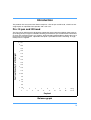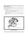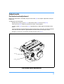
1
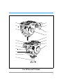
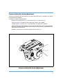
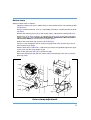
System
Operators Guide
PRO-10
Vinten
Camera Control Solutions
protouch
Pro-10
System
Publication Part No. 3809-8
Issue 2
Copyright © Vinten Broadcast Limited 2005
All rights reserved throughout the world. No part of this document may be stored in a retrieval system, transmitted, copied
or reproduced in any way including, but not limited to, photocopy, photograph, magnetic or other record without the prior
agreement and permission in writing of
Vinten Broadcast Limited.
Vinten is a registered trademark of Vinten Broadcast Limited.
Safety - read this first
Warning Symbols in this Operators Guide
Where there is a risk of personal injury, injury to others, or damage to the pan
and tilt head or associated equipment, comments appear, highlighted by the
word WARNING! and supported by the warning triangle symbol.
Technical data
Pro-10 pan and tilt head
Weight
Head with bowl clamp
Pan bar
2.5 kg (5.5lb)
0.25 kg (0.55 lb)
Height to mounting face
13.8 cm (5.4 in.)
Length
14.4 cm (5.7 in.)
Width
15.8 cm (6.2 in.)
Load capacity
Tilt range
Pan range
Tripod fixing
10 kg (22 lb)
+90° -60°
360°
75 mm ball
Pozi-Loc tripod
Levelling bowl diameter
75 mm
Maximum height with floor spreader
156.2 cm (61.5 in.)
Minimum height with floor spreader
41.6 cm (16.4 in.)
Weight
Transport length
Recommended maximum load
3.2 kg (7.0 lb)
71 cm (28.0 in.)
25 kg (55 lb)
Floor spreader
Maximum leg radius
77 cm (22.5 in.)
Minimum leg radius
38 cm (15 in.)
Weight
0.7 kg (1.5 lb)
3
Further information
For full details on maintenance and spare parts, please refer to protouch Pro-10 System - Maintenance Manual and Illustrated Parts List (Publication Part No. 3809-9) This is obtainable from
Vinten Broadcast Limited or your local Vinten distributor. For information on-line, visit our website
at
www.vinten.com.
4
Contents
Page
Safety - read this first . . . . . . . . . . . . . . . . . . . . . . . . . . . . . . . . . . . . . . . . . . . . . . . . . . . . . . . . 3
Technical data . . . . . . . . . . . . . . . . . . . . . . . . . . . . . . . . . . . . . . . . . . . . . . . . . . . . . . . . . . . . . . 3
Further information. . . . . . . . . . . . . . . . . . . . . . . . . . . . . . . . . . . . . . . . . . . . . . . . . . . . . . . . . . 4
Introduction
Pro-10 pan and tilt head . . . . . . . . . . . . . . . . . . . . . . . . . . . . . . . . . . . . . . . . . . . . . . . . . . . 10
Pozi-Loc tripod . . . . . . . . . . . . . . . . . . . . . . . . . . . . . . . . . . . . . . . . . . . . . . . . . . . . . . . . . . . 11
Floor spreader . . . . . . . . . . . . . . . . . . . . . . . . . . . . . . . . . . . . . . . . . . . . . . . . . . . . . . . . . . . 11
Operation
Assembly
Tripod and spreader . . . . . . . . . . . . . . . . . . . . . . . . . . . . . . . . . . . . . . . . . . . . . . . . . . . . 13
Pan and tilt head. . . . . . . . . . . . . . . . . . . . . . . . . . . . . . . . . . . . . . . . . . . . . . . . . . . . . . . 13
Mounting the camera . . . . . . . . . . . . . . . . . . . . . . . . . . . . . . . . . . . . . . . . . . . . . . . . . . . . . . 13
Pan and tilt brakes . . . . . . . . . . . . . . . . . . . . . . . . . . . . . . . . . . . . . . . . . . . . . . . . . . . . . . . . 14
Pan and tilt drag. . . . . . . . . . . . . . . . . . . . . . . . . . . . . . . . . . . . . . . . . . . . . . . . . . . . . . . . . . 14
Optional equipment
Carrying strap . . . . . . . . . . . . . . . . . . . . . . . . . . . . . . . . . . . . . . . . . . . . . . . . . . . . . . . . . . . 15
'Spread-Loc' mid-level spreader . . . . . . . . . . . . . . . . . . . . . . . . . . . . . . . . . . . . . . . . . . . . . 16
Dollies . . . . . . . . . . . . . . . . . . . . . . . . . . . . . . . . . . . . . . . . . . . . . . . . . . . . . . . . . . . . . . . . . 17
Servicing
General . . . . . . . . . . . . . . . . . . . . . . . . . . . . . . . . . . . . . . . . . . . . . . . . . . . . . . . . . . . . . . . . 18
Cleaning. . . . . . . . . . . . . . . . . . . . . . . . . . . . . . . . . . . . . . . . . . . . . . . . . . . . . . . . . . . . . . . . 18
Routine maintenance. . . . . . . . . . . . . . . . . . . . . . . . . . . . . . . . . . . . . . . . . . . . . . . . . . . . . . 18
Battery replacement . . . . . . . . . . . . . . . . . . . . . . . . . . . . . . . . . . . . . . . . . . . . . . . . . . . . 19
Adjustments
Camera slide plate knob adjustment . . . . . . . . . . . . . . . . . . . . . . . . . . . . . . . . . . . . . . . 21
‘Pozi-Loc’ tripod leg clamp adjustment . . . . . . . . . . . . . . . . . . . . . . . . . . . . . . . . . . . . . . 22
Parts list. . . . . . . . . . . . . . . . . . . . . . . . . . . . . . . . . . . . . . . . . . . . . . . . . . . . . . . . . . . . . . . . . . 24
Associated publications
protouch Pro-10 System - Maintenance Manual
Publication Part No. 3809-9
5
(18)
(1)
(17)
(2)
(16)
(3)
(4)
(5)
(15)
(6)
(14)
(7)
(13)
(8)
(12)
(11)
(10)
(9)
Pro-10 Pan and Tilt Head
6
(1)
3/8 in. camera screw
(2)
Slide lock release
(3)
Pan bar
(4)
Tilt brake
(5)
Locating pin
(6)
3/8 in. camera screw stowage
(7)
Camera slide plate clamp
(8)
Tilt drag control
(9)
Bowl clamp
(10)
Illuminated levelling bubble
(11)
Pan brake
(12)
Pan bar mounting
(13)
Levelling bubble illumination switch
(14)
Camera slide plate
(15)
Camera slide plate bung
(16)
Battery compartment
(17)
Pan drag control
(18)
1/4 in. camera screw
7
(26)
(19)
(25)
(20)
(24)
(23)
(22)
(21)
Pozi-Loc Tripod and Spreader
8
(19)
Tripod bowl
(20)
Clamp knob
(21)
Floor spreader
(22)
Floor spreader adjuster
(23)
Foot securing strap
(24)
Leg tie strap
(25)
Attachment point for optional Spread-Loc mid-level spreader
(26)
Tie down hook
9
Introduction
The protouch Pro-10 system from Vinten comprises a Pro-10 pan and tilt head, a Pozi-Loc twostage tripod, an adjustable floor spreader and a soft case.
Pro-10 pan and tilt head
The Pro-10 pan and tilt head is designed to support the latest professional digital video cameras,
up to 10 kg (22 lb) in weight. It embodies fluid drag assemblies for pan and tilt motions with brakes
on each axis to lock the head in any position. An illuminated levelling bubble is fitted to the rear of
the head and a quick-release, adjustable slide plate is provided for camera mounting. A single
fixed pan bar is supplied.
in. mm
8
200
190
Centre of Gravity (C of G) Height
7
180
170
160
6
150
140
5
130
120
110
4
100
90
80
3
70
60
2
50
4
2
3
6
4
8
5
10
6
12
8
7
14
16
18
9
10 kg
20
2 2 lb
Payload
Balance graph
10
Balance
The balance spring in the Pro-10 pan and tilt head is set for an optimum payload of 7.5 kg (16.5
lb) at a centre of gravity (C of G) height of 12.5 cm (4.9 in.), but the head will support a payload of
up to 10 kg (22 lb). The graph shows the relationship between C of G height and payload for optimum performance.
Pan and tilt drag
Both the pan and tilt mechanisms incorporate fluid drag assemblies to ensure smooth movement
of the camera about these axes and are fitted with control knobs (8) (17) to adjust the drag setting.
Pan and tilt brakes
Brakes (4) (11) on each axis are provided to lock the head in any position
Illuminated levelling bubble
To enable the head to be levelled, an illuminated levelling bubble (10) is fitted to the rear of the
head. When the switch (13) is pressed, the bubble will be illuminated for approximately 15 seconds. The battery for the illuminated bubble is contained in a battery compartment (16).
Camera mounting
The camera is attached to the head by means of a slide plate (14), which is provided with a springloaded locating pin (15) and 1/4 in. (18) and 3/8 in. (1) screws. When not in use the screws are
stowed in the camera mounting platform (6). A clamp (7) is provided to hold the slide plate in position and a lock (2) prevents its inadvertent removal from the head.
Pan bar
Pan bar mounting points (12) are located at the rear of the head, on either side of the camera
mounting platform. The pan bar is attached using a pan bar clamp, with angular adjustment available on the mount serrations. A single fixed pan bar (3) is supplied. A second pan bar may be
fitted.
Pozi-Loc tripod
The Pozi-Loc two-stage tripod has aluminium legs and a 75 mm levelling bowl. It is fitted with the
highly-efficient Pozi-Loc leg clamp, which provides quick set-up and easy adjustment.
An optional ‘Spread-Loc’ mid-level spreader may be used.
Floor spreader
The floor spreader increases rigidity of the tripod. Being flexible, the spreader compensates for
uneven ground, protects floors and carpets and prevents the tripod legs sinking into soft ground.
It should be used at all times.
NOTE:
Always use the spreader where possible as this increases rigidity of the tripod.
Being flexible, the spreader compensates for uneven ground. It can be
removed and a dolly fitted. At the fullest extension of the spreader and with all
legs fully retracted, the tripod can be used at its lowest operating height.
Although the tripod can be set up lower than this without the spreader, it is
NOT recommended as the tripod geometry becomes unstable
11
Each arm is of the spreader is adjustable for length (22) and the tripod feet are secured by rubber
straps (23).
12
Operation
Assembly
If not already done, assemble the system as follows:
Tripod and spreader
Lift the tripod out of the case using the finger holes just below the top clamps.
Release the leg tie strap (24) and spread the legs.
Secure the spreader to the tripod feet with the rubber straps (23).
NOTE:
Once assembled, keep the spreader attached to the tripod
Adjust the operating height by undoing the leg clamps (20) and pulling the tripod up to the desired
height. Adjust the spreader (22) if necessary.
Tighten the clamps (20) until an audible click is heard and the knob is in the horizontal, locked
position.
In adverse conditions secure the tripod using the tie-down hook (26), or suspend a weight from
the hook.
WARNING! Use care when the tripod is fully extended and the floor
spreader is in the closed position, as stability will be reduced.
Pan and tilt head
The Pro-10 pan and tilt head is supplied with a removable 75 mm ball mount. Adaptors are available which enable the head to be installed on tripods or pedestals fitted with other mountings.
These are listed under ‘Optional Accessories’.
To install the head, remove the bowl clamp assembly (9) from the head, position the head on the
tripod and refit the bowl clamp assembly from below. Level the head with the aid of the level bubble (10) and tighten the bowl clamp. The level bubble may be illuminated by pressing the switch
(13). The light will extinguish after approximately 15 seconds.
Mounting the camera
Remove the slide plate (14) from the head by releasing the slide plate clamp (7), pressing the slide
lock release (2) and pulling the plate out to the rear.
Install the required camera fixing screw (1) or (18) in the slide plate and retain with the rubber bung
(15). Stow the unused screw in the appropriate stowage (6) in the platform
Attach the slide plate to the camera or camera mounting plate under the approximate centre of
the camera's weight using the mounting screw and locating pin (5)(if appropriate).
Set the platform level and apply both the pan (11) and tilt brakes (4).
13
Push the slide plate and camera into the track in the platform, ensuring the slide lock release (2)
snaps into position.
Tighten the slide plate clamp (7).
Pan and tilt brakes
Brakes on each axis allow the head to be locked at any chosen position. The operating lever for
the pan brake (11) is at the rear of the head. The tilt brake (4) is operated by a lever on the lefthand side of the head.
To apply the brake, turn the lever fully clockwise. To release the brake, turn the lever counterclockwise.
WARNING! When the brakes are not in use, always turn the levers counterclockwise.
DO NOT use the brakes to supplement drag.
Pan and tilt drag
Both the pan and tilt mechanisms incorporate a fluid drag system to ensure smooth movement of
the camera about these axes.
The tilt drag adjustment knob (8) is on the right -hand side of the head, the pan drag knob (17) is
on the top of the body.
To increase drag, turn the appropriate knob clockwise. To decrease drag, turn the knob counterclockwise.
NOTE:
Reduce drag to a minimum when the head is out of use for long periods.
14
Optional equipment
Carrying strap
A carrying strap (27) is available as an optional accessory and is installed as follows:
On the lower moulding of the leg with the strap, drive in the 'knock-out' (24.1) using a suitable tool. If possible, remove the blank from inside the moulding to prevent subsequent rattle.
(27.1)
(27.2)
(27.3)
(27.4)
(24.1)
(27.5)
(27.6)
(19.1)
(19.2)
(27.1)
(27)
(19)
Carrying strap
15
Push a blind captive nut (27.4) into the hole in the lower moulding.
Using a suitable M5 screw, fully compress the blind captive nut. Remove the M5 screw.
Install a washer (27.3) on the lower strap anchor (27.2) and screw into the captive nut
(27.4). Ensure that the hole in the strap anchor is oriented so that the karabiner (27.1) can
be attached
On the underside of the tripod bowl (19), remove and discard the screw (27.5) securing the
corresponding leg clamp (19.2). Do not remove the washer (19.1).
Position the bowl strap anchor (27.6) on the leg clamp, ensuring it is correctly oriented. Using Loctite 221, secure the bowl strap anchor with the 25 mm M6 screw (27.5) supplied with
the strap. Tighten screw to a torque of 4.5 Nm (40 lbf in.).
Using the karabiners (27.1), clip the strap (27) to the strap anchors and adjust to length.
'Spread-Loc' mid-level spreader
The ‘Spread-Loc’ mid-level spreader (28) is available as an optional accessory. To install the
spreader:
Grip the ends of each spreader arm in turn between thumb and fore-finger and press in the
attachment release buttons (28.1).
Push the arm into the tripod attachment (25) until the release engages.
Fit the carpet feet (29).
To remove the spreader, press in the attachment release buttons (28.1) and free each arm
in turn.
(25)
(28.1)
(28)
(29)
'Spread-Loc' mid-level spreader
16
Dollies
The Pro-10 system may be mounted on a variety of OB and studio dollies, which are listed under
“Optional accessories” on page 16.
17
Servicing
General
Protouch products are robustly made to high engineering standards and little attention is required
to maintain serviceability save regular cleaning. Attention to the following points will ensure a long
and useful service life with minimum need for repair.
Cleaning
During indoor use, the only cleaning required should be a regular wipe over with a lint-free cloth.
Dirt accumulated during storage may be removed using a semi-stiff brush. Particular attention
should be paid to the ball mounting face of the head, the space between the tilting assembly and
the base and the mounting bowl of the tripod.
Use out-of-doors under adverse conditions will require special attention. Salt spray should be
washed off with fresh water at the earliest opportunity. Sand and dirt acts as an abrasive and
should be removed using a semi-stiff brush or vacuum cleaner.
NOTE:
Use only detergent-based cleaners. DO NOT use solvent- or oil-based cleaners,
abrasives or wire brushes to remove accumulations of dirt, as these damage
the protective surfaces.
Routine maintenance
During use, check the following:
Check the illumination of the level bubble. Replace battery if necessary.
Check the effectiveness of the pan brake. Reset as necessary.
Check the effectiveness of the camera slide plate clamp. Reset as necessary.
Check the effectiveness of the tripod leg clamps. Reset as necessary.
Check for ageing and cracking of the rubber foot securing straps on the spreader and renew
if necessary.
No further routine maintenance is required.
18
Battery replacement
The battery illuminates the level bubble (10) when the switch (13) is pressed. The level bubble
remains lit for approximately 15 seconds.
The battery should be replaced yearly or whenever the illumination is considered inadequate.
To replace the battery:
Tilt the head forwards to allow access to the battery cover (16) and apply the tilt brake (4).
Push down on the top of the battery cover (16) and pull forward.
Pull the battery (16.1) out of the battery compartment.
Push the replacement battery into the battery compartment, observing the correct polarity.
Refit the battery cover (16).
Press the switch (13) and ensure that the level bubble (10) is lit for approximately 15 seconds.
(4)
(16)
(16.1)
Battery replacement
19
Adjustments
Pan brake knob adjustment
Because its movement is restricted, the pan brake knob (11) may require adjustment after prolonged use.
To adjust the pan brake knob:
Remove the securing screw (11.1) and pull the knob (11) off the shaft (11.2).
Turn the shaft (11.2) clockwise until the pan brake is fully applied.
Install the knob (11) on the shaft (11.2) approximately at right angles to the body of the
head.
Turn the knob fully counterclockwise and ensure the brake is released. Turn the knob clockwise and ensure the brake is applied before the knob reaches the end of it travel.
Readjust as necessary and secure the knob with the screw (11.1).
(11.1)
(11)
(11.2)
Pan brake knob adjustment
20
Camera slide plate knob adjustment
To prevent interference with the payload, the camera slide plate knob (7) should be at or below
the horizontal when applied.
To adjust the camera slide plate knob:
Remove the securing screw (7.1) and pull the knob (7) off the shaft (7.2).
Turn the shaft (7.2) clockwise until the slide plate clamp is fully applied.
Install the knob (7) on the shaft (7.2) approximately at or below the horizontal.
Turn the knob fully counterclockwise and ensure the slide plate clamp is released before
the stop is reached. Turn the knob clockwise and ensure the clamp is applied before the
knob reaches the horizontal.
Readjust as necessary and secure the knob with the screw (7.1).
(7.2)
(7)
(7.1)
Camera slide plate knob adjustment
21
‘Pozi-Loc’ tripod leg clamp adjustment
Bedding-in occurs with ‘Pozi-Loc’ leg clamps, which may necessitate resetting the clamp. Check
the effectiveness of each leg clamp as follows:
Extend all three tripod legs fully and apply the clamp(s).
Position each leg in turn vertically on a set of weighing scales.
Gradually apply body weight to the leg until either or both clamps begin to slip. Note the
reading on the scales at which this occurs.
A reading of less than 35 kg (77 lb) will necessitate adjustment.
Top clamp
Adjust a top clamp as follows:
Turn the clamp knob (20) to the vertical, ‘off’ position
Remove screw (20.1). Using a suitable peg spanner, back off the threaded insert (20.2) slot
by slot until the leg is free to move under its own weight.
While sliding the leg in and out, gradually tighten the threaded insert (20.2) until the clamp
begins to grip.
If not aligned, back off the threaded insert (20.2) until a slot aligns with the hole for screw
(20.1).
Back off the threaded insert (20.2) a further three slots.
Install screw (20.1) to secure the threaded insert (20.2).
(20)
(20.2)
(20.1)
Top clamp adjustment
22
Bottom clamp
Adjust a bottom clamp as follows:
Tighten the clamp (20) until an audible click is heard and the knob is in the locked position
(POSITION 1).
Using a suitable instrument, such as a flat-bladed screwdriver, carefully remove the knob
cap (20.8).
Remove the retaining screw (20.7) and washer (20.6), and pull off the clamp knob (20).
Examine the shaft (20.3). If there is an identifying groove (20.4) on the shaft, proceed as
follows. Otherwise, consult protouch Pro-10 System - Maintenance Manual (Publication Part No. 3809-9) or contact your local Vinten dealer.
Replace the clamp knob (20) and turn it to POSITION 2.
Using a 2.5 mm hexagonal wrench, slacken the grubscrew (20.5) until the leg is free to
move under its own weight.
With the knob still in POSITION 2, slide the leg in and out and gradually tighten the grubscrew (20.5) until the clamp begins to grip.
Back off the grubscrew (20.5) by a quarter-turn (90°).
Secure the clamp knob (20) with the washer (20.6) and retaining screw (20.7). Refit the
knob cap (20.8).
(20.3)
(20.3)
(20.4)
ITI
O
N
2
(20.5)
PO
S
(20)
(20.6)
(20.7)
90°
POSITION 1
(20.8)
(20)
Bottom clamp adjustment
23
Parts list
The following lists include main assemblies, user-replaceable spare parts and optional accessories. For further information regarding repair or spare parts, please contact Vinten Broadcast Ltd
or your local distributor.
For information on-line, visit our website at
www.vinten.com.
Main assemblies
Head
Pro-10 pan and tilt head
3809-3
Tripod
Two-stage tripod, aluminium legs, 75mm bowl
3819-3
Floor spreader
Floor spreader
3818-3
Carrying case
Soft case for protouch systems
U005-190
User-replaceable spare parts
Pan bar
3219-104
Battery
C550-021
Optional accessories
Mid-level spreader
‘Spread-Loc’ mid-level spreader (complete with feet)
Set of three feet (for use with mid-level spreaders)
3781-3
3378-902SP
Carrying strap
Carrying strap
3425-3P
24
Dollies
PD114 dolly
U005-103
ENG (OB) dolly
3319-3B
ENG (Studio) dolly
3319-3C
ENG (OB) dolly - small
3319-3ST
Tripod and pedestal adaptors
75 mm ball to 100 mm bowl adaptor
U005-159
25