1
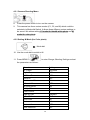
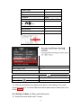
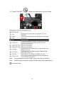
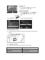
Version: Jun2014/G16 MicroDOC Gel Documentation
System
Instruction Manual
Model Numbers: CSL-MICRODOC
CSL-MICRODOC1D
CSL-MDOCUV312
CSL-MDOCUV3121D
CSL-MDOCUV254
CSL-MDOCUV2541D
CSL-MDOCUV365
CSL-MDOCUV3651D
CSL-MDOCUV254/312
CSL-MDOCUV254/3121D
CSL-MDOCUV254/365
CSL-MDOCUV254/3651D
CSL-MDOCBASIC
CSL-MDOCBASIC1D
www.cleaverscientific.com
[email protected]
Packinglist
MicroDOC (all models except CSL-MDOCBASIC/1D):
-1x Canon PowerShot G16 Digital Camera Package
(Includes all accessories and manuals)
-1x Camera DC Coupler
-1x 4GB Memory Card
-1x Memory Card Reader
-1x Lens Adapter
-1x 8” TFT Colour Screen
-1x Hood
-1x (+3) Close-up Lens
-1x Ethidium Bromide or SYBR Green Filter
-1x Power Cord
-1x US Plug Power Cord for hood and UV transilluminator connection
-1x MicroDOC System Instruction Manual
Product Specification (CSL-MDOCBASIC/1D)
-1x Canon PowerShot G16 Digital Camera Package
(Includes all accessories and manuals)
-1x 4GB Memory Card
-1x Memory Card Reader
-1x Lens Adapter
-1x Hood – manufactured from ebony acrylic
-1x (+3) Close-up Lens
-1x Ethidium Bromide or SYBR Green Filter
Signed by:
Date:
Cleaver Scientific is liable for all missing or damaged parts / accessories
for up to 7 days after customer receipt of this product. Please contact
Cleaver Scientific immediately should this product arrive incomplete or
in an imperfect condition. The manufacturer accepts no responsibility
beyond the 7-day period.
1 Table of Contents
Packing list
………………………………………………………………………1 Table of Contents........................................................................................... 2 Section 1 Warning ................................................................................. 3 Section 2 Introduction ........................................................................... 6 2.1 Overview ..................................................................................................... 6 2.2 Control and Features ................................................................................... 6 2.3 Components guide ...................................................................................... 7 Section 3 Technical Specifications ...................................................... 9 3.1 Camera ........................................................................................................ 9 3.2 Hood ............................................................................................................ 9 Section 4 Installation Instructions ..................................................... 10 4.1 Assemble microDOC System .......................................................................... 10 4.2 Camera Set-Up Menu...................................................................................... 12 4.3 Preparing the Camera ..................................................................................... 13 4.4 Install the UV Transilluminator......................................................................... 15 Section 5 Operation Instructions ....................................................... 34 5.1 DNA Sample Imaging ...................................................................................... 34 5.2 Protein Sample Imaging .................................................................................. 36 5.3 Western Blot .................................................................................................... 36 5.4 Radiographic Film............................................................................................ 36 Section 6 Trouble-shooting guide ...................................................... 37 Section 7 Ordering Information .......................................................... 38 Section 8 Warranty .............................................................................. 39 2 Section1 Warning
Cleaver Scientific’s MicroDOC System has been tested and found to be
compliant with CE regulations. The MicroDOC System is also RoHS compliant
and meets with all environmental directives. These limits of RoHS compliance
were designed to provide reasonable protection against harmful interference
when the equipment is operated in a commercial environment. This equipment
can generate, use, and radiate radio frequency energy, and, if not installed and
used in accordance with the instruction manual, may cause harmful
interference to radio communications. Operation of this equipment in a
residential area may cause harmful interference, in which instance the user will
be required to correct the effects of this interference at their expense. Changes
or modifications not expressly approved by the parties responsible for
compliance could nullify the user’s authority to operate the equipment. It is,
therefore, strongly recommended that the user reads carefully the following
points before operating this equipment.
1.
2.
3.
4.
5.
6.
7.
8.
Read and follow the manual instructions carefully.
Do not alter the equipment. Failure to follow these directions could incur
personal and/or laboratory hazards, as well as invalidate equipment
warranty.
Use a properly grounded electrical outlet with correct voltage and current
handling capacity.
Disconnect the unit from the power supply before maintenance and
servicing. Refer servicing to qualified personnel.
If a solution is accidentally spilt on the instrument, disconnect the
grounded plug and carry out appropriate decontamination measures. For
instance, invert the instrument to prevent solution contacting the internal
components. Remove the bottom cover for inspection of the inner
components or connectors, and replace any damaged parts accordingly.
Never use the equipment in the presence of flammable or combustible
material as fire or explosion may result. This device contains components
which may ignite such material.
Refer maintenance and servicing to qualified personnel.
Ensure that the system is connected to electrical service according to
local and national electrical codes. Failure to comply may cause fire or
3 shock hazard.
9. The unit should only be operated by qualified personnel.
10. It is strongly recommend that the user wears UV protection equipment
when operating the MicroDOC System.
Warning: High Ultraviolet Radiation!
Safety Information
Before connecting to the electrical supply, check the supply voltage is within
the range stated at the rating label, and that the device is earthed. Place the
unit in a safe and dry location. Also follow any safety precautions for chemicals
and/or dangerous materials. If necessary please contact your service
representative or [email protected].
Environmental Conditions
Ensure that the instrument is installed and operated strictly under the following
conditions:
1. Indoor use only
2. ≤95% RH
3. 75 kPa – 106 kPa
4. Altitude must not exceed 2000 metres
5. Ambient to 40°C operating temperature
6. Pollution degree: 2
7. Mains supply voltage fluctuations up to ±10% of the normal voltage
Avoiding Electrical Shock
Follow the guidelines below to ensure safe operation of the unit.
To avoid electrical shock:
1. In the event of accidental liquid spillage, remove the grounded supply cable
from the electrical source and thoroughly dry the contaminated area. It is best
to leave the unit standing for a minimum of 2 hours before further use.
2. NEVER connect or disconnect wire leads from the power jacks when the
power is on.
3. WAIT at least 5 seconds after stopping a run before handling output leads or
connected apparatus.
4. ALWAYS make sure that hands, the work area, and instruments are clean
and dry before connecting or disconnecting the power supply.
4 5. ONLY connect the power supply to a properly grounded AC outlet.
Avoiding Damage to the Instrument
1. Do not attempt to operate the device if it is damaged.
2. Protect this unit from source of physical damage, corrosive agents and
extreme temperatures (direct sunlight etc).
3. To ensure proper ventilation and safety, retain at least 10 cm of space
behind the instrument and at least 5 cm of space on each side.
4. Do not operate the device in high humidity environments (> 95%), or where
condensation may occur.
5. Before applying any cleaning or decontamination methods, other than those
recommended by the manufacturer, users should check with the
manufacturer’s instructions to ensure that the proposed method will not
damage the equipment. E.g. For the microDOC BASIC avoid direct
chemical contact with the plastic as this can cause ‘crazing’, which
compromises the life time of the product. Always use distilled water or a mild
household soap solution for cleaning.
UV Tube Disposal
The UV tubes contain mercury! Please dispose of the tubes in accordance with
local regulations, and handle with care to protect public health and the
environment. For information about recycling, please
see www.lamprecycle.org.
Symbols
The symbols used on the MicroDOC System are explained below:
Indicates an area of potential hazard.
Danger of UV irradiation.
UV radiation causes serious damage to
unprotected eyes and skin. Ensure the all
personnel are properly protected before operation.
Disposal instruction.
DO NOT discard this unit within municipal rubbish at the end of its lifetime.
To maximise protection of the global environment and reduce pollution, please
recycle this unit.
5 Section2 Introduction
2.1 Overview
The Cleaver Scientific MicroDOC is a user-friendly gel documentation system
with 12.1 mega pixel high resolution camera. A large 8” TFT screen enables
images, including agarose and fluorescent gels, colorimetric gels,
autoradiography film and blotting membrane, to be captured in colour, clearly
and easily. The system is computer free and supplied with a 4GB storage card
and 55mm ethidium bromide filter as standard, while an optional SYBR filter is
also available. Files are saved onto the 4GB storage card in RAW, TIFF-RGB
and JPEG formats and may be transferred to computer for analysis with the
highly recommended optional TotalLab™ 1D software.
2.2 Control and Key Features
-
12.1 megapixel digital camera
-
Images viewed in an 8” TFT colour monitor
Light weight compact hood with easy access front panel door panel
Two built-in inner LEDs for epi-illumination
Computer-free image capture
Magnetic safety switch on front door panel
6 2.3 Components guide
Canon PowerShot G16 with Lens Kit
White light power switch
UV light power switch
8” TFT Colour Screen
Door Panel with Safety Switch
Front view
Canon PowerShot G16 with Lens Kit
Camera Video and
power cable
BNC port for thermal printer
Mains Power Socket
Power Socket to Connect Hood
to UV Transilluminator
Rear view
7 MicroDOC Hood Control Panel
1.
– White light power switch
2.
– UV light power switch
3.
– power on indicator
8 Section3 TechnicalSpecifications
3.1 Camera
Camera
Canon PowerShot G16
Effective Pixels
Approx. 12.1 megapixels
CMOS
1/1.7-inch type CMOS; Approx. 12.1 million pixels
Image Resolution
640 x 480 up to 4,000 x 3,000
Lens
6.1 (W) – 30.5 (T) mm (35mm film equivalent: 28
(W) - 140 (T) mm)
F / -Number
f/1.8 (W) - f/2.8 (T)
File Format
Design rule for Camera File system, DPOF
(version 1.1) compliant
Data Type
Still images: Exif 2.3(JPEG), RAW (CR2)
Movies:MOV (Image data: H264 ; Audio data:
Linear PCM (stereo))
Focus-Area Selection
AF mode and manual focus are available
Filter
Ethidium Bromide or SYBR Green (58mm)
Note: Please refer to Canon PowerShot G16 Camera User Guide for detailed
specifications
3.2 Hood (excludes MicroDOC Basic/1D models)
Multi-Power Source
For camera, Inner light lamp, TFT screen
Inner White Light
2x 3W white light LED
Safety Door Switch
Automatically disconnects UV transilluminator,
While opening the chamber door during operation
Monitor
8” TFT liquid crystal screen
Display Format
960 x 234mm
Luminance
350 cd/mm
Display Mode
NTSC / PAL mode switchable
Video and Audio Input
Yes
Chamber Dimension
290 x 220 x 320 mm (W x D x H)
Rated Voltages
110 - 220 Volt
Weight
Approx. 6.1 kg
9 Section4 InstallationInstructions
Cleaver Scientific’s MicroDOC System is factory preinstalled instrument.
Locate the microDOC on a sturdy, level dry surface, and UV transilluminator
before operation. See the assembly procedure below.
4.1 Assemble the MicroDOC System
1. Fix Monitor
2. Connect Cable
3. Press ring release button and
remove the ring
4. Prepare lens adaptor
5. Fix lens adaptor to camera
6. Prepare close up lens
10 7. Fit close-up lens to lens adaptor
8. Prepare EtBr or SYBR Green filter
9. Fit EtBr or SYBR Green filter on top 10. Insert power cable to the camera
adaptor on the chamber
DC coupler
11. Insert camera DC coupler until it
locks, then close the cover
12. Fix camera to the camera adaptor
on the chamber
13. Connect S-video cable to the camera
11 4.2 Camera Set-Up Menu
A)
12 B)
C)
13 4.3 Preparing the Camera
Before installing the camera, please review all function keys in Section 4.2
Camera Set-Up Menu.
Install the DC Coupler as shown below
(Installing the DC Coupler is necessary, because the MicroDOC System
connects to the camera DC coupler, and provides DC power for camera use).
Install the SD card as shown below.
The date and time setting screen will appear when using the camera for the
first time. Set the date and time as shown below:
14 15 4.3.1 Camera Shooting Menu
8.
9.
Press the power button to turn on the camera.
This camera has three custom modes (C1, C2, and M) which could be
selected via Mode dial Switch. It allows three different custom settings to
be saved. We advise setting C1 mode for black& white photo and M
mode for color photo.
4.3.2 Setting M Mode (for Color photo)
Mode dial
10. Use the mode dial to switch to M.
11. Press MENU (
) to enter Change Shooting Settings and set
the parameters as follows:
Menu Item
Setting
AF Frame
FlexiZone
Digital Zoom
OFF
AF-Point Zoom
OFF
Servo AF
OFF
Continuous AF
ON
AF-assist Beam
OFF
MF-point Zoom
ON
Safety MF
ON
Flash Control
---
High ISO NR
Standard
Spot AE Point
AF Point
Wind Filter
Off
Review
3 Sec.
Review Info
OFF
Blink Detection
OFF
16 Custom Disp.
---
Reverse Disp.
ON
IS Mode
Continuous
Converter
NONE
Date Stamp
OFF/Date/Date & Time
Set
---
Func.
Set Shortcut Button
----
Save Setting
C1
Set Shortcut Button
---
Set the movie button…
---
Menu Item
Setting
Auto Power Down
Off
Display Off
3 min.
1.Turn the [
Item
Setting
Shutter Speed
1 sec
]dial to set shutter speed
12. After all parameters have been set as above, save setting to C1 mode
Continue to setup C1 mode for Black and White photo shown below (Don’t turn
off the Camera)
4.3.3 Setting C1 Mode (for Black and White photo)
13. Switch the mode dial to the C1 mode
17 14. Press FUNC.SET(
) Button to change photo color as follows
1
2
Note: It is unnecessary to press FUNC. Key to set color for M Mode
Note: If RAW image is required, please set Recording Pixels parameter to
as shown below:
18 15. Press MENU (
) button to Save Settings to C1
4.3.4 Setting Shutter Speed
16. To adjust the shutter speed, turn the Front Dial located in the front of the
camera
17. Shutter speed ranges from 1/2000 to 15”
18. 2” indicates 2 seconds
19. Longer time means more amount of light, and vice versa
DNA Sample
1” or longer
Protein Sample
1/100, 1/200, 1/300, …
Western Blot
1/10, 1/20, 1/30,
Radiographic Film
1/100, 1/200, 1/300, …
19 4.3.5 Setting Aperture Value
20. Use the Control Dial to adjust
21. Aperture Value is expressed as F-stop (e.g. F2.8). The smaller the F-stop
number, the larger the aperture (lens opening). Aperture Value ranges
from F1.8 to F8.0
DNA Sample
F2.8
Protein Sample
F2.8
Western Blot
F2.8
Radiographic Film
F2.8
4.3.6 Setting Metering Mode
There are three metering modes:
4.3.7 Setting ISO Speed
20 22. ISO value ranges from ISO 80 - 12800, and Auto.
23. Raising ISO value will increase the brightness of the fluorescent signal.
However, the image will get course with increasing ISO value. High ISO
value should be set only for gels with very weak signal.
4.3.8 Adjust the focal frame and focus mode
When zoomed in beyond 5cm-∞ the camera may experience hardship auto
focusing. It is recommended to switch to manual focus mode in these
instances to acquire a better image.
24. Adjust the focal frame accordingly
A.
Press the
B.
Press the
buttons or turn the
dial to specify the general position
C.
Press the
button
*This needs to be done before adjusting and switching to manual focus mode
25. Settings for manual focus mode
A.
Press
21 (the left button on the dial)
B.
choose Manual Focus〈MF〉
C. Preferring to the on-screen MF Indicator
bar and the magnified display area, press
the
buttons or turn the
dial to specify the general focal
position, and then press the
button.
4.4 Sending images to the computer via Wi-Fi
1 Check the computer environment
○
The camera can connect via Wi-Fi to computers running the following
operating systems. For detailed system requirements and compatibility
information, including support in new operating system, please visit the
Canon official website.
22 2 Install CameraWindow on the computer
○
To save images to the computer wirelessly, users must install
CameraWindow, which can be acquired from Service & Support page in
Canon Official Website.
2-1 Download the software
y
y
y
With a computer connected to the internet, and
access http://www.canon.com/icpd/.
Access the site and select the country or region.
Enter “Drivers & Software” page.
Input the camera model name: PowerShot G16
y
Unfold “Software” and download “CameraWindow”.
y
2-2 Begin the installation
y Select the region and country that users live in.
y Select the language.
y Follow the instruction to complete the installation.
23 3 Configure the computer for the Wi-Fi connection (Windows only)
○
y
y
y
Confirm that the computer is connected to the access point.
Configure the setting by clicking the following order: [Start] menu > [All
Programs] > [Canon Utilities] > [CameraWindow] > [Wi-fi connection
setup]
Open the application, then follow the on-screen instructions to
configure the setting.
∗ The following Windows settings are configured when users run the
utility in above steps.
-
Turn on media streaming.
24 This will enable the camera to see/find the computer to
access via Wi-Fi.
-
Turn on network discovery.
This will enable the computer to see/find the camera.
-
Turn on ICMP (Internal Control Message Protocol).
This allows users to check the network connection status.
-
Enable Universal Plug & Play (UPnP).
This will enable network devices to detect each other
automatically.
25 4 Connect via an access point
○
Confirm that the Wi-Fi router or base station conforms to the Wi-fi standards
of PowerShot G16.
Then confirm the following items for network settings.
∗
Connection methods vary depending on whether the access point
supports Wi-Fi Protected Setup (WPS) or not. Refer to the user
manual provided with your access point to check if it supports WPS.
4-1 Connect to WPS-compatible access points
y Confirm that the computer is connected to the access point.
y Access the WiFi menu on the camera.
-
Turn on the camera and press
26 button.
-
Press
button to access the keyboard, and then enter a
nickname. Up to 16characters can be used.
-
Press
buttons or turn the
dial to choose [OK], and
then press
button. Then the Wi-Fi menu is displayed.
-
Choose the target device, and then press
-
To connect to a computer, choose
.
-
Press
dial to choose [Add a
buttons or turn the
Device], and press
-
Press
button.
button.
buttons or turn the
dial to choose [WPS
buttons or turn the
dial to choose [PBC
Connection].
-
Press
Method].
27 ∗
If users choose [PIN Method], a PIN code will be displayed on
the screen. Be sure to set this code in the access point.
Choose a device in the [Select a Device] screen.
-
On the access point, hold down the WPS connection button for a
few seconds.
-
On the camera, press
button. The camera will connect to the
access point.
-
Press
buttons or turn the
computer name, and then press
-
dial to choose the
button.
If the computer is running Windows for the first time, users will
need to install a driver. When the screen at below is displayed on
the camera, click the Start menu on the computer, then click
[Control Panel], and click [Add a device].
28 Double-click the connected camera icon to install the driver. After
driver installation is complete, and the camera and computer
connection is enabled, the AutoPlay screen will be displayed.
Nothing will be displayed on the camera screen.
*If users use Macinstosh computer, please skip this step.
4-2 Connect to access points in the list
y Confirm that the computer is connected to the access point.
y Access the WiFi menu on the camera.
-
Turn on the camera and press
-
Press
button.
button to access the keyboard, and then enter a
nickname. Up to 16characters can be used.
29 -
Press
buttons or turn the
dial to choose [OK], and
then press
button. Then the Wi-Fi menu is displayed.
-
Choose the target device, and then press
-
To connect to a computer, choose
.
-
Press
dial to choose [Add a
buttons or turn the
Device], and press
-
Press
button.
buttons or turn the
(access point), and then press
-
Press
button.
dial to choose a network
button.
button to access the keyboard, and then enter the
password.
30 -
Press
press
-
Press
buttons or turn the
button.
buttons or turn the
computer name, and then press
-
dial to choose [Auto], and
dial to choose the
button.
If the computer is running Windows for the first time, users will
need to install a driver. When the screen at below is displayed on
the camera, click the Start menu on the computer, then click
[Control Panel], and click [Add a device].
Double-click the connected camera icon to install the driver. After
driver installation is complete, and the camera and computer
connection is enabled, the AutoPlay screen will be displayed.
Nothing will be displayed on the camera screen.
*If users use Macinstosh computer, please skip this step.
31 5 Save images to a computer
○
When sending images to a computer, use the computer instead of the
camera.
y
When the camera is connected to the computer, the camera screen is
blank. Display CameraWindow on the computer. *On Macintosh
computer, CameraWindow is automatically displayed when a Wi-Fi
connection is established between the camera and computer.
y
y
*
Click [Import Images from Camera], and then click [Import
Untransferred Images]. Images will be saved to the Pictures folder on
the computer, in separate folders named by date.
Click [OK] in the screen that is displayed after image import is
complete.
For other camera setup requirements, please refer to Canon PowerShot
G16 Camera User Guide.
32 4.5 Install the UV Transilluminator
Caution:
UV transilluminator is a powerful source of UV radiation which will cause
damage to unprotected eyes and skin. Before operating the UV
transilluminator ensure that all personnel in the area are properly protected. It
is preferable that the UV transilluminator is installed and operated in a
darkroom where access and exposure is limited while the unit is in operation.
Each UV transilluminator is equipped with an UV shield. Even though this
shield blocks the ultraviolet radiation emitted by the unit, UV protective
eyewear should also be worn.
1.
Place the hood on the
transilluminator
2.
Connect power cord between
the MicroDOC hood and UV
transilluminator
3.
Plug the three-pronged power
cord into a grounded three-prong
AC outlet of the appropriate
voltage
Note: Step 2 is essential if the safety door switches of the MicroDOC hood are
to control the UV transilluminator. Please follow the installation instructions to
connect the MicroDOC hood and UV transilluminator.
33 Section5 OperationInstructions
The unique feature of the Canon PowerShot G16 is that before capturing an
image, it is possible preview the image from the display while simultaneously
changing the shutter speed, aperture or ISO value.
5.1 DNA Sample Imaging
1.
2.
Turn on the main power and switch on the white light
Turn on the camera
3.
4.
Switch the mode dial to C1 (Black/White photo) mode
Open the Hood door. (The door contains a safety switch, the UV
5.
6.
7.
8.
Transilluminator will automatically shut off when the door is open)
Place gel onto the centre of the UV filter on the transilluminator
Switch off the white light
Close the door
Turn on the UV light source
9.
Adjust Zoom Lever to zoom in and out on image(Section 4.2 Camera
set-up Menu)
10. Change the Shutter Speed (1/2000 - 15”).
For this application, we recommend setting it to 1” or longer.
11. Change the aperture value (F1.8 - 8.0).
For this application, we recommend setting it to F2.8.
12. Change the metering mode (Evaluative, Center Weighted Avg., Spot AE
Point). For this application, we recommend setting it to
Evaluative.
13. Change the ISO value (ISO 80 - 12800 and Auto). For this application,
we recommend using ISO 80 to get the highest Signal to noise ratio
(Factory setting).
14. To set the major focus area on specific bands, press the
34 key
(Section 4.2 B). The AF frame will display in green. Move the AF frame
over the most prominent band by using the control dial.
15. Change the manual focus mode. When zoomed in beyond 5cm-∞ the
camera may experience hardship auto focusing. It is recommended to
switch to manual focus mode〈MF〉(4.3.8 Adjust the focal frame and
focus mode)
16. Focus (Section 4.2 A): Press the shutter button halfway to set focus and
exposure. And then press shutter bottom fully to take the picture.
17. Press
button and then press
to view the pictures on the
memory card full-frame in the monitor (Section 4.2 B). Press
button
again to return to the image shooting mode.
18. Under image viewing mode, press the
the displayed image (Section 4.2 B).
19. Under image viewing mode, press the
button to show the data for
button to delete the displayed
image (Section 4.2 B) if it is not required or unsatisfactory.
Once finished please switch off the Camera, and then turn off UV
Transilluminator and mains power.
20. Remove gel from Hood.
21. Clean the UV transilluminator and dry the filter area with distilled water.
For more detailed information, please consult the instruction manual of UV
transilluminator.
DNA sample imaging example: ISO 80; f/4.5; Shutter speed: 1 Sec.
35 5.2 Protein Sample Imaging
1.
2.
3.
4.
5.
Disconnect the wire cable between hood and UV transilluminator (Please
make sure that the UV transilluminator is OFF).
The hood has two built-in white light LEDs. Use these inner light LEDs as
the light source for this application.
Use the mode dial to switch to M (for colour image)
Keep the aperture set on F2.8, change the Shutter Speed from 1/10, 1/20,
1/30.
Use the DNA sample imaging procedure (Section 5.1 step 9 – 20) for
protein sample image capture.
5.3 Western Blot
1.
2.
3.
4.
5.
Disconnect the wire cable between the hood and UV transilluminator
(Please make sure that the UV transilluminator is OFF).
The hood has two built-in white light LEDs. Use these inner light LEDs as
the light source for this application.
Use the mode dial to switch to M (for colour image).
Keep the aperture set on F2.8, change the Shutter Speed from 1/10, 1/20,
1/30.
Use the DNA sample imaging procedure (Section 5.1 step 9 – 20) for
protein sample image capture.
5.4 Radiographic Film
1.
2.
3.
4.
5.
6.
Disconnect the wire cable between the hood and UV transilluminator.
(Please ensure that the UV transilluminator is OFF).
Move the hood onto a white light table (optional).
Switch off the white light from MicroDOC hood and turn on the white light
table.
Use the mode dial to switch to C1 (for Black/White image)
Keep the aperture set on F2.8, and select a Shutter Speed starting with
1/100 and 1/200, 1/300 etc. until the desired image quality is achieved.
Use the DNA sample imaging procedure (Section 5.1 step 9 – 20) for
protein sample image capture.
36 Section6 Trouble‐shootingguide
Many operating problems may be solved by carefully reading and following the
instructions in this manual accordingly. Some suggestions for troubleshooting
are given below. Should these suggestions not resolve the problem, please
contact our SERVICE DEPARTMENT or a distributor in your region for
assistance. If troubleshooting service is required, please include a full
description of the problem.
Screen does not
light
Check if the mains power switch is on.
There is a “Green” LED on the upper right side.
Please check if the light is on. If not, press “Screen
power switch”
No Signal from
Camera
Please check if the camera is turned on.
Check if the power wire is properly connected to
the camera. Check if the AV wire to camera is
properly connected.
Light lamp does not Check if white light lamp switch is switched on.
light
Unclear Image for
Printed Photos
Make sure to press the
key first to review the
images, and then print the image.
37 Section7 OrderingInformation
Gel Documentation System
System only
System With 1D Software
Compact Gel documentation system
CSL-MICRODOC
CSL-MICRODOC1D
microDOC System with UV Transilluminator
CSL-MDOCUV312
CSL-MDOCUV3121D
CSL-MDOCUV254
CSL-MDOCUV2541D
CSL-MDOCUV365
CSL-MDOCUV3651D
CSL-MDOCUV254/312
CSL-MDOCUV254/3121D
CSL-MDOCUV254/365
CSL-MDOCUV254/3651D
CSL-MDOCUV312/365
CSL-MDOCUV312/3651D
CSL-MDOCBASIC
CSL-MDOCBASIC1D
(UVT312)
microDOC System with UV Transilluminator
(UVT254)
microDOC System with UV Transilluminator
(UVT365)
microDOC System with UV Transilluminator
(UVT254/312)
microDOC System with UV Transilluminator
(UVT254/365)
microDOC System with UV Transilluminator
(UVT312/365)
microDOC Basic System with lift-off dark room
hood and camera only
Mitsubishi Thermal Printer for use with Microdoc - 110 - 240V
CSL-PRINT
Microdoc ethidium bromide filter
CSL-MDOCEB
Microdoc SYBR filter
CSL-MDOCSBRG
Replacement printer paper
CSL-PRTPAP
UV to white light conversion screen for transilluminator
CSL-UVSCRN
White light box for Micro doc
CSL-MDOCWLB
38 Section8 Warranty
Cleaver Scientific Limited guarantees products of its manufacture against
defects in materials and workmanship, under normal service, for one year
from the shipping date to purchaser. This warranty excludes damage
resulting from shipping, misuse, carelessness, or neglect. Cleaver Scientific
Limited’s liability under the warranty is limited to the receipt of reasonable
proof by the customer that the defect is covered within the terms of the
warranty. All claims made under this warranty must be presented to Cleaver
Scientific within one year following the date of delivery of the product to the
customer.
Cleaver Scientific Ltd.
Unit 4 Triton Park
Swift Valley
Brownsover Road
Rugby
CV21 1SG
Tel: +44 (0)1788 565300
Fax: +44 (0)1788 552822
Email: [email protected]
www.cleaverscientific.com
39