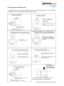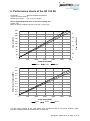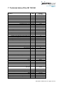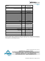
1
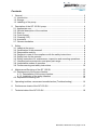
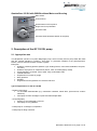
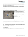
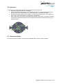
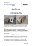
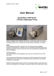
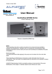
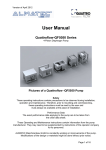
Operating and Installation Instructions Quattroflow 150SU Quaternary Pump 4-Piston-Diaphragm Pump with pump chamber made of plastic (Single-Use) Models with or without control panel and housing; other versions are possible. Please read this manual carefully before start-up of the pump and take care of an appropriate instruction of the operating staff. Attention! Please regard the warning and safety advices! Quattroflow is a brand of ALMATEC Maschinenbau GmbH. ALMATEC is constantly working on improvements of the pump. Modifications of the design or materials might be done without prior notice. Original Instruction Contents 1. General ................................................................................................................ 3 1.1. Introduction ...................................................................................................... 3 1.2. Storage ............................................................................................................ 3 1.3. Labelling of the pump ....................................................................................... 3 2. Description of the QF 150 SU pump .................................................................... 4 2.1. Appropriate use ................................................................................................ 4 2.2. General description of the machine ................................................................. 5 2.3. Start-up ............................................................................................................ 5 2.4. Control panel.................................................................................................... 6 2.5. Cleaning (CIP) ................................................................................................. 6 2.6. Autoclave ......................................................................................................... 7 2.7. Gamma Irradiation ........................................................................................... 7 3. Safety ................................................................................................................... 8 3.1. Labels at the pump .......................................................................................... 8 3.2. Qualification of the personell ............................................................................ 8 3.3. Responsible working ........................................................................................ 8 3.4. Dangers in case of noncompliance with the safety instructions ....................... 8 3.5. Safety hints for the operator ............................................................................. 8 3.6. Safety instructions for maintenance, inspection and mounting operations ....... 9 3.7. Unauthorized reconstruction and spare part usage ......................................... 9 3.8. Inadmissible modes of operation ..................................................................... 9 3.9. Further warning and safety instructions ......................................................... 10 4. Maintenance/Servicing of the QF 150 SU .......................................................... 12 4.1. Replacement of the pump chamber ............................................................... 13 4.1.1. Deinstallation of the pump chamber ..................................................... 13 4.1.2. Installation of the pump chamber ......................................................... 14 4.2. Replacement bearing unit ............................................................................. 15 5. Operating troubles, causes and remedial action (Troubleshooting) ................... 16 6. Performance charts of the QF 150 SU ............................................................... 17 7. Technical data of the QF 150 SU ...................................................................... 18 QF150SU; edition 2014-10; page 2 of 19 1. General 1.1. Introduction These operating instructions are valid for the Quattroflow 150 SU pump. No liability will be undertaken for any damages caused by non-compliance with the operating instructions and service conditions! Original spare parts serve safety purposes. The use of other parts may cancel the liability for the consequences and secondary failures resulting thereof. Manufacturer: ALMATEC Maschinenbau GmbH Carl-Friedrich-Gauss-Str. 5 47475 Kamp-Lintfort, Germany Phone: +49 2842 961-0 Fax: +49 2842 961-40 e-mail: [email protected] Internet: www.quattroflow.com Quattroflow quaternary diaphragm pumps are constructed according to the state of the art and they are reliable. Imminent danger by operating error or misuse can lead to damages of properties and/or persons. The pumps are to be applied for the intended use and in a safety-related proper condition only. 1.2. Storage In general the Quattroflow pump is delivered operational and packaged. If the unit is not installed right away, proper storage conditions are important for a trouble free operation later. The pump has to be protected from wetness, coldness, dirtying, UV-radiation and mechanical influences. The following storage conditions are recommended: - Steady ventilated, dust and vibration free storage room - Ambient temperature between 15°C (59°F) and 25°C (77°F) with a relative humidity below 65% - Prevention of direct thermal influences (sun, heating) 1.3. Labelling of the pump The ALMATEC Maschinenbau GmbH is certified as a modern, quality-orientated enterprise according to DIN EN ISO 9001:2008 and 14001:2009. Before release for dispatch, any Quattroflow pump has to undergo an extended final control. The performance data registered during this are archived in our records and can be read back at any time. As a general rule in the countries of the EU only such machines are allowed to take into operation, which are determined to meet the regulations of the EU machinery directive, the harmonized standards, European standards and the respective national standards. Hence the operator has to verify whether the Quattroflow pump manufactured and delivered properly according to the customers order meets the mentioned requirements. Therefore make sure, before putting the pump into operation, that the pump and the used materials of construction are suitable for the provided application and the installation site. The type label of each Quattroflow pump can be seen on the bottom of the base plate. Besides the serial number of the pump head is fixed at the front cover. QF150SU; edition 2014-10; page 3 of 19 Quattroflow-150 SU with 50W Brushless Motor and Housing Main switch Control Panel Serial Number of Pump Drive Single Use Pump Chamber Pressure Plate CE Name Plate located at bottom of the pump 2. Description of the QF 150 SU pump 2.1. Appropriate use The Quattroflow 150 SU is a 4-piston Diaphragm pump, which is mainly used to pump water-like fluids that are typically handled in research-, pilot plant- or production facilities of the pharmaceutical, biotech, food or cosmetic research centers or plants. Examples: Solutions containing proteins (albumin, IgG, Clotting factors, monoclonal antibodies, enzymes, vaccines.) Solutions of polymers or suspensions (silicon, latex, chromatography media) Cell suspensions (bacteria, yeast, algae, fungi, mammalian cells) colloidal solutions Suspensions of viruses or phage Dairy products Gelatine Supplements and ingredients for cosmetic and food Typical applications for the QF 150 SU - Filtration technology: To recirculate feed/retentate (e.g. membrane cassettes, hollow fibre, spiral wound, ceramic elements) Feed pump for filter cartridges or plate and frame depth filters - Chromatography: Packing of chromatography columns Feed pump to mix gradients - Feed pump for centrifuges or separators - Feed pump for filling machines QF150SU; edition 2014-10; page 4 of 19 2.2. General description of the machine The Quattroflow 150 SU pump is a 4-piston diaphragm pump. The four segments of the pump diaphragm oscillate back and forth. This alternate movement is created by a connector plate that is arranged on a ball bearing. The ball bearing sits on an eccentric shaft. The connector plate does not turn! The stroke of the pistons is determined by the angle of the eccenter. There are eccentric shafts with 5° available. Range of flow rate: 5° eccentric shaft: appr. 1 - 180 L/hr The product wetted pump chamber is provided for single use applications and can easily be replaced after usage. Due to the dispose of the pump chamber after use, efforts for cleaning, validation and risks for cross contaminations are eliminated. Please note: The direction of flow can be adjusted by turning the pump chamber in 90° steps. The Quattroflow 150 SU is self-priming and can run dry. Inside the pump chamber there are no rotating parts that might cause heating up of the product or shed particles. The pump-motor unit is mounted on a stainless steel base plate. In case that the pump will not be mounted on the base plate but in a frame or any other base measures have to be taken that there will be a proper alignment of the motor and the pump. 2.3. Start-up A Quattroflow single-use pump is delivered pre-assembled. Three plastic pump chambers are attached to each new pump unit. One of them has to be installed according to the instructions in Section 4.1. (replacement of the pump chamber), while the other two are for a further replacement. Before start-up of the pump anyone should acquaint oneself with the explanations of the chapter troubleshooting (see page 16). Only by this the defect quickly can be realized and eliminated in case of trouble. Problems which cannot be solved or with an unknown reason should be passed on to the manufacturer. Prior to each use we recommend to flush the pump with a proper fluid (e.g. water or buffer). Prior to the very first use it might make sense to clean and sanitize the pump chamber. A commercial caustic cleaner and/or 0.1N to 0.5N NaOH can be applied. The chosen cleaning agent can be recirculated and also stored inside the pump chamber. For flushing out of any cleaning agent do not recirculate! Check with appropriate analytical methods the success of the flushing procedure.. Recommendation: Test run prior first use! Before using your pump in your process perform a test run to get used to the specific properties of the pump. Please note: ALMATEC Maschinenbau GmbH is also building custom-made pumps and set-ups. These modified pumps can be different from this one that is described in here. However the basic information is applicable to all of the Quattroflow 150 SU Series pumps. Please do not hesitate to contact us for further information. Pay attention to a sufficiently dimensioned piping. A too small piping of the suction line can cause cavitation as well as a loss of performance. QF150SU; edition 2014-10; page 5 of 19 If hoses were used in the suction line, make sure that they do not collapse due to the negative pressure. When installing the pump please consider that around the pump enough space is available for operation and maintenance. Pay attention to the required space needed for assembly and disassembly of the pump chamber (see 4.1.1.). During start-up pay attention to the warning and safety instructions of the following chapter 3 of this manual. 2.4. Control panel In the Quattroflow 150 SU pump is operated with a 50 W brushless Panasonic motor. You can modify the speed of the motor by the control panel on the top of the pump. Main switch. Push to start – the panel lights up Push to speed up (arrow bottom-up) or to speed down (arrow top down) Push "Green button" RUN, to start the pump “MOD button“ Switch between rpm, effiency %, motor power V Display show: "rpm, %, V" (max. speed 3.000 rpm) Push the "Red button" STOP to stop the pump Attention: The optimal motor parameter are set by the factory. Only authorized and qualified personnel should change the parameter of the control panel! Attention! You must study the operating instructions of the PANASONIC–Motor before you make any changes of the parameter! 2.5. Cleaning (CIP) The pump chamber has been designed for single use only. Cleaning is not necessary, as the pump chamber is replaced after each use. QF150SU; edition 2014-10; page 6 of 19 2.6. Autoclave To autoclave an unused pump chamber we recommend the following steps. 1. Removal of pump chamber from packaging 2. Close in and outlet of the pump e.g. by connecting hoses. Ensure that a free interchange of gas and steam over a sterile barrier (e.g. sterile filter) at in- and outlet is available. 3. Autoclaving of the prepared pump chamber in a vacuum autoclave at max. 130°C (266°F) for max. 30 min. Follow instructions of the autoclave manufacturer. 4. After cooling down, the screws of the membrane housing cover and the connectors should be verified and retorqued if necessary. The corresponding screws are marked and shown in the attached picture. 2.7. Gamma Irradiation The single use pump chamber can be gamma irradiated with a maximum dose of 50 kGy. QF150SU; edition 2014-10; page 7 of 19 3. Safety These operating instructions contain basic hints to be observed during installation, operation and maintenance. Therefore, prior to mounting and commissioning, these operating instructions must by all means be read by the fitter as well as the pertinent expert personnel/customer and must always be available at the place of installation of the pump. Not only are the general safety hints listed under this item “Safety” to be observed, but also the special safety hints in other chapters. 3.1. Labels at the pump Marking labels at the pump e.g. - pmax 4 bar - Fluid connections - Direction of flow must not be removed and has to be readable. 3.2. Qualification of the personell The customer is responsible for ensuring that all maintenance, inspection and mounting operations are performed by authorized and qualified expert personnel who have sufficiently informed themselves by thoroughly studying the operating instructions. 3.3. Responsible working Please follow strictly the safety guidelines of this manual, as well as all national and possible internal regulations (e.g. the handling of chemicals, like caustic or acid, the handling of biological materials, the handling of tubing, piping, instrumentation, fittings etc. 3.4. Dangers in case of noncompliance with the safety instructions In case of non-compliance with the safety instructions may cause danger to personnel, equipment and environment. It can cause for example: o Failure of the proper function of the pump/system o Failure of required procedures for maintenance o Danger to personnel by electrical, mechanical, chemical, biological impacts o Danger to equipment and environment through leakage of dangerous substances 3.5. Safety hints for the operator o o o o In case of hot parts protective measures have to be taken. Protecting covers of moving parts (e.g. coupling, cover of motor) must not be removed. Leakages of dangerous products have to be handled without any danger for persons and environment. Statutory regulations must be observed. Dangers by electrical energy are to be excluded (for details please refer to the regulations of the VDE and the local energy supply associations) QF150SU; edition 2014-10; page 8 of 19 3.6. Safety instructions for maintenance, inspection and mounting operations o o o o o o Basically, operations at the pump must be performed during standstill only. The motor has to disconnect from the power supply, e.g. by pulling out the power plug or using a repair switch, and has to secure against unintentional switch-on. This can be realized by a lockable emergency switch. To prevent an accidental re-starting a danger sign should be installed. The operator must ensure that all maintenance, inspection and installation work is performed by authorized and qualified skilled personnel acquainted themselves with this manual. Before starting to disassemble the pump, take care that the pump has been emptied, rinsed, depressurized and disconnected at all phases of the power supply. Both ports piping are to be closed and drained if applicable. If the pump is being deported from the plant, a reference about the delivered liquid has to be attached. Pumps or aggregates handling noxious fluids (e.g. caustic, bio hazardous) must be decontaminated. Immediately following completion of the work, all safetyrelevant and protective devices must be re-installed and/or re-activated. Before putting the pump back into operation, take care of the mentioned instructions of the chapter “start-up” and check the tightness of the pump. Please respect the relevant additional security advices, if the pump has been used for aggressive, dangerous or toxic liquids (e.g. suitable protective equipment according to the safety data sheet of the liquid). In case of a diaphragm rupture, it is possible that residues of the liquid remain behind the diaphragms and in the area of the ring drive. Hence, appropriate safety equipment according to the safety data sheet of the liquid is indispensable. Especially when deliver critical liquids, wear parts, like diaphragms, should be replaced within a preventive maintenance. o Procedure for pump return: According to the requirements of our 14001certification, every unit which is send to ALMATEC for diagnosis or maintenance reasons has to be accompanied by a filled out decontamination-sheet. Otherwise a processing is not possible. The decontamination-sheet is enclosed to this manual. Please pay attention to the further safety regulations. 3.7. Unauthorized reconstruction and spare part usage The use of non-original Quattroflow spare parts or not authorized accessories and reconstructions lead to the lapse of the warranty immediately. When operating such a pump, damages of properties and/or persons cannot be excluded.. 3.8. Inadmissible modes of operation A safety operation of the pump is ensured only by an appropriate use according to the specific data of the enclosed pump data sheet. The values limitations given in the data sheet must not be exceeded. QF150SU; edition 2014-10; page 9 of 19 3.9. Further warning and safety instructions These warning hints are to prevent the user from an inadmissible mode of operation. These warning hints are to be strictly followed to avoid any damage of the pump and/or any danger to personnel The maximum allowed discharge pressure depends on the temperature of the fluid: pmax at room temperature = 4 bar (>40°C = 3 bar) [=58 psi (>104°F = 43 psi)]. An exceeding of the maximum allowed discharge pressure must avoid in any case (do not remove the warning sign at the pump). As a result – if only temporarily – of an exceeding of the allowed discharge pressure the diaphragm can be damaged. The resulting leakage may lead to a loss of the pumping fluid and damages of properties 4 and/or persons. Pay attention to a sufficiently dimensioned piping on the suction and discharge line to prevent a too high pressure in the pump. The pump chamber may not be set under pressure when it is not mounted on the drive. The free cross section of the suction side as well as the length must be measured in such a way to avoid cavitation. The use of a safety device (e.g. pressure switch) can be necessary.. Please make sure that prior to the start of the pump the discharge line is checked. Make sure that there is no flow restriction in the discharge line to avoid any over pressure (e.g. closed valve). Flush the pump prior to use with appropriate fluid (e.g. buffer). Foundation design: The foundation must be designed so that it can take the weight of the pump aggregate on the entire surface. . Please make sure that the pump is operated with the proper mains voltage and frequency to avoid damages and electrical danger. Make sure that the slots for the cooling air are not blocked. Due to the versatile possibilities to use the Quattroflow pump it is highly recommended to check case by case if the pump will be the right tool for the specific application. The user/operator is responsible to perform a proper method of testing if the pump should be applied for his specific application. The chemical and thermal compatibility of the elastomeric parts of the pump with the fluid that will be pumped are to be checked by the operator before the first process run. E.g. Oily, fatty fluids or solvents might cause a swelling and/or destruction of the elastomeric components. If in doubt, please contact the manufacturer! Operating the pump in humid or aggressive air can cause damages to the motor and control box. The control box should not be exposed to spray/splash water or to heat sources. Depending on the conditions of operation, the liquid conveyed might escape from the pump in case of a diaphragm rupture. For further safety requirements the optional equipment diaphragm monitoring is recommended. Pools of liquid which appear in the near outer area of the pump have to be inspected on danger potential, if necessary safety measures are to be taken. Chemical and biological reactions in the product chamber of the pump (mixture of different substances) and the freezing of the liquid have to be avoided. To avoid corrosion the contact of aggressive solutions (e.g. NaCl, HCl) with the outer stainless steel surfaces of the pump (e.g. hood, base plate) has to be prevented. The Quattroflow pump is a positive displacement pump and can theoretically generate an infinitely high pressure even at low speed (rpm). Prior to each start of the pump check and make sure that the discharge line is not closed or restricted. The design of the discharge line must not build up a pressure of > 4 bar (58 psi). If suction and/or discharge line are flexible tubing, then make sure that these tubing do have the proper pressure rating for the full range of temperatures that are applied. Please follow the general safety guidelines when handling chemical fluids (wear gloves and/or glasses) before the pump chamber will be opened. Never operate the pump without coupling protection and motor housing. QF150SU; edition 2014-10; page 10 of 19 Quattroflow pumps can lead to bruises when lifting, sinking or assembling them. Appropriate accessories and safety equipments are to be used. Big and heavy modules have to fixed and secured to lifting gears when transporting/replacing them. Disconnect mains before doing any maintenance! The housing of the control box or the motor is to be opened only by skilled personnel. Check the electrical cables before connecting to mains supply. During all maintenance work it has to be ensured that no explosive atmosphere can arise. Appropriate protection equipment is recommended. The Quattroflow 150 SU must not be operated in explosion-proof areas. Special versions for “ATEX” applications are available. Please contact the manufacturer. Attention! Inadmissible modes of operation, arbitrary reconstruction, spare parts production and/or any changes of the design (without admission of the manufacturer) may cancel the liability for the consequences resulting there from. QF150SU; edition 2014-10; page 11 of 19 4. Maintenance/Servicing of the QF 150 SU Due to the robust construction the Quattroflow pump are widely maintenance-free. The ball bearings do not need any extra lubrication. Component Shaft-bearing-cap unit Maintenance interval 1000 h operating hours, at least once a year Motor Pay attention to the maintenance information of the manual of the motor Pay attention to the maintenance information of the manual of the coupling Pay attention to the maintenance information of the manual of the gear Coupling Gear (option) Action Replacement of the complete unit (kit order no. PSKITWLC155) In case that the diaphragm is broken the pump chamber should be replaced. Then it is also recommended to check the ball bearings. For corrosion reasons or a clearly audible operating noise the parts of the bearing service kit should be also replaced. (PSKITWLC155). Please follow the general guidelines and safety advices when handling with chemicals. Disconnect mains supply before opening the pump housing! Basically, operations at the pump must be performed during standstill only. The motor has to disconnect from the power supply, e.g. by pulling out the power plug or using a repair switch, and has to secure against unintentional switch-on. This can be realized by a lockable emergency switch. To prevent an accidental re-starting a danger sign should be installed.. After purging the pump with air there might be a small residual amount of fluid inside the pump chamber. Flush the pump chamber thoroughly and check the rinse fluid. The dismounting and mounting of the pump should be done on a rigid table or work bench. Please note: the pump is heavy. All further warning and safety instruction of chapter 3 has to be respected. QF150SU; edition 2014-10; page 12 of 19 4.1. Replacement of the pump chamber The Quattroflow 150SU pump is designed for use in single-use processes. The wetted pump chamber made of plastic can be replaced quickly and easily. The simple disposal of the pump chamber saves time and money because the cost of cleaning, sterilization or a sophisticated cleaning validation is inapplicable. To each new pump unit three single-use product chambers will be delivered. More can be ordered as a set of three pieces (PQ15DISPP). The replacement of the pump chamber can be conducted by the operator. Please follow the drawings for the installation and deinstallation. Before starting the disassembly ensure that the pump is not in operation and can not be accidentally taken into operation. Also, make sure that the system was emptied before the change. 4.1.1. Deinstallation of the pump chamber Needed tools: Allen key 3 and 8 mm; screwdriver 1. 2. 2. Loose screw of clamping ring inside the ring drive 1. Loosen four hex bolts and remove pressure plate together with pump chamber 1. Loose and remove hexagon screw plug Pressure Plate 3. Remove pump chamber QF150SU; edition 2014-10; page 13 of 19 4.1.2. Installation of the pump chamber Needed tools: Allen key 8 mm; Torque wrench with hexagon socket (3 mm) (e.g. Hazet 5108-2CT with 8501X-3) Torque-screw driver with (e.g. Hazet 6001-1.5/3 with 2215LG-PH2) 1. 2. 1. Install four bolts together with pressure plate. Apply torque of 3 Nm (2.2 lb-ft) Install pump chamber Pressure Plate 3. 1. Fasten screw of clamping ring inside the ring drive. Apply tightening torque of 0.6 Nm (0.45 lbft) 2. Install screw to close ring drive QF150SU; edition 2014-10; page 14 of 19 4.2. Replacement bearing unit The replacement of the bearing unit (shaft-bearing-cap unit, kit PSKITWLC155) can be conducted by the operator. The following drawings describe it step-by-step. Between both coupling halves has to be a gap of 2-3 mm (0.079 – 0.118 inch). For further questions and ordering of spare parts please contact the manufacturer. QF150SU; edition 2014-10; page 15 of 19 5. Operating troubles, causes and remedial action (Troubleshooting) No. Pump does not start Pump does not prime Delivery is not obtained or reduced 1 X 2 X 3 X X 4 5 X X X X 6 Pressure head is not obtained Irregular pump delivery Pump operates noisily Pump is leaky Motor gets too warm Display show Error code The screws of the pump-chamber maybe not tightened enough. Fix it! Check the direction of flow showed by the arrow on the pump, in case of wrong way, turn the pump head. Check suction pipeline and TC- seals for tightness. Check suction head-increase suction line cross section. X X X X X X X 7 X 8 X X X X 9 X 10 X 11 X 12 X 13 X 14 X 15 X 16 X X X X X X 17 X 18 X X 19 20 21 Causes and remedial action Operating troubles X X X X Check viscosity of liquid pumped. Check pump speed. Control speed of drive motor. Check voltage and frequency and the fuse (6,3A T in the control box) Avoid air inclusions in the liquid to be pumped. Check pressure head-open valve in discharge line completely, remove obstruction in discharge line. Pressure line completely or partly clogged, diaphragm maybe broken, change diaphragm! The diameter of the pipes in suction or pressure line are too small. Check the coupling halves. They must be fixed with 2-3mm space. Check longitudinal play of coupling rod pins. The spider might be worn. Check whether foreign bodies in pump. Disassemble pump, remove foreign bodies, replace defective parts. Pump stopped by the thermal circuit breaker. Please allow the motor to cool down – please reduce the power consumption. Bearings are worn or defective Disassemble pump, replace the shaft – bearing – cap unit (PSKITWLC155) The valves are dry (e.g. not in use for a long time), deformed or worn. Change valve or wet the pump. The diaphragm is burst ( the discharge pressure was too high) – replace the pump chamber O–rings between valve plate and pump housing are defective PSKITQ12. X Align coupling accurately X The clamping ring screw got loose – fixe it! X Parameters of the control panel are wrong – check basic settings. QF150SU; edition 2014-10; page 16 of 19 6. Performance charts of the QF 150 SU Testmedia: Water at ambient temperature Type of eccentric shaft: 5° Discharge pressure: 0 to 4 bar (0 to 58 psi) Shows approximate flow rates as function of pump rpm. Please note: Motor is directly coupled to pump: Pump rpm = motor rpm 200 3 Flow rate [L/h] 160 2,5 140 120 2 100 1,5 80 60 1 40 Flow rate [L/min] 180 0,5 20 0 0 500 1000 1500 2000 2500 Pump speed [RPM] 0 bar 2 bar 4 bar 0 500 1000 1500 2000 2500 Pump speed [RPM] 0 psi 29 psi 58 psi 0 3000 1,0 US Gallon per minute [GPM] 0,9 0,8 0,7 0,6 0,5 0,4 0,3 0,2 0,1 0,0 3000 The flow rates showing at the chart above were ascertained with a new pump chamber under standard conditions after the final assembly of the pump. QF150SU; edition 2014-10; page 17 of 19 7. Technical data of the QF 150 SU Unit QF150 SU Standard Motor Eccentric shaft 5° l/h (gph) 180 (48) Eccentric shaft 5° l/h (gph) 1 Temperature of fluid < 40°C bar (psi) 4 (58) Temperature of fluid > 40°C bar (psi) 3 (43) Fluid °C (°F) 60 (140) Autoclave °C (°F) 130 (260) m (ft) 2-3 (6.6-9.8) Approximated volume per revolution at free output ml 1,2 Filling volume without connectors ml 15 Description Flow rate max.: Flow rate min.: Pressure: Temperature max.: Suction lift dry at: 3000 rpm Eccentric shaft 5° Volume specifications: Residual volume (after idle with high-speed motor) Product wetted surface (approx.) Speed range pump ml 1-3 cm² (inch²) 112 (17) rpm 10-3000 " 1/4" TC Connection specification inlet (standard) Connector Flange diameter mm (inch) 25 Internal diameter mm (inch) 4,7 Connection specification outlet (standard) " 1/4" TC Flange diameter Connector mm 25 Internal diameter mm (inch) 4,7 (0.19) Position of connectors Inline Number of flow directions Diameter drive shaft 4 mm 7 Product wetted materials (standard): Pump housing PP Valve plate PP Diaphragms TPE Valves EPDM O-rings EPDM Non-product wetted materials (standard): Membrane cover PP Bearing housing SS316L Base plate SS316 Hood SS316 Dimensions pump with motor and housing: Weight pump with motor and housing Custom tarif number Length mm (inch) 285 (11.22) Width mm (inch) 115 (4.53) Height mm (inch) 184 (7.24) kg (lb) Ca.7 (15.8) 84138100 QF150SU; edition 2014-10; page 18 of 19 Description Unit QF150 SU Standard Motor Certificates/proofs (optional): USP <88> Cl. VI; FDA21CFR177; BSE/TSE Safe Elastomere (product wetted) Motor/Gear: Manufacturer (standard) Panasonic Type Rated speed MBMC5A2/(A1) min-1 3000 Voltage V 230/(option: 115) Ampacity A 1,1 Power KW 0,05 Shaft diameter mm 8 IP 55 RAL black/alu IP protection class Color Forced ventilation in hood Coupling KTR (Rotex) Gear ratio n/a Control box (optional): Controller (integrated in motor) Type Manufacturer (standard) n/a Designation n/a Analog input (optional) 0-5V Protection class IP54 230V/ 50Hz 1P; optional 110V/60 Hz 1P Power supply Housing material SS316 Dimensions (length x width x height) mm (inch) 200 x 110 x 160 (7.87 x 4.33 x 6.30) Weight approx. kg (lb) n/a All technical data relate to a Quattroflow pump in the standard version. Special designed pumps (e.g. special product connections) may have different data that can be found in the advanced documentation for each Quattroflow pump. Subject to change without notice, 2014-10 ALMATEC Maschinenbau GmbH Carl-Friedrich-Gauss-Str. 5 · D-47475 Kamp-Lintfort, Germany Telephone +49 2842 961-0 · Fax +49 2842 961-40 www.quattroflow.com · [email protected] QF150SU; edition 2014-10; page 19 of 19