1
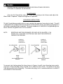
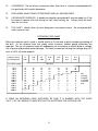
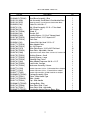
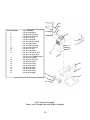
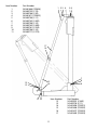
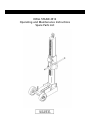
DRILL STAND 2512
Operating and Maintenance Instructions
Spare Parts List
Some dust created by power sanding, sawing, grinding, drilling and other construction activities contains chemicals known to cause cancer, birth defects or other
reproductive harm. Some examples of these chemicals are:
·Lead from lead-based paints,
·Crystalline silica from bricks and cement and other masonry
products and
·Arsenic and chromium from chemically-treated lumber.
Your risk from these exposure varies, depending on how often you do this type of
work. To reduce your exposure to these chemicals: work in a well ventilated area
and work with approved safety equipment, such as those dust masks that are specially designed to filter out miscroscopic particles.
·REFER TO MANUAL·
Introduction
Congratulations on your selection of a Target 2512 Drill Stand. We are certain you will be
pleased with your purchase of one of the finest drill stand on the market.
We want to help you get the best performance from your new machine and to operate it
safely. This manual contains the information on how to do that. Please read this manual
thoroughly, as it contains important information on operational safety, maintenance and
suggestions on how to get the best performance from your Drill Stand.
Best Wishes
Target
Hazard Symbols
Explosive FuelExplosive Fuel
Gasoline is extremely flammable and its vapors can explode if ignited.
Store
gasoline only
in approved containers, in well-ventilated,
unoccupied buildings, away from sparks or flames.
Do not fill the tank
while the engine is hot or running, since spilled fuel could ignite if it
comes in contact with hot parts or sparks from ignition. Do not start the
engine near spilled fuel. Never use gasoline as a cleaning agent.
Engine components can get extremely hot from operation. To prevent
severe burns, do not touch these areas while the engine is running
or immediately after it is turned off. Never operate the engine with heat
shields or guards removed.
Keep hands, feet, hair and clothing away from all moving parts to prevent
injury. Never operate the engine with covers, shrouds or guards removed.
Engine exhaust gasses contain poisonous carbon monoxide. Carbon
monoxide is odorless, colorless and can cause death if inhaled. Avoid
inhaling exhaust fumes and never run the engine in a closed building or
confined area.
Never tamper with the governor components or settings to increase the
maximum speed. Severe personal injury and damage to the engine
or equipment can result if operated at speeds above maximum.
1
General Cautions and Warnings
Never attempt any adjustment or repair to the machine while the engine is
running.
Never put hands or feet under the machine while the engine is running.
Serious injury will occur.
Never run the engine in an unventilated area.
Never fill the fuel tank with the engine running. Spilling diesel fuel on
a hot engine may cause a fire or explosion.
Always wear safety glasses and ear protection when operating this
machine.
2
GENERAL INSTRUCTIONS
This instruction manual describes the assembly, operation, maintenance and safety precautions for proper use of the drill stand. This equipment is intended for industrial applications
by experienced operators.
IMPROPER USE OF THIS EQUIPMENT OR IMPROPER MACHINE ALTERATIONS MAY BE
EXTREMELY DANGEROUS.
The operator is cautioned against using this machine before having read and fully understood the instructions presented in this manual.
USER RESPONSIBILITIES
It is the operator’s responsibility to be fully aware of the requirements for operator safety and the safety of co-workers, observers and public at large, to provide a safe working environment and to follow proper safety procedures when operating this equipment. Operators
must use approved ear protection or plugs, safety hat, eye protectors, gloves safety shoes and
any other personal protective equipment required for compliance with standard safety practices
or federal, state and local codes and regulations, pertaining to safety, pollution, noise, etc.
MODEL 2512 DRILL STAND ASSEMBLY
The Model 2512 Drill Stand consists of a Column, Base, Carriage and Motor Adapter as
shown in Figure 1.
1.
2.
3.
4.
5.
Attach Column to Base with 1/2-13 x 3 Hex Head Bolts (541403540).
Install keys in Carriage and Adapter.
Install Handle into Pinion as shown in on page 6. Install Cap on handle.
Install Carriage on Column and adjust clearance Wear Plates with screw (541403762) using
1/8” hex key.
Attach drill motor (not provided) to Adapter with capscrews provided and secure adapter
to Carriage with capscrews (541403761).
LOCK CARRIAGE TO COLUMN WHEN NOT IN USE BY TIGHTENING LOCK SCREW
(541401738)
OPERATION
1.
Set 1/2” anchor (not provided) and place Base over anchor.
2.
Adjust leveling screws to positions Column properly.
3.
Secure Base to anchor.
3
BEFORE STARTING DRILL MOTOR, MAKE SURE DRILL STAND IS SECURELY
ATTACHED TO SURFACE TO BE DRILLED.
MAINTENANCE
Clean the Drill Stand after each use. Check carriage play on the Column and adjust the
Wear Plates if required. Inspect and tighten all capscrews.
GROUNDING INSTRUCTIONS
This drill should be grounded while in use to protect the operator from electric shock. The drill
is equipped with an approved three-conductor cord and three-prong, grounding-type plug to fit
the proper grounding-type receptacle. The green conductor in the cord is the grounding wire.
Never connect the green wire to a live terminal.
NOTE:
RECEPTACLE MUST BE GROUNDED FOR SAFE USE OF ADAPTER: IF IN
DOUBT CALL QUALIFIED ELECTRICIAN AND HAVE THE RECEPTACLE
CHECKED FOR GROUND.
COVER OF
GROUNDED
OUTLET BOX
Grounding Blade
COVER OF
GROUNDED
OUTLET BOX
Grounding Blade
NEMA
L5-20
PLUG AND RECEPTACLE
FIGURE A
NEMA
L6-20
PLUG AND RECEPTACLE
FIGURE B
To connect twist locking plugs like those shown in Figures A and B, insert the plug into a matching outlet. When the plug is fully inserted, turn it clockwise until it locks. This prevents the plug
from being pulled out accidentally. To remove the plug, twist it counterclockwise to unlock it
and remove it from the outlet.
4
SAFETY INSTRUCTIONS FOR ALL ELECTRIC POWERED DRILLS
WHEN USING ELECTRIC TOOLS, BASIC SAFETY PRECAUTIONS SHOULD ALWAYS BE
FOLLOWED TO REDUCE THE RISK OF FIRE, ELECTRIC SHOCK AND PERSONAL INJURY
INCLUDING THE FOLLOWING ITEMS. READ ALL INSTRUCTIONS AND SAVE THEM
FOR FUTURE REFERENCE.
1.
GROUND ALL TOOLS. If the tool is equipped with a three prong plug, it should be
plugged into a three hole electrical receptacle. If an adapter is used to accomodate a
two hole receptacle, the grounding ear must be attached to a known ground. Never
remove the third prong.
2.
DON’T FORCE DRILL. It will do the job better and safer at the rate for which it was
designed.
3.
WEAR PROPER APPAREL. No loose clothing or jewelry to get caught in moving parts.
Rubber gloves and insulated non-skid footwear are recommended when working out
doors. Wear protective covering to contain long hair.
4.
USE SAFETY GLASSES at all times.
5.
DON’T ABUSE CORD. Never carry the tool by its cord or yank it to disconnect from the
receptacle. Keep cord from heat, oil and sharp edges.
6.
DISCONNECT TOOLS. When not in use; before servicing, when changing accessories such
as bits, extension, etc.
7.
GUARD AGAINST ELECTRIC SHOCK. Prevent body contact with grounded surfaces such
as pipes, radiators, ranges and refrigerator enclosure.
8.
REMOVE WRENCHES. Form a habit of checking to see that wrenches are removed from
drill spindle and bit before turning it on.
9.
MAINTAIN DRILL WITH CARE. Keep drill clean at all times for best and safest perform
ance. Follow instructions for lubricating. Keep handles dry, clean and free of oil or
grease. Inspect switches, tool cords and extension cords periodically and have them
repaired if damaged. Check moving parts for alignment and binding as well as for
breakage and improper mounting. Damaged parts should be repaired or replaced.
10.
AVOID ACCIDENTAL STARTING. Don’t carry a plugged-in drill with your finger on the
switch. Be sure the switch is turned off before plugging in a drill. Do not use a drill if
the switch does not turn it on or off.
11.
WEAR EAR PROTECTORS when using for extended periods.
5
12.
ACCESSORIES. The use of any accessories other than what is listed or recommended for
this particular drill may be hazardous.
13.
KEEP HANDS AWAY FROM CUTTING EDGES AND ALL MOVING PARTS.
14.
USE INSULATED SURFACES. A double-insulated or grounded drill may be made live if the
bit comes in contact with live wiring in a wall, floor, ceiling, etc. Always check the work
area for live wires.
15.
STAY ALERT. Watch what you are doing and use common sense. Do not operate drill
when you are tired.
EXTENSION CORD CHART
When an extension cord is used, it should also be a 3 wire cord to permit proper grounding of
the drill. As the distance from the supply outlet increases, heavier gauge extensions are
required. The use of extension cords of inadequate size wire causes a serious drop in voltage,
loss of power and possible motor damage. This table is based on limiting line voltage drop to 5
volts at 150% of rated amperes.
Ampere rating
(on Nameplate)
02.00
2.103.4
3.55.00
Ext. Cable Length
25 Ft.
50 Ft.
75 Ft.
100 Ft.
150 Ft.
200 Ft.
300 Ft.
400 Ft.
500 Ft.
600 Ft.
800 Ft.
1000 Ft.
5.107.0
7.1012.0
12.116.0
16.120.0
16
14
12
10
8
8
6
4
4
2
2
1
14
12
10
8
8
6
4
4
2
2
1
0
12
10
8
8
6
4
4
2
2
1
0
0
Wire Size
18
18
18
18
16
16
14
12
12
10
10
8
18
18
18
16
14
14
12
10
10
8
8
6
18
18
16
14
12
12
10
8
8
6
6
4
18
16
14
12
12
10
8
6
6
4
4
2
Not
normally
available
as flexible
extension
cord.
IF USING AN EXTENSION CORD OUTDOORS, BE SURE IT IS MARKED WITH THE SUFFIX
“W-A” (“W” IN CANADA) TO INDICATE THAT IS IS ACCEPTABLE FOR OUTDOOR USE.
6
2512 Drill Stand - Parts List
Part No.
541403894 D (752000)
541401123 (189A)
541401126 (187A)
541403523 (C46)
541403731 (C8)
541403798 (C10)
541401791 (752008)
541402238 (C48)
541403534 (C382)
541401785 (752015)
541403473 (752016)
541403540 (C34)
541401774 (752018)
541401768 (752019)
541403763 (C379)
541401756 (752023)
541403762 (C380)
541401752 (752024)
541401747 (752025)
541401743 (752026)
541403761 (C381)
541401738 (752033)
541401734 (752034)
541403774 (C294)
541403771 (C341)
541400277 (73234)
541403893 D (752040)
541401724 (752041)
541401719 (752042A)
541401713 (752043)
541403880 D (752045)
541401704 (752046)
541401700 (752047)
541403897 D (752220)
Description
Qty.
Small Base Assembly - Blue
Axle Assembly, Small Base & Combination Base
1
1
1
4
2
2
2
4
4
1
1
2
1
2
10
2
6
1
1
1
4
1
1
4
4
4
1
1
1
1
1
2
1
1
Wheel Assembly, Small Base & Combination Base
Cotter Pin, Axle 1/8 x 1"
Bolt, Wheel Assembly 1/2-13 x 1" Hex Head
SAE Washer, 1/2"
Wheel, 5"
Washer, 5/8"
Leveling Screws, 1/2-13 x 4" Square Head
Column w/Rack, 2-1/2" Square x 42"
Rack Gear
Column Bolt, Hex Head 1/2-13 x 3"
Motor Adapter Plate
Key, 3/8" Square
Wear Plate Screw, 10-32 x 3/8" Flat Head
Wear Plate - Adjustable - Narrow
Adjustment Screw, Wear Plate 1/4-20 x 3/8" Socket Hd
Bushing, Bronze - Small
Bushing, Bronze - Large
Retaining Ring, Pinion
Motor Adapter Capscrew 3/8-16 x 1-1/2"
Lock Screw, Carriage
Jackscrew Assembly, Column
Socket Capscrew 1/4-20 x 1" Milwaukee Mtr to Adapter
Socket Capscrew 1/4-28 x 1" Dewalt Mtr to Adapter
Socket Capscrew M8 x 25 MM Cardi Mtr to Adapter
Carriage Assembly - Blue
Pinion - Slide Handle Type
Slide - Handle
Cap - Slide Handle
Carriage Body - Blue
Wear Plate, Wide - Fixed
Wear Plate, Wide - Adjustable
Combination Anchor/Vacuum Base - Blue
7
2512 Drill Stand - Parts List
Part No.
541403929 D (752225)
541401640 (752226A)
541401590 (410)
541402423 (A41)
541401596 (408)
541402422 (A42)
541401635 (752227)
541401491 (447)
541401495 (445)
541201985 (752221)
541403927D (752222)
541201981 (752223)
541402234 (C494)
541401572 (412)
541403731 (C8)
541403798 (C10)
Description
VACUUM ASSEMBLY
Vacuum Pump w/Fittings and Slot Cap - Blue
Bracket, Pump to Base
Vacuum Pump Only - 220 Volt
Nipple, 1/4 x Close Pipe
Water Trap
Tee, 1/4" Pipe
Hose, Pump to Slot Cap
Vacuum Gauge
Release Valve
Gasket, Combo Base
Slot Cap - Blue
Gasket, Slot Cap
Capscrew, Bracket to Pump, 10-32 x 5/8
Muffler
Bolt, Bracket to Base, 1/2-13 x 1
SAE Washer, 1/2"
541 40 10-37 (223)
541 40 36-77 (227)
541 40 10-18 (229)
541 20 19-11 (230)
541 40 10-03 (237)
541 40 09-99 (238)
541 20 19-07 (248)
541 40 14-46 (473)
541 40 14-44 (474)
541 40 14-42 (475-1)
541 40 14-40 (475-2)
541 40 14-38 (476)
541 40 14-36 (477)
541 40 16-08 (30622)
541 40 37-94 (C139)
541 40 22-70 (C231)
541 40 36-15 (C255)
541 40 37-67 (C375)
541 40 37-66 (C376)
541 40 37-64 (C378)
541 40 36-14 (C383)
SWITCHBOX ASSEMBLY
Receptacle, 20A, Single
Strain Relief
Switch, Motor
Boot, Auxiliary Switch
Boot, Motor Switch
Switch Plate
Ammeter, 0-30A
Mounting Bracket (2812 Carriage Only)
Clip - Male Dovetail
Box - Front
Box - Back
Receptacle, 15A, Single
Plug, 30A, Twist Lock
Switch, Auxiliary
Lock Nut, 1/4-20
Capscrew, Socket 1/4-20 x 1/2"
Jam Nut, 1/2-20
Capscrew, Button Head 10-32 x 1/4"
Capscrew, Button Head 6-32 x 3/8"
Capscrew, Button Head 8-32 x 3/8"
Jumper, Switch
8
Qty.
1
1
1
3
1
2
1
1
1
1
1
1
4
1
1
1
1
1
1
1
1
2
1
1
1
1
1
1
1
1
2
2
1
4
2
2
1
2
Item Number
1
2
3
4
5
6
7
8
9
10
11
12
13
14
15
16
Part Number
541
541
541
541
541
541
541
541
541
541
541
541
541
541
541
541
40
40
40
40
40
40
40
40
40
40
40
40
40
40
40
40
38-80
17-04
17-68
17-71
17-47
17-24
17-13
17-19
17-00
17-56
37-61
37-62
17-38
37-63
17-52
17-43
(752045) Cast Only
(752046)
(752019)
(752018)
(752025)
(752041)
(752043)
(752042A)
(752047)
(752023)
(C381)
(C380)
(752033)
(C379)
(752024)
(752026)
1
3
16
15
4
5 6
14
13
7
8
12
11
10
9
17
17
18
19
20
21
22
23
24
25
26
27
28
541
541
541
541
541
541
541
541
541
541
541
541
541
541
541
541
40
40
40
40
40
40
40
40
40
40
40
40
40
40
40
40
17-34 (752034)
17-31 (752038) Key Incl.
37-74 (C294) Milwaukee
37-71 (C341) DeWalt
02-77 (73234) Cardi
35-40 (C34)
38-94 (752000)
11-26 (187A) Assy
11-23 (189A) Axle
17-91 (752008) Wheel
37-31 (C8)
37-98 (C10)
35-34 (C382)
38-93 (752040) Assy
17-85 (752015) Column
34-73 (752016) Rack Only
19
28
18
27
26
20
25
21
22
24 23
2512 Drill Stand
9
Item Number
1
2
3
4
5
6
7
8
9
10
11
12
13
14
15
16
17
18
19
20
21
Part Number
541 40 16-02 (407)
541 40 39-27 (752222)
541 40 16-46 (752223)
541 40 37-31 (C8)
541 40 37-98 (C10)
541 40 16-40 (752226A)
541 40 35-34 (C382)
541 40 38-96 (752220)
541 20 19-85 (752221)
541 40 37-31 (C8)
541 40 37-98 (C10)
541 40 11-26 (187A) Assy
541 40 11-23 (189) Axle
541 40 17-91 (752008) Wheel
541 40 22-34 (C494)
541 40 16-35 (752227)
541 40 24-22 (A42)
541 40 24-23 (A41)
541 40 24-22 (A42)
541 40 14-91 (447)
541 40 14-95 (445)
541 40 24-23 (A41)
541 40 15-96 (408)
18
19
17
16
20
21
15
1
14
2
4
5
6
3
13
7
8
12
9
11
10
2512 Vacuum Assembly
Shown with Combo Base and Wheel Assembly
10
Item Number
1
2
3
4
5
6
7
8
9
10
11
Part Number
541401666 (752056)
541403732 (C-79)
541403788 (C-20)
541401671 (752055)
541403796 (C-11)
541403743 (C-495)
541403798 (C-10)
541403742 (C-496)
541403781 (C-254)
541403798 (C-10)
541403777 (C-273)
1 23 4
56
17
16
7
8
9
15
14
13
12
Item Number
12
13
14
15
16
17
11 10
11
Part Number
541403591 (C-442)
541403734 (C-71)
541401694 (752051)
541401688 (752052)
541401677 (752053)
541401683 (752053)
ELECTROLUX CONSTRUCTION PRODUCTS
Product Limited Warranty
Equipment manufactured by Electrolux Construction Products (a division of Electrolux
Professional Outdoor Products, Inc.) is warranted to be free from defects in material and
workmanship if operated properly, without abuse or negligence in normal service applications
for a period of two (2) years from date of purchase by the original consumer purchaser
with the following exception:
Target DR 150 Core Drills Three (3) months
Felker FTS-50
Three (3) months
Felker FTS-70
Six (6) months
Felker TM-75
One (1) year
Felker FTS-150
One (1) year
Felker
Felker
Felker
Felker
FRS-30
FRS-38
FRS-51
Track Master II
One
One
One
One
(1)
(1)
(1)
(1)
year
year
year
year
Keep all payment records (bill of sale/delivery slip). The date on these records establishes
the warranty period. Should warranty service be required, you must show proof of purchase. If
proof of purchase cannot be supplied, the warranty period will determined from the date of
manufacture of the product.
All warranty claims will be determined after inspection at a designated facility. Write or
call Electrolux at 17400 W. 119th Street, Olathe, KS 66061, 800-365-5040, for instructions. The
customer must prepay the freight and absorb any labor expense required to return or replace a
product submitted to Electrolux for warranty consideration. Electrolux will pay return shipping
expenses for repaired or approved replacement products. Under no circumstances will
Electrolux be responsible for incidental or consequential damages.
The responsibility of Electrolux under this warranty is limited to the repair or replacement,
at our option, of defective parts and assemblies at its plant in Olathe, KS and Torrance, CA, and
does not cover engines, motors, pumps, transmissions and other trade accessories sold with,
attached to, or operated with Electrolux products. Such components, parts and accessories are
subject to the original manufacturer’s warranty policy and procedures. Normal wear items, such
as filters, V-belts and wheels are not covered under this warranty.
The Electrolux warranty does not apply to defects caused by abuse, modifications, low
voltage, acts of God, unreasonable use, faulty repairs made by others or damage or loss caused
by failure to provide reasonable maintenance. All warranties are void if the equipment or any
of its components are altered or modified by the purchased, or if the product is used in a manner or with a blade not recommended by the manufacture.
The foregoing express warranties are in lieu of all other warranties. ELECTROLUX
EXPRESSLY DISCLAIMS ALL OTHER WARRANTIES, INCLUDING, WITHOUT LIMITATION, THE
IMPLIED WARRANTIES OF MERCHANTABILITY AND FITNESS FOR A PARTICULAR PURPOSE.
Some states do not allow exclusion of warranties or limitations of damages, so the limitations and exclusions contained in this warranty may not apply to you. This warranty gives you
specific legal rights. You many have additional rights, which vary from state to state.
Target Corporate Office
17400 West 119th Street
Olathe, Kansas 66061
Customer Service: 800-288-5040
Customer Serv. Fax: 800-825-0028
Corporate Office: 913-928-1000
Corp. Office Fax: 913-438-7951
Target California
Customer Service: 310-381-3100
Customer Serv. Fax: 310-381-3194
Target Canada
Customer Service: 800-461-9589
Customer Serv. Fax: 800-728-1907
Target International
Customer Service: 913-928-1300
Customer Serv. Fax: 913-438-7938
DUST WARNING
Cutting, especially when DRY cutting, generates dust that comes from the material being cut,
which frequently contains silica. Silica is a basic component of sand, quartz, brick clay, granite and
numerous other minerals and rocks. Exposure to excessive amount of such dust can cause:
Respiratory diseases (affecting your ability to breath), including chronic bronchitis, silicosis
and pulmonary fibrosis from exposure to silica. These diseases may be fatal;
Skin irritation and rash; and
Cancer according to NTP* and IARC*
* National Toxicology Program / International Agency for Research on Cancer
Take precautionary steps
Avoid inhalation of and skin contact with dust, mist and fumes;
Wet cut when feasible, to minimize dust;
Wear and ensure that all bystanders wear appropriate respiratory protection such as dust
masks designed to filter out microscopic particles. (See OSHA 29 CFR Part 1910.1200)
California Prop 65 Warning:
Use of this product can cause exposure to materials known to the State of California to cause cancer
and/or birth defects or other reproductive harm.
www.targetblue.com