1
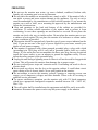
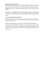
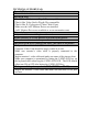
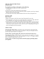
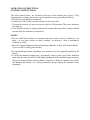
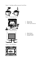
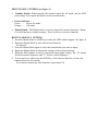
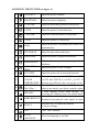
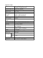
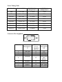
FT920
19” Flat CRT
User’s
Manual
By Envision Peripherals, Inc.
www.aocmonitor.com
Thank you very much for choosing the AOC Color Monitor. We recommend that you
take a few minutes to read carefully through this brief but comprehensive manual
before installing and switching on the monitor. Please keep this manual in a safe place
for your future reference. Plug & Play Drivers for the AOC Series Monitors are
available at: www.aocmonitor.com
CHECKING THE CONTENTS OF THE MONITOR PACKAGE
The product package should include the following items:
1. Monitor
2. Owner's Manual
3. Power Cord
4. Swivel Base
FCC Class B Radio Frequency Interference Statement WARNING: (FOR FCC
CERTIFIED MODELS)
NOTE: This equipment has been tested and found to comply with the limits for a
Class B digital device, pursuant to Part 15 of the FCC Rules. These limits are designed
to provide reasonable protection against harmful interference in a residential
installation. This equipment generates, uses and can radiate radio frequency energy,
and if not installed and used in accordance with the instructions, may cause harmful
interference to radio communications. However, there is no guarantee that interference
will not occur in a particular installation. If this equipment does cause harmful
interference to radio or television reception, which can be determined by turning the
equipment off and on, the user is encouraged to try to correct the interference by one
or more of the following measures:
1. Reorient or relocate the receiving antenna.
2. Increase the separation between the equipment and receiver.
3. Connect the equipment into an outlet on a circuit different from that to which the
receiver is connected.
4. Consult the dealer or an experienced radio/TV technician for help.
NOTICE :
1. The changes or modifications not expressly approved by the party responsible for
compliance could void the user's authority to operate the equipment.
2. Shielded interface cables and AC power cord, if any, must be used in order to
comply with the emission limits.
3. The manufacturer is not responsible for any radio or TV interference caused by
unauthorized modification to this equipment. It is the responsibilities of the user to
correct such interference.
WARNING :
To prevent fire or shock hazard, do not expose the monitor to rain or moisture.
Dangerously high voltages are present inside the monitor. Do not open the cabinet.
Refer servicing to qualified personnel only.
PRECAUTIONS
z Do not use the monitor near water, e.g. near a bathtub, washbowl, kitchen sink,
laundry tub, swimming pool or in a wet basement.
z Do not place the monitor on an unstable cart, stand, or table. If the monitor falls, it
can injure a person and cause serious damage to the appliance. Use only a cart or
stand recommended by the manufacturer or sold with the monitor. If you mount the
monitor on a wall or shelf, use a mounting kit approved by the manufacturer and
follow the kit instructions.
z Slots and openings in the back and bottom of the cabinet are provided for
ventilation. To ensure reliable operation of the monitor and to protect it from
overheating, be sure these openings are not blocked or covered. Do not place the
monitor on a bed, sofa, rug, or similar surface. Do not place the monitor near or over
a radiator or heat register. Do not place the monitor in a bookcase or cabinet unless
proper ventilation is provided.
z The monitor should be operated only from the type of power source indicated on the
label. If you are not sure of the type of power supplied to your home, consult your
dealer or local power company.
z The monitor is equipped with a three-pronged grounded plug, a plug with a third
(grounding) pin. This plug will fit only into a grounded power outlet as a safety
feature. If your outlet does not accommodate the three-wire plug, have an electrician
install the correct outlet, or use an adapter to ground the appliance safely. Do not
defeat the safety purpose of the grounded plug.
z Unplug the unit during a lightning storm or when it will not be used for long periods
of time. This will protect the monitor from damage due to power surges.
z Do not overload power strips and extension cords. Overloading can result in fire or
electric shock.
z Never push any object into the slot on the monitor cabinet. It could short circuit
parts causing a fire or electric shock. Never spill liquids on the monitor.
z Do not attempt to service the monitor yourself; opening or removing covers can
expose you to dangerous voltages and other hazards. Please refer all servicing to
qualified service personnel.
z To ensure satisfactory operation, use the monitor only with UL listed computers
which have appropriate configured receptacles marked between 100 - 240V AC,
Min. 2.5A.
z The wall socket shall be installed near the equipment and shall be easily accessible.
zAttention: Disconnect the power cord to stop the power supply to the monitor.
Plug & Play DDC1/2B Feature
This monitor is equipped with VESA DDC1/2B capabilities according to the VESA
DDC STANDARD. It allows the monitor to inform the host system of its identity and,
depending on the level of DDC used, communicate additional information about its
display capabilities. The communication channel is defined in two levels, DDC1 and
DDC2B.
The DDC1 is a unidirectional data channel from the display to the host that
continuously transmits EDID information. The DDC2B is a bidirectional data channel
based on the I²C protocol. The host can request EDID information over the DDC2B
channel.
USING THE RIGHT POWER CORD:
The accessory power cord for the Northern American region is the wall plug with
NEMA 5-15 style and is UL listed and CSA labeled. The voltage rating for the power
cord shall be 125 volts AC.
Supplied with units intended for connection to power outlet of personal computer:
Please use a cord set consisting of a minimum No. 18 AWG, type SJT or SVT three
conductors flexible cord. One end terminates with a grounding type attachment plug,
rated 10A, 250V, CEE-22 male configuration. The other end terminates with a
molded-on type connector body, rated 10A, 250V, having standard CEE-22 female
configuration.
TECHNICAL SUPPORT(FAQ)
Power LED is not on
*Power Cord should be connected
No Plug & Play
*Check if the PC System is Plug & Play compatible
*Check if the Video Card is Plug & Play compatible
*Check if the D-15 plug pin of Video Cable is bent
*Make sure the AOC Monitor Drivers are installed
(AOC Monitor Drivers are available at: www.aocmonitor.com)
Picture is fuzzy
*Adjust the Contrast and Brightness Controls.
Picture bounces or a wave pattern is present in the picture
*Move electrical devices that may cause electrical interference.
The power LED is ON (orange) but there’s no video or no picture.
*Computer Power Switch should be in the ON position.
*Computer Video Card should be snugly seated in its slot.
*Make sure monitor’s video cable is properly connected to the
computer.
*Inspect monitor’s video cable and make sure none of the pins are bent.
*Make sure computer is operational by hitting the CAPS LOCK key on
the keyboard while observing the CAPS LOCK LED. The LED should
either turn ON or OFF after hitting the CAPS LOCK key.
Missing one of the primary colors (RED, GREEN, or BLUE)
*Inspect the monitor’s video cable and make sure that none of the pins
are bent.
INSTALLATION INSTRUCTIONS
SWIVEL BASE
To attach the swivel base to the monitor, do the following:
• Carefully turn the monitor on its side or upside down.
(see figure 1)
• Locate the cavities at the bottom front of the monitor.
• Insert the pegs on the swivel base into these cavities. Push the swivel base forward
until the swivel base locks in place.
• To remove the swivel base, hold the bottom of the swivel base, then push it out.
POWER CORD
Power Source:
1. Make sure the power cord is the correct type that required in your area.
2. This monitor has a universal power supply that allows operation in either 100/120V
AC or 220/240V AC voltage area (No user adjustment is required).
3. Connect the power cord into your monitor’s power input socket, and then plug the
other end into a 3-pin AC power outlet. The power cord may be connected to either
a wall power outlet or the power outlet socket on your PC, depending on the type of
power cord supplied with your monitor.
VIDEO CABLE
Connecting the Video Cable: the monitor comes with a built-in video cable. Plug
the signal cable′s 15-pin connector into the computer's video port and tighten the two
screws on the cable connector. (see figure 2)
Caution: Don’t bend the signal cable, otherwise it will break the inner wire.
Connecting the Power Cord: Plug the power cord into the monitor's AC power
socket. Then plug the power cord into a grounded AC outlet or UL-approved power
strip or the power output socket on your PC.
Caution: If the AC outlet is not grounded, install the proper grounding adapter
(not supplied).
OPERATING INSTRUCTIONS
GENERAL INSTRUCTIONS
The other control knobs are located at the base of the monitor (See Figure 3). By
changing these settings, the picture can be adjusted to your personal preferences.
• The power cord should be connected.
• Connect the video cable from the monitor to the video card.
• To turn the monitor on, press the power switch to ON position. The power indicator
will light up.
• Your monitor features a unique quick switch system which provides a picture within
seconds after the monitor is switched on.
NOTES
• Do not install the monitor in a location near heat sources such as radiators or air
ducts , or in a place subject to direct sunlight , or excessive dust or mechanical
vibration or shock.
• Save the original shipping carton and packing materials, as they will come in handy
if you ever have to ship your monitor.
• For maximum protection, repackage your monitor as it was originally packed at the
factory.
• To keep the monitor looking new, periodically clean it with a soft cloth. Stubborn
stains may be removed with a cloth lightly dampened with a mild detergent solution.
Never use strong solvents such as thinner, benzene, or abrasive cleaners, since these
will damage the cabinet. As a safety precaution, always unplug the monitor before
cleaning it.
Figure 1: Installing and Removing the Swivel Base
Figure 2: Connecting Cables
1.
2.
3.
Power Cord
Signal Cable
VGA Card Connector
1.
2.
3.
Shuttle Knob
Power Indicator
Standby Switch
Figure 3: External Controls
2
1
3
Figure 4: The OSD Menu
1024 × 768
FRONT PANEL CONTROL (see figure 3)
NT PANEL CONTROL
• Standby Switch: When pressed, the monitor enters the off mode, and the LED
turns orange. Press again and hold to restore normal status.
• Power Indicator :
Green — Power On mode.
Orange — Off mode.
•
Shuttle Knob : The Shuttle Knob is used to control the monitor functions. Rotate
to switch functions or adjust settings. Press to select or execute a function.
HOW TO ADJUST A SETTING
1. Press the Shuttle Knob or OSD Key to make the OSD window appear. See figure 4.
2. Rotate the Shuttle Knob to select the desired function.
See figure 4.
3. Press the Shuttle Knob again to select the function that you want to adjust.
4. Rotate the Shuttle Knob to change the settings of the current function.
5. When the OSD window is active, it shows the input signal timing. The "H" stands
for the horizontal frequency and "V" for the vertical frequency.
6. To exit and save, either press the OSD Key, select the exit function, or leave the
monitor alone for 10 seconds.
If you want to adjust any other function, repeat steps 2-4.
ADJUSTING THE PICTURE (see figure 4)
1.
CONTRAST
Adjust the picture contrast.
2.
BRIGHTNESS
Adjust the picture brightness.
3.
H- CENTER
Adjust the horizontal position of the picture.
4.
H- SIZE
Adjust the picture’s horizontal size.
5.
V- CENTER
Adjust the vertical position of the picture.
6.
V- SIZE
Adjust the picture’s vertical size.
7.
ZOOM
Adjust the picture’s horizontal and vertical size
simultaneously.
8.
PINCUSHION
Adjust the pincushion and barrel.
9.
TRAPEZOID
Adjust the picture’s trapezoid distortion.
10.
PIN-BALANCE
Adjust to
unbalance.
11.
PARALLELOGRAM
ROTATION
12.
13.
14.
15.
16.
17.
compensate
the
pincushion
Adjust the picture to be a rectangle.
Adjust the picture tilt to horizontal position.
6500°K/9300°K
( COLOR
TEMPERATURE )
USER COLOR
( Red / Blue )
The color temperature for 6500°K is x=0.313,
y=0.329 and 9300°K is x=0.283, y=0.297. It
presents two different color sets on the screen.
If the 9300°K normal white or 6500°K warmer
white do not satisfy your desire, properly adjust
If color impurity occurs when moving or
DEGAUSS
swiveling the monitor, press the Shuttle Knob
Moire is the result of interference between the
MOIRE REDUCE phosphor layout and the video signal. In some
fi restore
d th thei monitor ti bl
Press RECALL to
RECALL
to factory settings.
18.
EXIT
Close OSD window.
19.
SELECT
LANGUAGE
Select the language as you like.
SPECIFICATION
CRT
Viewable Image Size
Video
Separate Sync.
H/V-sync.:
Scanning Frequency:
Horizontal
Vertical
Max. Resolution
Video Dot Rate
Factory Preset
Timings :
User mode Timings :
Power Source
Operating
Humidity
Dimension
Weight
Signal Cable
Plug & Play
Power
On
Consumption mode
Off
mode
Preset display area
Regulations
48.3cm(19"), 90º deflection, 29mm neck,
21mm(H), 0.25mm(D) dot pitch
45.7cm (18"), diagonal
0.7Vpp, R, G, B Analog
TTL Level
Positive/Negative
30kHz to 98kHz automatically
50Hz to 160Hz automatically
1600 × 1200
200MHz
8
20
Universal AC 100-240V, 50Hz/60Hz
0°C to 40°C ambient
10% to 85% relative,
non- condensing
(Monitor&Base)
446(W) × 436(H) × 455(D)mm
20.0 kg(Net)
Attached Mini D-sub 15 Male
DDC1/2B
≤ 130W
≤ 5W
346mm × 2630mm
UL, CSA, FCC, FDA, MPR II
Preset Timing Table
720 x 400
HORIZONTAL
FREQUENCY
31.5kHz
VERTICAL
FREQUENCY
70Hz
VGA
640 x 480
31.5kHz
60Hz
VESA/85
640 x 480
43.3kHz
85Hz
VESA/85
800 x 600
53.7kHz
85Hz
VESA/85
1024 x 768
68.7kHz
85Hz
VESA/85
1280 x 960
85.9kHz
85Hz
VESA/85
1280 x 1024
91.1kHz
85Hz
VESA/75
1600 x 1200
93.8kHz
75Hz
STANDARD
RESOLUTION
IBM
Connector Pin Assignment
1
5
6
10
11
15
PIN NO.
DESCRIPTIO
N
1.
2.
3.
Video-Red
Video-Green
Video-Blue
BLANK
4.
5.
6.
7.
8.
PIN NO.
NO. de
Terminal
PIN NO.
9.
10.
11.
12.
SENSES
GND-R
GND-G
GND-B
13.
14.
15.
DESCRIPTI
ON
5V
GND
BLANK
SDA (serial
data
address)
H-sync
V-sync
DDC clock
*For DDC