1
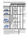
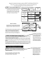
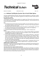
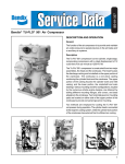
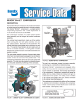
This troubleshooting guide obsoletes and supersedes all previous published
troubleshooting information relative to Bendix air compressors.
Advanced Troubleshooting Guide
for Air Brake Compressors
*
The guide consists of an introduction to air brake charging system
components, a table showing recommended vehicle maintenance
schedules, and a troubleshooting symptom and remedy section with tests
to diagnose most charging system problems.
INDEX
Symptom
Page Number
Air
Symptom
Page Number
Coolant
Air brake charging system:
Slow build (9.0) . . . . . . . . . . . . . . . . . . 9 - 10
Doesn’t build air (10.0) . . . . . . . . . . . . . . . 11
Air dryer:
Doesn’t purge (14.0) . . . . . . . . . . . . . . . . . 12
Safety valve releases air (12.0) . . . . . . . . . 12
Compressor:
Constantly cycles (15.0) . . . . . . . . . . . . . . 13
Leaks air (16.0) . . . . . . . . . . . . . . . . . . . . . 13
Safety valve releases air (11.0) . . . . . . . . . 11
Noisy (18.0) . . . . . . . . . . . . . . . . . . . . . . . . 13
Reservoir:
Safety valve releases air (13.0) . . . . . . . . . 12
Compressor leaks coolant (17.0) . . . . . . . . . . 13
Test Procedures
Maintenance & Usage Guidelines
(1) Oil Leakage at Head Gasket . . . 14
(2) System Leakage . . . . . . . . . . . . 14
Engine
Oil consumption (6.0) . . . . . . . . . . . . . . . . . . . . 9
Oil
Oil Test Card results (1.0) . . . . . . . . . . . . . . . . . 4
Oil is present:
On the outside of the compressor (2.0) . . . . 5
At the air dryer purge/exhaust
or surrounding area (3.0) . . . . . . . . . . . . 5
In the supply reservoir (4.0) . . . . . . . . . . 6 - 8
At the valves (5.0) . . . . . . . . . . . . . . . . . . . . 8
At air dryer cartridge (7.0) . . . . . . . . . . . . . . 9
In the ping tank or compressor
discharge aftercooler (8.0) . . . . . . . . . . . 9
Maintenance Schedule and
Usage Guidelines (Table A) . . . 3
(3) Compressor Discharge and
Air Dryer Inlet Temperature . . . . 14
(4) Governor Malfunction . . . . . . . . 14
(5) Governor Control Line . . . . . . . . 15
(6) Compressor Unloader . . . . . . . . 15
BASIC Test Information . . . . . . 17-20
*This guide is only for vehicles that use desiccant air dryers.
Introduction to the Air Brake Charging System
Powered by the vehicle engine, the air compressor
builds the air pressure for the air brake system. The
air compressor is typically cooled by the engine coolant
system and lubricated by the engine oil supply.
The compressor's unloader mechanism and governor
(along with a synchro valve for the Bendix® DuraFlo™
596 air compressor) control the brake system air
pressure between a preset maximum and minimum
pressure level by monitoring the pressure in the service
(or “supply”) reservoir. When the air pressure becomes
greater than that of the preset “cut-out”, the governor
controls the unloader mechanism of the compressor
to stop the compressor from building air and also
causes the air dryer to purge. As the service reservoir
air pressure drops to the “cut-in” setting of the governor,
the governor returns the compressor back to building
air and the air dryer to air drying mode.
As the atmospheric air is compressed, all the water
vapor originally in the air is carried along into the air
system, as well as a small amount of the lubricating oil
as vapor.
The duty cycle is the ratio of time the compressor
spends building air to the total engine running time.
Air compressors are designed to build air (run “loaded”)
up to 25% of the time. Higher duty cycles cause
conditions that affect air brake charging system
performance which may require additional
maintenance. Factors that add to the duty cycle are:
air suspension, additional air accessories, use of an
undersized compressor, frequent stops, excessive
leakage from fittings, connections, lines, chambers or
valves, etc.
The discharge line allows the air, water-vapor and
oil-vapor mixture to cool between the compressor and
air dryer. The typical size of a vehicle's discharge line,
(see column 2 of Table A on page 3) assumes a
compressor with a normal (less than 25%) duty cycle,
operating in a temperate climate. See Bendix and/or
other air dryer manufacturer guidelines as needed.
When the temperature of the compressed air that enters
the air dryer is within the normal range, the air dryer can
remove most of the charging system oil. If the
temperature of the compressed air is above the normal
range, oil as oil-vapor is able to pass through the air
dryer and into the air system. Larger diameter discharge
lines and/or longer discharge line lengths can help reduce
the temperature.
The discharge line must maintain a constant slope
down from the compressor to the air dryer inlet fitting
to avoid low points where ice may form and block the
flow. If, instead, ice blockages occur at the air dryer
inlet, insulation may be added here, or if the inlet fitting
is a typical 90 degree fitting, it may be changed to a
straight or 45 degree fitting. For more information on
how to help prevent discharge line freeze-ups, see
Bendix Bulletins TCH-08-21 and TCH-08-22 (see
pages 20-22). Shorter discharge line lengths or
insulation may be required in cold climates.
The air dryer contains a filter that collects oil droplets,
and a desiccant bed that removes almost all of the
remaining water vapor. The compressed air is then
passed to the air brake service (supply) reservoir. The
oil droplets and the water collected are automatically
purged when the governor reaches its “cut-out” setting.
For vehicles with accessories that are sensitive to small
amounts of oil, we recommended installation of a
Bendix® PuraGuard® system filter, designed to minimize
the amount of oil present.
The Air Brake Charging System supplies the
Discharge
Line
Optional “Ping” Tank
Air Dryer
compressed air for the braking system as well as other
air accessories for the vehicle. The system usually
consists of an air compressor, governor, discharge line,
air dryer, and service reservoir.
Optional Bendix® PuraGuard®
System Filter or PuraGuard®
QC™ Oil Coalescing Filter
Compressor
Governor
(Governor plus Synchro valve
for the Bendix® DuraFlo™ 596™
Compressor)
2
Service Reservoir
(Supply Reservoir)
Reservoir Drain
Table A: Maintenance Schedule and Usage Guidelines
Regularly scheduled maintenance is the single most important factor in maintaining the air brake charging system.
Vehicle Used for:
No. of
Axles
Column 1
Column 2
Typical
Compressors
Spec'd
Discharge
Line
I.D.
Length
1/2 in.
6 ft.
Column 3
Recommended
Air Dryer
Cartridge
Replacement1
Column 4
Recommended
Reservoir
Drain
Schedule2
Column 5
Acceptable
Reservoir
Oil Contents3
at Regular
Drain Interval
e.g. Line haul single trailer
w/o air suspension, air over
hydraulic brakes.
5
or
less
e.g. Line haul single trailer
with air suspension,
school bus.
5
or
less
High Air Use
e.g. Double/triple trailer, open
highway coach/RV, (most)
pick-up & delivery, yard or
terminal jockey, off-highway,
construction, loggers, concrete
mixer, dump truck, fire truck.
8
or
less
Compressor with up to 25% duty cycle
e.g. City transit bus, refuse,
bulk unloaders, low boys,
urban region coach, central
tire inflation.
12
or
less
Bendix® Tu-Flo® 750 air compressor
Compressor with up to 25% duty cycle
Bendix® BA-921™ air compressor
Compressor with up to 25% duty cycle
For oil carry-over
control4 suggested
upgrades:
5/8 in.
1/2 in.
9 ft.
9 ft.
Every 3
Years
For oil carry-over
control4 suggested
upgrades:
5/8 in.
1/2 in.
5/8 in.
Recommended
Every
Month Max of
every 90
days
12 ft.
For the
BASIC
Test Kit:
Order
Bendix
P/N
5013711
Every 2
Years
15 ft.
Every
Month
5/8 in.
12 ft.
For oil carry-over
control4 suggested
upgrades:
3/4 in.
BASIC test
acceptable
range:
5 oil units
per month.
See
appendix
A.
Every
Year
15 ft.
Footnotes:
1 With increased air demand the air dryer cartridge needs to be replaced more often.
2 Use the drain valves to slowly drain all reservoirs to zero psi.
3 Allow the oil/water mixture to fully settle before measuring oil quantity.
4 To counter above normal temperatures at the air dryer inlet, (and resultant oil-vapor passing
upstream in the air system) replace the discharge line with one of a larger diameter and/
or longer length. This helps reduce the air's temperature. If sufficient cooling occurs, the
oil-vapor condenses and can be removed by the air dryer. Discharge line upgrades are not
covered under warranty. Note: To help prevent discharge line freeze-ups, shorter discharge
line lengths or insulation may be required in cold climates. (See Bendix Bulletins TCH-08-21
and TCH-08-22, included in Appendix B, for more information.)
5 For certain vehicles/applications, where turbo-charged inlet air is used, a smaller size
compressor may be permissible.
3
BASIC test
acceptable
range:
3 oil units
per month.
See
appendix
A.
12 ft.
For oil carry-over
control4 suggested
upgrades:
Bendix® BA-922™, or DuraFlo™ 596 air compressor
Compressor with less than 15% duty
cycle
Bendix® Tu-Flo® 550 air compressor
Low Air Use
Note: Compressor and/or air dryer
upgrades are recommended in cases
where duty cycle is greater than the
normal range (for the examples
above).
For Bendix® Tu-Flo® 550 and 750
compressors, unloader service is
recommended every 250,000 miles.
Air Brake Charging System Troubleshooting
How to use this guide:
Find the symptom(s) that you see, then move to the right to
find the possible causes (“What it may indicate”) and
remedies (“What you should do”).
Review the warranty policy before performing any intrusive
compressor maintenance. Unloader or cylinder head gasket
replacement and resealing of the bottom cover plate are
usually permitted under warranty. Follow all standard safety
procedures when performing any maintenance.
WARNING! Please READ and follow these instructions to
avoid personal injury or death:
When working on or around a vehicle, the following general
precautions should be observed at all times.
1. Park the vehicle on a level surface, apply the parking
brakes, and always block the wheels. Always wear safety
glasses.
2. Stop the engine and remove ignition key when working
under or around the vehicle. When working in the engine
compartment, the engine should be shut off and the ignition
key should be removed. Where circumstances require that
the engine be in operation, EXTREME CAUTION should
be used to prevent personal injury resulting from contact
with moving, rotating, leaking, heated or electrically charged
components.
3. Do not attempt to install, remove, disassemble or assemble
a component until you have read and thoroughly
understand the recommended procedures. Use only the
proper tools and observe all precautions pertaining to use
of those tools.
4. If the work is being performed on the vehicle’s air brake
system, or any auxiliary pressurized air systems, make
certain to drain the air pressure from all reservoirs before
beginning ANY work on the vehicle. If the vehicle is
equipped with an AD-IS™ air dryer system or a dryer
reservoir module, be sure to drain the purge reservoir.
Symptom:
1.0 Oil Test Card
Results
Look for:
Normal - Charging system is working within
normal range.
Check - Charging system needs further
investigation.
5. Following the vehicle manufacturer’s recommended
procedures, deactivate the electrical system in a manner
that safely removes all electrical power from the vehicle.
6. Never exceed manufacturer’s recommended pressures.
7. Never connect or disconnect a hose or line containing
pressure; it may whip. Never remove a component or plug
unless you are certain all system pressure has been
depleted.
8. Use only genuine Bendix® replacement parts, components
and kits. Replacement hardware, tubing, hose, fittings, etc.
must be of equivalent size, type and strength as original
equipment and be designed specifically for such
applications and systems.
9. Components with stripped threads or damaged parts
should be replaced rather than repaired. Do not attempt
repairs requiring machining or welding unless specifically
stated and approved by the vehicle and component
manufacturer.
10. Prior to returning the vehicle to service, make certain all
components and systems are restored to their proper
operating condition.
11. For vehicles with Antilock Traction Control (ATC), the ATC
function must be disabled (ATC indicator lamp should be
ON) prior to performing any vehicle maintenance where
one or more wheels on a drive axle are lifted off the ground
and moving.
What it may indicate:
What you should do:
Not a valid test.
Discontinue using this test.
Do not use this card test to diagnose
compressor "oil passing" issues. They are
subjective and error prone. Use only the
Bendix Air System Inspection Cup (BASIC) test
and the methods described in this guide for
advanced troubleshooting.
The Bendix ® BASIC test should be the
definitive method for judging excessive oil
fouling/oil passing. (See Appendix A, on
page 17 for a flowchart and expanded
explanation of the checklist used when
conducting the BASIC test.)
û
Bendix®
BASIC Test
ü
4
Symptom:
What it may indicate:
What you should do:
2.0 Oil on the
Outside of the
Compressor
Engine and/or other accessories
leaking onto compressor.
Find the source and repair. Return the vehicle
to service.
2.1 Oil leaking at
compressor / engine
connections:
(a)Leak at the front or rear (fuel
pump, etc.) mounting flange.
ð Repair or replace as necessary. If the
mounting bolt torques are low, replace the
gasket.
(b)Leak at air inlet fitting.
ð Replace the fitting gasket. Inspect inlet
hose and replace as necessary.
(c)Leak at air discharge fitting.
ð Replace gasket or fitting as necessary to
ensure good seal.
(d)Loose/broken oil line fittings.
ð Inspect and repair as necessary.
(a)Excessive leak at head gasket.
ð Go to Test 1 on page 14.
(b)Leak at bottom cover plate.
ð Reseal bottom cover plate using RTV
silicone sealant.
(c)Leak at internal rear flange gasket.
ð Replace compressor.
(d)Leak through crankcase.
ð Replace compressor.
(e)(If unable to tell source of leak.)
ð Clean compressor and check periodically.
2.2 Oil leaking
from compressor:
ð
(c)
(a)
ð
(c)
3.0 Oil at air dryer
purge/exhaust or
surrounding area
Head
gasket
and rear
flange
gasket
locations.
Air brake charging system functioning
normally.
5
ð Air dryers remove water and oil from the
air brake charging system.
Check that regular maintenance is being
performed. Return the vehicle to service.
An optional kit (Bendix piece number
5011327 for the Bendix® AD-IS™ or AD-IP™
air dryers, or 5003838 for the Bendix®
AD-9™ air dryer) is available to redirect the
air dryer exhaust.
Symptom:
What it may indicate:
4.0 Oil in Supply or
Service Reservoir
(air dryer installed)
(If a maintained Bendix
PuraGuard™ system
filter or Bendix®
PuraGuard® QC™ oil
coalescing filter is
installed, call
1-800-AIR-BRAKE
(1-800-247-2725) and
speak to a Tech Team
member.)
®
What you should do:
Maintenance
(a) If air brake charging system
maintenance has not been
performed.
That is, reservoir(s) have not been
drained per the schedule in Table
A on page 3, Column 4 and/or the
air dryer maintenance has not
been performed as in Column 3.
ð Drain all air tanks and check vehicle at next
service interval using the Bendix® BASIC
test. See Table A on page 3, column 3
and 4, for recommended service schedule.
(b) If the vehicle maintenance has
been performed as recommended in Table A on page 3,
some oil in the reservoirs is normal.
ð Drain all air tanks into Bendix® BASIC test
cup (Bendix Air System Inspection Cup).
If less than one unit of reservoir contents
is found, the vehicle can be returned to
service. Note: If more than one oil unit
of water (or a cloudy emulsion mixture)
is present, change the vehicle's air
dryer, check for air system leakage (Test
2, on page 14), stop inspection and
check again at the next service interval.
See the BASIC test kit for full details.
If less than one "oil unit" of water (or water/
cloudy emulsion mixture) is present, use
the BASIC cup chart on the label of the
cup to determine if the amount of oil found
is within the acceptable level.
ðIf within the normal range, return the
vehicle to service. For vehicles with
accessories that are sensitive to small
amounts of oil, consider a Bendix ®
PuraGuard® QC™ oil coalescing filter.
ð If outside the normal range go to
Symptom 4.0(c).
Also see the Table A on page 3, column 3
for recommended air dryer cartridge
replacement schedule.
(a)
See Table A, on page 3,
for maintenance
schedule information.
Drain all air tanks (reservoirs)
into the Bendix® BASIC test
cup. (Bendix kit P/N 5013711).
Duty cycle too high
(c) Air brake system leakage.
ð Go to Test 2 on page 14.
(d) Compressor may be undersized for
the application.
ð See Table A, column 1, on page 3 for
recommended compressor sizes.
ð If the compressor is "too small" for
the vehicle's role (for example, where a
vehicle's use has changed or service
conditions exceed the original vehicle or
engine OE spec's) then upgrade the
compressor. Note: The costs incurred (e.g.
installing a larger capacity compressor,
etc.) are not covered under original
compressor warranty.
ð If the compressor is correct for the
vehicle, go to Symptom 4.0 (e).
The duty cycle is the ratio of time the compressor spends
building air to total engine running time. Air compressors
are designed to build air (to "run loaded") up to 25% of the
time. Higher duty cycles cause conditions that affect air
brake charging system performance which may require
additional maintenance. Factors that add to the duty cycle
are: air suspension, additional air accessories, use of an
undersized compressor, frequent stops, excessive leakage
from fittings, connections, lines, chambers or valves, etc.
6
Symptom:
What it may indicate:
4.0 Oil in Supply
or Service
Reservoir*
(air dryer installed)
(continued)
What you should do:
Temperature
(e) Air compressor discharge and/or
air dryer inlet temperature too high.
ð Check temperature as outlined in Test 3
on page 14. If temperatures are normal
go to 4.0(h).
(f) Insufficient coolant flow.
ð Inspect coolant line. Replace as necessary
(I.D. is 1/2").
ð Inspect the coolant lines for kinks and
restrictions and fittings for restrictions.
Replace as necessary.
(f)
(e)
ð Verify coolant lines go from engine block
to compressor and back to the water pump.
Repair as necessary.
(g)
Testing the temperature
at the discharge fitting.
Inspecting the coolant hoses.
(g) Restricted discharge line.
(g)
ð If discharge line is restricted or more than
1/16" carbon build up is found, replace the
discharge line. See Table A, column 2, on
page 3 for recommended size. Replace as
necessary.
ð The discharge line must maintain a
constant slope down from the compressor
to the air dryer inlet fitting to avoid low
points where ice may form and block the
flow. If, instead, ice blockages occur at the
air dryer inlet, insulation may be added
here, or if the inlet fitting is a typical 90
degree fitting, it may be changed to a
straight or 45 degree fitting. For more
information on how to help prevent discharge
line freeze-ups, see Bendix Bulletins
TCH-08-21 and TCH-08-22 (Appendix B).
Shorter discharge line lengths or insulation
may be required in cold climates.
Kinked discharge line shown.
Other
(h) Restricted air inlet (not enough air
to compressor).
(h)
ð Check compressor air inlet line for
restrictions, brittleness, soft or sagging
hose conditions etc. Repair as necessary.
Inlet line size is 3/4 ID. Maximum
restriction requirement for compressors is
25 inches of water.
ð Check the engine air filter and service if
necessary (if possible, check the air filter
usage indicator).
Partly
collapsed
inlet line
shown.
*If a maintained Bendix® PuraGuard™ system filter or Bendix® PuraGuard® QC™ oil coalescing
filter is installed, call 1-800-AIR-BRAKE (1-800-247-2725) and speak to a Tech Team
member.
7
Symptom:
4.0 Oil in Supply
or Service
Reservoir*
(air dryer installed)
(continued)
What it may indicate:
What you should do:
Other (cont.)
(i) Poorly filtered inlet air (poor air
quality to compressor).
Inspect the
engine air
cleaner.
ð Check for leaking, damaged or defective
compressor air inlet components (e.g.
induction line, fittings, gaskets, filter bodies,
etc.). Repair inlet components as needed.
Note: Dirt ingestion will damage
compressor and is not covered under
warranty.
(j) Governor malfunction or setting.
ð Go to Test 4 on page 15.
(k) Compressor malfunction.
ð If you found excessive oil present in the
service reservoir in step 4.0 (b) above and
you did not find any issues in steps 4.0 (c)
through 4.0 (j) above, the compressor may
be passing oil.
Replace compressor. If still under
warranty, follow normal warranty process.
Note: After replacing a compressor,
residual oil may take a considerable period
of time to be flushed from the air brake
system.
Crankcase Flooding
Consider installing a compressor bottom drain kit
(where available) in cases of chronic oil passing
where all other operating conditions have been
investigated. Bendix compressors are designed to
have a 'dry' sump and the presence of excess oil in
the crankcase can lead to oil carryover.
*If a maintained Bendix® PuraGuard™ system filter or Bendix® PuraGuard® QC™ oil coalescing
filter is installed, call 1-800-AIR-BRAKE (1-800-247-2725) and speak to a Tech Team member.
5.0 Oil present at
valves (e.g. at
exhaust, or seen
during servicing).
Air brake system valves are required
to tolerate a light coating of oil.
ð A small amount of oil does not affect SAE
J2024** compliant valves.
ð Check that regular maintenance is being
performed and that the amount of oil in the
air tanks (reservoirs) is within the
acceptable range shown on the Bendix®
BASIC test cup (see also column 5 of Table
A on page 3). Return the vehicle to service.
For oil-sensitive systems, see page 2.
** SAE J2024 outlines tests all air brake system pneumatic
components need to be able to pass, including minimum
levels of tolerance to contamination.
Genuine
Bendix
valves are
all SAE
J2024
compliant.
8
Symptom:
What it may indicate:
What you should do:
6.0 Excessive oil
consumption in
engine.
A problem with engine or other engine
accessory.
ð See engine service manual.
7.0 Oil present at
air dryer cartridge
during
maintenance.
Air brake charging system is
functioning normally.
The engine
service
manual has
more
information.
Oil shown
leaking
from an air
dryer
cartridge.
ð Air dryers remove water and oil from the air
brake charging system. A small amount of
oil is normal. Check that regular
maintenance is being performed and that
the amount of oil in the air tanks
(reservoirs) is within the acceptable range
shown by the BASIC Test (see also column
5 of Table A on page 3). Replace the air
dryer cartridge as needed and return the
vehicle to service.
8.0 Oil in ping tank
or compressor discharge aftercooler.
Air brake charging system is
functioning normally.
ð Follow vehicle O.E. maintenance
recommendation for these components.
9.0 Air brake
charging system
seems slow to
build pressure.
(a) Air brake charging
functioning normally.
ð Using dash gauges, verify that the
compressor builds air system pressure
from 85-100 psi in 40 seconds or less with
engine at full governed rpm. Return the
vehicle to service.
system
(b) Air brake system leakage.
ð Go to Test 2 on page 14.
(c) Compressor may be undersized for
the application.
ð See Table A, column 1, on page 3 for some
typical compressor applications. If the
compressor is "too small" for the vehicle's
role, for example, where a vehicle's use
has changed, then upgrade the
compressor. Note: The costs incurred
(e.g. installing a larger capacity
compressor, etc.) are not covered under
original compressor warranty.
(d) Compressor unloader mechanism
malfunction.
ð Go to Test 6 on page 15.
(e) Damaged
gasket.
ð An air leak at the head gasket may indicate
a downstream restriction such as a
freeze-up or carbon blockage and/or could
indicate a defective or missing safety
valve. Find blockage (go to 9.0(f) for
details.) and then replace the compressor.
Do not re-use the safety valve without
testing. See Symptom 12.0(a).
compressor
head
9
Symptom:
9.0 Air brake
charging system
seems slow to
build pressure.
(continued)
What it may indicate:
What you should do:
(f) Restricted discharge line.
ð If discharge line is restricted:
ð By more than 1/16" carbon build up,
replace the discharge line (see Table A,
column 2, on page 3 for recommended
size) and go to Test 3 on page 14.
ð By other restrictions (e.g. kinks).
Replace the discharge line. See Table A,
column 2, on page 3 for recommended
size. Retest for air build. Return vehicle to
service or, if problem persists, go to 9.0(a).
(f)
Dash gauges.
(g)
Kinked discharge line shown.
(g) Restricted air inlet (not enough air
to compressor).
ð The discharge line must maintain a
constant slope down from the compressor
to the air dryer inlet fitting to avoid low points
where ice may form and block the flow. If,
instead, ice blockages occur at the air dryer
inlet, insulation may be added here, or if
the inlet fitting is a typical 90 degree fitting,
it may be changed to a straight or 45 degree
fitting. For more information on how to help
prevent discharge line freeze-ups, see
Bendix Bulletins TCH-08-21 and
TCH-08-22 (Appendix B).
Shorter
discharge line lengths or insulation may be
required in cold climates.
ð Check compressor air inlet line for
restrictions, brittleness, soft or sagging
hose conditions etc. Repair as necessary.
Refer to vehicle manufacturer’s guidelines
for inlet line size.
ð Check the engine air filter and service if
necessary (if possible, check the air filter
usage indicator).
Partly collapsed
inlet line shown.
(h) Poorly filtered inlet air (poor air
quality to compressor).
ð Check for leaking, damaged or defective
compressor air inlet components (e.g.
induction line, fittings, gaskets, filter
bodies, etc.). Repair inlet components as
needed. Note: Dirt ingestion will damage
compressor and is not covered under
warranty.
(i) Compressor malfunction.
ð Replace the compressor only after making
certain that none of the preceding
conditions, 9.0 (a) through 9.0 (h), exist.
10
Symptom:
10.0 Air charging
system doesn’t
build air.
What it may indicate:
What you should do:
(a) Governor malfunction*.
ð Go to Test 4 on page 15.
(b) Restricted discharge line.
ð See 9.0(f).
(c) Air dryer heater malfunction:
exhaust port frozen open.
ð Replace air dryer heater.
(d) Compressor malfunction.
ð Replace the compressor only after making
certain the preceding conditions do not
exist.
* Note: For the Bendix® DuraFlo™ 596 air compressor, not only
the governor, but also the SV-1™ synchro valve used would
need to be tested. See Bulletin TCH-001-048.
11.0 Compressor
safety valve
releases air
(Compressor
builds too much
air).
(a) Restricted discharge line.
ð If discharge line is restricted:
ð By more than 1/16" carbon build up,
replace the discharge line (see Table A,
column 2, on page 3 for recommended
size) and go to Test 3 on page 14.
ð By other restrictions (e.g. kinks).
Replace the discharge line. See Table A,
column 2, on page 3 for recommended
size.
ð
ð The discharge line must maintain a
constant slope down from the compressor
to the air dryer inlet fitting to avoid low
points where ice may form and block the
flow. If, instead, ice blockages occur at the
air dryer inlet, insulation may be added
here, or if the inlet fitting is a typical 90
degree fitting, it may be changed to a
straight or 45 degree fitting. For more
information on how to help prevent discharge
line freeze-ups, see Bendix Bulletins TCH08-21 and TCH-08-22 (Appendix B).
Shorter discharge line lengths or insulation
may be required in cold climates.
Damaged
discharge
line
shown.
(b) Downstream air brake system
check valves or lines may be
blocked or damaged.
ð Inspect air lines and verify check valves
are operating properly.
(c) Air dryer lines incorrectly installed.
ð Ensure discharge line is installed into the
inlet of the air dryer and delivery is routed
to the service reservoir.
(d) Compressor safety valve
malfunction.
ð Verify relief pressure is 250 psi. Replace
if defective.
(e) Compressor unloader mechanism
malfunction.
ð Go to Test 6 on page 15.
(f) Governor malfunction.
ð Go to Test 4 on page 15.
11
Symptom:
12.0 Air dryer
safety valve
releases air.
What it may indicate:
What you should do:
(a) Restriction between air dryer and
reservoir.
ð Inspect delivery lines to reservoir for
restrictions and repair as needed.
(b) Air dryer safety valve malfunction.
ð Verify relief pressure is at vehicle or
component manufacturer specifications.
Replace if defective.
(c) Air dryer
performed.
ð See Maintenance Schedule and Usage
Guidelines (Table A, column 3, on page
3).
Air dryer
safety valve
ð
ê
ê
Technician removes
governor.
13.0 Reservoir
safety valve
releases air
14.0 Air dryer
doesn’t purge.
(Never hear
exhaust from air
dryer.)
15.0 Compressor
constantly cycles
(compressor
remains unloaded
for a very short
time.)
maintenance
not
(d) Air dryer malfunction.
ð Verify operation of air dryer. Follow vehicle
O.E. maintenance recommendations and
component Service Data information.
(e) Improper governor control line
installation to the reservoir.
ð Go to Test 5 on page 15.
(f) Governor malfunction.
ð Go to Test 4 on page 15.
(a) Reservoir safety valve malfunction.
ð Verify relief pressure is at vehicle or
component manufacturer's specifications
(typically 150 psi). Replace if defective.
(b) Governor malfunction.
ð Go to Test 4 on page 15.
(c) Compressor unloader mechanism
malfunction.
ð Go to Test 6 on page 15.
(a) Air dryer malfunction.
ð Verify operation of air dryer. Follow vehicle
O.E. maintenance recommendations.
(b) Governor malfunction.
ð Go to Test 4 on page 15.
(c) Air brake system leakage.
ð Go to Test 2 on page 14.
(d) Improper governor control line
installation to the reservoir.
ð Go to Test 5 on page 15.
(a) Air brake charging system
maintenance not performed.
ð Available reservoir capacity may be
reduced by build up of water etc. Drain
and perform routine maintenance per
Table A, columns 3 & 4, on page 3.
(b) Compressor unloader mechanism
malfunction.
ð Go to Test 6 on page 15.
(c) Air dryer purge valve or delivery
check valve malfunction.
ð Verify operation of air dryer. Follow vehicle
O.E. maintenance recommendations and
component Service Data information.
(d) Air brake system leakage.
ð Go to Test 2 on page 14.
12
Symptom:
16.0 Compressor
leaks air
What it may indicate:
(a) Compressor leaks
connections or ports.
at
ð Check for leaking, damaged or defective
compressor fittings, gaskets, etc. Repair
or replace as necessary.
ð Go to Test 6 on page 15.
(c) Damaged
gasket.
head
ð An air leak at the head gasket may indicate
a downstream restriction such as a freezeup or carbon blockage and/or could
indicate a defective or missing safety
valve. Find blockage (go to 9.0(f) for
details.) and then replace the compressor.
Do not re-use the safety valve without
testing. See Symptom 12.0(a).
(a) Improperly installed plugs or
coolant line fittings.
ð Inspect for loose or over-torqued fittings.
Reseal and tighten loose fittings and plugs
as necessary. If overtorqued fittings and
plugs have cracked ports in the head,
replace the compressor.
(b) Damaged
gasket.
head
ð An air leak at the head gasket may indicate
a downstream restriction such as a freezeup or carbon blockage and/or could
indicate a defective or missing safety
valve. Find blockage (go to 9.0(f) for
details.) and then replace the compressor.
Do not re-use the safety valve without
testing. See Symptom 12.0(a).
(c) Porous compressor head casting.
ð If casting porosity is detected, replace the
compressor.
(a) Damaged compressor.
ð Replace the compressor.
compressor
Head
gasket
location
ð
18.0 Noisy
compressor
(Multi-cylinder
compressors only)
air
(b) Compressor unloader mechanism
malfunction.
Testing for leaks
with soap solution.
17.0 Compressor
leaks coolant
What you should do:
compressor
Other Miscellaneous Areas to Consider
This guide attempts to cover most
compressor system problems. Here are
some rare sources of problems not
covered in this guide:
• Turbocharger leakage. Lubricating oil
from leaking turbocharger seals can enter
the air compressor intake and give
misleading symptoms.
• Where a compressor does not have a
safety valve installed, if a partial or
complete discharge line blockage has
occurred, damage can occur to the
connecting rod bearings. Damage of this
kind may not be detected and could lead
to compressor problems at a later date.
13
Tests
Test 1: Excessive Oil Leakage at the
Head Gasket
Exterior leaks at the head gasket are not a sign that oil is being passed
into the air charging system. Oil weepage at the head gasket does not
prevent the compressor from building air.
Observe the amount of weepage from the head gasket.
If the oil is only around the cylinder head area, it is acceptable (return the
vehicle to service), but, if the oil weepage extends down to the nameplate area
of the compressor, the gasket can be replaced.
LOOK
FOR
WEEPAGE
Test 2: Air Brake System and Accessory Leakage
Inspect for air leaks when working on a vehicle and
repair them promptly.
Park the vehicle on level ground and chock wheels.
Build system pressure to governor cut-out and allow
the pressure to stabilize for one minute.
Step 1: Observe the dash gauges for two additional
minutes without the service brakes applied.
Step 2: Apply the service brakes and allow the
pressure to stabilize. Continue holding for two
minutes (you may use a block of wood to hold the
pedal in position.) Observe the dash gauges.
If you see any noticeable decrease of the dash air
gauge readings (i.e. more than 4 psi, plus two psi
for each additional trailer) during either two minute
test, repair the leaks and repeat this test to confirm
that they have been repaired.
Air leaks can also be found in the charging system,
parking brakes, and/or other components - inspect
and repair as necessary.
Test 3: Air Compressor Discharge
Temperature and Air Dryer Inlet
Temperature*
Note: The temperatures used in this test are
not normal vehicle conditions.
Above normal temperatures can cause oil (as
vapor) to pass through the air dryer into the
air brake system.
This test is run with the engine at normal
operating temperature, with engine at max. rpm.
If available, a dyno may be used.
1. Allow the compressor to build the air system
pressure to governor cut-in.
2. Pump the brakes to bring the dash gauge
pressure to 90 psi.
3. Allow the compressor to build pressure from
95 to 105 psi gauge pressure and maintain
this pressure range by cycling the brakes for
five (5) minutes.
(* Note that only vehicles that have passed Test 2
would be candidates for this test.)
4. Then, while maintaining max rpm and
pressure range, measure and record the
surface temperature of the fittings:
ð at the compressor discharge port. (T1).
ð at the air dryer inlet fitting. (T2).
Use a touch probe thermocouple for
measuring the temperature.
5. See table below.
6. Retest before returning the vehicle to service.
T1
T2
Compressor Air Dryer
Discharge
Inlet
Fitting
Fitting
under
360°F
under
200°F
Temperatures are within
normal range for this test, check
other symptoms. Go to 4.0 (h).
under
360°F
over
200°F
This could indicate a discharge
line problem (e.g. restriction).
Call 1-800-AIR-BRAKE
(1-800-247-2725)
and speak with our Tech Team.
over
360°F
__
T1
T2
Discharge Line
14
Action
Compressor is running hot.
Check coolant 4(f) and/or
discharge line 4(g).
Tests (continued)
Test 4: Governor Malfunction
reservoir, service reservoir, or reservoir port
of the D-2™ governor, verify cut-in and cutout pressures are within vehicle OEM
specification.
3. If the governor is malfunctioning, replace it.
1. Inspect control lines to and from the governor
for restrictions (e.g. collapsed or kinked).
Repair as necessary.
2. Using a calibrated external gauge in the supply
Test 5: Governor Control Line
2. Perform proper reservoir drain intervals and
air dryer cartridge maintenance per
Maintenance Schedule and Usage Guidelines
(Table A on page 3).
3. Return the vehicle to service.
1. Ensure that the governor control line from the
reservoir is located at or near the top of the
reservoir. (This line, if located near the bottom
of the reservoir, can become blocked or
restricted by the reservoir contents e.g. water
or ice.)
Test 6: Compressor Unloader Leakage
off and charge the unloader port by allowing air
pressure to enter the hose and unload the
compressor. Shut off the air supply and observe
the gauge. A steady reading indicates no leakage
at the unloader port, but a falling reading shows
that the unloader mechanism is leaking and needs
to be serviced.
Bendix ® Compressors: Park vehicle, chock
wheels, and follow all standard safety procedures.
Remove the governor and install a fitting to the
unloader port. Add a section of air hose (min 1ft
long for a 1/2" diameter line) and a gauge to the
fitting followed by a shut-off valve and an air
source (shop air or small air tank). Open the shut
15
NOTES
16
Appendix A: Information about the BASIC Test Kit (Bendix P/N 5013711)
Service writer records info - including
the number of days since all air tanks
were drained - and fills out symptom
checklist. Technician inspects items.
days
Bendix® Air System Inspection Cup
(BASIC) Test Information
START BASIC TEST
Park vehicle on LEVEL ground.
Chock wheels, drain air from system.
Drain contents of ALL air
tanks into BASIC cup
Is there
less than one
unit of liquid?
Vehicle OK.
Return vehicle to
service.
YES
END TEST
NO
Is
there more
than one unit of:
• water, or
• cloudy emulsion
mixture?
Cloudy emulsion mixture
YES
NO, only oil.
Is this a
transit vehicle, bulk
unloader, or has more
than 5 axles?
YES, this is a high
air use
vehicle.
Hig
Find the point on the label
where the number of oil units
meets the number of days*
since the vehicle's air tanks
were last drained.
h
Low
Hig
Is the
point above
the HIGH Air Use
line on the
cup?
H
NO, this is a low air
use vehicle.
Find the point on the label
where the number of oil units
meets the number of days*
since the vehicle's air tanks
were last drained.
h
Is the
point above
the LOW Air Use
line on the
cup?
NO
YES
Test for air
leakage
Low
END TEST
Does
the vehicle have
excessive air
leakage?
YES
Change air dryer
cartridge**
Test for air
leakage
Use Test 2:
Air Leakage
Re-test with the
BASIC Test after
30 days***
END TEST
Vehicle OK.
Return vehicle to
service.
Repair leaks and
return vehicle to
service
NO (did not know
when last
drained) Re-test with the
BASIC Test after
30 days***
END TEST
* If the number of days since the air tanks were drained is
unknown - use the 30 day line.
END TEST
** Note: Typical air dryer cartridge replacement schedule is every
3 yrs/ 300K miles for low air use vehicles and every year/100K
miles for high air use vehicles.
NO
Was
the number of
days since last
draining
known?
NO
Low
YES
Use Test 2:
Air Leakage
Is this vehicle
being re-tested (after
water, etc. was found
last time?)
Go to the
Advanced
Troubleshooting
Guide to find
reason(s) for
presence of water
NO
igh
*** To get an accurate reading for the amount of oil collected
during a 30 day period, ask the customer not to drain the air
tanks before returning. (Note that 30-90 days is the
recommended air tank drain schedule for vehicles equipped
with a Bendix air dryer that are properly maintained.) If, in cold
weather conditions, the 30 day air tank drain schedule is longer
than the customer's usual draining interval, the customer must
determine, based on its experience with the vehicle, whether to
participate now, or wait for warmer weather. See the cold
weather tips in Bulletins TCH-008-21 and TCH-008-22 (included
on pages 20-22 of this document).
END TEST
YES, number of days
was known (30 - 90 days)
Compressor
YES
Replace the Compressor. If under warranty, follow standard
procedures.
If, after a compressor was already replaced, the vehicle fails the
BASIC test again, do not replace the compressor**** - use the
Advanced Troubleshooting Guide to investigate the cause(s).
****Note: After replacing a compressor, residual oil may take a
considerable period of time to be flushed from the air brake system.
END TEST
17
Appendix A continued: Information about the BASIC Test Kit (Bendix P/N 5013711)
®
Filling in the Checklist for the Bendix Air System Inspection Cup (BASIC) Test
Note: Follow all standard safety precautions. For vehicles using a desiccant air dryer.
The Service Writer fills out these fields with information gained from the customer
Number of Days Since Air Tanks Were Last Drained: ________ Date: ___________Vehicle #: ____________
Engine SN __________________________ Vehicle Used for: _______________Typical Load:________ (lbs.)
No. of Axles: ____ (tractor) ____ (trailer) No. of Lift Axles: ____ Technician’s Name: ____________________
Checklist for Technician
The Service Writer
also checks off any
complaints that the
customer makes to
help the Technician
in investigating.
Have you confirmed complaint?
è
Customer’s Complaint
(Please check all that apply)
“Relay valve q leaks oil / q malfunctions” . . . . . . . q no q yes*
“Dash valve q leaks oil / q malfunctions” . . . . . . . q no q yes*
q “Air dryer leaks oil” . . . . . . . . . . . . . . . . . . . . . . . q no q yes*
q “Governor malfunction” . . . . . . . . . . . . . . . . . . . . q no q yes*
q “Oil in gladhands” . . . . . . . . . . . . . . . . . . . . . . . . q no q yes*
how much oil did you find? ________________________________
q “Oil on ground or vehicle exterior” . . . . . . . . . . . q no q yes*
amount described: ______________________________________
q “Short air dryer cartridge life”
replaces every: ______________ q miles, q kms, or q months
q “Oil in air tanks” amount described:_______________________
We will measure amount currently found when we get to step B of the test.
q “Excessive engine oil loss” amount described: ______________
Is the engine leaking oil? . . . . . . . . . . . . . . . . . . . . . q no q yes*
Is the compressor leaking oil? . . . . . . . . . . . . . . . . . q no q yes*
q Other complaint:
______________________________________
q No customer complaint.
BASIC test starts here:
STEP A - Select one:
q This is a low air use vehicle: Line haul (single trailer) with 5 or less axles, or
q This is a high air use vehicle: Garbage truck, transit bus, bulk unloader, or
line haul with 6 or more axles.
Then go to Step B.
STEP B - Measure the Charging System Contents
1. Park and chock vehicle on level ground. Drain the air system by
pumping the service brakes.
2. Completely drain ALL the air tanks into a single BASIC cup.
3. If there is less than one unit of contents total, end the test now and
return the vehicle to service. Vehicle passes.
4. If more than one oil unit of water (or a cloudy emulsion mixture)
is found:
(a) Change the vehicle’s air dryer cartridge
Oil
- see Footnote 1,
Units
(b) Conduct the 4 minute leakage test (Step D),
(c) STOP the inspection, and check the vehicle
again after 30 days - see Footnote 2. STOP
Otherwise, go to Step C.
+ CK.
The Technician
checks boxes for
any of the
complaints that
can be confirmed.
* Note: A confirmed complaint above does NOT mean
that the compressor must be
replaced.
The full BASIC test below will
investigate the facts.
The Technician selects the air use
category for the vehicle. This
decided which of the two acceptance lines on the cup will be used
for the test below.
For an accurate test, the
contents of all the air tanks on
the vehicle should be used.
Note for returning vehicles that are being
retested after a water/cloudy emulsion
mixture was found last time and the air
dryer cartridge replaced: If more than one
oil unit of water or a cloudy emulsion mixture
is found again, stop the BASIC test and
consult the air dryer's Service Data sheet
troubleshooting section.
Footnote 1: Note: Typical air dryer cartridge replacement schedule is every 3 yrs/ 300K miles for low air use vehicles and every year/100K miles for
high air use vehicles.
Footnote 2: To get an accurate reading for the amount of oil collected during a 30 day period, ask the customer not to drain the air tanks before
returning. (Note that 30-90 days is the recommended air tank drain schedule for vehicles equipped with a Bendix air dryer that are properly
maintained.) If, in cold weather conditions, the 30 day air tank drain schedule is longer than the customer's usual draining interval, the customer
must determine, based on its experience with the vehicle, whether to participate now, or wait for warmer weather. See the cold weather tips in
Bulletins TCH-008-21 and TCH-008-22 (included in Appendix B of the advanced troubleshooting guide).
18
Appendix A continued: Information about the BASIC Test Kit (Bendix P/N 5013711)
®
Filling in the Checklist for the Bendix Air System Inspection Cup (BASIC) Test
Note: Follow all standard safety precautions. For vehicles using a desiccant air dryer.
2. Record amount
of oil found:
The Technician uses the chart (label) on the BASIC
test cup to help decide the action to take, based
on the amount of oil found. Use the lower
acceptance line for low air use vehicles, and upper
line for high air use vehicles (from Step A).
_________ days
_________ units
3. Action to
take
è
è
1. Record days since air
tanks were last drained.
è
STEP C - How to Use the BASIC Test
if oil level is at or below System OK.
STOP
If number of days is:
acceptance line for number
TEST
30-60 days (high air
Return
to
service.
of daysè
use) or
if oil level is above
30-90 days (low air use)
Go to Step D
acceptance line for number
è
of days è
if oil level is at or below System OK.
STOP
TEST
30-day acceptance line è
Return to service.
Stop inspection.
(if the number of days is
STOP
unknown, or outside the if oil level is above 30-day Test again
acceptance
line
è
after 30 days. + CK.
limits above)
See Footnote 2.
Otherwise . . .
è
Acceptance
Lines
BASIC Test Example
An oil level of 4 units in a sixty-day period is within the
acceptance area (at or below the line) for both low
and high air use vehicles. Return the vehicle to service.
The Technician looks for the point where the number
of days since the air tanks were drained meets the
oil level. If it is at or below the (low or high use)
acceptance line, the vehicle has passed the test. If
the point is above the line we go to the leakage test.
Oil
Level
X
Sixty days since last air
tank draining
STEP D - Air Brake System Leakage Test
Park the vehicle on level ground and chock wheels. Build system pressure to governor cut-out
and allow the pressure to stabilize for one minute.
1: Observe the dash gauges for two additional minutes without the service brakes applied.
2: Apply service brakes for two minutes (allow pressure to stabilize) and observe the dash
gauges.
If you see any noticeable decrease of the dash air gauge readings repair leaks. Repeat
this test to confirm that air leaks have been repaired and return vehicle to service. Please
repeat BASIC test at next service interval. Note: Air leaks can also be found in the charging
system, parking brakes, and/or other components - inspect and repair as necessary.
If no air leakage was detected, and if you are conducting
this test after completing Step C, go to Step E.
STEP E - If no air leakage was detected in Step D
Replace the compressor.
Note: If the compressor is within warranty period,
please follow standard warranty procedures. Attach
the completed checklist to warranty claim.
19
Decision point
Air leakage is the number one
cause of compressors having
to pump excessive amounts of
air, in turn run too hot and
pass oil vapor along into the
system. Here the Technician
conducts a four-minute test to
see if leakage is a problem
with the vehicle being tested.
The Technician only reaches
Step E if the amount of oil
found, for the amount of time
since the air tanks were last
drained exceeds the acceptance level, AND the vehicle
passes the four-minute
leakage test (no noticeable
leakage was detected).
Appendix B
Technical Bulletin
Bulletin No.: TCH-008-021
Subject:
Effective Date: 11/1/92
Page: 1 of 2
Air Brake System - Cold Weather Operation Tips
As the cold weather approaches, operators and fleets alike begin to look to their vehicles with an eye
toward “winterization”, and particularly what can be done to guard against air system freeze-up. Here
are some basic “Tips” for operation in the cold weather.
Engine Idling
Avoid idling the engine for long periods of time! In addition to the fact that most engine
manufacturers warn that long idle times are detrimental to engine life, winter idling is a big factor in
compressor discharge line freeze-up. Discharge line freeze-ups account for a significant number of
compressor failures each year. The discharge line recommendations under “Discharge Lines” are
important for all vehicles but are especially so when some periods of extended engine idling can not
be avoided.
Discharge Lines
The discharge line should slope downward form the compressor discharge port without forming water
traps, kinks, or restrictions. Cross-overs from one side of the frame rail to the other, if required,
should occur as close as possible to the compressor. Fitting extensions must be avoided.
Recommended discharge line lengths and inside diameters are dependent on the vehicle application
and are as follows.
Typical P&D, School Bus and Line Haul
The maximum discharge line length is 16 feet.
Length
6.0-9.5 ft.
9.5-12 ft.
I.D. Min.
½ in.
½ in.
12-16 ft.
5/8 in.
Other Requirements
None
Last 3 feet, including fitting at the end of the
discharge line, must be insulated with ½ inch thick closed
cell polyethylene pipe insulation.
Last 3 feet, including fitting at the end of the
discharge line, must be insulated with ½ inch thick
closed cell polyethylene pipe insulation.
If the discharge line length must be less than 6 feet or greater than 16 feet, contact your local
Bendix representative.
20
Appendix B: Continued
Bulletin No.: TCH-008-021
Effective Date: 11/1/92
Page: 2 of 2
High Duty Cycle Vehicles (City Transit Coaches, Refuse Haulers, Etc.)
The maximum discharge line length is 16 feet.
Length
I.D. min.
Other Requirements
10-16 ft.
½ in.
None
If the discharge line length must be less than 10 feet or greater than 16 feet, contact your local Bendix
representative.
System Leakage
Check the air brake system for excessive air leakage using the Bendix “Dual System Air Brake Test
and Check List” (BW1279). Excessive system leakage causes the compressor to “pump” more air
and also more moisture into the brake system.
Reservoir Draining (System Without Air Dryer)
Routine reservoir draining is the most basic step (although not completely effective) in reducing the
possibility of freeze-up. All reservoirs in a brake system can accumulate water and other contamination
and must be drained! The best practice is to drain all reservoirs daily. When draining reservoirs; turn
the ENGINE OFF and drain ALL AIR from the reservoir, better still, open the drain cocks on all
reservoirs and leave them open over night to assure all contamination is drained (reference Service
Data Sheet SD-04-400 for Bendix Reservoirs). If automatic drain valves are installed, check their
operation before the weather turns cold (reference Service Data Sheet SD-03-2501 for Bendix®
DV-2™ Automatic Drain Valves). It should be noted that, while the need for daily reservoir draining is
eliminated through the use of an automatic drain valve, periodic manual draining is still required.
Alcohol Evaporator or Injector Systems
Check for proper operation of these systems by monitoring alcohol consumption for a few days
(Reference Service Data Sheet SD-08-2301 for the Bendix Alcohol Evaporator). Too little means the
system is not receiving adequate protection and too much simply wastes alcohol. As a general
guide, these systems should consume approximately 1 to 2 ounces of alcohol per hour of compressor
loaded time (compressing air). City pick-up and delivery vehicles will operate with the compressors
loaded (compressing air) more while compressors on highway vehicles will be loaded less. These
figures are approximate and assume that air system leakage is within the limits of the Bendix “Dual
System Air Brake Test and Check List” (BW1279). Last but not least, begin using alcohol several
weeks prior to freezing weather to ensure that the system is completely protected. Use only methanol
alcohol, such as Bendix “Air Guard”, in evaporators or injectors.
Air Dryers
Make certain air brake system leakage is within the limits stated in BW1279. Check the operation
and function of the air dryer using the appropriate Service Data Sheet for the air dryer.
AD-9™ Air Dryer
AD-4™ Air Dryer
AD-2™ Air Dryer
AD-IP™ Air Dryer
AD-SP™ Air Dryer
Trailer System-Guard Air Dryer
Service Data Sheet SD-08-2412
Service Data Sheet SD-08-2407
Service Data Sheet SD-08-2403
Service Data Sheet SD-08-2414
Service Data Sheet SD-08-2415
Service Data Sheet SD-08-2414
21
Appendix B: Continued
Technical Bulletin
Bulletin No.: TCH-008-022
Subject: Additional
Effective Date: 1/1/1994
Page: 1 of 2
Cold Weather Operation Tips for the Air Brake System
Last year we published Bulletin PRO-08-21 which provided some guidelines for “winterizing” a vehicle
air brake system. Here are some additional suggestions for making cold weather vehicle operation
just a little more bearable.
Thawing Frozen Air Lines
The old saying; “Prevention is the best medicine” truly applies here! Each year this activity accounts
for an untold amount of unnecessary labor and component replacement. Here are some Do’s and
Don’ts for prevention and thawing.
Do’s
1. Do maintain freeze prevention devices to prevent road calls. Don’t let evaporators or injectors run
out of methanol alcohol or protection will be degraded. Check the air dryer for proper operation
and change the desiccant when needed.
2. Do thaw out frozen air lines and valves by placing the vehicle in a warmed building. This is the
only method for thawing that will not cause damage to the air system or its components.
3. Do use dummy hose couplings on the tractor and trailer.
4. Do check for sections of air line that could form water traps. Look for “drooping” lines.
Don’ts
1. Do not apply an open flame to air lines and valves. Beyond causing damage to the internal
nonmetallic parts of valves and melting or burning non-metallic air lines, THIS PRACTICE IS
UNSAFE AND CAN RESULT IN VEHICLE FIRE!
2. Do not introduce (pour) fluids into air brake lines or hose couplings (“glad hands”). Some fluids
used can cause immediate and severe damage to rubber components. Even methanol alcohol,
which is used in Alcohol Evaporators and Injectors, should not be poured into air lines. Fluids
poured into the system wash lubricants out of valves, collect in brake chambers and valves and
can cause malfunction. Loss of lubricant can affect valve operating characteristics, accelerate
wear and cause premature replacement.
3. Do not park a vehicle outside after thawing its air system indoors. Condensation will form in the
system and freeze again. Place the vehicle in operation when it is removed to the outdoors.
Supporting Air and Electrical Lines
Make certain tie wraps are replaced and support brackets are re-assembled if removed during routine
maintenance. These items prevent the weight of ice and snow accumulations from breaking or
disconnecting air lines and wires.
Automatic Drain Valves (System without Air Dryer)
As we stated last year, routine reservoir draining is the most basic step (although not completely
effective) in reducing the possibility of freeze-up. While automatic drain valves relieve the operator of
draining reservoirs on a daily basis, these valves MUST be routinely checked for proper operation.
Don’t overlook them until they fail and a road call is required.
22
23
BW1971 • ©2004 Bendix Commercial Vehicle Systems LLC • All Rights Reserved • 9/14/04 • Printed in USA.
24