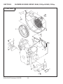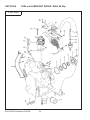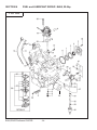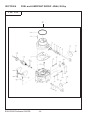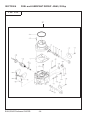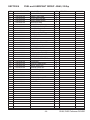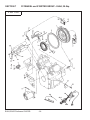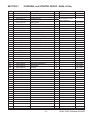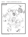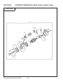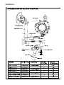
1
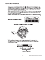
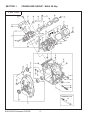
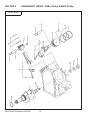
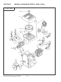
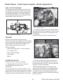
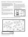
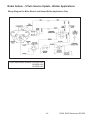
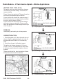
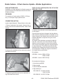
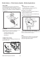
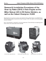
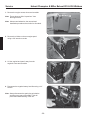
PARTS
MANUAL
Models
EH64, 20.5 hp Engine
EH65, 22.0 hp Engine
Welder Applications
(Onan Performer OHV220)
PUB-EP220W
Rev. 09/05
940 Lively Blvd. • Wood Dale, IL 60191 • Phone: 630-350-8200 • Fax: 630-350-8212
e-mail: [email protected] • www.robinamerica.com
© Copyright 2005 Robin America, Inc.
-3-
EH64, EH65 Performer OHV220
DESCRIPTION
ROBIN
Engine Specification
ONAN
Engine Specification
MILLER HOBART
MILLER BOBCAT
MILLER TRAILBLAZER
LINCOLN ELECTRIC
MILLER BOBCAT
MILLER TRAILBLAZER
MILLER HOBART
EH650DB2322
EH650DB2341
EH650DB2390
EH650DB2332
EH650DC2405
EH650DC2415
EH650DC2420
P220GIOHV-786A
P220GIOHV-2252A
P220GIOHV-2711A
P220GIOHV-1145A
NOTE: Horsepower is as follows;
EH650DB - 20.5hp
EH650DC - 22hp
EH64, EH65 Performer OHV220
-4-
GROUP INDEX
Group Name
Page
CRANKCASE GROUP - EH64 ................................................................... 6
CRANKCASE GROUP - EH65 ................................................................. 10
CRANKSHAFT GROUP ........................................................................... 12
INTAKE and EXHAUST GROUP - EH64.................................................. 14
INTAKE and EXHAUST GROUP - EH65.................................................. 16
GOVERNOR GROUP .............................................................................. 18
BLOWER HOUSING GROUP ................................................................. 20
FUEL, LUBRICANT GROUP - EH64 ........................................................ 22
FUEL, LUBRICANT GROUP - EH65 ........................................................ 24
CARBURETOR - EH64 ............................................................................ 26
CARBURETOR - EH65 ............................................................................ 28
FLYWHEEL and STARTER GROUP - EH64 ............................................ 30
FLYWHEEL and STARTER GROUP - EH65 ............................................ 32
STARTER COMPONENTS ..................................................................... 34
APPENDIX A - Cylinder head & Valve guide change ............................... 36
APPENDIX B - Governor spring and rod positions................................... 37
V-TWIN SERVICE UPDATE WELDER APPLICATIONS ......................... 38
NO START
FUEL CUT-OFF SOLENOID .................................................................... 39
STOP DIODE ........................................................................................... 40
WIRING HARNESS - Welder Applications ............................................... 41
SHUTDOWN RELAY - Welder Applications ............................................. 41
HARD START
IGNITION COIL ........................................................................................ 44
HIGH ALTITUDE KITS.............................................................................. 45
FUEL PUMP ............................................................................................. 46
SPARK PLUG ........................................................................................... 47
REMOVAL & INSTALLATION PROCEDURES
Hobart Champion, Miller Bobcat 225 and 250.......................................... 48
Miller Trailblazer 301G.............................................................................. 66
-5-
EH64, EH65 Performer OHV220
SECTION 1
CRANKCASE GROUP - EH64, 20.5hp
FIG. 100
19
47
46
47
46
48
25
P220GIOHV-2711A
44
EH64, EH65 Performer OHV220
-6-
SECTION 1
REF
1
2
3
4
5
6
7
8
9
10
11
12
13
14
15
16
17
18
19
20
21
22
23
24
25
26
27
28
29
30
31
32
33
34
35
36
37
38
39
40
41
CRANKCASE GROUP - EH64, 20.5hp
ROBIN PART NUMBER DESCRIPTION
263-10102-B1
CRANKCASE CP
263-15802-03
MAIN BEARING
263-15803-03
MAIN BEARING
263-15804-03
MAIN BEARING
X31-00800-80
DOWEL PIN
142-55601-03
PIPE
263-15701-01
PIPE, PULSE
263-15911-A1
BLIND PLUG
044-00800-10
OIL SEAL
263-15901-03
UNION
045-01200-10
STEEL BALL
263-76001-A1
OIL PRESSURE SWITCH
263-11103-D1
MAIN BEARING COVER, AY
263-15802-03
MAIN BEARING
263-15803-03
MAIN BEARING
263-15804-03
MAIN BEARING
044-04200-30
OIL SEAL
263-45001-C1
GOVERNOR GEAR, CP
263-41901-03
GOVERNOR SLEEVE
263-46214-A3
WASHER
263-13001-21
CYLINDER HEAD 1, CP
263-14211-03
VALVE GUIDE
132-07AA0-50
INTAKE VALVE SEAL
010-50802-90
STUD, intake/exhaust
X45-00600-10
STEEL BALL
263-16201-03
PLUG
263-13101-21
CYLINDER HEAD 2, CP
246-15501-01
ROCKER COVER, CP
246-16002-13
ROCKER COVER GASKET
263-15001-13
GASKET 1, CYLINDER HEAD
263-15101-13
GASKET 2, CYLINDER HEAD
263-16001-A3
MAIN BEARING COVER GASKET
263-16006-03
BREATHER PLATE GASKET
263-14301-03
BREATHER COVER
263-14401-01
BREATHER PLATE
263-18001-A3
RUBBER PIPE
263-68511-03
HOSE CLAMP
X31-00600-20
DOWEL PIN
040-11400-30
PLUG
021-11400-20
GASKET
X11-01000-30
FLANGE BOLT
X11-00802-20
FLANGE BOLT
X11-00600-30
FLANGE BOLT
263-46215-A3
THRUST BEARING
263-19001-A3
LIFTING HOOK
-7-
QTY
1
1
1
1
2
2
1
1
1
1
1
1
1
1
1
1
1
1
1
2
1
4
2
8
2
1
1
2
2
1
1
1
2
1
1
1
2
4
1
1
8
10
10
1
2
REMARKS
ONAN PN
187-6000
STD
0.25mm Undersized
0.50mm Undersized
187-6003
187-6006
187-6007
187-6008
187-6170
STD
0.25mm Undersized
0.50mm Undersized
187-6172
187-6011
187-6012
187-6013
187-6014
187-6015
187-6016
187-6017
187-6018
187-6019
187-6020
187-6021
187-6022
187-6023
187-6024
187-6025
187-6026
187-6027
187-6028
187-6029
187-6030
187-6031
187-6032
187-6033
187-6034
187-6035
187-6036
187-6037
EH64, EH65 Performer OHV220
SECTION 1
CRANKCASE GROUP - EH64, 20.5hp
FIG. 100
19
47
46
47
46
48
25
P220GIOHV-2711A
44
EH64, EH65 Performer OHV220
-8-
SECTION 1
REF
43
44
CRANKCASE GROUP - EH64, 20.5hp
ROBIN PART NUMBER DESCRIPTION
263-65005-A3
263-65006-A3
QTY
OIL DRAIN VALVE
ADAPTER
1
1
44
263-68101-B0
OIL DRAIN HOSE AY
1
46
47
48
056-51000-50
263-35341-03
X56-60800-40
CLIP
RETAINER PLATE
CLAMP, choke control
2
2
1
-9-
REMARKS
P220GIOHV-2252A
EH650DB2341
P220GIOHV-786A
EH650DB2322
P220GIOHV-2711A
EH650DB2390
ONAN PN
504-0186
187-6173
187-6173
From S/N 1015769
EH64, EH65 Performer OHV220
SECTION 1
CRANKCASE GROUP - EH65, 22.0hp
FIG. 100
49
47
46
46
47
45
45
45
50
50
42
9
44
43
EH650DC2415
44
EH64, EH65 Performer OHV220
- 10 -
SECTION 1
REF
1
2
3
4
5
6
7
9
10
11
12
13
14
15
16
17
19
20
22
23
24
25
26
27
28
29
30
31
32
33
34
35
36
37
38
39
40
41
42
43
44
44
45
46
47
49
50
CRANKCASE GROUP - EH65, 22.0hp
ROBIN PART NUMBER DESCRIPTION
263-10112-A1
263-15802-03
X31-00800-80
142-55601-03
263-15701-01
263-15911-A1
044-00800-10
263-76001-A1
263-11103-E1
263-15802-03
044-04200-30
263-45001-C1
263-41901-03
263-46215-A3
263-46214-A3
263-13211-A1
010-50802-90
132-07AA0-50
263-13311-A1
263-15502-A3
263-15501-A3
263-16101-A3
263-15021-11
263-15121-01
263-16002-A3
263-16006-03
263-14301-03
280-14401-A1
280-19001-A3
263-18003-03
263-68511-03
X31-00600-20
X40-11400-30
021-11400-20
X11-01000-70
X11-00802-20
X11-00600-30
X11-00601-01
263-15901-03
263-65005-A3
263-65006-A3
263-68101-B1
263-14211-03
056-51000-50
263-35341-03
280-63602-A1
X45-00600-10
QTY
CRANKCASE
MAIN BEARING
DOWEL PIN
PIPE
PIPE, PULSE
BLIND PLUG
OIL SEAL
OIL PRESSURE SWITCH
MAIN BEARING COVER
BALL BEARING
OIL SEAL
GOVERNOR GEAR
GOVERNOR SLEEVE
THRUST BEARING
WASHER
CYLINDER HEAD 1
STUD
SEAL, INTAKE VALVE
CYLINDER HEAD 2
ROCKER COVER w/ oil fill
ROCKER COVER
GASKET, ROCKER COVER
GASKET 1, CYLINDER HEAD
GASKET 2, CYLINDER HEAD
GASKET, MAIN BEARING COVER
GASKET, BREATHER PLATE
BREATHER COVER
BREATHER PLATE
HOOK
RUBBER PIPE
HOSE CLAMP
DOWEL PIN
PLUG
GASKET
FLANGE BOLT
FLANGE BOLT
FLANGE BOLT
FLANGE BOLT
UNION
OIL DRAIN VALVE
ADAPTER
OIL DRAIN HOSE
VALVE GUIDE
CLIP
RETAINER PLATE
OIL FILL CAP
STEEL BALL
- 11 -
1
1
2
2
1
1
1
1
1
1
1
1
1
1
2
1
8
2
1
1
1
2
1
1
1
2
1
1
2
1
2
4
1
2
8
10
2
8
1
1
1
1
4
4
4
1
2
REMARKS
ONAN PN
STD
187-6003
187-6006
187-6170
187-6172
187-6011
187-6012
187-6016
187-6015
187-6024
187-6025
187-6026
187-6028
187-6029
187-6030
187-6031
187-6032
187-6033
187-6034
187-6035
EH650DC2405, DC2420
EH650DC2415
187-6007
504-0186
187-6173
187-6014
EH64, EH65 Performer OHV220
SECTION 2
CRANKSHAFT GROUP - EH64, 20.5hp & EH65, 22.0hp
FIG. 200
EH64, EH65 Performer OHV220
- 12 -
SECTION 2
REF
1
2
2
3
3
4
5
6
7
8
8
8
8
9
10
11
12
CRANKSHAFT GROUP- EH64, 20.5hp & EH65, 22.0hp
ROBIN PART NUMBER
263-21301-21
263-21501-C1
263-22501-00
263-22502-00
263-22601-00
246-23001-13
001-05084-00
263-23411-A3
263-23412-A3
263-23413-A3
263-23301-03
263-23501-07
263-23502-07
263-23503-07
056-52100-20
263-25011-A3
263-25012-A3
263-25013-A3
263-25014-A3
002-18180-00
003-10180-00
003-20180-00
005-32054-01
DESCRIPTION
CRANKSHAFT CP
CRANKSHAFT CP
CONNECTING ROD
CONNECTING ROD
CONNECTING ROD
CONNECTING ROD BOLT
CONNECTING ROD BOLT
PISTON
PISTON
PISTON
PISTON PIN
PISTON RING SET
PISTON RING SET
PISTON RING SET
RETAINING CLIP
SPACER
SPACER
SPACER
SPACER
NUT
WASHER
SPRING WASHER
WOODRUFF KEY
- 13 -
QTY
1
1
2
2
2
4
4
2
2
2
2
2
2
2
4
1
1
1
1
1
1
1
1
REMARKS
ONAN PN
Threaded, Miller - Hobart 187-6039
Taper, Lincoln
STD - EH64
187-6040
Undersized 0.25mm - EH64
STD - EH65 - Miller Hobart
STD- EH64
187-6041
STD- EH65
STD
Oversized 0.25mm
Oversized 0.50mm
187-6043
STD
187-6044
Oversized 0.25mm
Oversized 0.50mm
187-6045
T=0.6
T=0.8
187-6046
T=1.0
187-6047
T=1.2
187-6048
187-6049
EH64
187-6050
EH64
187-6051
187-6052
EH64, EH65 Performer OHV220
SECTION 3
INTAKE and EXHAUST GROUP - EH64, 20.5hp
FIG. 300
19
22
22
EH64, EH65 Performer OHV220
- 14 -
SECTION 3
REF
1
2
4
5
6
7
8
9
10
11
12
13
14
15
16
17
18
19
20
21
22
INTAKE and EXHAUST GROUP - EH64, 20.5hp
ROBIN PART NUMBER
263-33001-03
263-31701-13
263-33301-A3
263-33401-03
263-33502-13
246-33611-03
246-35501-03
246-33711-13
239-35001-03
263-35311-01
246-36101-10
014-90800-21
017-00800-90
263-35503-A3
002-38080-00
263-32610-A1
263-32620-01
263-32630-03
263-32640-01
X10-10500-10
263-35201-A1
DESCRIPTION
INTAKE MANIFOLD
CAMSHAFT
TAPPET
INTAKE VALVE
EXHAUST VALVE
VALVE SPRING
VALVE COLLET
SPRING RETAINER
ROCKER SHAFT
PUSH ROD
ROCKER ARM AY
ADJUSTING SCREW
NUT
MANIFOLD GASKET
FLANGE NUT
CLEANER ELEMENT
CLEANER BASE
CLEANER COVER
WING NUT
BOLT
GASKET, EXHAUST
- 15 -
QTY
1
1
4
2
2
4
8
4
2
4
4
4
4
2
4
1
1
1
1
3
2
REMARKS
ONAN PN
187-6053
187-6055
187-6057
2 Per Valve
187-6059
187-6060
187-6061
135.5mm
187-6063
187-6064
187-6065
187-6066
187-6067
187-6068
187-6069
187-6070
187-6071
EH64, EH65 Performer OHV220
SECTION 3
INTAKE and EXHAUST GROUP - EH65, 22.0hp
FIG. 300
24
EH64, EH65 Performer OHV220
- 16 -
SECTION 3
REF
1
2
3
4
5
6
7
8
9
10
11
12
13
14
15
16
17
18
19
20
21
22
23
24
INTAKE and EXHAUST GROUP - EH65, 22.0hp
ROBIN PART NUMBER DESCRIPTION
280-33001-C3
INTAKE MANIFOLD
280-31701-13
CAMSHAFT
263-33301-A3
TAPPET
263-33401-03
INTAKE VALVE
263-33502-13
EXHAUST VALVE
246-33611-03
VALVE SPRING
246-35501-03
COLLET VALVE
246-33711-13
SPRING RETAINER
263-35321-B1
PUSH ROD
267-36101-13
ROCKER ARM
261-35801-13
BOLT, PIVOT
267-35701-03
PIVOT
017-00601-10
NUT
263-37001-A3
GUIDE PLATE
263-35503-A3
GASKET, INTAKE MANIFOLD
280-32601-A0
AIR CLEANER AY
263-32610-A1
CLEANER ELEMENT
280-32620-A1
CLEANER BASE
263-32630-03
CLEANER COVER
263-32640-01
WING NUT
263-95111-A3
LABEL, ONAN BY ROBIN
002-38080-00
FLANGE NUT
X11-00600-20
FLANGE BOLT
270-35201-01
GASKET
- 17 -
QTY
1
1
4
2
2
4
8
4
4
4
4
4
4
2
2
1
1
1
1
1
1
4
3
2
REMARKS
ONAN PN
187-6055
187-6057
2 per valve
187-6059
187-6060
138.5mm
187-6066
187-6068
187-6070
187-6071
187-6067
EH64, EH65 Performer OHV220
SECTION 4
GOVERNOR GROUP- EH64, 20.5hp & EH65, 22.0hp
FIG. 400
22
14
17
22
7
EH64, EH65 Performer OHV220
- 18 -
SECTION 4
REF
1
2
3
4
6
6
7
8
GOVERNOR GROUP- EH64, 20.5hp & EH65, 22.0hp
ROBIN PART NUMBER DESCRIPTION
263-46021-B3
CHOKE LEVER
263-46011-A3
CHOKE CONTROL ROD
261-45201-03
RETURN SPRING
226-43101-01
LINK PIVOT
263-42301-B3
GOVERNOR LEVER
263-46021-B3
CHOKE LEVER
263-42201-A3
GOVERNOR SHAFT
263-42507-03
GOVERNOR SPRING, black
QTY
1
1
1
1
1
1
1
1
8
263-42509-A3
GOVERNOR SPRING, blue
1
9
10
11
12
13
14
15
16
17
18
19
20
21
22
23
263-42509-A3
263-42701-A3
263-42801-03
263-43311-A3
263-45021-A2
261-43901-03
005-11060-01
001-14063-00
X18-60600-20
X11-00600-20
X11-50500-20
002-27050-00
002-38060-00
001-17052-00
003-10080-00
X23-00801-50
GOVERNOR SPRING, blue
GOVERNOR ROD
ROD SPRING
SPEED CONTROL LEVER
SPEED CONTROL BRACKET
CLAMP
SNAP PIN
BOLT and WASHER AY
NUT
FLANGE BOLT
BOLT and WASHER AY
NUT
FLANGE NUT
BOLT and WASHER AY
WASHER
SPACER
1
1
1
1
1
1
1
1
1
2
1
1
1
1
2
1
- 19 -
REMARKS
ONAN PN
187-6075
187-6076
187-6077
187-6175
EH650DC2420
187-6079
P220GIOHV-786A
EH650DB2322
P220GIOHV-1145A
EH650DB2332
P220GIOHV-2252A
EH650DB2341
P220GIOHV-2711A
EH650DB2390
EH65
187-6081
187-6082
187-6083
187-6084
187-6085
187-6086
187-6087
187-6088
187-6089
187-6090
187-6091
187-6092
187-6093
EH64, EH65 Performer OHV220
SECTION 5
BLOWER HOUSING GROUP- EH64, 20.5hp & EH65, 22.0hp
FIG. 500
7
13
13
13
4
6
6
6
14
5
14
12
6
EH64, EH65 Performer OHV220
- 20 -
SECTION 5
REF
1
2
3
4
5
6
7
8
9
11
12
13
14
BLOWER HOUSING GROUP- EH64, 20.5hp & EH65, 22.0hp
ROBIN PART NUMBER
263-51101-B2
263-51121-B2
263-52603-A1
263-52612-A1
263-52703-B1
263-52704-A1
263-52801-03
263-52911-B2
263-52912-A2
X11-00600-20
X11-00601-40
001-14061-60
263-92001-03
263-54101-02
263-95112-A3
X11-00600-30
X11-00600-10
DESCRIPTION
BLOWER HOUSING
BLOWER HOUSING
CYLINDER BAFFLE 1
CYLINDER BAFFLE 1
CYLINDER BAFFLE 2
CYLINDER BAFFLE 2
CYLINDER BAFFLE 3
CYLINDER BAFFLE 4, UNIT
CYLINDER BAFFLE 4
FLANGE BOLT
FLANGE BOLT
BOLT and WASHER AY
LABEL, warning
COOLING BLOWER UNIT
LABEL, trademark
FLANGE BOLT
FLANGE BOLT
- 21 -
QTY
1
1
1
1
1
1
1
1
1
5
2
4
1
1
1
4
2
REMARKS
EH64
EH65
EH64
EH65
EH64
EH65
ONAN PN
187-6094
187-6097
EH64
EH65
EH64
EH64
187-6099
187-6100
187-6102
187-6073
EH64, EH65 Performer OHV220
SECTION 6
FUEL and LUBRICANT GROUP- EH64, 20.5hp
FIG. 600
38
15
32
36
31
12
30
22
EH64, EH65 Performer OHV220
- 22 -
SECTION 6
REF
1
2
3
4
5
6
7
8
9
10
11
12
13
14
15
16
17
18
19
20
21
22
23
24
25
27
29
30
31
32
33
34
35
36
37
38
FUEL and LUBRICANT GROUP - EH64, 20.5hp
ROBIN PART NUMBER DESCRIPTION
263-63901-03
INNER ROTOR
263-63902-03
OUTER ROTOR
263-64302-02
OIL PUMP FILTER UNIT
263-64001-B1
OIL PUMP COVER, CP
044-03501-70
OIL SEAL
X24-89000-30
O RING
263-65001-13
OIL RELIEF PLUG
003-70140-00
ALUMINUM GASKET
248-65601-03
RELIEF VALVE SPRING
006-90308-00
STEEL BALL
248-65801-00
OIL FILTER AY
263-63604-11
OIL GAUGE CP
246-63606-09
OIL FILL CAP
021-31800-10
GASKET
263-68006-B3
RUBBER PIPE
263-68501-03
HOSE CLAMP
263-62431-00
CARBURETOR
263-66201-A3
CARBURETOR GASKET
280-62201-00
FUEL PUMP
263-65003-A1
FUEL PUMP BRACKET
263-68009-B3
RUBBER PIPE
024-01000-10
OIL GAUGE O RING
263-65011-A3
BOLT
X11-00801-10
FLANGE BOLT
X11-00601-40
FLANGE BOLT
263-65012-A3
FUEL FILTER
263-65102-A3
OIL FILL TUBE
085-10301-10
RUBBER PIPE
206-75501-01
CLAMP CP
263-63621-01
OIL GAUGE TUBE
021-81800-10
OIL FILL TUBE GASKET
056-60001-70
STRAP CLAMP
002-18180-00
HEX NUT
X11-00600-20
FLANGE BOLT
X11-00600-90
FLANGE BOLT
263-67102-A3
SPACER
- 23 -
QTY
1
1
1
1
1
1
1
1
1
1
1
1
1
1
2
6
1
1
1
1
1
2
1
2
4
1
1
1
2
1
1
2
1
5
2
2
REMARKS
ONAN PN
187-6103
187-6104
187-6108
187-6109
187-6110
187-6111
187-6112
187-6191
187-6192
187-6113
187-6114
NEW - High performance 187-6115
187-6116
187-6196
187-6194
187-6117
187-6118
187-6119
187-6199
187-6121
187-6198
187-6200
187-6201
187-6218
815-0753
EH64, EH65 Performer OHV220
SECTION 6
FUEL and LUBRICANT GROUP- EH65, 22.0hp
FIG. 600
38
EH64, EH65 Performer OHV220
- 24 -
SECTION 6
REF
1
2
3
4
5
6
7
8
9
10
12
13
14
15
16
17
18
19
20
21
22
23
24
25
26
27
28
29
30
32
33
34
35
36
37
38
FUEL and LUBRICANT GROUP - EH65, 22.0hp
ROBIN PART NUMBER DESCRIPTION
263-63901-03
INNER ROTOR
263-63902-03
OUTER ROTOR
263-64302-02
OIL PUMP FILTER UNIT
263-64001-B1
OIL PUMP COVER
044-03501-70
OIL SEAL
X24-89003-30
O RING
263-65001-13
OIL RELIEF PLUG
003-70140-00
ALUMINUM GASKET
248-65601-03
RELIEF VALVE SPRING
006-90308-00
STEEL BALL
263-63604-11
OIL GAUGE CP
280-63602-A1
OIL FILL CAP
263-63622-01
GAUGE
024-01000-10
O RING
263-62606-B1
FUEL PIPE
263-68006-B3
RUBBER PIPE
263-68501-03
HOSE CLAMP
263-62391-00
CARBURETOR
085-10301-10
RUBBER PIPE
206-75501-01
CLAMP
263-66201-A3
GASKET, CARBURETOR
280-62201-00
FUEL PUMP
251-62251-08
DIAPHRAGM GASKET SET
251-62250-08
SCREW
263-65002-A3
BRACKET, FUEL PUMP
263-62653-B1
PULSE PIPE
263-68008-B3
RUBBER PIPE
263-68501-03
HOSE CLAMP
263-65012-A3
FUEL FILTER
263-68007-B3
RUBBER PIPE
263-68501-03
HOSE CLAMP
263-65011-A3
FLANGE BOLT
X11-00801-10
FLANGE BOLT
X11-00600-30
FLANGE BOLT
X11-00600-20
FLANGE BOLT
248-65801-00
OIL FILTER AY
- 25 -
QTY
1
1
1
1
1
1
1
1
1
1
1
1
2
1
1
2
1
1
2
1
1
1
4
1
1
1
2
1
1
2
1
2
4
5
1
REMARKS
ONAN PN
187-6103
187-6104
187-6108
187-6109
187-6110
187-6111
187-6112
187-6191
187-6194
187-6113
187-6121
187-6114
NEW- High Performance 187-6115
187-6119
187-6117
815-0753
EH64, EH65 Performer OHV220
SECTION 6
FUEL and LUBRICANT GROUP - EH64, 20.5hp
FIG. 610
17
EH64, EH65 Performer OHV220
- 26 -
SECTION 6
REF
17
-1
-4
-5
-6
-7
-8
-9
-10
-11
-12
-13
-14
-15
-16
-17
-18
-19
-20
-21
-22
-23
-24
-25
-26
-27
-28
-29
-30
-31
-32
-33
-34
-35
-36
FUEL and LUBRICANT GROUP - EH64, 20.5hp
ROBIN PART NUMBER DESCRIPTION
263-62431-00
CARBURETOR AY
280-62545-08
GASKET,AIR HORN
263-62524-08
LEVER ASSY,CHOKE
258-62551-08
RING,CHOKE LEVER
263-62445-08
SPRING,CHOKE
280-62550-08
COLLAR,CHOKE
258-62554-08
FILTER,CHOKE SHAFT
263-62520-08
SHAFT ASSY,CHOKE
258-62525-08
VALVE,CHOKE
258-62555-08
SCREW,VALVE SET
258-62450-08
SCREW,AIR HORN SET
226-62501-08
VALVE,FLOAT
280-62505-08
FLOAT
258-62515-08
PIN,FLOAT
258-62556-08
SCREW,FLOAT PIN SET
263-62400-08
JET,MAIN
258-62557-18
SOLENOID VALVE ASSY
258-62546-08
GASKET,SOLENOID
258-62420-08
JET,SLOW
258-62445-08
SPRING,ADJUST SCREW
263-62451-08
SCREW,THRO.ADJUST
261-62435-08
NEEDLE, idle adjust
263-62531-08
SHAFT ASSY,THROTTLE
226-62580-08
FILTER,AIR
258-62570-08
COLLAR,THRO.SHAFT
263-62535-08
VALVE,THROTTLE
261-62352-08
SCREW,VALVE SET
258-62560-08
PLUG,EXPANSION
258-62566-08
CLAMP,SOLENOID
263-62552-08
PLUG
215-62353-08
SCREW,DRAIN
215-62446-08
SPRING,DRAIN SCREW
263-62560-08
“O”RING,AIR HORN
263-62555-08
GASKET
261-62358-08
PLUG, anti tamper
- 27 -
QTY
1
1
1
1
1
1
1
1
1
2
4
1
1
1
1
1
1
1
1
1
1
1
1
1
1
1
2
1
1
1
1
1
1
1
1
REMARKS
ONAN PN
EH64, EH65 Performer OHV220
SECTION 6
FUEL and LUBRICANT GROUP - EH65, 22.0hp
FIG. 610
17
EH64, EH65 Performer OHV220
- 28 -
SECTION 6
REF
17
-1
-4
-5
-6
-7
-8
-9
-10
-11
-12
-13
-14
-15
-16
-17
-18
-19
-20
-21
-22
-23
-24
-25
-26
-27
-28
-29
-30
-31
-32
-33
-34
-35
-36
FUEL and LUBRICANT GROUP - EH65, 22.0hp
ROBIN PART NUMBER DESCRIPTION
263-62391-00
CARBURETOR AY
280-62545-08
GASKET,AIR HORN
263-62524-08
LEVER ASSY,CHOKE
258-62551-08
RING,CHOKE LEVER
263-62445-08
SPRING,CHOKE
280-62550-08
COLLAR,CHOKE
258-62554-08
FILTER,CHOKE SHAFT
263-62520-08
SHAFT ASSY,CHOKE
258-62525-08
VALVE,CHOKE
258-62555-08
SCREW,VALVE SET
258-62450-08
SCREW,AIR HORN SET
226-62501-08
VALVE,FLOAT
280-62505-08
FLOAT
258-62515-08
PIN,FLOAT
258-62556-08
SCREW,FLOAT PIN SET
263-62400-08
JET,MAIN
263-62556-08
SOLENOID VALVE ASSY
258-62546-08
GASKET,SOLENOID
258-62420-08
JET,SLOW
258-62445-08
SPRING,ADJUST SCREW
263-62451-08
SCREW,THRO.ADJUST
261-62435-08
NEEDLE, idle adjust
263-62531-08
SHAFT ASSY,THROTTLE
226-62580-08
FILTER,AIR
258-62570-08
COLLAR,THRO.SHAFT
263-62535-08
VALVE,THROTTLE
261-62352-08
SCREW,VALVE SET
258-62560-08
PLUG,EXPANSION
258-62566-08
CLAMP,SOLENOID
263-62552-08
PLUG
215-62353-08
SCREW,DRAIN
215-62446-08
SPRING,DRAIN SCREW
263-62560-08
“O”RING,AIR HORN
263-62555-08
GASKET
261-62358-08
PLUG, anti tamper
- 29 -
QTY
1
1
1
1
1
1
1
1
1
2
4
1
1
1
1
1
1
1
1
1
1
1
1
1
1
1
2
1
1
1
1
1
1
1
1
REMARKS
ONAN PN
EH64, EH65 Performer OHV220
SECTION 7
FLYWHEEL and STARTER GROUP - EH64, 20.5hp
FIG. 700
33
32
26
28
26
20
22
20-1
20-2
EH64, EH65 Performer OHV220
- 30 -
SECTION 7
REF
1
2
3
FLYWHEEL and STARTER GROUP - EH64, 20.5hp
ROBIN PART NUMBER DESCRIPTION
263-77202-11
FLYWHEEL CP
263-78202-11
IGNITION COIL CP
263-79411-A1
CHARGE COIL
QTY
1
2
1
5
6
7
8
9
10
11
12
13
14
15
16
17
18
20
20-1
20-2
21
22
23
24
25
26
28
263-71001-03
263-70502-A0
263-71901-01
KU3-11052-21
X65-01407-30
X65-51000-10
X65-91000-10
001-14062-50
X13-10500-40
X11-00801-00
X11-00600-10
X56-30000-80
X11-00601-40
206-75501-01
263-73116-A1
WELDER FUSE
EH65A0256
263-72003-A1
263-73117-A1
010-00500-60
263-75403-B1
263-75302-A1
263-79902-A3
056-61500-20
RING GEAR
STARTING MOTOR
REGULATOR
STOP DIODE
SPARK PLUG
SPARK PLUG CAP
PLUG TERMINAL
BOLT and WASHER
SCREW and WASHER
FLANGE BOLT
FLANGE BOLT
WIRE BAND
FLANGE BOLT
CLAMP
HARNESS, ENGINE TO WELDER
FUSE
DIODE AY
SHUTDOWN RELAY
HARNESS, RELAY TO ENGINE
RELAY BOLT
SOLENOID BRACKET
SOLENOID
SCREW
CLAMP, HARNESS
1
1
1
1
2
2
2
4
4
2
1
3
2
2
1
1
1
1
1
1
1
1
2
1
30
31
32
33
002-38080-00
X11-00600-10
001-13082-00
X31-80300-20
NUT
FLANGE BOLT
BOLT and WASHER
ROLL PIN
1
2
1
1
- 31 -
REMARKS
ONAN PN
P220GIOHV-1145A
EH650DB2332
187-6159
187-6184
187-6160
NGK BPR4EY
187-6163
187-6166
187-6167
Incl 20-1, 20-2
BUSS AGX 30amp
187-6118
187-6169
187-6187
187-6188
187-6189
187-6180
187-6181
187-6182
P220GIOHV-2252A
EH650DB2341
EH64, EH65 Performer OHV220
SECTION 7
FLYWHEEL and STARTER GROUP - EH65, 22.0hp
FIG. 700
33
26
32
26
20
20-1
20-2
EH64, EH65 Performer OHV220
- 32 -
SECTION 7
REF
1
2
3
5
6
7
8
9
10
11
12
13
14
15
16
17
18
20
20-1
20-2
24
25
26
30
32
33
FLYWHEEL and STARTER GROUP - EH65, 22.0hp
ROBIN PART NUMBER
263-77202-01
263-78202-11
263-79411-A1
263-71001-03
263-70502-A0
263-71901-01
KU3-11052-21
X65-01407-30
X65-51000-10
X65-91000-10
001-14062-50
X13-10500-40
X11-00801-00
X11-00600-10
X56-30000-80
X11-00601-40
206-75501-01
263-73118-A1
EH65A0256
263-75404-A1
263-75302-A1
263-79902-A3
002-38080-00
001-13082-00
X31-80300-20
DESCRIPTION
FLYWHEEL CP
IGNITION COIL CP
CHARGE COIL
QTY
1
2
1
RING GEAR
STARTING MOTOR
REGULATOR
STOP DIODE
SPARK PLUG
SPARK PLUG CAP
PLUG TERMINAL
BOLT and WASHER
SCREW and WASHER
FLANGE BOLT
FLANGE BOLT
WIRE BAND
FLANGE BOLT
CLAMP
HARNESS, ENGINE TO WELDER
FUSE
DIODE AY
SOLENOID BRACKET
SOLENOID
SCREW
NUT
BOLT and WASHER
ROLL PIN
- 33 -
1
1
1
1
2
2
2
4
4
2
1
4
2
1
1
1
1
1
1
2
1
1
1
REMARKS
ONAN PN
P220GIOHV-1145A
EH650DB2332
187-6159
187-6184
187-6160
NGK BPR4EY
187-6163
187-6166
187-6167
Incl 20-1, 20-2
BUSS AGX 30amp
187-6118
187-6169
187-6187
187-6181
187-6182
EH64, EH65 Performer OHV220
SECTION 8
STARTER COMPONENTS- EH64, 20.5hp & EH65, 22.0hp
FIG. 800
EH64, EH65 Performer OHV220
- 34 -
SECTION 8
REF
1
2
3
4
5
6
7
8
STARTER COMPONENTS- EH64, 20.5hp & EH65, 22.0hp
ROBIN PART NUMBER DESCRIPTION
263-70502-A0
STARTING MOTOR AY
263-70550-08
THRUST WASHER KIT
210-70534-08
PINION STOPPER SET
263-70505-08
REAR COVER
255-70531-08
BRUSH HOLDER
255-70521-08
PINION STOPPER SET
243-70525-08
SHIFT LEVER KIT
263-70515-08
MAGNETIC SWITCH
- 35 -
QTY
1
1
1
1
1
1
1
1
REMARKS
ONAN PN
187-6184
187-6208
187-6202
187-6203
187-6204
187-6205
187-6206
187-6207
EH64, EH65 Performer OHV220
APPENDIX A
EH64, EH65 Performer OHV220
- 36 -
APPENDIX B
- 37 -
EH64, EH65 Performer OHV220
Robin Subaru - V-Twin Service Update - Welder Applications
Forward
The following three conditions must be fulfilled for satisfactory engine start
1. The cylinder filled with a proper fuel-air mixture.
2. Good compression in the cylinder.
3. Good spark, properly timed, to ignite the mixture.
The engine cannot be started unless these three conditions are met.
There are also other factors which make engine start difficult, e.g., a heavy load on the engine
when it is about to start at low speed, and a high back pressure due to a long exhaust pipe.
The most common causes of engine troubles and solutions are given throughout the following
pages.
EH64, EH65 Performer OHV220
- 38 -
Robin Subaru - V-Twin Service Update - Welder Applications
FUEL CUT-OFF SOLENOID
The fuel solenoid controls the flow of fuel from the
float chamber into the main jet. When the engine is
not running, the plunger will remain extended. During starting and operation, 12 volts DC is applied
to the solenoid and the plunger is retracted. Fuel is
then allowed to flow to the main jet.
Fig. 2 - Tap the solenoid
2. Loosen the solenoid a few turns without removing the solenoid from the carburetor. This will extract
the plunger from the main jet. Re-tighten the solenoid and test.
Fig. 1 - Carburetor cross section
If solenoid does not function, proceed to step 3.
PROBLEM
No Start. Engine cranks but does not start.
Stale fuel can cause gum deposits around the plunger in the solenoid not allowing the plunger to retract
during starting. This stops the fuel supply to the
main jet causing the engine not to start.
Verify the following:
• Spark at the spark plug - if dry see remedies
• Oil - Check oil level
• Fuel - Check fuel supply
• Crank Speed
• Battery
Fig. 3 - Clean the solenoid plunger
CORRECTIVE ACTION
Please follow in this order as necessary.
1. Tapping lightly on the side of the solenoid.
This may free the plunger from any
gum build up.
3. Remove solenoid from carburetor. Spray carburetor cleaner into the plunger end, as well as in
the carburetor body. See Fig. 4. Gently manipulate
plunger to loosen gum deposits.
Test the solenoid operation by turning the start
switch to the “Start” position. The solenoid plunger
Turn the start switch to the “Start” position to energize the solenoid. The solenoid will make a “clicking” will retract when 12V DC power is applied. Note:
solenoid will need to be grounded when power is
sound as the 12V DC power is applied. If no sound
is heard, proceed to step number two. See figure 2. applied. If solenoid does not function after cleaning,
proceed to step 4.
- 39 -
EH64, EH65 Performer OHV220
Robin Subaru - V-Twin Service Update - Welder Applications
! WARNING !
STOP DIODE
Remove solenoid only on cold engine.
When solenoid is removed from carburetor,
any fuel in the float chamber will drain out.
The stop diode serves to isolate each ignition coil
while allowing one grounding lead to be used to
ground both coils to stop the engine. It is located
under the shroud, above the starter motor.
Fig. 4 - Stop diode mounted on engine
PROBLEM
Fig. 4 - Clean the carburetor solenoid hole and main jet
Engine cranks but does not start. The condition
could be caused by a defective stop diode.
4. If cleaning does not restore the solenoid operation, replace fuel solenoid (part no. 263-62556-08).
To replace the solenoid, cut red wire close to the
solenoid. Install the new solenoid and reconnect the
wires using a crimp connector.
CORRECTIVE ACTION
• Measure the continuity between the wires.
Black (-) needle
A
B
B
8
C
Continuity
C
Continuity
8
(Continuity = Closed Circuit /
8 8
8
A
Red (+)
needle
C
= Open Circuit)
B
A
Fig. 5 - Cut the wire close to the solenoid when replacing
• Replace the stop diode if the actual value
differs from the rated value.
EH64, EH65 Performer OHV220
- 40 -
Robin Subaru - V-Twin Service Update - Welder Applications
WIRING HARNESS
SHUTDOWN RELAY
For Miller Electric and Hobart Welder Applications Only
For Miller Electric and Hobart Welder Applications Only - EH64, 20.5hp
The wiring harness on the Onan/Robin OHV engines
for Miller Electric and Hobart, includes a diode and
a Buss AGX 30 amp fuse. The purpose of the fuse
is to protect the wiring harness should a short occur.
Note: it is important that the correct fuse length (15/
16 in.) be installed in the fuse holder.
The relay contacts are wired between the Stop
Diode and Ground. The relay contacts are normally
closed and ground the ignition coils (stop the engine). Please refer to the relay diagram and the
wiring diagram.
The purpose of the bypass diode is to prevent feedback to the starter solenoid. If the diode is “shorted”,
the engine continues to crank after the start stop
switch is released from the start position. If the diode
is “open” the engine will crank, but will not start.
An open diode will not allow the shutdown relay to
energize and remove the ground from the ignition
coils. The harness is located on the oil filter side of
the engine.
PROBLEM
Engine will not crank or start.
Could be caused by either a blown fuse or faulty
diode.
The relay has two functions. During engine running
the relay coil is energized by a 12V DC power signal
controlled by the oil pressure switch. This removes
the ignition ground and allows the engine to operate.
If the oil pressure drops below the minimum pressure, the oil pressure switch will switch the power off
the relay coil and the ignition coils will be grounded
to turn off the engine.
The relay also has an important function during engine startup. At startup, the oil pressure will initially
be low. During start-up the welder control system
will provide 12V DC to the relay coil to remove the
ignition coil ground and to by-pass the oil pressure
switch. This allows the engine to start quickly.
CORRECTIVE ACTION
• Split the harness open with your hands to
reveal the diode and the fuse.
Replace the diode, part # EH65A0256.
PROBLEM
1. The engine will crank, but will not start.
2. The engine does not shut down immediately when
the engine is turned off.
SYMPTOMS
1. Fuel to the spark plugs (plug wet) - OK
2. No spark
3. The Stop Diode tests good
- 41 -
EH64, EH65 Performer OHV220
Robin Subaru - V-Twin Service Update - Welder Applications
Note: If the engine wiring harness is disconnected from the welder, the engine will not start.
Among other functions, the welder control system provides power to the relay during start-up
to remove the ignition coil ground.
TEST PROCEDURES
Step 1
Remove the relay and unplug the wire connector.
Check for continuity across the normally closed contacts, spade connectors #30 and #87A. If there is no
continuity, the relay should be replaced.
Step 3
Apply 9 - 12V DC across the relay coil on spade
connectors #85 and #86 (brass colored). Check
for continuity across the normally closed contacts,
spade connectors #30 and #87A. With the relay coil
energized, there should be no continuity (open circuit). If there is continuity while the coil is powered,
the relay should be replaced.
Relay Diagram and Schematic
Step 2
Apply 9 - 12V DC across the relay coil on spade
connectors #85 and #86 (brass colored). A “clicking”
sound should be heard as the power is applied and
removed. Proceed to step 3.
Wiring Diagram For Miller Electric and Hobart Welder Applications Only
Engine Specification Numbers: EH650DB2332
EH650DB2341
EH650DB2390
EH64, EH65 Performer OHV220
- 42 -
Robin Subaru - V-Twin Service Update - Welder Applications
Wiring Diagram For Miller Electric and Hobart Welder Applications Only
Engine Specification Numbers: EH650DC2405
EH650DC2415
EH650DC2420
- 43 -
EH64, EH65 Performer OHV220
Robin Subaru - V-Twin Service Update - Welder Applications
IGNITION COILS - EH64, 20.5hp
The ignition coils have gone through two changes.
The first being a vendor change. The second, to
improve starting.
Figure 1 shows the original coil. These coils perform
well and only be replaced upon coil failure.
Figure 2 shows the coil after the vendor change. If
this coil is being used, we suggest that you update
the coil to the one shown in figure 3.
Figure 3 shows the newest coil. This last change
was made to improve startability. Please note the
White dot identifies the current design from the previous coil (fig. 2).
Bolt P/N 001-14063-00
Fig 1 - Original Ignition Coil - Do Not Replace
PROBLEM
Hard starting, hard starting in cold temperature.
CORRECTIVE ACTION
1. Check the ignition coil. If the coils match the coil
shown in figure 2, replace both coils and order (2)
plug terminals #X65-91000-10. File a warranty
claim.
2. Check the coil gap to the flywheel magnet.
The ignition coil air gap clearance is 0.3 mm or
(0.012 - 0.015 in). This measurement is done with
a thickness gauge between the ignition coils and
flywheel.
Tighten the left bolt first, then the right bolt. Rotate
the flywheel and recheck the clearance.
Bolt P/N 001-14062-50
Fig 2 - New Design - After Vendor Change
Bolt P/N 001-14062-50
Air Gap: 0.03mm (.012 -.015 in) Torque: 5.1 - 6.5 ft-lb.
EH64, EH65 Performer OHV220
Fig 3 - Revised New Design - White Paint Mark
- 44 -
Robin Subaru - V-Twin Service Update - Welder Applications
NOTE: DO NOT OVERTIGHTEN THE JET OR THE
Installation of a high altitude kit will help increase en- HEAD WILL STRIP
gine performance and decrease exhaust emissions
at higher altitudes.
HIGH ALTITUDE KITS
PROBLEM
For operation of engine above 5,000 ft (1,500 meters), to avoid poor engine performance.
CORRECTIVE ACTION
Install a High Altitude kit. Please follow in this order.
1. Remove carburetor from engine. Unscrew the solenoid valve from the carburetor with a 19mm metric
wrench.
4. Replace solenoid valve, and reinstall carburetor
on the engine.
Once the jets have been changed, the high altitude
label should be affixed somewhere noticeable on the
engine (shroud or air cleaner cover) and the owner’s
manual addendum is required to be given to the
engine owner.
2. Unscrew the standard jet from carburetor using a
flat head screw driver.
An engine which has been converted for high altitude use, cannot be run at lower altitudes. A high
altitude converted engine running at lower altitude
will run lean causing the engine to overheat leading
to internal damage. The affixed high altitude label
identifies which engines have been converted, and
should be taken off when the engine is restored to
its original factory specification.
Kit numbers:
92630024 - Used on EH64, 20.5hp
EH65, 22.0hp
92630025 - Used on EH72 25.0hp
Kits include the following:
1. Instructions and BOM
2. Warning label
3. Owner’s Manual addendum
4. High altitude jet:
263-62463-08 - for EH64, 20.5hp
3. Install the high altitude jet into the carburetor using a flat head screw driver.
EH65, 22.0hp
263-62640-08 - for EH72 25.0hp
- 45 -
EH64, EH65 Performer OHV220
Robin Subaru - V-Twin Service Update - Welder Applications
Note:
FUEL PUMP
A diaphragm type fuel pump is located either in
front of the engine below the aircleaner or on the oil
filter side of the engine. The pump utilizes pressure
changes in the crankcase to actuate a diaphragm to
pump the fuel.
Oil capacity: 53 oz. (1.55 Liters)
Use SAE #20, #30 or 10W-30 class SE or
higher automobile engine oil.
Be certain it is not overfilled.
2. Check hose and hose connections for leaks. If
cracked or damaged, replace.
3. Replace fuel pump using the new high lift pump.
Part number: 280-62201-00
Blue dot
PROBLEM
Hard starting. Can not get fuel to carburetor. This
condition could be cause by the following:
• Overfilling crankcase with oil
Fig 1 - Revised New Design - Blue Paint Mark
The new High Lift fuel pump can be identified by the
Blue dot, as shown below in figure 1.
• High Ambient Temperatures
• High Altitude
Note:
CORRECTIVE ACTION
1. Check the oil level. Overfilling will block the fuel
pump breather port.
EH64, EH65 Performer OHV220
- 46 -
If operating above 5,000 feet, you may need to
change the main jets when replacing the fuel
pump. See High altitude section.
Robin Subaru - V-Twin Service Update - Welder Applications
SPARK PLUG
PROBLEM
Hard starting when the engine is cold. The engine
will run on one cylinder but is hard starting.
CORRECTIVE ACTION
Check for a fouled spark plug. The correct spark
plug is NGK BPR4EY, Pro V. This plug has a split
center electrode, called the V-Groove.
ENGINE OPERATION WHILE DISCONECTED
FROM WELDER CONTROL BOARD
For Miller Electric and Hobart Welder Applications Only
Should you need to “hot-wire” the engine for testing
purposes on the Miller Welder, the following wires
need to be connected after the plug has been disconnected from the welder portion. This procedure
may be required to test the engine separate from the
welder start -stop circuit.
This forces the spark to the outer edge of the ground
electrode, placing it closer to the air/fuel mixture.
Note: plug is located behind side panel on the center
This allows the spark to more quickly ignite the mix- support bracket.
ture, providing more complete combustion.
Run Condition-Connect Red and Blue Wire
The gap is set at 0.025 inches or .6 to .7mm.
(places power to the bypass relay and ungrounds
the magneto and puts power to the fuel solenoid).
The EH65, 20.0hp, does not use the bypass relay.
However, wiring connection will be the same.
Crank Condition-Connect Yellow and Red Wire
(cranks engine)
After engine starts, disconnect the Yellow and Red
crank wire circuit.
Note: See the wiring diagram in the “Shutdown
Relay” section.
Part Number: X65-01407-30
- 47 -
EH64, EH65 Performer OHV220
Service
Hobart Champion & Miller Bobcat 225 & 250 Welders
- 48 -
Service
Hobart Champion & Miller Bobcat 225 & 250 Welders
Removal & Installation Procedures of the
Onan by Robin (OHV) V-Twin Engine on the
Miller Bobcat 225 & 250 Series Welders, as
well as the Hobart Champion 10,000
Should it become necessary to remove and install the Onan by Robin Engine in the Miller Bobcat
225 & 250 series welder, as well as the Hobart Champion 10000, the steps on the following pages
should be followed.
Note: This information is intended for a service professional. Follow all safety and operating procedures shown in the owners and service manuals.
Onan by Robin 22hp (side view)
Onan by Robin 22hp (back view)
- 49 -
Onan by Robin 20.5 hp (side view)
Service
Hobart Champion & Miller Bobcat 225 & 250 Welders
1. Remove the engine access doors and set aside.
Note: These doors are lifted “up and out” from
the engine frame.
Note: Unless noted otherwise, the removal and
installation procedures are similar for all models .
2. Remove the 8 bolts on the rear engine panel
using a 3/8” wrench or socket.
3. Lift the ‘engine back panel’ away from the
engine & frame and set aside.
4. Disconnect the negative battery lead first using a 1/2”
wrench.
Note: Always disconnect the spark plug wire before
working on any part of the welder. This will
prevent accidental starting of the unit.
- 50 -
Service
Hobart Champion & Miller Bobcat 225 & 250 Welders
5. After disconnecting the battery positive terminal with
the 1/2” wrench, remove the battery hold down bracket
using a 7/16” wrench. Then remove the battery from
the unit and set aside.
6. Remove the gas cap, exhaust pipe, and the 8 bolts
that hold down the units top cover. Lift the cover
off and set aside.
7.
Remove the 2 bolts from each side panel. Lift the side
panels out and set aside.
Note:
After removing the bolts, be careful to lift the side
panels ‘up’ and ‘out’ of the welder frame, being
careful not to let the panel drop.
8. Remove the choke cable from the engine control
bracket after loosening the hold down clamp with
a Phillips screwdriver.
Note:
Make sure to reinstall the bolt and top clamp
bracket back into the control lever housing for later
reinstallation.
- 51 -
Service
Hobart Champion & Miller Bobcat 225 & 250 Welders
9. Remove the fuel line from the fuel pump.
Note: If the fuel level is higher than the gas line coming out of the fuel tank, expect fuel to spill out of
the fuel line when it is removed from the fuel pump.
Be prepared to siphon or pump fuel out of
the tank until the level of fuel drops below the level
of the 90 degree fitting coming from the
tank before removing the fuel line. Also, A small
amount of fuel will spill from the fuel pump until it
runs dry.
10. Mark and remove the two wires that go to the large
white resistor located above the stator housing.
11. Mark and disconnect the wires that go to the brush
block assembly.
Note: Just remove the two white wires at this time. The
brush block assembly will be removed in a later
step.
12. Mark and disconnect the 4 auxiliary power (generator
output leads) that go to terminal strip 1T. These leads
are white in color.
Bobcat 250---Leads-81A,90A,80A, & 82A
Bobcat 225---Leads-81A,90A,80A, & 82A
Champ 10K--Leads-51, 60, 52, & 53
Note: See Steps 19-a and 19-b for removal of generator
output leads on the Hobart Champion 10000
- 52 -
Service
Hobart Champion & Miller Bobcat 225 & 250 Welders
13. A number of cable ties are used to keep the wires from
interfering with the rotating components on the welder.
Take note of proper location and placement.
Note:
To achieve original factory locations of wire ties, it
might help by marking locations of wire ties with
some type of marker pen. This will help in
identifying original locations during reassembly.
14. Cut only the necessary cable ties from the wiring
harness.
15. Pull apart the 4-plug connector near the terminal strip.
16. Pull apart the 4 pin plug connector on the center
upright housing.
- 53 -
Service
Hobart Champion & Miller Bobcat 225 & 250 Welders
17. Remove the female plug connector from the center
upright housing.
18. Remove the two bolts that hold the component panel
from the center upright support, and set aside.
Note: Components and wiring do not need to be removed
from the panel.
19. Hobart Champion Only
Note: The Hobart Champion 10000 generator auxiliary
power output leads must be removed from the
terminal strip shown in the picture.
20. Remove the 4 bolts that hold the center upright in
position. Before lifting straight up and away from the
unit, push the sides of the upright center mount
together to push the pins out of holes in the base
(these are locking pins).
Note: When reinstalling the center upright back into the
frame, make sure the bottom edge of upright fits
into the split tabs of the fuel tank cover.
- 54 -
Service
Hobart Champion & Miller Bobcat 225 & 250 Welders
21-a. Bobcat 250 Only
Remove the three thick black stator output leads that
are attached to the Course-Range Switch, as well as
the fourth thick black stator lead that goes through the
red donut to the rectifier. Make sure to mark the wires
for proper reassembly.
Lead 10--through the donut to the rectifier
Lead 11---to # 4 on Course Range Switch
Lead 12---to # 2 on Course Range Switch
Lead 13---to # 11 on Course Range Switch
Note:
Make sure to torque to 9 ft lbs when reinstalling
the welder leads.
21-b. Bobcat 225 Only
Remove the two thick black stator output leads that
are attached to the Course-Range Switch as well
as the third thick black stator lead that goes through
the red donut to the rectifier. Make sure to mark the
wires for proper reassembly.
Lead 10--through the donut to the rectifier
Lead 11---to # 6 on Course Range Switch
Lead 12---to # 11 on Course Range Switch
Note:
Make sure to torque to 9 ft lbs when reinstalling
the welder leads.
21 c. Hobart Champion 10000 Only
Remove the two thick black welder output leads
(#’s70 & 71) that go to the middle plate of the rectifier
assembly.
Note:
Lead 70 goes directly to the rectifier from the
donut.
Note:
Make sure to torque to 9 ft lbs when reinstalling
the welder leads.
22. Remove the 4 bolts that hold the front control panel
to the frame. Pull the front panel back about 1 or 2
inches.
Note:
This will improve access to the leads that go to the
rectifier assembly.
- 55 -
Service
Hobart Champion & Miller Bobcat 225 & 250 Welders
23. Using two wrenches, remove the nut that holds the
thick black stator wire bolted to the rectifier on the
stabilizer reactor assembly.
See Step 21-c for Hobart Champion instructions.
Note: Leave the bolt & nut in hole for later re-installation.
24. Pull the last thick black stator wire through the red
donut.
25. Remove the ground strap from the frame near the
engine.
26. After removing the air cleaner cover, loosen, but do
not remove the 4 upper blower housing bolts that
holds the blower housing to the engine block. Next,
remove the 2 bottom blower housing bolts from the
engine block. After lifting the carburetor vacuum hose
from the blower housing, pull the blower housing
away from the engine and set aside.
Note: For the Champion 10000, the fuel pump and fuel
pump bracket must be removed before the blower
housing is removed. Take care not to loose the two
spacers located behind the bracket bolts.
- 56 -
Service
Hobart Champion & Miller Bobcat 225 & 250 Welders
27. Should you have access to the Miller special tools that
mounts on the flywheel, install them at this point in the
disassembly.
Rotor Removal Tool-Miller Part # 147551
Rotor Removal Tool Spacer-Miller Part # 177126
Note:
If you do not have the Miller special tools go to
step 29.
28. At this point it should be noted that the welder rotor
must first be “broken loose” from the engine
crankshaft before any further disassembly. This
procedure entails holding the flywheel in a locked
position. It must be noted that quite a bit of force
will be needed to break the rotor loose. The rotor must
be turned in a counterclockwise position.
The threads on the engine crankshaft are threaded
similar to a standard bolt.
29. If you do not have the special Miller tools, then the
procedure shown will also work for holding the
flywheel.
First remove the 4 bolts & fan shroud that are attached
to the flywheel and set aside.
Next, drill a hole in the angle iron for the bolt to attach
the angle iron to the flywheel. Now, bolt the angle iron,
or suitable mounting device to the flywheel as shown.
30. Place some type of protection between the angle iron
and the welder frame to prevent scratching.
- 57 -
Service
Hobart Champion & Miller Bobcat 225 & 250 Welders
31. A large pipe wrench must be placed over the
rotor extension to loosen the rotor. The rotor
extension has flats on each side of the shaft for
the pipe wrench to grip.
32. To break the rotor loose from the threaded
crankshaft, a fairly large pipe wrench must be
placed over the rotor extension. Make sure all
wires are out of the way before turning the
wrench.
33. It may become necessary to place a “cheater”
pipe over the end of the wrench to “encourage”
the loosening process. The pipe wrench will be
turned in a counterclockwise position. When
the rotor has begun to turn freely, turn a few
more revolutions on the wrench to make sure it
is loose.
34. Be prepared to use force (turning in a counter
clockwise position) to loosen the rotor from the
crankshaft.
- 58 -
Service
Hobart Champion & Miller Bobcat 225 & 250 Welders
35. Loosen and remove the ground bolt from the
frame of the unit using a 3/8” socket.
36. Loosen and remove the (3 bolts for the Hobart
Champion), (5 bolts for the Bobcat)
that hold the stabilizer reactor assembly to
the base of the frame using a 1/2” socket and a
long extension. After these bolts are
removed, slide the entire assembly forward a
couple of inches.
Note: This allows access to the stator mounting
bolt shown in the next couple of steps.
Note: The stabilizer reactor bolts must be properly
torqued to 175 inch lbs for reassembly.
37. The stator mounting bolt is shown for identification. Access to this bolt and nut is shown in
Step 38.
38. Reaching under the cross member of the welder
frame, loosen and remove the nut that is attached to the bolt (shown in previous picture)
which protrudes from the stator housing through
the welder cross member frame.
- 59 -
Service
Hobart Champion & Miller Bobcat 225 & 250 Welders
39. Loosen and remove the two engine mounting
bolts and nuts.
Note: The engine and stator are mounted to the frame
with rubber mounts (two mounts on the engine
side, one on the generator housing side).
Should these mounts ever need to be removed,
reinstallation is accomplished using water (or soapy
water) applied to the rubber surface before reinstallation into the welder frame.
40. Placing a strap between the engine and the generator
assembly, lift upwards and away from the frame making sure no wires are left attached.
41. Place entire unit on a bench or cart for further
disassembly.
42. Loosen and remove the brush block assembly from the
rear of the stator housing.
Note: Be careful when pulling the brush block assembly
away from the slip rings as to not damage the
brushes.
- 60 -
Service
Hobart Champion & Miller Bobcat 225 & 250 Welders
43. Loosen and remove the four stator housing bolts using
a 9/16” socket.
Note:
Make sure to torque these bolts to 35 ft lbs when
reassembly is done.
44. Using two pry bars, gently pry the stator assembly
away from the engine adapter housing.
Note:
Be careful, stator assembly is heavy
(close to 100 lbs).
Note:
Care must be taken not to damage the windings
when removing. After removal, set aside being
careful not damage stator windings when setting
down.
45. The rotor can now be turned off in a counter clockwise
position. Lift slightly while turning to relieve tension on
crankshaft.
Note:
The rotor is also heavy. (50-60lbs)
46. After removal of the rotor from the crankshaft, carefully
set the rotor aside making sure not to damage the
rotor windings.
- 61 -
Service
Hobart Champion & Miller Bobcat 225 & 250 Welders
47. Loosen and remove the 4 adapter housing bolts
using a 5/8” socket before removing the housing
from engine.
Note: Make sure to torque 40 ft lbs when reassembly is done.
48. Should it become necessary for testing purposes
to run the engine after removal from welder, follow
the procedures on “hot-wiring” in the Robin/Onan
service tips.
49. Before reassembly of rotor to crankshaft, make sure to
apply anti-sieze compound to the threaded crankshaft.
Note: Also apply a very small amount to the crankshaft
shoulder.
50. Reassemble generator parts in reverse order making sure to torque bolts as noted. Torque adapter
housing bolts to 40 ft. lbs.
- 62 -
Service
Hobart Champion & Miller Bobcat 225 & 250 Welders
51. Turn the rotor on the crankshaft in a clockwise position.
Note: Spin the rotor assembly hand tight on the crankshaft.
52. Carefully place the stator over the rotor, making sure
not to scratch or rub against each other.
Note:
Torque to 35 ft lbs after placing stator bolts into
housing.
53. Always use cable ties when reassembling wiring harness wires. This will prevent wires from moving or
rubbing against sharp objects.
Note:
Try to place as close to the original positions that
came from the factory.
54. After adding oil and gas to the welder, make sure all
connections are secure. Start and run the welder until
operating temperature is achieved, checking for
engine leaks or other possible reassembly issues.
- 63 -
Service
Hobart Champion & Miller Bobcat 225 & 250 Welders
Exploded View of Parts
Remove brush
assembly before
removing front
generator housing
- 64 -
Service
Hobart Champion & Miller Bobcat 225 & 250 Welders
Generator Parts Identification
Apply anti-seize compound
(Loctite 76732) to all contacting surfaces between
rotor and engine.
Torques:
A
40ft lb (54 N-m)
B
35ft lb (47 N-m)
C
25 in lb (3 N-m)
D
18 ft lb (24 N-m)
1.O-Ring
2.Front Generator Housing
3.Stator Windings
4.Rear Generator Housing
5.Generator Fan
6.Rotor
7.Slip Rings
8.Bearing
9.Brush Holder Assembly
- 65 -
Service
Miller Trailblazer 301G Welders
- 66 -
Service
Miller Trailblazer 301G Welders
Removal & Installation Procedure for
the Onan Performer Engine (OHV) on
Miller Trailblazer 301 G Welders
Onan by Robin 22hp (side view)
Onan by Robin 20.5 hp (side view)
- 67 -
Service
Miller Trailblazer 301G Welders
1. Remove the 14 bolts from the top cover. Lift the cover
off and set aside.
Note:
The gas cap will need to be removed before
lifting the cover off.
2. Next, remove the 4 bolts that hold the two side covers
in place. Lift the side covers straight up and set aside.
3. Remove the bolts from the welder engine cover. Lift
the cover off and set aside.
4. Loosen and remove the 4 battery bracket bolts from
the welder frame.
- 68 -
Service
Miller Trailblazer 301G Welders
5.
Loosen the battery connections. Always remove
negative side first.
6.
Slide the battery tray forward, and out of the frame,
grabbing the battery case strap and setting aside.
7.
Remove the male engine wiring harness plug from the
female portion, that is mounted in the middle stator
support bracket.
8.
Remove the clamp and fuel hose from the gas tank
male connection. Be aware that fuel will spill from fuel
line.
Note:
Should the gas level be higher than the 90° elbow
shown in the picture, (filled into neck of tank)
gas will spill from the fitting until the level is even
with the elbow. Be prepared to siphon or drain this
extra fuel out of the tank before working on unit.
- 69 -
Service
Miller Trailblazer 301G Welders
9. Loosen and remove the choke cable bracket from its
seat. Un-hook and remove the cable from carburetor
linkage. Replace hold down clamp and tighten loosely
for later reassembly.
10. Loosen and remove the two bolts that hold the fuel
pump support from the front engine cover. Be sure
to save the two spacers over the bolts that are behind
the angle iron bracket for later reassembly.
11. Loosen but do not remove the four engine shroud
bolts that hold the cover to the engine. Loosen
and remove the two bottom shroud bolts from the
engine block.
12. Remove the engine shroud cover and set aside.
- 70 -
Service
Miller Trailblazer 301G Welders
13. Loosen and remove the four flywheel fan blade bolts
and remove from flywheel.
14. At this point it should be noted that the welder
rotor must first be broken loose from the engine
crankshaft before any further disassembly. This
procedure entails holding the flywheel in a locked
position. It must be noted that quite a bit of force will
be needed to break the rotor loose. Shown in the
picture is one way to hold the flywheel in position. It
is simply a piece of angle iron with a hole
drilled to mount a bolt to the flywheel. Special tools
are also available for purchase for holding the flywheel
from Miller Electric.
15. To break the rotor loose from the crankshaft, a fairly
large pipe wrench must be placed over the rotor extension. The area around the rotor extension is surrounded by quite a few wires. Some of these wires should
be moved aside for greater leverage. This is accomplished by removing wires from the circuit board and
setting aside.
16. After removing these wires from the circuit board, pull
them through the circuit board access hole and set
aside.
- 71 -
Service
Miller Trailblazer 301G Welders
17. Shown to the right is a picture of the type of socket
used on these brush holder screws. The brush holders
might also use a Phillips type of screw head.
18. Loosen and remove the two special torx type head
screws from the brush holder. (Note: there are two
brush holders on each model)
19. After removal of the screws, pull the brush holders out
of the way.
20. Shown the right is the special D-type rotor shaft that
extends beyond the end of the end bracket hous
ing. This is where the large pipe wrench will be
attached to loosen the rotor from the engine.
- 72 -
Service
Miller Trailblazer 301G Welders
21. Carefully place the wrench between the wires on
extended rotor shaft and turn counter clockwise to
loosen the rotor from the crankshaft. When the
rotor has begun to turn freely, turn a few more pulls on
the wrench to make sure it is loose.
22. It may become necessary to place a cheater pipe on
the end of the large pipe wrench to encourage the
loosening process.
23. Loosen and remove the four stator though bolts that
hold the end bracket housing to the stator shell.
24. Loosen and remove the two bolts that hold the engine
assembly to the engine frame bracket.
- 73 -
Service
Miller Trailblazer 301G Welders
25. Loosen and remove the four engine cross member
bolts.
Note: Make sure the engine is supported by some type
of overhead lift.
26. Support engine with chain hoist and a 2 x4 before
beginning to move forward.
27. While supporting the engine with the 2 x 4, slowly pull
engine and rotor forward making sure not to let rotor
hit on the stator windings. It may be necessary to
support rotor with board as it comes out.
28. This is what the engine & rotor unit will look like when
removed. Be careful not to let rotor hit against other
objects.
- 74 -
Service
Miller Trailblazer 301G Welders
29. With the engine supported, turn rotor counter clock
wise until un-threaded from crankshaft.
30. Remove the adapter plate and splash shield and set
aside. The engine is now ready for service.
31. Re-installation requires that the splash shield be
placed and the back of the engine.
32. Before turning the rotor on the crankshaft make sure
to wipe anti-sieze compound of the crankshaft threads.
- 75 -
Service
Miller Trailblazer 301G Welders
33. When re-assembling the rotor to the engine
crankshaft, turn the rotor clockwise hand tight
until snug. The rotor will tighten itself completely
the first time the engine is started.
34. Re-installation of the rotor and engine into the
stator shell must be done with care. Keep
supporting the rotor so as not to hit or scratch
the stator windings. If needed, use the four stator
bolt nuts to pull the engine and rotor into final
position when the adapter bolts protrude through
the stator end bracket.
Re-install the remaining components, place gas
and oil into the welder and test for proper operation.
- 76 -
PRINTED IN THE USA