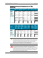
1
Configuration Manual
Version 11.00 - November 2011
Production & Playout Server
XT3 Server - Version 11.00 - Configuration Manual
Copyright
EVS Broadcast Equipment S.A.– Copyright © 2011. All rights reserved.
Disclaimer
The information in this manual is furnished for informational use only and subject to
change without notice. While every effort has been made to ensure that the information
contained in this user manual is accurate, up-to-date and reliable, EVS Broadcast
Equipment cannot be held responsible for inaccuracies or errors that may appear in this
publication.
Improvement Requests
Your comments will help us improve the quality of the user documentation. Do not
hesitate to send improvement requests, or report any error or inaccuracy on this user
manual by e-mail to [email protected].
Regional Contacts
The address and phone number of the EVS headquarters are usually mentioned in the
Help > About menu in the user interface.
You will find the full list of addresses and phone numbers of local offices either at the end
of this user manual (for manuals on hardware products) or at the following page on the
EVS website: http://www.evs.tv/contacts.
User Manuals on EVS Website
The latest version of the user manual, if any, and other user manuals on EVS products
can be found on the EVS download center, on the following webpage:
http://www.evs.tv/downloadcenter.
I
EVS Broadcast Equipment S.A. - November 2011
Issue 11.00.C
Table of Contents
1. INTRODUCTION
1.1.
Introduction to the Configuration of EVS Servers
1
1.2.
Introduction to the Manual
3
1.3.
Starting the EVS Server
4
1.4.
Accessing the Web-Based Interface
4
2. MULTICAM SETUP
1
2.1.
Overview of User Interfaces
2.1.1.
Overview on the Setup Areas
2.1.2.
Navigability and Commands
2.2.
Configuration Lines
2.2.1.
Chapter Contents
2.2.2.
Launching a Configuration
2.2.3.
Editing a Configuration
2.2.4.
Renaming Configuration Lines
2.2.5.
Exporting and Importing Configuration Lines
2.2.6.
Changing the Position of Configuration Lines
2.2.7.
Copying, Pasting and Deleting Configuration Lines
7
7
7
8
9
10
14
14
2.3.
Server Parameters
2.3.1.
Chapter Contents
2.3.2.
Assigning a Server Facility Name
2.3.3.
Activating and Deactivating the Password Protection
2.3.4.
Setting the Server LAN PC Address
2.3.5.
Setting the Server Date and Time
2.3.6.
Setting the Default Output To VGA/Video
2.3.7.
Configuring Server Raids
16
16
16
17
19
20
21
21
2.4.
Licenses and Maintenance
2.4.1.
Overview on Options Codes Management
2.4.2.
Options Codes Management Window
2.4.3.
Entering and Removing License Codes
24
24
25
27
2.5.
Server Maintenance
2.5.1.
Chapter Contents
2.5.2.
Rebooting the EVS Server
2.5.3.
Hardware Check
2.5.4.
Clearing Video Disks
2.5.5.
Calibrating a Touch Screen
2.5.6.
Importing and Exporting Keyword Files
2.5.7.
Exporting Log Files
29
29
29
29
33
33
33
34
3. MULTICAM CONFIGURATION
3.1.
II
1
Overview on User Interfaces
3.1.1.
Introduction
3.1.2.
Overview on the Multicam Configuration Window
3.1.3.
Navigation and Editing in the Multicam Configuration Window
3.1.4.
Overview on the Setup Menus in the Remote Panel
1
1
4
35
35
35
36
39
40
XT3 Server - Version 11.00 - Configuration Manual
3.1.5.
3.2.
Navigation and Editing in the Setup Menus of the Remote Panel
Server Tab
3.2.1.
Overview
3.2.2.
Video and Reference
3.2.3.
Phase Definition Settings
3.2.4.
Interpolation Settings
3.2.5.
PC LAN Settings
GLOSSARY
41
43
43
44
53
55
56
58
III
XT3 Server - Version 11.00 - Configuration Manual
1.
Introduction
1.1.
Introduction to the Configuration of EVS
Servers
New Configuration Module
The Multicam Setup application is used for configuration and maintenance operations on
EVS video servers. It is also used to select which application to run, since EVS disk
recorders have the ability to run various dedicated applications (Video Server, Slow
Motion, …).
With the release of Multicam 11, a new configuration module has been implemented
aiming at simplifying and clarifying the EVS server management and configuration tasks.
The new configuration module has been developed along the lines presented in this
section.
Consolidation into a Single User Interface
The server can now be fully configured from a single user interface.
The user interface includes:
•
1. Introduction
a setup section presented on one page with two main areas which give access to the
configuration lines and the most used maintenance commands:
1
EVS Broadcast Equipment S.A. - November 2011
•
Issue 11.00.C
a configuration section for each configuration line. It is presented in seven tabs which
easily give access to all configuration parameters:
Simplification of the User Interface
The user interface has been simplified thanks to:
•
the separation of basic and advanced parameters
The most commonly used parameters are displayed in a Basic mode while more
specific parameters are hidden, and can be displayed when you toggle to the
Advanced mode.
•
the filtering of the parameters displayed
The parameters are only displayed when they are applicable to the chassis type, the
video standard and option codes.
Parameter Changes While Server is Running
Changes to most parameters can now be performed and will be taken into account while
the server is running.
Clarification of Audio Configurations
The audio configurations are more open and more easily configurable as it is now possible
to:
•
•
•
modify the audio parameters while the server is running
configure individual outputs for Embedded, Digital and Analog audio.
configure audio monitoring settings directly from the Remote Control panel.
Configuration Available from Server, Web and Remote
Panel
You can configure the EVS server using one of the three available tools:
•
•
2
The server-based application (VGA) features all settings and commands for the setup
and configuration.
The newly designed web-based interface is equivalent to the server-based application
and enables engineers to configure the EVS server remotely.
1. Introduction
XT3 Server - Version 11.00 - Configuration Manual
•
The Remote Control panel now includes:
◦ a technical setup menu that gives access to the most commonly used technical
settings.
◦ an operational setup menu that only provides operational settings.
The following table gives an overview on the features available in each user interface:
EVS Server Configuration
Setup Window
Configuration Window
Technical
Yes
Yes
(tabs 1-6)
(tab 7)
Server-Based
Application
Yes
Web-Based
Application
Yes
Yes
Yes
(except some Tools
commands)
(tabs 1-6)
(tab 7)
No
Yes
(Technical Setup
F0)
Yes
Remote Panel
1.2.
Settings
Operational
Settings
(Setup Menu
SHIFT+D)
Introduction to the Manual
The XT3 server Configuration manual is the successor of the former Software Technical
Reference manual and Multicam Configuration manual.
Both manuals have been merged into a single manual due to the in-depth reorganization of
the software modules that allow configuring the EVS video servers. The Configuration
manual is server-related.
The Server Configuration manual is organized in two sections:
•
•
A section dedicated to the Multicam Setup window that mainly features:
◦ the configurations lines and their management
◦ the functions related to server administration and maintenance.
A section dedicated to the Multicam Configuration windows that describes all server
configuration parameters that can be defined for each configuration line. The section
includes:
◦ the parameter description itself
◦ other server-related information needed for the configuration
Warning
Please note that this version of the configuration manual is not final. The section
dedicated to the Multicam Configuration window is partial. A complete user
manual will be published in the following weeks.
1. Introduction
3
EVS Broadcast Equipment S.A. - November 2011
1.3.
Issue 11.00.C
Starting the EVS Server
Introduction
When switching on the EVS server, the first step is the PC boot sequence, followed by
the boot of the video I/O boards, and finally the Multicam Setup application is started.
When Starting the EVS Server for the First Time
Before you first use your EVS server, you need to perform the following tasks:
•
•
Define the configuration lines your EVS server should run.
For more information, see section "Configuration Lines" on page 7.
Define the configuration parameters for each configuration line you will need.
In this step, you will define, among others, the channel configuration for the selected
configuration line, as well as audio and video parameters for the EVS server.
For more information, see the section See "Multicam Configuration" on page 35.
When Starting the EVS Server After Initial Configuration
After the initial configuration, you will select a configuration line and press ENTER to run
the server in this configuration. See also the section See "Launching a Configuration" on
page 7. As soon as the EVS server is launched in a configuration, it starts the loop
recording process.
1.4.
Accessing the Web-Based Interface
Prerequisite
When the EVS server is started, you can access the web-based interface of the Multicam
Setup application for that EVS server from any machine (PC or server) that is on the same
network range as the EVS server. You can use any browser to open the web-based
interface.
Procedure
To be able to open the web-based interface in a browser, you need to know the IP address
of the PC LAN of the EVS server. For more information, see section "Setting the Server
LAN PC Address" on page 19.
In your browser, enter the following URL: http://xxx.xxx.xxx.xxx/cfgweb/ where the
crosses correspond to the PC LAN IP address of the EVS server you want to access.
4
1. Introduction
XT3 Server - Version 11.00 - Configuration Manual
2.
Multicam Setup
2.1.
Overview of User Interfaces
2.1.1.
Overview on the Setup Areas
General Description
The Multicam Setup window is the window that first opens when the Multicam Setup
application is launched. It is displayed when the EVS server is started but does not run a
given configuration yet.
The Multicam Setup window allows users to:
•
•
•
view and manage the various configuration lines.
perform some administration and maintenance tasks on the EVS server.
view summary information on the EVS server and the selected configuration line.
This is available in both server-based and web-based Multicam Setup applications.
Both user interfaces include the same features, except that the Tools menu offers less
commands in the web-based user interface.
2. Multicam Setup
1
EVS Broadcast Equipment S.A. - November 2011
Issue 11.00.C
User Interfaces
The Multicam Setup window contains six areas highlighted and described below.
These areas contain similar information in both web-based and server-based applications:
The following screenshot presents the Multicam Setup window in the server-based
application:
The following screenshot presents the Multicam Setup window in the web-based
interface:
2
2. Multicam Setup
XT3 Server - Version 11.00 - Configuration Manual
Description of the Areas
The table below describes the various parts of Multicam Setup window:
#
Name of area
Description
1.
Title bar
The title bar displays the following information:
•
•
•
•
2.
Configuration Lines
Multicam version
server facility name (if any)
chassis type
server serial number
This area shows all configurations the EVS
server can run.
For more information, see sectionSee
"Configuration Lines" on page 7
3.
Tools
This area provides the main commands for
server administration and maintenance.
For more information, click the Tools command
below to go to the dedicated sections in the
Multicam Setup chapter:
•
•
•
•
•
•
•
•
•
•
•
•
•
•
4.
Configuration Summary
Import/export configuration lines
Assign server facility name
Import/export keyword files
Export log files
Options code management
Hardware check
Raid Configuration
Set LAN PC address
Set date and time
Clear video disks
Touch screen calibration
Default to VGA
Reboot
Enable password for technical settings
This area shows a summary of the server
parameters for the configuration line selected in
the Configuration Lines area.
The summary displays the following
information:
1. codec type - bitrate - video standard
2. based config - INs/OUTs - No. audios
3. SDTI No. - server name - server type
2. Multicam Setup
3
EVS Broadcast Equipment S.A. - November 2011
Issue 11.00.C
#
Name of area
Description
5.
Task bar
(Server-based application) displays commands
for the main actions in the window.
For more information, See "Navigability and
Commands" on page 4.
5'.
Status bar
(Web-based application) displays:
•
•
•
6.
Server Information
displays the following information on the EVS
server:
•
•
•
2.1.2.
the Multicam Setup application status
the date and time of the last refresh
the Refresh button
genlock status (OK or bad)
timecode and timecode status (OK or bad)
IP address of the LAN PC
Navigability and Commands
In the Server-Based Application
General Navigability
The following table presents the general commands to navigate in the Multicam Setup
window:
4
Command description
Command key
Moving the cursor to the first item of the Tools menu
F9
Moving the cursor to the first configuration line
ESC
Moving down in the list of editable items
(configuration lines and Tools commands)
TAB
Moving up in the list of editable items
SHIFT+TAB
Displaying a Help window that gives a summary of
the commands
F1
2. Multicam Setup
XT3 Server - Version 11.00 - Configuration Manual
Configuration Lines
In the Configuration Lines area, a configuration line is highlighted when it is selected.
The main commands for configuration line management are presented below:
Command description
Command key
Moving up in the list of configuration lines
UP ARROW
Moving down in the list of configuration lines
DOWN ARROW
Starting the server with a given configuration line
ENTER on selected line.
Entering the Configuration window to edit the settings
related to a selected line
F8
Renaming a configuration line
CTRL + F1
Deleting a configuration line
CTRL + DELETE
More commands on configuration lines are explained in the section See "Configuration
Lines" on page 7.
Tools Menu
Command description
Command key
Selecting a tool command
Pressing the shortcut key
(between brackets in the
command name)
Calling a tool command
ENTER on the selected
command
In the Web-Based Interface
Note
To be sure that changes have been taken into account in the web-based
interface, refresh regularly the page by clicking the Refresh button
Status bar.
in the
Configuration Lines
Command description
Command icon
Renaming the configuration line
Entering the Configuration window to edit the settings related the
configuration line
Deleting the configuration line
Starting the server with the corresponding configuration line
2. Multicam Setup
5
EVS Broadcast Equipment S.A. - November 2011
Issue 11.00.C
Tools Menu
To call a Tools command, simply click on the command in the Tools menu. This will open
the corresponding window.
6
2. Multicam Setup
XT3 Server - Version 11.00 - Configuration Manual
2.2.
Configuration Lines
2.2.1.
Chapter Contents
The table below presents the topics of this section and shows whether the feature
described is available from the web-based interface and/or from the server-based
interface.
2.2.2.
Features
Server-Based
Web-Based
"Launching a Configuration" on page 7
Yes
Yes
"Editing a Configuration" on page 8
Yes
Yes
"Renaming Configuration Lines" on page 9
Yes
Yes
"Exporting and Importing Configuration Lines" on page
10
Yes
Yes
(one by one)
"Changing the Position of Configuration Lines" on page
14
Yes
Yes
(indirectly)
"Copying, Pasting and Deleting Configuration Lines" on
page 14
Yes
Yes
(indirectly)
Launching a Configuration
Introduction
When the EVS server has initialized, the Multicam Setup window stays open, by default,
until the operator selects the requested configuration line and launches it.
How to Manually Launch a Configuration
In the Server-Based Application
To start a configuration in the server-based application, proceed as follows:
1. Press the UP ARROW or DOWN ARROW key to respectively move up and down in
the list of configuration lines until the requested line is highlighted.
2. Press ENTER to run the configuration line on the EVS server.
In the Web-Based Interface
To start a configuration in the web-based interface, click the Launch icon
configuration line you want to launch.
2. Multicam Setup
next to the
7
EVS Broadcast Equipment S.A. - November 2011
Issue 11.00.C
Automatic Launch
From the server-based application, it is possible to set the server so that the last used
configuration line is automatically launched when the Multicam Setup window has stayed
open for five seconds.
To activate the automatic launch, press F7 on the requested configuration line in the
Multicam Setup menu before launching this configuration. This configuration line is now
highlighted in black (no longer in green) to indicate the automatic launch is active. The last
used configuration line will then be launched automatically after a five seconds' delay the
next time the EVS server will be restarted.
If you want to change the configuration line to be launched, you need to rapidly hit a key on
the keyboard connected to the EVS server within five seconds after the Multicam Setup
window has been displayed. Then, the Multicam Setup window will stay open and let you
select another configuration.
2.2.3.
Editing a Configuration
How to Edit a Configuration
When the operator hits a key on the keyboard connected to the EVS server (within five
seconds if the automatic launch of a configuration is active), the Multicam Setup window
stays open, and the operator can select and enter the selected configuration to edit it.
In the Server-Based Application
To edit a configuration line in the server-based application, proceed as follows:
1. Press the UP ARROW or DOWN ARROW key to respectively move up and down in
the list of configuration lines until the requested line is highlighted.
2. Press F8.
The Configuration window opens. See the section See "Multicam Configuration" on
page 35 to edit the configuration parameters.
3. When the configuration is defined for a given line, press ALT+A in the Configuration
window to validate the changes
4. Press ESC to come back to the Setup window.
In the Web-Based Interface
To edit a configuration line in the web-based interface, proceed as follows:
1. Click the Edit icon
for the configuration line you want to configure.
The Configuration window opens. Refer to the section See "Multicam Configuration"
on page 35 to edit the configuration parameters.
2. When the configuration is defined for the given line, click Apply to validate, and then
Quit to come back to the Setup window.
8
2. Multicam Setup
XT3 Server - Version 11.00 - Configuration Manual
Invalid Configuration
Invalid configuration lines are easily detected in the server-based application:
•
•
2.2.4.
When a configuration line becomes invalid, a red exclamation mark <!> is displayed
next to the configuration line in both server-based and web-based interfaces.
When the operator presses F8 to edit the configuration line in the server-based
application, a popup window indicates the line is invalid. When the operator
acknowledges the message, the pages including the invalid parameters are displayed
with the invalid parameters selected.
Renaming Configuration Lines
Introduction
When the EVS server is delivered, default names are assigned to the configuration lines.
You can change them as explained below.
In the Server-Based Application
To rename the configuration line in the server-based application, proceed as follows:
1. Press the UP ARROW or DOWN ARROW key to respectively move up and down in
the list of configuration lines until the requested line is highlighted.
2. Press CTRL+F1.
The line if highlighted in pink and the cursor blinks on the first character.
3. Type the new name for the configuration line taking the following into account:
◦ The space bar allows you to delete the selected character.
◦ The LEFT ARROW and RIGHT ARROW keys allow you to move the cursor
position on the line.
4. Press ENTER to validate the new name.
The new name is assigned to the configuration line and reflected in all user interfaces.
In the Web-Based Interface
To rename the configuration line in the web-based application, proceed as follows:
1. Click the Rename button
next to the configuration line you want to rename.
2. In the Rename dialog box, type the new configuration name.
3. Click OK.
The new name is assigned to the configuration line and reflected in all user interfaces.
2. Multicam Setup
9
EVS Broadcast Equipment S.A. - November 2011
2.2.5.
Issue 11.00.C
Exporting and Importing Configuration Lines
How to Export Configuration Lines
In the Server-Based Application
Note
In the server-based application, the configuration lines are exported onto a USB
key. For this reason, you first need to insert a USB key on the USB port located
on the front panel of the EVS server.
To export configuration lines from an EVS server in the server-based application, proceed
as follows:
1. In the Multicam Setup window, press P to call the Export Configuration Lines
command. The Export Configuration Lines window opens:
◦ The left pane allows the selection of the configuration lines to be exported
◦ The right pane allows the selection of the location where the export folder will be
created on the USB key.
2. If requested, change the name of the folder the configuration lines will be exported to:
◦ By default, the folder name, displayed in the upper right corner, follows the
pattern: <server facility name_current date> where the date has the YYMMDD
format.
◦ To change the export folder name, type the requested name. You can do this any
time in the procedure.
3. If requested, change the selection of configuration lines selected for export on the left
pane:
◦ By default, all configuration lines are selected for export (orange font).
◦ To deselect a line, use the UP ARROW or DOWN ARROW key to highlight it in
green, and press SPACEBAR. The deselected lines turn white.
4. Press TAB to shift the focus to the right pane.
10
2. Multicam Setup
XT3 Server - Version 11.00 - Configuration Manual
5. If requested, change the location where the export folder will be created:
◦ By default, the export folder is created on the root of the USB key, so <Root> is in
a green font.
◦ To change the folder where the export folder will be created, highlight the
requested folder. The last highlighted folder will be considered as the requested
location.
6. To start the export process, press ENTER.
7. When the selected lines are exported (as a .lin file) on the USB key, a message opens
to confirm the export. Click OKto acknowledge the message.
In the Web-Based Interface
Note
In the web-based application, it is only possible to export configuration lines one
by one.
To export configuration lines from an EVS server in the web-based application, proceed as
follows:
1. From the Multicam Setup window, click Export configuration lines in the Tools menu.
The Export configuration line window opens:
2. Click Export next to the configuration line you want to export.
3. In the File Download dialog box, click Save.
4. Select the location where you will save the export configuration file (.lin file) and, if
requested, change the file name.
5. Click Save.
The export file is saved at the requested location.
If you want to export several configuration lines, repeat this operation for all requested
configuration lines.
2. Multicam Setup
11
EVS Broadcast Equipment S.A. - November 2011
Issue 11.00.C
How to Import Configuration Lines
In the Server-Based Application
Note
In the server-based application, the configuration lines are imported from a USB
key. For this reason, you first need to insert into EVS server (USB port on the
front panel) the USB key that contains the .lin file to be imported .
Warning
If the EVS server is password-protected, you should deactive the password
protection. Otherwise, you will only be able to import the operational settings of
the configuration lines selected for import.
1. In the Multicam Setup window, press M to call the Import Configuration Lines
command.
A message informs you that the USB key is being parsed for the detection of folders
containing configuration files (.lin files).
2. The Import Configuration Lines window opens:
◦ The left pane allows the selection of the folder containing the configuration files to
be imported.
◦ The right pane allows the selection of the configuration lines to be imported onto
the EVS server.
3. On the left pane, use the UP ARROW or DOWN ARROW key to highlight the folder
that contains the configuration file you want to import.
When the folder is selected, the right pane shows:
◦ in orange the configuration lines that will be imported to the server.
The lines are imported onto the same position and with the same name as in the
export file.
◦ in white the configuration lines that will remain unchanged on the EVS server (no
import).
4. Press TAB to shift the focus to the right pane.
12
2. Multicam Setup
XT3 Server - Version 11.00 - Configuration Manual
5. If requested, deselect lines you do not want to import:
◦ By default, all configuration lines present in the .lin file will be imported onto the
EVS server.
◦ To deselect a line, use the UP ARROW or DOWN ARROW key to highlight it in
green, and press SPACEBAR. The deselected lines turn light grey.
6. Press ENTER to validate the selection of configuration lines to import.
A warning message informs you about which configuration lines will be imported, and
tells the next screen will allow you to select which settings to replace.
7. Select 'Yes' using the RIGHT ARROW, and press ENTER.
8. In the Select settings to replace window, select the type of settings you want to import
for the selected configuration lines:
a. Press SPACEBAR to select or deselect a settings type.
b. Press TAB to move to the next settings type.
c. Repeat these steps for all settings types you want to import.
9. Press ENTER to start the import process.
In the Web-Based Interface
Note
In the web-based application, it is only possible to import configuration lines one
by one.
To import configuration lines onto an EVS server in the web-based application, proceed as
follows:
1. From the Multicam Setup window, click Import configuration lines in the Tools menu.
The Import configuration line window opens.
2. Click Select next to the top field and select the configuration file you want to import.
3. Tick the configuration line to be replaced on the EVS server.
4. Click Import.
The configuration line is imported with its original name onto the selected configuration
line on the EVS server.
2. Multicam Setup
13
EVS Broadcast Equipment S.A. - November 2011
2.2.6.
Issue 11.00.C
Changing the Position of Configuration Lines
In the Server-Based Application
To move a configuration line up in the list in the server-based application, proceed as
follows:
1. Press the UP ARROW or DOWN ARROW key to respectively move up and down in
the list of configuration lines until the requested line is highlighted.
2. Do one of the following:
◦ To move the selected line up, press CTRL + UP ARROW.
◦ To move the selected line down, press CTRL + DOWN ARROW.
In the Web-Based Interface
The feature to move configuration lines up and down in the list of configuration lines is not
available as such in the web-based application.
You can however use the import and export feature to change the position of lines in the
list of configuration lines.
2.2.7.
Copying, Pasting and Deleting Configuration
Lines
How to Copy/Paste Configuration Lines
In the Server-Based Application
Warning
Note that copying a line onto another position will erase the configuration on the
selected position.
To copy and paste a configuration line in the server-based application, proceed as follows:
1. Press the UP ARROW or DOWN ARROW key to respectively move up and down in
the list of configuration lines until the requested line is highlighted.
2. Press CTRL+C to copy the line to the clipboard.
3. With the UP ARROW and DOWN ARROW keys, move to the position where you
want to copy the line.
4. Press CTRL + V to paste the line to the selected position.
5. Press ENTER to confirm that you agree to replace the former configuration line by the
copied one on the selected position.
14
2. Multicam Setup
XT3 Server - Version 11.00 - Configuration Manual
In the Web-Based Interface
The feature to copy and paste configuration lines is not available as such in the webbased application.
You can however use the import and export feature to change the position of lines in the
list of configuration lines.
How to Delete Configuration Lines
Warning
When you delete a configuration line, the line is automatically be deleted,
without prior warning message.
In the Server-Based Application
To delete a configuration line in the server-based application, proceed as follows:
1. Press the UP ARROW or DOWN ARROW key to respectively move up and down in
the list of configuration lines until the requested line is highlighted.
2. Press CTRL+D to delete the line.
The line is directly deleted.
In the Web-Based Interface
To delete a configuration line in the web-based interface, click the Delete icon
the configuration line you want to delete.
next to
The configuration line is directly deleted.
2. Multicam Setup
15
EVS Broadcast Equipment S.A. - November 2011
2.3.
Server Parameters
2.3.1.
Chapter Contents
Issue 11.00.C
The table below presents the topics of this section and shows whether the described
features are available from the web-based interface and/or from the server-based
interface.
2.3.2.
Commands
Server-Based
Web-Based
"Assigning a Server Facility Name" on page 16
Yes
Yes
"Activating and Deactivating the Password Protection"
on page 17
Yes
No
"Setting the Server LAN PC Address" on page 19
Yes
No
"Setting the Server Date and Time" on page 20
Yes
No
"Setting the Default Output To VGA/Video" on page 21
Yes
No
"Configuring Server Raids" on page 21
Yes
No
Assigning a Server Facility Name
Introduction
You can assign a facility name to the EVS server. It allows the identification of the EVS
server with a dedicated name, besides the server's serial number. This name is
independent from any configuration.
The server facility name differs from the server net name, which can vary from a
configuration to the other as it is defined in the configuration parameters.
The server facility name is displayed in the title bar of the Multicam setup and
configuration windows, as well as on the OSD (on-screen display).
In the Server-Based Application
To assign a server facility name in the server-based application, proceed as follows:
1. In the Multicam Setup window, press F to call the Assign server facility name
command. A dialog box opens:
2. Type the server facility name and press ENTER.
The facility name is directly assigned and displayed in the title bar, as well as on the OSD.
16
2. Multicam Setup
XT3 Server - Version 11.00 - Configuration Manual
In the Web-Based Interface
To assign a server facility name in the web-based interface, proceed as follows:
1. From the Multicam Setup window, click Assign server facility name in the Tools
menu. A dialog box opens:
2. Type the server facility name and press OK.
The facility name is directly assigned and displayed in the title bar, as well as on the OSD.
2.3.3.
Activating and Deactivating the Password
Protection
Activating the Password on the EVS Server
Introduction
The administrator can protect the EVS server with a password. This password protection
prevents unauthorized users from changing configuration settings. It does not prevent
from using operational commands.
The password protection can only be activated and deactivated from the server-based
application.
The password protection has the following impact on the various user interfaces:
•
•
The password is required to apply changes to configuration parameters in the serverbased application and in the web-based interface.
On the Remote Panel, the Technical Setup menu is not available.
How to Activate a Password on the EVS Server
To activate a password on the EVS server, proceed as follows:
1. In the Multicam Setup window, press W to call the Enable password command. A
warning message opens.
2. Read the warning message carefully. Press the RIGHT ARROW key to select 'Yes'
and press ENTER to activate the password protection.
The password protection is directly active in all user interfaces, for all configuration
parameters on all configuration lines.
2. Multicam Setup
17
EVS Broadcast Equipment S.A. - November 2011
Issue 11.00.C
Enabling Changes to Configuration Parameters
In the Server-Based Application
When the password protection is active, the following message is displayed in red at the
top of each configuration tab in the Multicam Configuration window:
To enable changes in the configuration parameters during the session, you will be
prompted for the password the first time you will save changes to configuration
parameters in a session.
In the Web-Based Interface
When the password protection is active, the Multicam Configuration window is
completely dimmed and a close lock icon is displayed at the top of the window:
To enable changes in configuration parameters during the browser session, proceed as
follows:
1. Click the Lock icon .
2. Enter the password on the dialog box that is displayed.
3. Press OK.
The close lock icon changes to an open lock icon
modified and saved for the browser session.
, and the parameters can be
How to Deactivate the Password on the EVS Server
Once the password protection is active, it can only be deactivated from the server-based
application as follows:
1. In the Multicam Setup window, press W to call the Enable password command.
A message opens to warn you that you are about to remove the password protection:
2. Press the RIGHT ARROW key to select 'Yes' and press ENTER
3. Type the password in the dialog box that opens, and press ENTER to validate:
The password protection is directly removed from all user interfaces.
18
2. Multicam Setup
XT3 Server - Version 11.00 - Configuration Manual
2.3.4.
Setting the Server LAN PC Address
Introduction
The MTPC board of an EVS server allows interaction with other EVS hardware on a setup
via the LAN PC address. The port #1 of the MTPC board is used. The communication is
established through telnet or FTP access. XNet Monitor will also use the LAN IP
connection to transfer the monitoring data.
Note
You can only define the settings associated with the LAN PC address from the
server-based application.
Settings
The MTPC board connection settings are described in the table below:
Setting
Description
IP Address
Specifies the IP address to connect to the port #1 of the MTPC board on
the server. The IP addresses 0.0.0.0 and 255.255.255.255 are not
allowed.
Subnet Mask
Specifies the range of logical addresses within the address space
assigned to the MTPC board connection.
Default
Gateway
Specifies the IP address of the router on the network that the MTPC
board can use as an access point to external networks.
How to Set the LAN PC
To set up the LAN PC on the EVS server, proceed as follows:
1. In the Multicam Setup window, press L to call the Set LAN PC address command.
The following window opens:
2. In this window, type the IP address, subnet mask, and default gateway using the TAB
key to move from one field to the other.
3. Press ENTER to validate the definition of the LAN PC settings.
The LAN PC settings will automatically be taken into account when you will launch a
configuration line.
2. Multicam Setup
19
EVS Broadcast Equipment S.A. - November 2011
2.3.5.
Issue 11.00.C
Setting the Server Date and Time
Introduction
The Set Date and Time command allows you to adjust the system time & date from the
Multicam Setup window in the server-based application. This is not available in the webbased interface.
Note
When you have just launched a configuration, a window displaying the system
date and time gives you another opportunity to modify these parameters.
Supported Formats
The supported date format is DD-MM-YYYY, as shown in the example below:
•
15-03-2011 for March 15, 2011
The supported time format is hh:mm:ss, as shown in the example below
•
22:58:00 for 22 h 58 min 00 sec (24-hour display)
A warning message will inform you if the format you try to use is not valid.
How to Set the System Date and Time
To set up the system date and time from the Multicam Setup window, proceed as follows:
1. In the Multicam Setup window, press T to call the System date and time command.
The following window opens:
2. In this window, type:
◦ the date in the DD/MM/YYYY format
◦ the time in the hh:mm:ss format (24-hour display)
using TAB to move from one field to the other.
3. Press ENTER to apply the changes to the system date and time.
The date and time you have entered here will automatically be taken into account when
you launch a configuration.
20
2. Multicam Setup
XT3 Server - Version 11.00 - Configuration Manual
2.3.6.
Setting the Default Output To VGA/Video
Introduction
Between the PC boot and the I/O boot, the video driver is loaded. The Default Output to
VGA/Video command allows you to switch the video display from and to one of the
following modes:
•
•
VGA mode
B&W video mode. This mode sends a video CVBS output on the VGA connector,
which allows the VGA screen to be displayed on a standard composite video monitor
using the VGA <==> BNC adapter provided with the unit.
Note
When a configuration has been launched, you can still switch from one mode to
the other with ALT + BACKSPACE.
How to Change the Default Output
By pressing E, the shortcut key to the Default Output command, the default output will
automatically toggle to one mode to the other.
The parameter displayed on the Multicam Setup window corresponds to the active value.
This means that when the parameter displayed is 'Default to VGA', the active mode is the
VGA mode.
2.3.7.
Configuring Server Raids
Introduction
When the EVS server is started, the server raids are automatically detected, and built
based on the default settings described in the 'Default Raid Configuration' section below.
You can view the default raid configuration and modify it from the Raid Configuration
window. This window is only available in the server-based application.
Note
Only SAS drives from EVS can be used as they are specifically configured to
work with EVS video servers.
2. Multicam Setup
21
EVS Broadcast Equipment S.A. - November 2011
Issue 11.00.C
Overview on the Raid Configuration Window
The Raid Configuration window is available from the Multicam Setup window, when
pressing R to call the Raid Configuration command in the Tools menu:
The Requested Configuration area, in the upper part of the window, displays the default
raid configuration. You can modify the default raid configuration in this area. You will find
more information on editable parameters below.
The Current Configuration area, in the lower part of the Raid Configuration window,
provides raid and disk status information..
Default Raid Configuration
At the first start, the software builds the raids using the following settings:
•
•
If internal and external storage are detected, both are used.
(5+1) raid configuration with a maximum of 5 spares is used. First, all the raids are
built. The remaining disks are used as spare disks. The construction of raids starts
with internal arrays and carries on with external arrays. A raid can be created across
several hardware arrays.
Requested Raid Configuration
Overview
In the Requested Raid Configuration, you can modify the following parameters in the
default raid configuration:
•
•
•
Use of internal and/or external storage.
Use of spare disks.
Number of raids to be used.
To modify one of these parameters, pressing TAB to select the requested field, and
SPACE BAR to select the requested value, or type the requested value.
22
2. Multicam Setup
XT3 Server - Version 11.00 - Configuration Manual
Field Description
The following table describes the fields editable in the Requested Configuration area in the
Raid Configuration window. The fields are described in the sequence they are highlighted
when using the TAB key.
Field Name
Description
Storage type
Specifies which storage type you will use. When both
storage types are available, the following values are
possible:
•
•
•
Number of raids
Internal only
External + Internal
External only
Specifies the number of raids you want to use.
Type the number of raids you want to use.
Raid configuration type Specifies the raid configuration type.
The software is able to handle two raid organizations:
•
•
(4+1): raid of 5 disks
(5+1): raid of 6 disks
Current Raid Configuration
This area is used to display the raid status for the selected configuration when the EVS
server is running a configuration.
2. Multicam Setup
23
EVS Broadcast Equipment S.A. - November 2011
Issue 11.00.C
2.4.
Licenses and Maintenance
2.4.1.
Overview on Options Codes Management
Introduction
To run a software application and/or specific software options, not only the software itself
is required but also a license key (called 'license code' in Multicam), which is unique for
every option on every system.
This license keys can be temporary, be valid only until a defined deadline for
demonstration purposes, or be permanent with no time limit.
The license keys are managed from the Options codes management window. This
window is available in both the server-based application and the web-based interface.
Note
When a temporary license code is about to expire within two weeks or is expired,
the system will warn the operator when the Multicam Setup window opens.
Accessing the Options Codes Management Window
To open the Options codes management window in the server-based application, press O
from the Multicam Setup window.
To open the Option codes management window in the web-based interface, click Options
code management in the Tools menu from the Multicam Setup window.
24
2. Multicam Setup
XT3 Server - Version 11.00 - Configuration Manual
2.4.2.
Options Codes Management Window
In the Server-Based Application
The window features three areas which contains the information mentioned below:
Area
Description
Upper area
List of key settings related to the EVS server:
•
•
•
•
•
•
Central area
System ID: ID code of the hardware key, necessary for license
code calculation.
Serial number: Serial number of the mainframe, also written on
the back plate of the mainframe.
User: The user name is a label for information's sake only.
Chassis: Type of mainframe. If this value is wrong, audio and
video routing inside the system will not work properly.
PSU type: Type of CPU installed on the chassis: standard or
hot swap.
Key date and time: Expiration date & time for temporary license
codes. Not available when the permanent codes are installed.
All codes valid for the given server chassis.
Next to each code name, the code number, the type of license
(permanent, temporary, demo, or 'not granted'), as well as the
expiration date are mentioned.
Lower area
2. Multicam Setup
Area where you can enter new license codes manually.
The commands on how to import new license code from files are
specified.
25
EVS Broadcast Equipment S.A. - November 2011
Issue 11.00.C
In the Web-Based Interface
The window features two areas which contain the information mentioned below:
Area
Description
Central area
All codes valid for the given server chassisfor which a license
key has been granted and is still valid.
Next to each code name, the code number is mentioned.
Lower area
26
Area where you can enter new license codes manually or upload a
license code file.
2. Multicam Setup
XT3 Server - Version 11.00 - Configuration Manual
2.4.3.
Entering and Removing License Codes
Introduction
When you request new license codes to activate one or more features, you can receive
the license keys from EVS in the form of:
•
•
a xxxxx.COD file (xxxxx = serial number of the server for which this file has been
calculated). You need to apply this file to the EVS server from the Option codes
management window.
a license code that you can type in the Option codes management window.
Once the license codes have been entered, the corresponding options or features are
automatically active when you launch a configuration, without having to reboot the server.
How to Enter Licence Codes from a COD File
In the Server-Based Application
To enter a new license code delivered via a COD file, proceed in one of the following
ways:
1. Copy the .COD file on a USB key that you connect to the USB port of the EVS server.
2. From the Multicam Setup window, press O to open the Options codes management
window.
3. Press simultaneously ALT+ U keys.
OR
1. Copy manually the .COD file to the C:\ drive of the EVS server
2. In the Multicam Setup menu, press O to open the Options codes management
window.
3. Press simultaneously ALT+ F keys.
The license codes will be read from the .COD file and updated into the system. Next to
the line corresponding to the code, the license type, and the expiration date, if any, are
displayed.
In the Web-Based Interface
To enter a new license code delivered via a COD file, proceed as follows:
1. Copy the .COD file onto a drive available from your PC.
2. From the Multicam Setup window, click Options code management in the Tools
menu to open the Options code management window.
3. Click the Browse button, select the .COD file and click Open.
4. Click Submit.
The license codes will be read from the local file and updated into the system.
The lines corresponding to the new codes area added to the code list.
2. Multicam Setup
27
EVS Broadcast Equipment S.A. - November 2011
Issue 11.00.C
How to Enter License Codes with a Key Number
In the Server-Based Application
To enter a new license code delivered via a key number, proceed as follows:
1. From the Multicam Setup window, press O to open the Options codes management
window.
2. Type the code you have received. It will automatically be typed in the the Validation
Code field:
3. Press ENTER.
Next to the line corresponding to the activated codes, the license type, and the expiration
date, if any, are displayed.
In the Web-Based Interface
To enter a new license code delivered via a key number, proceed as follows:
1. From the Multicam Setup window, click Options code management in the Tools
menu to open the Options code management window.
2. Type the code number in the first field of the Add new code group box:
3. Click Submit.
The lines corresponding to the new codes are added to the code list.
How to Remove a License Code
You can remove a license code from the server-based application. Proceed as follows:
1. Press the UP ARROW and DOWN ARROW keys to move inside the options list and
select the option to be removed.
2. When the option is selected (highlighted in white), press simultaneously CTRL+
DELETE on the keyboard.
3. Confirm the deletion of the option with ENTER.
28
2. Multicam Setup
XT3 Server - Version 11.00 - Configuration Manual
2.5.
Server Maintenance
2.5.1.
Chapter Contents
The table below presents the topics of this section and shows whether the described
features available from the web-based interface and/or from the server-based interface.
2.5.2.
Commands
Server-Based
Web-Based
"Rebooting the EVS Server" on page 29
Yes
No
"Hardware Check" on page 29
Yes
No
"Clearing Video Disks" on page 33
Yes
No
"Calibrating a Touch Screen" on page 33
Yes
No
"Importing and Exporting Keyword Files" on page 33
Yes
No
"Exporting Log Files" on page 34
Yes
No
Rebooting the EVS Server
To reboot the EVS server, press B from the Multicam Setup window, then RIGHT
ARROW and ENTER to validate the action.
2.5.3.
Hardware Check
Overview on the Hardware Check
Purpose
During the hardware check, the following actions are performed:
•
•
Retrieving and checking relevant information related to the various boards installed on
the EVS server
Verifying the validity of the data recorded on the video disk array
The hardware check is only available in the server-based application.
Tip
Hardware check is also used to rebuild the video and audio information after
replacing a faulty disk.
2. Multicam Setup
29
EVS Broadcast Equipment S.A. - November 2011
Issue 11.00.C
Process
The hardware check runs the same steps and checks as the server boot process:
1.
2.
3.
4.
5.
6.
7.
MTPC check
H3X check
Video Codec check
Quad booting
GigE download
Disk check
Data loading
After you have launched the hardware check by pressing H in the Multicam Setup
window, the system automatically starts the test process.
One after the other, the various steps are displayed in the BOOT.H3X window. The test
process is complete when the H3X board is initialized.
At the end of the hardware check, the hardware revisions information is displayed. The
information is logged in the bootwins.log.
Disk Errors and Disconnection
Disconnection
When one disk of the video raid array has sustained errors, Multicam automatically
disconnects that disk and uses the parity disk to rebuild the missing data and provide the
video and audio data blocks to the application. The operator can thus continue working
normally and the message “!Raid” appears on all monitoring outputs.
A message is displayed each time a disk is disconnected:
•
if the faulty disk is a spare disk:
"Warning: a spare disk has been disconnected. The system will
operate normally on the remaining disks.
At the next opportunity
please consider replacing the faulty disk. It can be identified
in the Shift-F5 screen or in the EVS - RAID configuration menu.
[Enter]=Continue"
•
if the faulty disk is contained in a RAID:
"Warning: a disk has been disconnected. The system will operate
normally on the remaining disks. At the next opportunity
please consider replacing the faulty disk. It can be identified
in the Shift-F5 screen or in the EVS - RAID configuration menu.
[Enter]=Continue"
30
2. Multicam Setup
XT3 Server - Version 11.00 - Configuration Manual
Exit
When exiting the Multicam application, a warning will appear to remind the operator that
one disk was disconnected, and invite him to perform a hardware check to repair the video
raid. This is displayed even if a spare disk is available:
•
if the faulty disk is a spare disk:
"Warning: a spare disk has been disconnected. At the next
opportunity please consider replacing the faulty disk. It can
be identified in the Shift-F5 screen or in the EVS - RAID
configuration menu. [Enter]=Continue"
•
if the faulty disk is contained in a RAID:
"Warning: a disk has been disconnected. At the next opportunity
please consider replacing the faulty disk. It can be identified
in the Shift-F5 screen or in the EVS - RAID configuration menu.
[Enter]=Continue"
Restarting
If the Multicam is restarted without the RAID being rebuilt, the following message is
displayed during the bootwins:
•
•
if a spare disk is OK:
[ Bad ] SEAGATE ST9300603SS 3SE10H1J 0006 279GB 02 07
if no spare disk is OK and the RAID is no more complete:
[ Bad ] SEAGATE ST9300603SS 3SE10H1J 0006 279GB 02 07
WARNING !!! Tray XX is missing 1 disk(s) to be complete
Then when entering the Multicam, another message appears, even if a spare disk is
available:
•
if the faulty disk is a spare disk:
"Warning: a spare disk has been disconnected. The system will
operate normally on the remaining disks. At the next
opportunity please consider replacing the faulty disk. It can
be identified in the Shift-F5 screen or in the EVS - RAID
configuration menu. [Enter]=Continue"
•
if the faulty disk is contained in a RAID:
"Warning: a disk has been disconnected. The system will operate
normally on the remaining disks. At the next opportunity please
consider replacing the faulty disk. It can be identified in the
Shift-F5 screen or in the EVS - RAID configuration menu.
[Enter]=Continue"
The operator can press ENTER and operate normally on 4 disks (configuration “4+1”) or
on 5 disks (configuration “5+1”) or exit the software and return to Multicam Setup window
to run a hardware check.
2. Multicam Setup
31
EVS Broadcast Equipment S.A. - November 2011
Issue 11.00.C
Rebuild Process
Introduction
The XT3 server is capable of performing a rebuild process of the RAID. This process can
happen either while the Multicam application is not running (offline process – rebuild is
faster) or while the Multicam application is running (online process – rebuild is slower).
Disconnection Process
As explained in the section "Disk Errors and Disconnection" on page 30, the software will
disconnect a disk that does not behave as expected.
Two options are available for the operator:
•
•
Replace the disconnected disk and restart the server
◦ Start the Multicam application. The rebuild process will start automatically.
◦ Start a hardware check from the EVS menu and launch the rebuild. The process
starts offline. The operator can wait for the rebuild to be completed or cancel it
(that is to say postpone it) and start the Multicam application, in which case the
rebuild carries on in online mode.
The operator can also force the disk to be reconnected by starting the rebuild process
in the hardware check. The process starts offline. The operator can wait for the rebuild
to be completed or cancel it and start the Multicam application, in which case the
rebuild carries on in online mode.
Note
If errors are detected during the rebuild process, a message appears after the
rebuild is complete to warn the operator, and the raid is not considered as
properly rebuilt. In this state, the system will keep working on 4 disks (4+1
configuration) or on 5 disks (5+1 configuration). If you want to run on 5, or 6,
disks again, you can try replacing the disk again and perform another rebuild, or
clear all clips.
If you don’t need to retrieve the clips or the record trains, you don’t need to rebuild the
RAID. In this case, select the 'Clear All Clips' answer when the message with this option
appears in the hardware check.
If you don’t rebuild the RAID array or if you don’t clear clips, the XT3 will keep running on
4, or 5, disks only, and you will see a warning message appearing every time you start or
close the Multicam application. Normal operation can be achieved on 4, or 5, disks, but
then, if another disk fails, the system will hang and all video and audio data will be
definitely lost.
Warning
By default, the online rebuild process takes up 10% of the disk bandwidth. If you
want to change this, contact EVS support.
32
2. Multicam Setup
XT3 Server - Version 11.00 - Configuration Manual
2.5.4.
Clearing Video Disks
This function is used to erase all media from the RAID disk array.
Warning
This will definitely delete all video and audio data, including protected clip and
record trains.
To clear video disks, proceed as follows:
1. In the Multicam Setup window, press C to call the Clearing Video Disks command.
2. Press ENTER.
3. Confirm the deletion with ENTER or cancel with ESC.
2.5.5.
Calibrating a Touch Screen
When a touch screen option is connected and the touch screen option is installed, a touch
screen can be calibrated using this command. If the touch screen is not installed, a
warning message is displayed.
2.5.6.
Importing and Exporting Keyword Files
Introduction
The keyword file is a simple text file with a name of 8 characters and a .KWD extension.
All keyword files must be stored in the C:\LSMCE\DATA\KWD directory of the server. A
sample keyword file (SAMPLE.KWD) is provided by EVS when Multicam is installed.
You can also import and export keyword files to and from the EVS server via a USB key.
You can only perform this action in the server-based application.
How to Import a Keyword File
To import a keyword file, proceed as follows:
1. Save the keyword file you want to import on a USB key, and plug it into the USB port
of the EVS server as the Multicam Setup window is open.
2. In the Multicam Setup window, press K to call the Import/export keyword file
command.
The following dialog box opens:
2. Multicam Setup
33
EVS Broadcast Equipment S.A. - November 2011
Issue 11.00.C
3. If several keyword files are stored on the USB key, press SPACEBAR until the
requested file is selected on the left field.
4. Press ENTER to import the keyword file from the USB key to the EVS server.
5. Press OK to close the message box that appears when the keyword file has been
imported.
6. Remove the USB key.
How to Export a Keyword File
To import a keyword file, proceed as follows:
1. Plug a USB key into the USB port of the EVS server as the Multicam Setup window is
open.
2. In the Multicam Setup window, press K to call the Import/export keyword file
command.
The following dialog box opens:
3. Press ENTER to export the keyword file from the EVS server to the USB key.
4. Press OK to close the message box that appears when the keyword file has been
exported.
5. Remove the USB key.
2.5.7.
Exporting Log Files
When the EVS support team requests the log files to investigate an issue, you can export
the log files to a plugged-in USB key by pressing the X shortcut key from the Multicam
Setup window.
When you call the Export log file command, a .zip file is created on the root folder the
USB key. It contains:
•
•
all files and folders located on C:\LSMCE\DATA folder of the EVS server
an Excel spreadsheet that contains the definition of your configuration lines
After the export action, a message box asks you whether you want to delete the logs on
the EVS server. If you answer 'Yes', the content of the folders C:\LSMCE\DATA\LOG
and C:\LSMCE\DATA\DUMP are deleted.
You can also export log files from XNet Monitor. For more information, refer to the XNet
Monitor user manual.
34
2. Multicam Setup
XT3 Server - Version 11.00 - Configuration Manual
3.
Multicam Configuration
3.1.
Overview on User Interfaces
3.1.1.
Introduction
Preliminary Remarks
Prior to using Multicam, the operator should set all necessary parameters in the Multicam
Configuration window. If clips are stored with certain parameters and the operator wishes
to change them afterwards, those clips and playlists will not change. It is thus important to
set these parameters first.
Most parameters are factory preset, and should not be modified without advice of qualified
EVS staff. Improper values for some parameters will prevent the proper operation of the
system.
General Comparison Between User Interfaces
You can configure the EVS server using one of the three available user interfaces:
•
•
•
Multicam Configuration window in the server-based application
Multicam Configuration window in the web-based application
Technical and Operational Setup menus in the Remote Panel
The Multicam Configuration windows in the server-based and web-based application are
almost identical.
In the Remote Panel, however, only the most used technical settings are available in the
Technical Setup menu, and all operational settings are available in the Operational Setup
menu.
The following table provides an overview on the features available in each user interface:
Configuration Window
Technical
Operational Settings
Settings
Server-Based
Application
Web-Based
Application
Remote Panel
3. Multicam Configuration
Yes
Yes
(tabs 1-6)
(tab 7)
Yes
Yes
(tabs 1-6)
(tab 7)
Yes (partly)
(Technical Setup: F0)
Yes
(Setup Menu: SHIFT+D)
35
EVS Broadcast Equipment S.A. - November 2011
Issue 11.00.C
Overview on Configuration Parameters
The first topic of each section in the Multicam Configuration chapter gives you an
overview on the parameters available in this section, and specifies whether you will find
the parameter:
•
•
in the basic or advanced view in the server-based application and the web-based
interface
in the Technical Setup, Operational Setup, or not at all on the Remote Control panel
The following list provides a hyperlink to all overview topics in the various sections:
•
•
•
•
•
•
•
3.1.2.
Server settings
Channels settings (not currently available)
Network settings (not currently available)
Monitoring settings (not currently available)
Protocol settings (not currently available)
GPI settings (not currently available)
Operations settings (not currently available)
Overview on the Multicam Configuration
Window
Introduction
In the server-based and web-based applications, all server settings related to each
configuration file are now grouped in a single window: the Multicam Configuration window.
When the server is not running a given configuration, the Multicam Configuration window
allows you to define any of the configuration available in the Multicam Setup window.
When the server is running a given configuration, the Multicam Configuration window
allows you to modify the settings of the running configuration.
The Multicam Configuration window is organized in a similar way in both user interfaces:
•
•
•
•
36
It consists of seven tabs.
Each tab contains one or more pages in the server-based application.
Each tab displays all settings on a single page in the web-based application.
The settings on page/tab are organized in field groups having a dedicated name.
3. Multicam Configuration
XT3 Server - Version 11.00 - Configuration Manual
Accessing the Multicam Configuration Window
In the Server-Based Application
To access the Multicam Configuration window from the Multicam Setup window when the
server is not running, proceed as follows:
1. Press the UP ARROW or DOWN ARROW key to respectively move up and down in
the list of configuration lines until the requested line is highlighted.
2. Press F8.
The Multicam Configuration window window opens.
To access the Multicam Configuration window from the Clips or Playlist window when the
server is running, press SHIFT+F2.
In the Web-Based Interface
To access the Multicam Configuration window from the Multicam Setup window when the
server is not running, click the Edit icon
for the configuration line you want to
configure. The Multicam Configuration window opens.
The Multicam Configuration window will directly be displayed on the web-based interface
when the server is running a given configuration. You will directly be able to edit the
settings for the running configuration.
Display Mode
The settings in the Multicam Configuration window have been categorized as basic or
advanced settings depending on whether they are commonly used or not.
Two display modes are consequently available:
•
•
Basic mode
Advanced mode
Selecting the basic mode will hide settings on some pages, or completely hide other
pages.
To change the display mode in the server-based application, press F3.
To change the display mode in the web-based interface, click on the display mode label
or
.
User Interfaces
Server-Based User Interface
The following screenshot presents the 1st tab, and 1st page of the Multicam Configuration
window in the server-based application, shown in Advanced mode:
•
•
•
The title bar displays the selected configuration, and specifies whether the
configuration has been launched (running) or not (not running).
The selected tab is highlighted in rose
The current page and number of pages in the tab are specified in the top right corner.
3. Multicam Configuration
37
EVS Broadcast Equipment S.A. - November 2011
•
Issue 11.00.C
The Display mode (basic or advanced) is specified in the top right corner.
Web-Based User Interface
The following screenshot presents the 1st tab of the Multicam Configuration window in the
web-based application, shown in Advanced mode:
•
•
•
38
The top line displays the name of the selected configuration, and specifies whether
the configuration has been launched (running) or not (not running).
The selected tab is displayed in a lighter gray color.
The Display mode (basic or advanced) is specified on the top line.
3. Multicam Configuration
XT3 Server - Version 11.00 - Configuration Manual
3.1.3.
Navigation and Editing in the Multicam
Configuration Window
In the Server-Based Application
Navigation Commands
The following table presents the commands to navigate in the Multicam Configuration
window:
Command description
Command key
Selecting a given tab
CTRL + tab number
Moving from one tab to the other
(when the tab is selected, i.e. rose highlighted)
LEFT ARROW / RIGHT
ARROW
Moving down/up in the pages of the active tab
PAGE DOWN or PAGE UP
Moving down in the list of editable settings
TAB
Moving up in the list of editable settings
SHIFT + TAB
Toggling between Basic and Advanced display mode
F3
Editing Commands
The following table presents the commands to edit the configuration settings in the
Multicam Configuration window when the field has been selected (using the TAB key).
In text fields, you can directly type the requested value for a selected field. When a field
value has been modified, the field value is in green color as long as the modifications have
not been applied.
Command description
Command key
Increasing the value
(or displaying the next value in the list)
SPACEBAR
Decreasing the value
(or displaying the previous value in the list)
SHIFT+SPACEBAR
Moving the cursor position within a text field
SHIFT+ RIGHT ARROW /
LEFT ARROW
Resetting value of the selected setting
F5
Resetting all values of all settings in the current tab
for the selected configuration
CTRL+F5
3. Multicam Configuration
39
EVS Broadcast Equipment S.A. - November 2011
Issue 11.00.C
Command description
Command key
Resetting all values of all settings in all tabs for the
selected configuration
SHIFT+F5
Applying changes
ALT+A
Leaving without applying changes
ESC, ENTER
In the Web-Based Interface
The navigation and editing commands in the web-based interface are the commonly used
commands in a web-based interface. The command buttons available are the following
ones:
Command description
Command key
Activating the Advanced display mode
Coming back to the Basic display mode
Applying changes
Canceling changes
3.1.4.
Overview on the Setup Menus in the Remote
Panel
Introduction
When you work in LSM mode, the Technical and Operational Setup menus available on
the Remote Panel allow you to define:
•
•
the commonly used technical settings in the Technical Setup menu
all operational settings in the Operational Setup menu.
The values assigned to the settings are saved as soon as they are modified.
Accessing the Technical Setup Menu
To access the Technical Setup menu, proceed as follows:
1. If you are in Playlist mode, press RECORD first to exit this mode.
2. Press F0 to open the Technical Setup menu.
The Technical Setup menu opens on the 1st page.
The Technical Setup menu is divided in sections and subsections, named by Tx.y where
x is the section number, and y the subsection number.
In all sections dedicated to a tab of the Multicam Configuration window in this manual, you
will find an overview table that lists the settings available in the Technical Setup menu, as
well as the sections where you will find them.
40
3. Multicam Configuration
XT3 Server - Version 11.00 - Configuration Manual
Accessing the Operational Setup Menu
To access the Operational Setup menu, proceed as follows:
1. If you are in Playlist mode, press RECORD first to exit this mode.
2. Press SHIFT + MENU to go to the Main menu:
3. Select Setup by pressing SHIFT + D to enter the Operational Setup menu.
The Operational Setup menu is divided in sections and subsections, named by x.y where
x is the section number, and y the subsection number.
3.1.5.
Navigation and Editing in the Setup Menus of
the Remote Panel
Introduction
The way you navigate and edit settings is identical in the Technical Setup menu and
Operational Setup menu. The navigation and editing commands are explained below.
Navigation Commands
The following table presents the commands to navigate in the Setup menus of the Remote
Panel:
Command description
Command key
Moving to another section when you are inside a section
SHIFT+F_ key
corresponding to the
section
Moving to the next page inside a section
F10
When you are on the last page of a section, you will go to the
1st page of the next section.
Moving to the previous page inside a section
F9
When you are on the first page of a section, you will go to the
last page of the previous section.
Exiting the Setup menu
Menu
Scrolling through section pages with the jog wheel
ENTER (when no setting
is selected) + jog
3. Multicam Configuration
41
EVS Broadcast Equipment S.A. - November 2011
Issue 11.00.C
Editing Commands
The following table presents the commands to edit a setting in the Setup menus of the
Remote Panel:
42
Command description
Command key
Selecting a setting in a section
F_ key corresponding to
the requested setting
Modifying the setting value
Turn the jog wheel
Validating the modification to a setting value
ENTER
Restoring the default value for the selected setting
CLEAR + F_ key
corresponding to the
requested setting
Restoring the default values on the entire Setup menu
CLEAR + F0
Validating the changes in the Setup menu
(to answer to the message when you try to leave the menu)
MENU
Cancelling the changes in the Setup menu
(to answer to the message when you try to leave the menu)
CLEAR
Staying in the Setup menu
(to answer to the message when you try to leave the menu)
ENTER
3. Multicam Configuration
XT3 Server - Version 11.00 - Configuration Manual
3.2.
Server Tab
3.2.1.
Overview
Server Tab
The Server tab consists of a single page in the basic or advanced mode in the serverbased application. It covers the settings related to video codecs and standards, time
reference, phase definition, interpolation activation, and PC LAN.
Settings List
The table below presents the settings of the Server tab. It specifies whether the setting is
available:
•
•
in the basic or advanced display mode in the server-based and web-based
applications
in the Technical Setup menu of the Remote Panel
Setting Name
Basic
Advanced
Video and Reference group
P1
P1
Field rate
X
X
Resolution
X
X
Codec
X
X
Bitrate
X
X
Horizontal Res.
LTC Timecode
X
X
Sync PC Time to TC
Genlock
Technical
Setup
X
X
X
X
P1
T1.1
SD
X
X
HD to SD SDI
X
X
P1
T1.2
Vertical interp.
X
X
Four Lines
X
X
Phase Definition group
Interpolation group
P1
PC LAN group
IP Address
X
X
Subnet Mask
X
X
Default Gateway
X
X
3. Multicam Configuration
43
EVS Broadcast Equipment S.A. - November 2011
3.2.2.
Issue 11.00.C
Video and Reference
Video and Reference Settings
Introduction
The Video and Reference settings are available on the Server tab in the server-based
application (1st page) and web-based application. These settings are not available in the
Technical Setup menu of the Remote Panel.
The Video and Reference settings are highlighted in the screenshot of the server-based
application shown below:
Field Rate
Description
Field frequency used (Hz).
Both field rate and resolution give the video standard.
Values
50.00 Hz (PAL) - default
59.94 Hz (NTSC)
59.94 Hz (J)
44
3. Multicam Configuration
XT3 Server - Version 11.00 - Configuration Manual
Resolution
Description
Vertical resolution used (number of white-to-black and black-towhite transitions that can be seen from the top to the bottom of
the picture) (pixel + type).
Both field rate and resolution correspond to the video standard.
With XT3 server, SD and HD video standards can be available
if the relevant license codes are activated.
Values
In SD:
•
•
525i
625i
In HD:
•
•
•
720p
1080i
1080p (only available with code 21 or 22)
Codec
Description
Algorithm used to compress and decompress the video signal.
The codecs available on the EVS server depend on the video
standard used, as well as on the active license codes.
For detailed information on codec availability, see section
"Codec Availability" on page 47.
Values
In SD:
•
•
•
•
Proxy (Jpeg)
Mjpeg (SD)
IMX
DVCPro 50
In HD:
Default values
3. Multicam Configuration
•
•
•
•
•
•
•
•
Mjpeg EVS (HD)
Mjpeg Standard (HD)
Mpeg 2 Intra (HD)
Avid DNxHD 120, 185 or 185x (only in 50 Hz)
Avid DNxHD 145, 220 or 220x (only in 59.94 Hz)
Apple ProRes 422, 422 LT, 422 HQ or 422 HQ (10-bit)
DVCPro HD
AVC-Intra 50 or 100
•
•
•
IMX in SD
Avid DNxHD 120 in HD 50Hz:
Avid DNxHD 145 in HD 59.94 Hz:
45
EVS Broadcast Equipment S.A. - November 2011
Issue 11.00.C
Bitrate
Description
Number of megabits processed per second (Mbps)
The bitrate depends on the codec.
Values
For detailed information on bitrates per codec, see section
"Codec-Related Information" on page 48see section "CodecRelated Information" on page 48.
Horizontal Res. (HD)
Description
Number of white-to-black and black-to-white transitions that can
be seen from the left to the right of the picture (pixels).
The setting value depends on the selected video standard.
Values
For detailed information on horizontal resolution for each video
standard and codec, see section "Codec-Related Information"
on page 48.
Recorded Lines (SD)
Description
Number of lines recorded from the left to the right of the picture.
The setting value depends on the selected video standard.
Values
For detailed information on recorded lines for each video
standard and codec, see section "Codec-Related Information"
on page 48.
LTC Timecode
Description
Longitudinal timecode (timecode information stored on a
separate track from the video) delivered to the EVS server, and
timecode status.
Values
The timecode is given as HH:mm:ss:fr
The timecode status can be 'OK', 'BAD', 'LOST' or 'DRIFT'
(defined by the EVS server).
Sync PC Time to TC
Description
Specifies whether the PC time is synchronized with the
timecode, and how often the synchronization takes place.
Values
Synchronization: 'Yes', 'No'
Frequency: by default 'every 00h15' (not editable)
46
3. Multicam Configuration
XT3 Server - Version 11.00 - Configuration Manual
Genlock
Description
Specifies the type of genlock signal, the status and the frame
synchronizer mode.
Values
Type: 'Blackburst' or 'Tri-Sync' (always 'Blackburst' in SD)
Status: 'OK' or 'BAD' (defined by the EVS server)
Mode: 'Studio' (no correction of a shifted video signal) or
'Resync' (resynchronization of a shifted video signal)
Codec Availability
Codec Availability Depending on License Codes
The following table presents the codec availability for XT3 server depending on the license
code. 'Yes' in the Available column means the codec (and the related licence code) is
available by default:
Codec
Available?
SD
-
IMX
yes
Mjpeg (SD)
yes
DVCPro 50
with code 9
Proxy (Jpeg)
with code 7
HD
-
Mjpeg EVS (HD)
yes
Mjpeg Standard (HD)
yes
Mpeg 2 Intra (HD)
yes
Avid DNxHD
with code 5
Apple ProRes 422, 422 LT,
422 HQ or 422 HQ (10-bit)
with code 6
DVCPro HD
with code 8
AVC-Intra 50 or 100
3. Multicam Configuration
with code 13
47
EVS Broadcast Equipment S.A. - November 2011
Issue 11.00.C
Codec Availability Depending on Codec Board Type
V3X
SD/HD
Codec
SD
Proxy (Jpeg)
X
Mjpeg (SD)
X
IMX
X
DVCPro 50
X
HD
Mjpeg EVS (HD)
X
Mjpeg Standard (HD)
X
Mpeg 2 Intra (HD)
X
Avid DNxHD
X
Apple ProRes 422
X
Apple ProRes 422 LT
X
Apple ProRes 422 HQ
X
Apple ProRes 422 HQ (10-bit)
X
DVCPro HD
X
AVC-Intra 50 or 100
X
Codec-Related Information
Bitrates and Recorded Lines in SD 525i
Codec Type
SD MJPEG Standard
SD IMX (D10)
DVCPro 50
Bitrate
20-100 Mbps
30; 40; 50 Mbps
50 Mbps
Default bitrate
30 Mbps
30 Mbps
50 Mbps
512 lines
(L7-262; L270525)
480 lines
(L23-262; L285524)
Recorded video lines 496 lines
(L16-23; L278-525)
default
480 lines
(L23-262; L286-525)
512 lines
(L7-262; L270-525)
48
3. Multicam Configuration
XT3 Server - Version 11.00 - Configuration Manual
Bitrates and Recorded Lines in SD 625i
Codec Type
SD MJPEG Standard
SD IMX (D10)
DVCPro 50
Bitrate
20-100 Mbps
30;40;50 Mbps
50 Mbps
Default bitrate
30 Mbps
30 Mbps
50 Mbps
608 lines
(L7-310; L320623)
576 lines
(L23-310; L335622)
Recorded video lines 576 lines
(L23-310; L336-623)
default
592 lines
(L15-310; L328-623)
608 lines
(L7-310; L320-623)
Bitrates and Horizontal Resolutions in HD 1080i/1080p
(50 Hz)
HD MJPEG HD MJPEG
EVS
Standard
HD MPEG2 DVCPro AVC
AVC
Intra
HD
Intra 100 Intra 50
Bitrate
(Mbps)
20-360
20-360
20-360
100
111
54
Default
bitrate
100
100
100
100
111
54
Horizontal
Resolution
960
960
960
1440
1920
1440
1152
1152
1152
1280
(default)
1280
(default)
1280 (default)
1372
1372
1372
1440
1440
1440
1536
1536
1536
1600
1600
1600
1920
1920
1920
Codec
3. Multicam Configuration
49
EVS Broadcast Equipment S.A. - November 2011
Issue 11.00.C
AVID
AVID
AVID
DNxHD
DNxHD DNxHD
(10-bit)
120
185
185
Mbps Mbps
Mbps
Apple
ProRes
422 LT
Apple
ProRes
422
Apple
ProRes
422 HQ
Apple
ProRes
422 HQ
(10-bit)
Bitrate
(Mbps)
1-120
121-185 121-185
85
120
185
185
Default
bitrate
120
185
185
85
120
185
185
Horizontal
Resolution
1920
1920
1920
1920
1920
1920
1920
Codec
Bitrates and Horizontal Resolutions in HD 1080i/1080p
(59.94 Hz)
HD MJPEG HD MJPEG
EVS
Standard
HD MPEG2 DVCPro AVC
AVC
Intra
HD
Intra 100 Intra 50
Bitrate
(Mbps)
20-360
20-360
20-360
100
111
54
Default
bitrate
100
100
100
100
111
54
Horizontal
Resolution
960
960
960
1280
1920
1440
1152
1152
1152
1280
1280
(default)
(default)
1280 (default)
1372
1372
1372
1440
1440
1440
1536
1536
1536
1600
1600
1600
1920
1920
1920
Codec
AVID
AVID
AVID
DNxHD
DNxHD DNxHD
(10-bit)
120
185
185
Mbps Mbps
Mbps
Apple
ProRes
422 LT
Apple
ProRes
422
Apple
ProRes
422 HQ
Apple
ProRes
422 HQ
(10-bit)
Bitrate
(Mbps)
1-145
146-220 146-220
102
145
220
220
Default
bitrate
145
220
220
102
145
220
220
Horizontal
Resolution
1920
1920
1920
1920
1920
1920
1920
Codec
50
3. Multicam Configuration
XT3 Server - Version 11.00 - Configuration Manual
Bitrates and Horizontal Resolutions in HD 720p (50 Hz)
HD MJPEG HD MJPEG HD MPEG2
EVS
Standard
Intra
DVCPro AVC
AVC
HD
Intra 100 Intra 50
Bitrate
(Mbps)
20-360
20-360
20-360
100
111
54
Default
bitrate
100
100
100
100
111
54
Horizontal 640
Resolution
640
640
960
1280
960
768 (default) 768 (default) 768
960
960
960
1024
1024
1024
1280
1280
1280 (default)
AVID
AVID
AVID
DNxHD
DNxHD DNxHD
(10-bit)
120
185
185
Mbps Mbps
Mbps
Apple
ProRes
422 LT
Apple
ProRes
422
Apple
ProRes
422 HQ
Apple
ProRes
422 HQ
(10-bit)
Bitrate
(Mbps)
1-120
121-185 121-185
85
120
185
185
Default
bitrate
120
185
185
85
120
185
185
Horizontal
Resolution
1280
1280
1280
1280
1280
1280
1280
Codec
3. Multicam Configuration
51
EVS Broadcast Equipment S.A. - November 2011
Issue 11.00.C
Bitrates and Horizontal Resolutions in HD 720p
(59.94 Hz)
HD MJPEG HD MJPEG HD MPEG2
EVS
Standard
Intra
DVCPro AVC
AVC
HD
Intra 100 Intra 50
Bitrate
(Mbps)
20-360
20-360
20-360
100
111
54
Default
bitrate
100
100
100
100
111
54
Horizontal 640
Resolution
640
640
960
1280
960
768 (default) 768 (default) 768
960
960
960
1024
1024
1024
1280
1280
1280 (default)
AVID
AVID
AVID
DNxHD
DNxHD DNxHD
(10-bit)
120
185
185
Mbps Mbps
Mbps
Apple
ProRes
422 LT
Apple
ProRes
422
Apple
ProRes
422 HQ
Apple
ProRes
422 HQ
(10-bit)
Bitrate
(Mbps)
1-145
146-220 146-220
102
145
220
220
Default
bitrate
145
220
220
102
145
220
220
Horizontal
Resolution
1280
1280
1280
1280
1280
1280
1280
Codec
Note
The dynamic bitrate management system modifies compression tables for each
recorded field to keep the bitrate of the encoded stream as close as possible to
the target. A higher bitrate means better picture quality and less storage
capacity but a higher bandwidth is required. Improper values can lead to exceed
disks performance, causing frozen pictures during playback.
Warning
Some video formats allowed on XT3 hardware create clips that are not
compatible with previous hardware. When an incompatible format is selected, a
warning will be issued at the starting up of the application. In addition, the video
format information displayed on the Server tab of the Multicam Configuration
window indicates any incompatible information.
52
3. Multicam Configuration
XT3 Server - Version 11.00 - Configuration Manual
3.2.3.
Phase Definition Settings
Introduction
The Phase Definition settings are available on the Server tab in the server-based
application (1st page) and web-based application in the advanced mode.
The Phase Definition settings are highlighted in the screenshot of the server-based
application shown below:
SD (Standard Definition)
Description
Allows adjusting the digital main phase of the mainframe for the
standard definition. The value is adjusted by steps of half pixels.
The values depends on the genlock type (See "Video and
Reference Settings" on page 44).
Values
•
•
3. Multicam Configuration
If the Genlock type is set to ‘Blackburst’, the main phase for
SD can be adjusted by steps of half pixels (37 ns) between
- 12000 ns and +15000 ns.
If the Genlock type is set to ‘Tri-Sync’ (only possible in HD
resolutions), the main phase for SD can be adjusted by
steps of half pixels (37 ns) between - 30000 ns and +32000
ns.
53
EVS Broadcast Equipment S.A. - November 2011
Issue 11.00.C
HD to SD SDI / SD SDI to HD
Description
Allows adjusting the secondary phase of the mainframe, that is
to say the relative phase of the:
•
•
HD SDI outputs compared to the phase of the SD SDI
outputs with a 'Blackburst' genlock.
SD SDI outputs compared to the phase of the HD SDI
outputs with a 'Tri-Sync' genlock.
This setting only applies to HD resolutions.
See "Video and Reference Settings" on page 44 for more
information on genlock type.
Values
•
•
If the Genlock type is set to ’BlackBurst’, the secondary
phase for HD to SD SDI can be adjusted by steps of half
pixels (13.5 ns) between - 1000 ns and +1000 ns.
If the Genlock type is set to 'Tri-Sync', the secondary phase
for SD SDI to HD can be adjusted by steps of half pixels
(37 ns) between - 400 ns and +400 ns.
Warning
•
•
54
The SD phase is always adjusted according to the SDI outputs. Internal
CVBS outputs have a delay of 48 x 37 nsec compared to the corresponding
SDI outputs.
The internal CVBS outputs cannot be used to feed directly a vision mixer or
any equipment performing video effects, since the phase of the chroma
subcarrier is not adjustable internally.
3. Multicam Configuration
XT3 Server - Version 11.00 - Configuration Manual
3.2.4.
Interpolation Settings
Introduction
The Interpolation settings are available on the Server tab in the server-based application
(1st page) and web-based application in the advanced mode.
The Interpolation settings are highlighted in the screenshot of the server-based application
shown below:
General Description
The interpolation process aims at reducing the vertical jitter of the pictures that is present
during slow-motion replays. This vertical jitter is actually caused by a violation of the
frame parity when playing back the pictures at less than 100 % speed.
The process consists in re-building new frames to produce a more transparent result.
These frames have to be interpolated, that is calculated by making suitably weighted
averages of adjacent lines.
There are two interpolation modes: 2-line interpolator and the 4-line interpolator:
•
•
The two-line interpolator reduces the vertical jitter, but also the vertical bandwidth.
The four-line interpolator makes it possible to have perfectly steady pictures, but
reduces even more the vertical bandwidth.
Note
All VTRs use interpolation in PLAY VAR mode.
Vertical Interp. (Vertical Interpolation)
Description
Enables or disables the two-line interpolation process.
Values
•
•
3. Multicam Configuration
No (default)
Yes
55
EVS Broadcast Equipment S.A. - November 2011
Issue 11.00.C
Four Lines
3.2.5.
Description
Enables or disables the four-line interpolation process.
Values
•
•
No (default)
Yes
PC LAN Settings
Introduction
The PC LAN settings are available on the Server tab in the server-based application
(1st page) and web-based application in the advanced mode.
The PC LAN settings are highlighted in the screenshot of the server-based application
shown below:
Note
The PC LAN settings are read-only in the Multicam Configuration window. You
can modify them in the Multicam Setup window, using the Set LAN PC
address command. For more information, see section "Setting the Server LAN
PC Address" on page 19.
General Description
The PC LAN settings allow the MTPC board of an EVS server to communicate and
exchange information with other EVS hardware on a setup.
IP Address
56
Description
IP address to connect to the port #1 of the MTPC board on the
server.
Values
The IP addresses 0.0.0.0 and 255.255.255.255 are not allowed.
3. Multicam Configuration
XT3 Server - Version 11.00 - Configuration Manual
Subnet Mask
Description
Range of logical addresses within the address space assigned
to the MTPC board connection.
Default Gateway
Description
3. Multicam Configuration
IP address of the router on the network that the MTPC board
can use as an access point to external networks.
57
EVS Broadcast Equipment S.A. - November 2011
Issue 11.00.C
Glossary
M
Multicam Configuration window
Window in the server-based and web-based Multicam Setup application
from where you can define all configuration parameters.
Multicam Setup application
Term used to refer equally to the server-based or web-based user interface used to set up and configure the EVS servers
Multicam Setup window
Initial Window in the server-based and web-based Multicam Setup application, that is displayed when the EVS server is not running a given configuration yet. It gives access to the configuration lines defined on the
EVS server and to the commonly used maintenance tools.
O
Operational Setup menu
Menu accessible on the Remote Panel using the SHIFT+D keys form the
main menu. It allows users to define operational parameters.
S
Server-Based Multicam Setup application
Server-Based application used to set up and configure the EVS servers.
The short form is 'Server-Based application' in this user manual. This is
accessible from the EVS Server itself when it has been started.
T
Technical Setup menu
Menu accessible on the Remote Panel using the F0 key. It allows users to
define currently used configuration parameters.
W
Web-Based Multicam Setup interface
Web-Based interface used to set up and configure the EVS servers. The
short form is 'Web-Based interface' in this manual. This is accessible
from any machine (PC or server) that is on the same network range as the
EVS server. This can be accessed from a web browser using the
58
Glossary
XT3 Server - Version 11.00 - Configuration Manual
following URL pattern: http://xxx.xxx.xxx.xxx/cfgweb/ where the crosses
correspond to the EVS server IP address of the PC LAN of the EVS
server.
Glossary
59
EVS Broadcast Equipment
Liège Science Park
16, rue Bois St Jean
B-4102 Ougrée
Belgium
Corporate
Headquarters
North & Latin America
Headquarters
Asia & Pacific
Headquarters
Other regional offices
available on
+32 4 361 7000
+1 973 575 7811
+852 2914 2501
www.evs.tv/contact
To learn more about EVS go to www.evs.tv