1
Rosemount Analytical
MicroCEM TS
Analysis Enclosure
Micro Continuous Emission Monitor
Operation & Maintenance Manual
Revision 2.1, Oct. 13, 03
Part Number 1021021-100
Rosemount Analytical
UCEM Continuous Analyzer Transmitter
CONTENTS
Preface
Intended Use Statement …………………………………………………………………………….. 1
Safety Summary ……………………………………………………………………………………… 1
Specifications – Analysis Enclosure: General …………………………………………………….. 4
Specifications – Probe/Sample Handling Enclosure: General ..………………………………… 5
Customer Service, Technical Assistance and Field Service ………..………………………….. 6
Returning Parts to the Factory………………………………………………………………………. 6
Training ………………………………………………………………………………………………... 7
1.
Introduction......................................................................... 1–1
1.1
1.2
1.3
1.3.1
1.3.2
1.3.3
1.3.4
Overview..........................................................................................................................1–1
Time Shared Option.........................................................................................................1–3
Theory of Operation.........................................................................................................1–5
NOx.................................................................................................................................. 1–5
CO ................................................................................................................................... 1–5
O2 .................................................................................................................................... 1–6
SO2.................................................................................................................................. 1–7
2.
Detector Methodologies..................................................... 2–1
2.1
2.1.1
2.1.2
2.1.3
2.2
2.3
Non-Dispersive Infrared (NDIR).......................................................................................2–1
Interference Filter Correlation Method ............................................................................. 2–1
Opto-Pneumatic Method.................................................................................................. 2–2
Overall NDIR Method....................................................................................................... 2–4
Paramagnetic Oxygen Method ........................................................................................2–5
Electrochemical Oxygen Method .....................................................................................2–6
3.
Installation........................................................................... 3–1
3.1
3.2
3.2.1
3.3
3.3.1
3.3.2
3.3.3
3.3.4
3.3.4.1
3.3.4.2
3.3.4.3
3.3.4.4
3.3.4.5
3.3.4.6
3.3.4.7
3.3.4.8
3.3.5
3.3.5.1
3.3.5.2
3.3.5.3
Specifications...................................................................................................................3–1
Process and Calibration Gas Connection........................................................................3–5
Gas Conditioning ............................................................................................................. 3–6
Installation........................................................................................................................3–1
Location ........................................................................................................................... 3–1
Limitations........................................................................................................................ 3–1
Mounting Options............................................................................................................. 3–1
Electrical Connections ..................................................................................................... 3–1
Circular Connector Assembly Instructions.......................................................................3–2
EXT I/O Interface Connector ...........................................................................................3–4
SHU #1 / #2 Interface Connector.....................................................................................3–6
COM Interface Connector................................................................................................3–1
Lan Interface Connector ..................................................................................................3–1
CPU I/O Interface Connector...........................................................................................3–1
SSU Power Connector, T/S units Only ............................................................................3–2
AC Power Connector .......................................................................................................3–2
Analytical Leak Check ..................................................................................................... 3–3
Flow Indicator Method .....................................................................................................3–1
Manometer Method..........................................................................................................3–1
Troubleshooting Leaks ....................................................................................................3–3
4.
Startup and Operation........................................................ 4–1
4.1
4.2
4.2.1
4.2.2
Startup Procedure............................................................................................................4–1
Analyzer Operation .......................................................................................................... 4-1
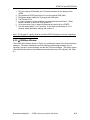
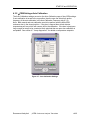
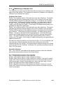
User Interface ...................................................................................................................4-1
µCEM Main Window .........................................................................................................4-2
µCEM Menus ............................................................................................................... 4-4
µCEM Alarms................................................................................................................... 4-6
4.2.3
4.2.4
Rosemount Analytical
µCEM Continuous Analyzer Transmitter
2
CONTENTS
4.2.5
4.2.6
4.2.7
4.3
4.3.1
4.3.2
4.3.3
4.3.4
4.3.5
4.3.6
1818
4.3.7
4.3.8
4.4
4.4.1
4.4.2
4.5
4.6
4.6.1
4.6.2
4.6.3
4.6.4
4.6.5
4.6.6
4.6.7
4.7
4.8
4.8.1
4.8.2
4.8.3
4.9
4.10
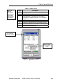
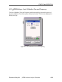
µCEM Login ......................................................................................................................4-8
µCEM Login-Current User Indication................................................................................4-9
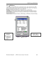
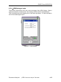
Stream Switching Control ...............................................................................................4-10
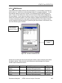
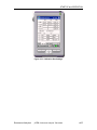
µCEM Settings............................................................................................................... 4-11
µCEM Settings-Range ....................................................................................................4-11
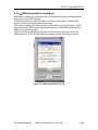
µCEM Settings-Auto Calibration .....................................................................................4-13
µCEM Settings - Auto Calibration Time and Frequency .................................................4-14
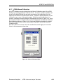
µCEM Settings-Limits ..................................................................................................4-165
µCEM Settings-Calibration Gas....................................................................................4-186
µCEM Settings-Maintenance Mode
4-
µCEM Settings-Manual Calibration.............................................................................4-1918
µCEM Settings-Auto Calibration Dialog .....................................................................4-1519
µCEM Administration ....................................................................................................... 4-2
µCEM Administration-User Settings .................................................................................4-2
µCEM Administration-Auto Logoff ....................................................................................4-3
µCEM Factory and User Settings .................................................................................... 4-4
uCEM Data Logs ............................................................................................................. 4-7
Maximum Log File Size ....................................................................................................4-7
Maximum Number of Log Files.........................................................................................4-7
Log File Name Format ......................................................................................................4-7
Measurement Log File Format..........................................................................................4-8
Calibration Log File Format ..............................................................................................4-8
Alarm Log File Format ....................................................................................................4-10
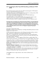
Accessing the Real-Time ACSII Data String via Ethernet TCP/IP (DAS) .....................4-101
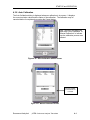
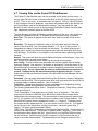
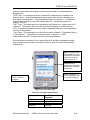
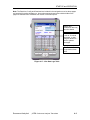
Viewing µCEM Data and Diagnotics with the Pocket PC Web Browser ..........................4-1
Viewing µCEM Data with a Web Browser........................................................................ 4-1
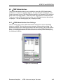
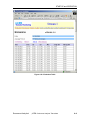
Real-Time Page................................................................................................................4-1
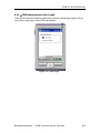
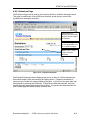
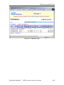
Emissions Page ................................................................................................................4-3
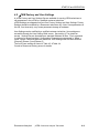
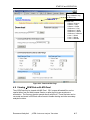
Download Page ................................................................................................................4-6
Viewing µCEM Data with MS Excel ................................................................................. 4-7
Auto Calibration ............................................................................................................... 4-1
5.
Maintenance and Service.................................................... 5-1
5.1
5.2
5.3
5.4
5.5
5.6
5.6.1.1
5.6.1.2
5.6.2
5.6.2.1
5.6.2.2
5.6.2.3
5.6.2.4
5.6.2.5
5.6.2.6
5.6.2.7
5.6.3
5.6.3.1
5.6.3.2
5.6.4
Overview.......................................................................................................................... 5-1
Converter ......................................................................................................................... 5-3
Ozonator .......................................................................................................................... 5-3
Personality Modules ........................................................................................................ 5-3
Detector Assembly........................................................................................................... 5-5
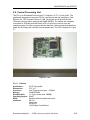
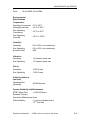
Central Processing Unit ................................................................................................... 5-8
Features........................................................................................................................... 5-8
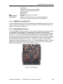
EMBEDDED ENHANCED BIOS:..................................................................................... 5-9
Analog/Digital I/O Board ...................................................................................................5-9
Automatic Calibration..................................................................................................... 5-10
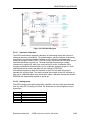
Analog Inputs................................................................................................................. 5-10
Programmable Input Ranges......................................................................................... 5-11
Enhanced Trigger and Sampling Control Signals.......................................................... 5-11
Analog Outputs .............................................................................................................. 5-11
FIFO and 16-Bit Bus Interface ....................................................................................... 5-11
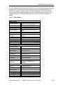
Specifications................................................................................................................. 5-12
PCMCIA Adapter ............................................................................................................5-13
Features......................................................................................................................... 5-14
SOFTWARE FEATURES: ............................................................................................. 5-14
Modem............................................................................................................................5-14
Rosemount Analytical
µCEM Continuous Analyzer Transmitter
3
CONTENTS
5.6.4.1
5.6.5
5.6.5.1
5.6.6
5.6.7
5.6.8
5.6.8.1
5.7
5.7.1
5.8
5.9
Features......................................................................................................................... 5-15
Flash Drive........................................................................................................................5-1
Specifications................................................................................................................... 5-1
Pocket PC.........................................................................................................................5-1
Wireless LAN Adapter ......................................................................................................5-2
500 Watts Power Supply ..................................................................................................5-3
FEATURES...................................................................................................................... 5-3
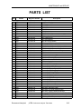
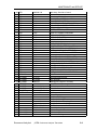
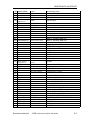
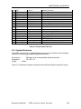
Replacement Parts .......................................................................................................... 5-4
Replacement Part list........................................................................................................5-4
System Enclosure............................................................................................................ 5-9
Trouble LED................................................................................................................... 5-10
6.
µCEM Software .................................................................... 6-1
6.1
6.2
6.3
6.4
µCEM User Interface Software ........................................................................................ 6-1
µCEM Web Server Software............................................................................................ 6-1
Software Development Management .............................................................................. 6-2
µCEM Pocket PC Connection Failure.............................................................................. 6-3
Rosemount Analytical
µCEM Continuous Analyzer Transmitter
4
PREFACE
PREFACE
INTENDED USE STATEMENT
The µCEM Continuous Emission Monitoring Gas Analyzer is intended for use as an
industrial process measurement device only. It is not intended for use in medical,
diagnostic, or life support applications, and no independent agency certifications or
approvals are to be implied as covering such applications.
SAFETY SUMMARY
DANGER is used to indicate the presence of a hazard which will cause severe
personal injury, death, or substantial property damage if the warning is ignored.
WARNING is used to indicate the presence of a hazard which can cause severe
personal injury, death, or substantial property damage if the warning is ignored.
CAUTION is used to indicate the presence of a hazard which will or can cause minor
personal injury or property damage if the warning is ignored.
NOTE IS USED TO INDICATE INSTALLATION, OPERATION, OR MAINTENANCE INFORMATION WHICH
IS IMPORTANT BUT NOT HAZARD RELATED.
DANGER: ALL PERSONNEL AUTHORIZED TO INSTALL,
OPERATE AND SERVICE THIS EQUIPMENT
To avoid explosion, loss of life, personal injury and damage to this equipment
and on-site property, do not operate or service this instrument before reading
and understanding this instruction manual and receiving appropriate training.
Save these instructions.
If this equipment is used in a manner not specified in these instructions,
protective systems may be impaired.
WARNING: DEVICE CERTIFICATION(S)
Any addition, substitution, or replacement of components installed on or in this
device, must be certified to meet the hazardous area classification that the
device was certified to prior to any such component addition, substitution, or
replacement. In addition, the installation of such device or devices must meet
the requirements specified and defined by the hazardous area classification of
the unmodified device. Any modifications to the device not meeting these
requirements, will void the product certification(s).
Rosemount Analytical
µCEM Continuous Analyzer Transmitter
1
PREFACE
DANGER: TOXIC GAS
This device may contain explosive, toxic or unhealthy gas components. Before
cleaning or changing parts in the gas paths, purge the gas lines with ambient air
or nitrogen.
+
WARNING: ELECTRICAL SHOCK HAZARD
POSSIBLE EXPLOSION HAZARD
Do not open while energized. Do not operate without dome and covers secure.
Installation requires access to live parts which can cause death or serious injury.
WARNING: ELECTRICAL SHOCK HAZARD
For safety and proper performance this instrument must be connected to a
properly grounded three-wire source of power.
WARNING: POSSIBLE EXPLOSION HAZARD
Ensure that all gas connections are made as labeled and are leak free. Improper
gas connections could result in explosion and death.
WARNING: TOXIC GAS
This unit’s exhaust may contain hydrocarbons and other toxic gases such as
carbon monoxide. Carbon monoxide is highly toxic and can cause headache,
nausea, loss of consciousness, and death.
Avoid inhalation of the exhaust gases at the exhaust fitting.
Connect exhaust outlet to a safe vent using stainless steel or Teflon line. Check
vent line and connections for leakage.
Keep all tube fittings tight to avoid leaks.
information.
Rosemount Analytical
See Section 3.3.5 for leak test
µCEM Continuous Analyzer Transmitter
2
PREFACE
WARNING: PARTS INTEGRITY AND UPGRADES
Tampering with or unauthorized substitution of components may adversely
affect the safety of this instrument. Use only factory approved components for
repair.
Because of the danger of introducing additional hazards, do not perform any
unauthorized modification to this instrument.
Return the instrument to a Rosemount Analytical Service office for service or
repair to ensure that safety features are maintained.
CAUTION: PRESSURIZED GAS
This unit requires periodic calibration with a known standard gas. It also may
utilize a pressurized carrier gas, such as helium, hydrogen, or nitrogen. See
General Precautions for Handling and Storing High Pressure Gas Cylinders at the
rear of this manual.
CAUTION: HEAVY WEIGHT
USE TWO PERSONS OR A SUITABLE LIFTING DEVICE TO MOVE OR
CARRY THE INSTRUMENT.
Rosemount Analytical
µCEM Continuous Analyzer Transmitter
3
PREFACE
SPECIFICATIONS - GENERAL
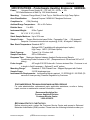
SPECIFICATIONS – Analysis Enclosure: GENERAL
Power:
Universal Power Supply 85 – 125 VAC, 50 – 60 Hz, + 10%, 1000 Watts
Maximum at Start Up. 500 Watts Nominal
MicroProcessor: Intel Celeron processor, 566MHz, 64MB RAM, PC/104 architecture,
Windows NT embedded Platform
Pocket PC: 206MHz, StrongArm processor, 32MB RAM 32 ROM, 240 X 320 pixels LCD,
TFT color, backlit, Wireless LAN optional
Detectors//Number: NDIR (CO), UV (SO2), Paramagnetic (O2), Electrochemical (O2),
Chemiluminscent (NOx) // Up to three in one analyzer
Mounting:
Wall Mount
Area Classification:
General Purpose / NEMA 4X Fiberglass Enclosure Compliant
Compliance's:
CSA (Pending)
Ambient Temperature Range: -300 to 500 Celsius.
Relative Humidity:
5 to 99%
Inputs/Outputs: The complete I/O list with terminal locations is located in section
3.3.4
Digital:
RS-485 Serial Port. (Multi-Drop Network)
RS-232 Serial Port.
LAN, Ethernet 10/100-BaseT
Connectivity Protocols:
HTML (Web Browser) – Status, file transfer Modem / Web browser
TCP/IP, MTTP ASCII String
Microsoft Shared drive
FTP Logs download
TELNET Server
Analog:
Analog Outputs: Qty. 3 Isolated 4-20 mA dc, 500 ohms Max Load (O2, CO or SO2,
NOx)
*Optional: Additional Qty. 3 (Extended I/O option)
Analog Inputs: Qty 2 (Typically; MW, Fuel Flow)
*Optional: Additional Qty. 2 (Extended I/O option)
Rosemount Analytical
µCEM Continuous Analyzer Transmitter
4
PREFACE
Digital
Outputs:
Following are connected directly to the MicroCEM Probe/Sample Handling Box:
Sample Pump on/off, Drain Pump on/off, Purge on/off, Calibrate on/off – All are rated
110VAC @ 1amp Dry Contact.
Qty. 6 digital Outputs - TTL: 5 VDC Max Current 20 mA
*Optional Time Share option – Dry Contact used for Stream Indicator.
Digital Inputs:
Qty. 3: (Typical Process on/off, Flame Detect, Shutdown or Initiate Cal)
*Optional three additional Inputs (Extended I/O)
Rosemount Analytical
µCEM Continuous Analyzer Transmitter
5
PREFACE
Instrument Weight:
62 lbs Typical
Size: 24“ X 20“ X 12“ (H W D)
Ranges:
O2:
0 –2 Selectable to 0 –25% (1% increments)
CO:
0 –100ppm Selectable to 1000ppm (1ppm increments)
NOx: 0 – 10ppm Selectable to 1000ppm (1ppm increments)
Sample Temperature:
0 degrees C to 55 degrees C
Sample flow rate:
.5 to 1.5 liters/min
Warm Up Time:
Max 25 minutes @ low ambient temperatures
Paramagnetic
O2 )
Electro
Chemical O2
NDIR
CO
Chemiluminescent
NOx
Linearity
<+/- 1%
< +/- 1%
< +/- 1%
< +/- 1% (1)
Zero Drift
< +/- 1% /day
< +/- 1% /day
< +/- 1% /day
< +/- 1% /day (1)
Span Drift
< +/- 1% /day
< +/- 1% /day
< +/- 1% /day
< +/- 1% /day (1)
< +/- 1%
< +/- 1%
< +/- 1%/day (1)
Response Time (t90)
10< +/-t90< +/-15
10< +/-t90< +/-15
< +/- 1%
15s< +/-t90< +/30s
Influence of Ambient
Temperature
(-20C to 45C)
-On Zero
-On Span
< +/-1%
< +/-1%
< +/-1%
< +/-1%
Repeatability
(1)
< +/-2%
< +/-2%
15s< +/-t90< +/-30s
< +/-2%
< +/-2%
0-10ppm NOx range is <+/- 3%.
Rosemount Analytical
µCEM Continuous Analyzer Transmitter
6
PREFACE
SPECIFICATIONS – Probe/Sample Handling Enclosure: GENERAL
Power:
Universal Power Supply 85 – 125 VAC, 50 – 60 Hz, + 10%
750 Watts Maximum at Start Up. 500 Watts Nominal
Mounting:
Customer Flange Mount (2 Hole Top) or Wall Mount for High Temp Option
Area Classification:
Compliance's:
General Purpose / NEMA 4X Fiberglass Enclosure
CSA (Pending)
Ambient Range Temperature: -300 to 500 Celsius
Relative Hum:
5 to 99%
Instrument Weight:
Size:
95 lbs Typical
24“ X 34“ X 12“ (H W D)
Stack Sample Moisture: Up to 25% max
Sample Cooler:
Thermo Electric dual pass Chiller. Permeation Tube (-30 degrees C.
Dewpoint. Customer instrument air required @ 5 L/M, -40 degree C dewpoint
Max. Stack Temperature: Standard 4000 F.
Optional: 600 F (available with elongated spool option)
High Temp: 1400 F (Off Stack Option)
Stack Pressure:
Typical -5 to 15 inches H2O
Sample Flow Rate:
500 to 2500cc/min
Response Time: Maximum distance between Analysis Enclosure and Sample
Conditioning/Probe Enclosure is 300'. (Response time is 30 seconds/100' w/1/4"
tubing)..
Probe Length:
48" length 316 SS Probe with .5 micron sintered filter. Customer to cut
to length in field if necessary. Optional 5’ and 6’ probes.
Mounting Flange:
Standard 4“ 150# Raised Face. Shipped Equipped with Gasket
Sample Pump:
316 SS diaphragm type
Instrument Air Requirements: Instrument grade air required. 15 SCFM @ 60 -100 PSIG (30
seconds 2 times per day) Pressure Regulation by Customer
CUSTOMER SERVICE, TECHNICAL ASSISTANCE AND FIELD SERVICE
For order administration, replacement parts, application assistance, on-site or factory
repair, service or maintenance contract information, contact:
Rosemount Analytical Inc.
Process Analytical Division
Customer Service Center
1-800-433-6076
RETURNING PARTS TO THE FACTORY
Before returning parts, contact the Customer Service Center and request a Returned
Materials Authorization (RMA) number. Please have the following information when you
Rosemount Analytical
µCEM Continuous Analyzer Transmitter
1
PREFACE
call: Model Number, Serial Number, and Purchase Order Number or Sales Order
Number.
Prior authorization by the factory must be obtained before returned materials will be
accepted. Unauthorized returns will be returned to the sender, freight collect.
When returning any product or component that has been exposed to a toxic, corrosive
or other hazardous material or used in such a hazardous environment, the user must
attach an appropriate Material Safety Data Sheet (M.S.D.S.) or a written certification
that the material has been decontaminated, disinfected and/or detoxified.
Return to:
Rosemount Analytical Inc.
1201 North Main St.
Orrville, OH 44667
USA
TRAINING
A comprehensive Factory Training Program of operator and service classes is
available. For a copy of the Current Operator and Service Training Schedule contact
the Technical Services Department at:
Rosemount Analytical Inc.
Phone: 1-330-682-9010
COMPLIANCES
This product may carry approvals from several certifying agencies. The certification
marks appear on the product name-rating plate.
NOTES
Rosemount Analytical
µCEM Continuous Analyzer Transmitter
2
INTRODUCTION
1. Introduction
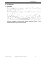
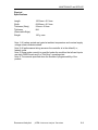
1.1 Overview
This manual describes the Rosemount Analytical Micro Continuous Emission
Monitoring (µCEM) gas Analyzer Module.
The µCEM Analyzer Module is designed to continuously determine the concentration of
O2, CO, SO2, and NOx in a flowing gaseous mixture. The concentration is expressed
in percent or parts-per-million.
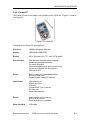
The sampled gas is collected from the stack and prepared by the Probe/Sample
Handling Enclosure for analysis and processing by the Analysis Enclosure. The
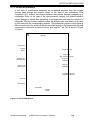
ANALYSIS ENCLOSURE is a stand alone, computer-controlled unit, utilizing PC/104
as the system bus. The uCEM is enclosed in rugged NEMA 4X, IP65 type enclosures,
for harsh environment. The ANALYSIS ENCLOSURE utilizes convection cooling with
no air intake and air vents. The ANALYSIS ENCLOSURE is modular, general purpose
and easily expandable. It utilizes industry standard components such as PC/104
boards, and modular signal conditioning modules.
Rosemount Analytical
µCEM Continuous Analyzer Transmitter
1–1
INTRODUCTION
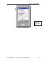
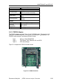
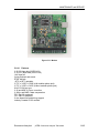
Figure 1-1. µCEM Micro Continuous Emission Monitoring – Analysis Enclosure
Rosemount Analytical
µCEM Continuous Analyzer Transmitter
1–2
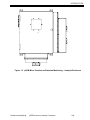
INTRODUCTION
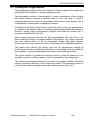
Figure 1-2. µCEM Micro Continuous Emission Monitoring Gas Analyzer with Time
Share option.
1.2 Time Shared Option
Provides the functionality to monitor and process sample gases from two streams on a
time-share scheme. This option allows you to connect one uCEM to two Sample
Handling units.
Rosemount Analytical
µCEM Continuous Analyzer Transmitter
1–3
INTRODUCTION
TV1
FROM
uCEM CAL
TO uCEM
SAMPLE
TV2
TV3
TO SHU1
CAL GAS
TO SHU2
CAL GAS
TV4
FROM SHU1
SAMPLE
FROM SHU2
SAMPLE
EXHAUST
Figure 1-3. Time Share option Flow Diagram
Rosemount Analytical
µCEM Continuous Analyzer Transmitter
1–4
INTRODUCTION
1.3 Theory of Operation
1.3.1 NOx
The NOx analyzer continuously analyzes a flowing gas sample for NOx [nitric oxide
(NO) plus nitrogen dioxide (NO2)]. The sum of the concentrations is continuously
reported as NOx.
The µCEM NOx Analyzer Module uses the chemiluminecence method of detection.
This technology is based on NO’s reaction with ozone (O3) to produce NO2 and oxygen
(O2). Some of the NO2 molecules produced are in an electronically excited state (NO2*
where the * refers to the excitation). These revert to the ground state, with emission of
photons (essentially, red light). The reactions involved are:
NO2 + O3 → NO2* + O2
NO2* → NO2 + red light
The sample is continuously passed through a heated bed of vitreous carbon, in which
NO2 is reduced to NO. Any NO initially present in the sample passes through the
converter unchanged, and any NO2 is converted to an approximately equivalent (95%)
amount of NO.
The NO is quantitatively converted to NO2 by gas-phase oxidation with molecular
ozone produced within the analyzer from air supplied by an external source. During the
reaction, approximately 10% of the NO2 molecules are elevated to an electronically
excited state, followed by immediate decay to the non-excited state, accompanied by
emission of photons. These photons are detected by a photomultiplier tube which
produces an output proportional to the concentration of NOx in the sample.
To minimize system response time, an internal sample bypass feature provides highvelocity sample flow through the analyzer.
1.3.2 CO
The optical bench can selectively measure multiple components in a compact design by using a
unique dual optical bench design. Depending on the application, any two combinations of NDIR
channels can be combined on a single chopper motor/dual source assembly.
Other application-dependent options include a wide range of sample cell materials, optical filters and
solid state detectors. The NDIR Microflow detector consists of two chambers, measurement and
reference with an interconnected path in which an ultra low flow filament sensor is mounted. During
operation, a pulsating flow occurs between the two chambers which is dependent upon: sample gas
absorption, modulation by the chopper motor and the fill gas of the detector chambers. The gas
flow/sensor output is proportional to the measured gas concentration. The optical bench is further
enhanced by a novel “Look-through” detector technique. This design allows two detectors to be
arranged in series --- enabling two different components to be measured on a single optical bench.
The optical bench contains a unique eddy current drive chopper motor and source assembly. This
design incorporates on board “intelligence” to provide continuous “self test” diagnostics.
Rosemount Analytical
µCEM Continuous Analyzer Transmitter
1–5
INTRODUCTION
1.3.3 O2
Paramagnetic: The determination of oxygen is based on the measurement of the magnetic
susceptibility of the sample gas. Oxygen is strongly paramagnetic, while other common gases
are not. The detector used is compact, has fast response and a wide dynamic range. The long
life cell is corrosion resistant, heated and may be easily cleaned. It has rugged self-tensioning
suspension and is of welded Non-Glued construction.
Rosemount Analytical
µCEM Continuous Analyzer Transmitter
1–6
INTRODUCTION
1.3.4 SO2
The optical bench can selectively measure multiple components in a compact design by using a
unique dual optical bench design. Depending on the application, any two combinations of NDIR
channels can be combined on a single chopper motor/dual source assembly.
Other application-dependent options include a wide range of sample cell materials, optical filters
and solid state detectors. The NDIR Microflow detector consists of two chambers, measurement
and reference with an interconnected path in which an ultra low flow filament sensor is mounted
during operation, a pulsating flow occurs between the two chambers which is dependent upon:
sample gas absorption, modulation by the chopper motor and the fill gas of the detector
chambers. The gas flow/sensor output is proportional to the measured gas concentration. The
optical bench is further enhanced by a novel “Look-through” detector technique. This design
allows two detectors to be arranged in series --- enabling two different components to be
measured on a single optical bench. The optical bench contains a unique eddy current drive
chopper motor and source assembly. This design incorporates on board “intelligence” to provide
continuous “self test” diagnostics.
Rosemount Analytical
µCEM Continuous Analyzer Transmitter
1–7
Detector Methodologies
2. Detector Methodologies
The µCEM can employ up to three different measuring methods depending on the
configuration chosen. The methods are: NDIR CO/SO2, Paramagnetic O2,
Electrochemical O2, and chemiluminescent NOx.
2.1 Non-Dispersive Infrared (NDIR)
The non-dispersive infrared method is based on the principle of absorption of infrared
radiation by the sample gas being measured. The gas-specific wavelengths of the
absorption bands characterize the type of gas while the strength of the absorption gives
a measure of the concentration of the gas component being measured.
An optical bench is employed comprising an infrared light source, two analysis cells
(reference and measurement), a chopper wheel to alternate the radiation intensity
between the reference and measurement side, and a photometer detector. The
detector signal thus alternates between concentration dependent and concentration
independent values. The difference between the two is a reliable measure of the
concentration of the absorbing gas component.
Depending on the gas being measured and its concentration, one of two different
measuring methods may be used as follows:
2.1.1 Interference Filter Correlation Method
With the IFC method the analysis cell is alternately illuminated with filtered infrared
concentrated in one of two spectrally separated wavelength ranges. One of these two
wavelength bands is chosen to coincide with an absorption band of the sample gas and
the other is chosen such that none of the gas constituents expected to be encountered
in practice absorbs anywhere within the band.
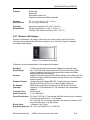
The spectral transmittance curves of the interference filters used in the µCEM analyzer
and the spectral absorption of the gases CO and CO2 are shown in Figure 2-1 below. It
can be seen that the absorption bands of these gases each coincide with the
passbands of one of the interference filters. The forth interference filter, used for
generating a reference signal, has its passband in a spectral region where none of
these gases absorb. Most of the other gases of interest also do not absorb within the
passband of this reference filter.
The signal generation is accomplished with a pyroelectrical (solid-state) detector. The
detector records the incoming infrared radiation. This radiation is reduced by the
absorption of the gas at the corresponding wavelengths. By comparing the
measurement and reference wavelength, an alternating voltage signal is produced.
This signal results from the cooling and heating of the pyroelectric detector material.
Rosemount Analytical
µCEM Continuous Analyzer Transmitter
2–1
DETECTOR METHODOLOGIES
Figure 2-1. Absorption Bands of Sample Gas and Transmittance of Interference Filters
2.1.2 Opto-Pneumatic Method
In the opto-pneumatic method, a thermal radiator generates the infrared radiation which
passes through the chopper wheel. This radiation alternately passes through the filter
cell and reaches the measuring and reference side of the analysis cell with equal
intensity. After passing another filter cell, the radiation reaches the pneumatic detector.
The pneumatic detector compares and evaluates the radiation from the measuring and
reference sides of the analysis cell and converts them into voltage signals proportional
to their respective intensity.
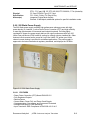
The pneumatic detector consists of a gas-filled absorption chamber and a
compensation chamber which are connected by a flow channel in which a Microflow
filament sensor is mounted. This is shown in Figure 2-2 below.
In principle the detector is filled with the infrared active gas to be measured and is only
sensitive to this distinct gas with its characteristic absorption spectrum. The absorption
chamber is sealed with a window which is transparent for infrared radiation. The
window is usually Calcium Fluoride (CaF2).
When the infrared radiation passes through the reference side of the analysis cell into
the detector, no pre-absorption occurs. Thus, the gas inside the absorption chamber is
heated, expands and some of it passes through the flow channel into the compensation
chamber.
Rosemount Analytical
µCEM Continuous Analyzer Transmitter
2–2
DETECTOR METHODOLOGIES
Absorption chamber
Flow channel with
Microflow sensor
CaF2 Window
Compensation chamber
Figure 2-2. Opto-Pneumatic Gas Detector
When the infrared radiation passes through the open measurement side of the analysis
cell into the detector, a part of it is absorbed depending on the gas concentration. The
gas in the absorption chamber is, therefore, heated less than in the case of radiation
coming from the reference side. Absorption chamber gas becomes cooler, gas
pressure in the absorption chamber is reduced and some gas from the compensation
chamber passes through the flow channel into the absorption chamber.
The flow channel geometry is designed in such a way that it hardly impedes the gas
flow by restriction. Due to the radiation of the chopper wheel, the different radiation
intensities lead to periodically repeated flow pulses within the detector.
The Microflow sensor evaluates these flow pulses and converts them into electrical
pulses which are processed into the corresponding analyzer output.
Rosemount Analytical
µCEM Continuous Analyzer Transmitter
2–3
DETECTOR METHODOLOGIES
2.1.3 Overall NDIR Method
In the case of dual-channel analyzers, the broadband emission from two infrared
sources pass through the chopper wheel. In the case of the Interference Filter
Correlation (IFC) method, the infrared radiation then passes through combinations of
interference filters. In the case of the opto-pneumatic method, the infrared radiation
passes through an optical filter depending on the application and need for reduction of
influences. Then the infrared radiation enters the analysis cells from which it is focused
by filter cells onto the corresponding detector. The preamplifier detector output signal is
then converted into the analytical results expressed directly in the appropriate physical
concentration units such as percent volume, ppm, mg/Nm3, etc. This is shown in Figure
2-3 below.
MOTOR
Light source
Chopper
blade
Duplex filter disc
Adapter cell
(high measuring range)
Analysis cell
measuring side
Analysis cell
(undivided)
Analysis cell
reference side
Preamplifier
Filter cell
Pyroelectric detector
(solid-state detector)
Filter cell
Gas detector
Preamplifier
Chopper
blade
Figure 2-3. Overall NDIR Method
Rosemount Analytical
µCEM Continuous Analyzer Transmitter
2–4
DETECTOR METHODOLOGIES
2.2 Paramagnetic Oxygen Method
The paramagnetic principle refers to the induction of a weak magnetic field, parallel and
proportional to the intensity of a stronger magnetizing field.
The paramagnetic method of determination of oxygen concentration utilizes nitrogen
filled quartz spheres arranged at opposite ends of a bar, the center of which is
suspended by and free to rotate on a thin platinum wire ribbon in a cell. Nitrogen (N2) is
used because it is diamagnetic or repelled by a magnet.
A small mirror that reflects a light beam coming from a light source to a photodetector,
is mounted on the platinum ribbon. A strong permanent magnet specifically shaped to
produce a strong, highly inhomogeneous magnetic field inside the analysis cell, is
mounted outside the wall of the cell.
When oxygen molecules enter the cell, their paramagnetism will cause them to be
drawn towards the region of greatest magnetic field strength. The oxygen molecules
thus exert different forces on the two suspended nitrogen filled quartz spheres,
producing a torque which causes the mirror to rotate away from its equilibrium position.
The rotated mirror deflects the incident light onto the photodetector creating an
electrical signal which is amplified and fed back to a coil attached to the bar holding the
quartz spheres, forcing the suspended spheres back to the equilibrium position.
The current required to generate the restoring torque to return the quartz bar to its
equilibrium position is a direct measure of the O2 concentration in the sample gas.
The complete paramagnetic analysis cell consists of an analysis chamber, permanent
magnet, processing electronics, and a temperature sensor. The temperature sensor is
used to control a heat exchanger to warm the measuring gas to about 55 °C.
Rosemount Analytical
µCEM Continuous Analyzer Transmitter
2–5
DETECTOR METHODOLOGIES
2.3 Electrochemical Oxygen Method
The electrochemical method of determining oxygen concentration is based on the
galvanic cell principle shown in Figure 2-4 below.
(Black)
Lead wire (Anode)
Lead wire (Cathode)
(Red)
Anode (1) (Lead)
O-Ring
Plastic disc (9)
Plastic top (10)
Resistor (6)
Thermistor (5)
Acid electrolyte (3)
Spong3 disc (7)
Cathode (2) (Gold film)
Teflon membrane (4)
Figure 2-4. Electrochemical Oxygen Sensor
The electrochemical oxygen sensor incorporates a lead and gold galvanic process with
a lead anode (1) and a gold cathode (2), using an acid electrolyte (3).
Oxygen molecules diffuse through a non-porous Teflon membrane (4) into the
electrochemical cell and are reduced at the gold cathode. Water is the byproduct of this
reaction.
On the anode, lead oxide is formed which is transferred into the electrolyte. The lead
anode is continuously regenerated and, therefore, the electrode potential remains
unchanged for a long time. The rate of diffusion and corresponding response time (t90)
of the sensor is dependent on the thickness of the Teflon membrane.
The electric current between the electrodes is proportional to the O2 concentration in
the sample gas being measured. The resultant signal is measured as a voltage across
the resistor (6) and thermistor (5), the latter of which is used for temperature
compensation. A change in the output voltage (mV) represents oxygen concentration.
NOTE: The electrochemical O2 cell requires a minimum internal consumption of
oxygen. Sample gases with an oxygen concentration of less than 2% could result in a
reversible detuning of sensitivity and the output will become unstable. The
recommended practice is to purge the cell with conditioned ambient air between
periods of measurement. If the oxygen concentration is below 2% for several hours or
days, the cell must be regenerated for about one day with ambient air. Temporary
flushing with nitrogen (N2) for less than one hour (analyzer zeroing) will have no effect
on the sensitivity or stability.
Rosemount Analytical
µCEM Continuous Analyzer Transmitter
2–6
DETECTOR METHODOLOGIES
(Red)
V out
Thermistor (5)
(Black)
Resistor (6)
(-)
(+)
Gold
Lead
Cathode (2)
Anode (1)
O2 + 4 H + 4 e → 2 H2O
2 Pb + 2 H2O → 2PbO + 4 H + 4 e
Electrolyte (3)
(ph 6)
Summary reaction O2 + 2 Pb → 2 PbO
Figure 2-5 Reaction of Galvanic Cell
Rosemount Analytical
µCEM Continuous Analyzer Transmitter
2–7
INSTALLATION
3. Installation
WARNING: ELECTRICAL SHOCK HAZARD
Installation and servicing of this device requires access to components
which may present electrical shock and/or mechanical hazards. Refer installation
and servicing to qualified service personnel.
CAUTION: CODE COMPLIANCE
Installation of this device must be made in accordance with all
applicable national and/or local codes. See specific references on installation
drawing located in the rear of this manual.
3.1 Specifications
Electrical Power
See Specifications in Preface
Power Cable
AC Operation: 16 gauge, minimum.
Gas Lines
For external gas lines, the use of all new tubing throughout is strongly recommended.
The preferred type is new, Teflon or Stainless Steel tubing, sealed at the ends.
Services
AC as well as input and output digital and analog signals connect through the circular
connectors located on the bottom of the uCEM enclosures.
Rosemount Analytical
µCEM Continuous Analyzer Transmitter
3–1
INSTALLATION
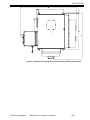
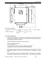
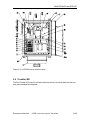
Figure 3-1. Dimensional Drawing, Door closed. Shown with Time Share option.
Rosemount Analytical
µCEM Continuous Analyzer Transmitter
3–2
INSTALLATION
O2 IN
O2 IN
CAL GAS
IN (CUST)
INST
AIR
BY
CUST
{
ATMOS
PRES
DRAIN
TO SAFE
PLACE
ELECTRICAL
CONNECTIONS
CAL GAS
OUT
O2 IN
INST
AIR
BY
CUST
{
ATMOS
PRES
DRAIN
TO SAFE
PLACE
Rosemount Analytical
ELECTRICAL
CONNECTIONS
µCEM Continuous Analyzer Transmitter
3–3
INSTALLATION
4" 150 LB
ASA RF
FLANGE
CONNECTION
3
REMOTE
OPERATION
FROM MCEM
CONTROLLER
SV1
STACK LOCATION
PI1
10
4
10
2
10
ADJUST FOR 10
20-30 PSIG
FI1
10
ANALYZER LOCATION
1/4SSBH/
3/8SSR
PR1
1
DE-ENERGIZED=STREAM 1
ENERGIZED=STREAM 2
INSTRUMENT AIR
60-125 PSIG
-40°F DEW POINT
1-5 SCFM
1/2 NPT MALE
10
SLOPE
7
BLOW
BACK
SAMPLE
1/4SSBH/
3/8SSR
ADJUST FOR
3-4 L/MIN
D
A
7
SP1
10
EOV1
C
3
10
10
B
CAL GAS
IN
1-2 LITER/MIN
CALIB
SET FOR
8-12 PSIG
RV1
11
6
SAMPLE FLOW
6
F2
SLOPE
11
TI1
10
IN
10
MS1
10
NO
C
SV1
SHU 1 CAL GAS
SAMPLE/CAL
TO ANALYZER
1-2 LITER/MIN
10
RC1B
NC
SHU 2 CAL GAS
DRAIN
EC1
PPD1
OUT
RC1A
uCEM CAL
2
10
IN
OUT
uCEM SAMPLE
1/4SSBH/
3/8SSR
10
NO
DRAIN
C
SV2
SHU 1 SAMPLE
14
14
NC
uCEM
CONTROL UNIT
SHU 2 SAMPLE
14
5
1/4SSBH/
3/8SSR
10
6
STREAM 1
SHU
ATMOS PRESSURE
DRAIN TO SAFE
LOCATION
4" 150 LB
ASA RF
FLANGE
CONNECTION
3
CAL
1/4 SSBH
SAMPLE
SSU
1/4 SSBH
+24VDC
3A
PI1
4
10
2
ADJUST FOR
20-30 PSIG
FI1
10
10
SLOPE
BLOW
BACK
D
BPR
SAMPLE
EOV1
ADJUST FOR
3-4 L/MIN
C
B
E
6
11
6
10
IN
F2
10
PPD1
OUT
DRAIN
MS1
10
PRS2
PRS1
CYL2
CYL1
J7
X PPM NO
IN NITROGEN
SPAN GAS
8-12 PSIG
SAMPLE/CAL
TO ANALYZER
1-2 LITER/MIN
10
RC1B
EXHAUST
EXHAUST
2
10
IN
OUT
RC1A
EC1
OZONE
OZONE
GENERATOR
1/4 SSBH
1/4SSBH/
3/8SSR
10
SLOPE
TI1
SET FOR
5 PSIG
F
CAL GAS
IN
1-2 LITER/MIN
SET FOR
8-12 PSIG
RV1
REACTION
CHAMBER
SAMPLE
SV1
1/4 SSBH
3
10
10
CALIB
11
SAMPLE FLOW
NOX TO NO
CONVERTER
SV2
ZERO
INSTRUMENT AIR
60-125 PSIG
-40°F DEW POINT
1-5 SCFM
DETECTOR
ASSY
PI
LOW
1/4SSBH/
3/8SSR
10
D
A
7
OPTIONAL
NDIR
DETECTOR
SV3
1/4 SSBH
G
10
7
NC
MANIFOLD
HIGH
1/2 NPT MALE
SP1
EO2
DETECTOR
C
C
1/4" O.D. X .035
WALL TUBING
(BY CUSTOMER)
1/4SSBH/
3/8SSR
PR1
PRESSURE
SWITCH
FI
SV4
1/4 SSBH
10
1
SET FOR
1.0 LPM ±0.5 LPM
A
ENCLOSURE
HAMMOND
P/N PJ1086L
REMOTE
OPERATION
FROM MCEM
CONTROLLER
B
SV3
NO
1
10
C
NC
EXHAUST
ATMOS PRESSURE
DRAIN TO SAFE
LOCATION
SV1
1/4 SSBH
NO
1/4SSBH/
3/8SSR
CAPILLARY
1
PI1
J6
SPU
PR1
OZ AIR
20.9% O2
IN NITROGEN
ZERO GAS
8-12 PSIG
SET FOR
12 PSIG
BY CUSTOMER
DRAIN
14
14
14
SHU
5
1/4SSBH/
3/8SSR
10
ATMOS PRESSURE
DRAIN TO SAFE
LOCATION
6
1/4" SS BULKHEAD
1/4SSBH/
3/8SSR
STREAM 2
ATMOS PRESSURE
DRAIN TO SAFE
LOCATION
Figure System Flow Diagram
53-030-06
1/4 VITON TUBING
59
31270
BULKHEAD PLATE
FRICTION
3W16W-1NR-V2A6
77 3 WAY VALVE
008436
1/8NPT-1/8t
904958
10-32w/seal - 1/8 t (barb)
CYL
IN
OUT
A6
SV4
100-900-472-04
MANIFOLD AND
2W1.3W-5DR-E2.46
2
WAY VALVES
76
SWAGELOC
SS-ORM2
TRIM VALVE
1/8NPT-1/8t
75
A12
IN
901090
816533
1/8FPT-1/8t
SAMPLE
42715604
NDIR DETECTOR
96
DWYER
RMA-14SSV
FLOW METER
& VALVE
FLOW
108
FRICTION
FRICTION I/8 TUBE
INSIDE 1/4 TUBE
78
816553
1/8FPT-1/8t
638614
GAUGE
31412
1/4 VITON
TUBING
93
CABLE
A15
029753
"T" CRES
901090
72
810156
1/8MPT-1/8t"T"
CAL
9032-904
95
A34
91
128
901090
656250
632784
FRICTION
904958
10-32w/seal - 1/8 t (barb)
CAL GAS 1
SV1
901090
904958
10-32w/seal - 1/8 t (barb)
CAL GAS 2
901090
A11
904958
10-32w/seal - 1/8 t (barb)
CAL GAS 3
632784
FRICTION
008436
1/8NPT-1/8t
SV2
029753
"T" CRES
905876
1/8MPT
-1/8t"T"
016429
A8
73
SV3
128
83
029650 1/4 X 1/8 BRASS
OZONE
AIR
82
016432
112
10-32 SET
SCREW
CRES
10-32 SET
SCREW
CRES
904017
REGULATOR
657719
EXHAUST
903348
98
31414
A13
005088
PLUG
1/4 X 1/4 BULKHEAD
90003311
PARAMAGNETIC
DETECTOR
902899 (4)
M4 X 16 SCREW
634398
903205
903205
99
079112
658157
RESTRICTOR
BRASS
31414
A7
812922
904956
812902
REDUCER
1/4 TUBING
(634398)
100
905277
1/4t "X"
31415
NOTES:
1. ALL TUBING 31413 1/8 DIA. NATURAL
UNLESS OTHERWISE INDICATED.
1/4 TUBING
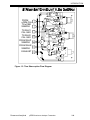
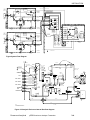
Figure 3-3 Analysis Enclosure Internal Gas flow diagram
Rosemount Analytical
µCEM Continuous Analyzer Transmitter
812922
3–4
659754
PHOTO DIODE
DETECTOR
INSTALLATION
Analysis Enclosure Critical settings and control:
1. Set MicroCEM Pressure guage (P1)to 5 psig +/- 0.5psig. Pressure set by BPR located behind
gauge in detector section. If CO and NOx response times are sluggish this pressure can be
increased.
2. Set Calibration gas cylinder dual stage pressure regulators to 10 to 20 psig.
3. Set Flowmeter (F1) to 500cc to 1500cc per min.
4. TV1 is used to balance the flow between a probe and local calibration. It is located beside the
solenoid valve manifold.
5. Set Ozone air pressure to 12 psig.
6. Exhaust line should be free of any backpressure. Immediately vent into ½” pipe.
7. Time Share Box:
TV1: Use to equalize cal gas flow between SHU1 and SHU2.
TV2: Use to equalize cal gas flow between SHU1 and SHU2.
TV3: Use to equalize sample flow between SHU1 and SHU2.
TV4: Use to equalize sample flow between SHU1 and SHU2.
8. Pressure Switch: The pressure switch is located beside the pressure gauge. If the sample or
cal gas pressure flow below 2.5 psig the MicroCEM will give trouble alarm. The alarm will turn
off upon pressure above 4 psig.
3.2 Process and Calibration Gas Connection
Besides sample gas, the µCEM requires other gases for operation. In most cases, one
or more Calibration Standards must be provided. These should be cylinders of gas
which closely resemble the expected sample, both in species and concentrations.
These calibration gases are normally introduced into the system as an input to the
Sample Conditioning Plate Option or sample conditioning may be provided by others.
Each gas cylinder should be equipped with a clean, hydrocarbon free two-stage
regulator with indicating gauges of approximately 0 to 3000 psig (0 to 20.7 Mpa) for
cylinder pressure and 0 to 100 psig (0 to 689 Kpa) for delivery pressure. Regulators
should have a metallic as opposed to elastomeric diaphragm, and provide for ¼ inch
compression fitting outlet and should be LOX clean.
NOTE: All connections specified in the Installation Drawing, in conjunction with
the Application Data Sheet, should be made.
Rosemount Analytical
µCEM Continuous Analyzer Transmitter
3–5
INSTALLATION
Figure 3-5. Gas Connections
1 – Sample Gas Inlet (From
Probe)
2 – Calibration Gas
(From Probe)
3 – Gas 3 Inlet (Cal
Gas)
5 – Gas 1 Inlet (Cal Gas)
6 – Ozone/Air Inlet
(By Cust)
7 – Vent (To Cust
vent)
4 – Gas 2 Inlet (Cal Gas)
3.2.1 Gas Conditioning
All gases must be supplied to the analyzer as conditioned gases! When the system is
used with corrosive gases, it must be verified that there are no gas components which
may damage the gas path components.
The gas conditioning must meet the following conditions:
Free of condensable constituents
Free of dust above 2 µm
Free of aggressive constituents which may damage the gas paths
Temperature and pressure in accordance with the specifications
When analyzing vapors, the dewpoint of the sample gas must be at least 10 °C below
the ambient temperature in order to avoid the precipitation of condensate in the gas
paths.
An optional barometric pressure compensation feature can be supplied for the µCEM.
This requires a pressure sensor with a range of 800 – 1,100 hPa. The concentration
Rosemount Analytical
µCEM Continuous Analyzer Transmitter
3–6
INSTALLATION
values computer by the detectors will then be corrected to eliminate erroneous
measurements due to changes in barometric pressure.
The gas flow rate must be in the range of 0.5 l/min to a maximum of 1.5 l/min. A
constant flow rate of 1 l/min is recommended. NOTE: The maximum gas flow rate for
paramagnetic oxygen detectors is 1.0 l/min!
Rosemount Analytical
µCEM Continuous Analyzer Transmitter
3–7
INSTALLATION
3.3 Installation
WARNING: ELECTRICAL SHOCK HAZARD
Care should be taken if hazardous gases are to be measured or used for
calibration.
Refer to installation drawing supplied with the application data package.
3.3.1 Location
The µCEM is designed to be installed in an outdoor environmental location. It is highly
recommended that the analyzer be located out of direct sunlight and direct rain/snow to
the extent possible to assure longevity and accuracies.
The µCEM analysis enclosure should be installed as near as possible to the
probe/sample handling enclosure, in order to avoid low response time caused by long
sample gas lines.
The enclosure must be grounded to earth by the user or ground loops and computer
lockups are possible.
3.3.2 Limitations
Ambient Temperature:
-30° to 50° Celsius (-34° to 122° F)
Relative Humidity:
5% to 99%
3.3.3 Mounting Options
Although the µCEM is enclosed in an environmentally sealed enclosure, it should be
protected from direct sunlight. In areas subjected to harsh winter climates, protection
should be provided from sun, rain and snow. A corrigated awning or other suitable
means can be provided to meet these conditions.
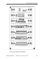
3.3.4 Electrical Connections
NOTE: The enclosure is a NEMA 4x. All entry locations must be sealed.
Connect all required signal cables to the connections at the bottom of the µCEM. The
cable locations are indicated on the inside bottom cover of the µCEM box. The actual
electrical connections will be specified in the Application Data package. All connections
are not necessary for every application.
Cable length for these signals should not exceed 3,000 feet (914 meters), to avoid
excessive capacitance and corresponding signal distortion.
All connections are made through the bottom of the µCEM enclosure using circular
connectors. Mating circular external connectors are provided by Rosemount with a 6’
wire harness pigtail for connections to J1, J3, J5, J6, J7 & J8.
Rosemount Analytical
µCEM Continuous Analyzer Transmitter
3–1
INSTALLATION
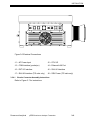
J8
SSU
J7
SHU 2
J6
SHU 1
J5
EXT I/O
J4
LAN
J3
COM
J2
CPU I/O
J1
AC POWER
INPUT
Figure 3-6 Electrical Connections
J1 – AC Power Input
J2 – CPU I/O
J3 – COM Interface (pocket pc)
J4 – Ethernet LAN Port
J5 – EXT I/O Interface
J6 – SHU #1 Interface
J7 – SHU #2 Interface (T/S units only)
J8 – SSU Power (T/S units only)
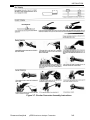
3.3.4.1 Circular Connector Assembly Instructions
Refer to Figure 3-7 for instructions.
Rosemount Analytical
µCEM Continuous Analyzer Transmitter
3–2
INSTALLATION
Figure 3-7. Circular Connector Assembly Instructions
Rosemount Analytical
µCEM Continuous Analyzer Transmitter
3–3
INSTALLATION
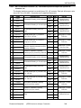
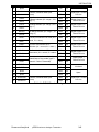
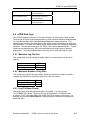
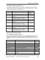
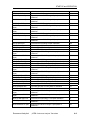
3.3.4.2 EXT I/O Interface Connector (J5) - MicroCEM inputs and outputs are specific for
customer use.
The Analog Interface connector has a shell size of 22, 100 contacts. Each pin will accept a wire
size of 26, 24, or 22 AWG. Connector and 6’ pigtail by Rosemount.
Pin#
NAME
1
O2CL+
2
O2CL-
3
COCL+
4
COCL-
5
NOxCL+
6
NOxCL-
7
EXP1CL+
8
EXP1CL-
9
EXP2CL+
10
EXP2CL-
11
12
13
14
NOTES
WHT
22
BLK
22
Analog Output /
Twisted Pair wire
WHT
22
BRN
22
NOx Stream#1 Reading, 4-20 mA
Output
WHT
22
RED
22
External process (No. 1), Customer
Analog input, 4-20 mA
WHT
22
ORG
22
WHT
22
YEL
22
WHT
22
GRN
22
WHT
22
BLU
22
WHT
22
VIO
22
WHT
22
GRY
22
BLK
22
BRN
22
BLK
22
RED
22
BLK
22
ORG
22
BLK
22
YEL
22
BLK
22
GRN
22
BLK
22
O2 Stream#1 Reading, 4-20 mA Output
CO Stream#1 Reading, 4-20 mA Output
External process (No. 2), Customer
analog input, 4-20 mA
PROCON1
Process On, Stream#1, Optically
PROCON1RTN Isolated Input (Dry contact by customer)
16
O2CL2-
17
O2 Stream#2 Reading, 4-20 mA Output
CO Stream#2 Reading, 4-20 mA Output
18
COCL2-
19
NOxCL2+
20
NOxCL2-
21
EXP3CL+
22
EXP3CL-
23
EXP4CL+
24
EXP4CL-
25
FLAME2
28
AWG
Flame Detect OR Initiate calibration,
Stream#1, Optically Isolated Input (Dry
FLAME1RTN contact by customer)
O2CL2+
27
COLOR
FLAME1
15
26
DESCRIPTION
NOx Stream#2 Reading, 4-20 mA
Output
External process (No. 3), Current Loop
input, 4-20 mA
External process (No. 4), Current Loop
input, 4-20 mA
Flame Detect, Stream#2, Optically
FLAME2RTN Isolated Input (Wet contact)
PROCON2
Process On, Stream#2, Optically
PROCON2RTN Isolated Input (Wet contact)
Trouble Indicator, Dry contact, 110V 1A
Rating
29
TRBLNO
30
TRBLC
BLU
22
31
TRBLNC
BLK
22
Rosemount Analytical
µCEM Continuous Analyzer Transmitter
Analog Output /
Twisted Pair wire
Analog Output /
Twisted Pair wire
Analog Input / Twisted
Pair wire
Analog Input / Twisted
Pair wire
Digital Input / Twisted
Pair wire (Cust
Digital Input / Twisted
Pair wire
Analog Output /
Twisted Pair wire
Analog Output /
Twisted Pair wire
Analog Output /
Twisted Pair wire
Analog Input / Twisted
Pair wire
Analog Input / Twisted
Pair wire
Digital Input / Twisted
Pair wire
Digital Input / Twisted
Pair wire
Digital Output /
Twisted Pair wire
3–4
INSTALLATION
94
Spare
VIO
22
32
Shutdown1+
BLK
22
33
Shutdown1-
GRY
22
34
O2LR+
O2 Range indicator (0V =range 1, 5V =
range 2 )
BRN
22
35
O2LR-
RED
22
36
COLR+
CO Range indicator (0V =range 1, 5V =
range 2 )
BRN
22
37
COLR-
ORG
22
38
NOxLR+
NOx Range indicator (0V =range 1, 5V
= range 2 )
BRN
22
39
NOxLR-
YEL
22
40
O2OL+
O2 Over Limit Indicator OR Valid (0V =
normal, 5V = alarm )
BRN
22
41
O2OL-
GRN
22
42
COOL+
CO Over Limit Indicator OR In
Calibration (0V = normal, 5V = alarm )
BRN
22
43
COOL-
BLU
22
44
NOxOL+
NOx Over Limit Indicator OR In
Maintenance (0V = normal, 5V = alarm
)
BRN
22
45
NOxOL-
VIO
22
46
STNNO
Stream Number Indicator, Optically
Isolated Output, Drty contact (open =
Stream#1 / closed = Stream#2)
BRN
22
47
STNC
GRY
22
74
BAROP+
RED
22
75
BAROP-
YEL
22
98
Spare
RED
22
100
Spare
ORG
22
72
Shutdown2+
RED
22
73
Shutdown2-
GRN
22
ShutDown, Stream#1 Mode (Wet
contact)
ShutDown, Stream#2 Mode (Wet
contact)
Digital Input / Twisted
Pair wire
Digital Output TTL /
Twisted Pair wire
Digital Output TTL /
Twisted Pair wire
Digital Output TTL /
Twisted Pair wire
Digital Output TTL /
Twisted Pair wire
Digital Output TTL /
Twisted Pair wire
Digital Output TTL /
Twisted Pair wire
Digital Output /
Twisted Pair wire
Not Used
Spare
Digital Input / Twisted
Pair wire
Table 3-1. EXT I/O Terminal Assignments
Rosemount Analytical
µCEM Continuous Analyzer Transmitter
3–5
INSTALLATION
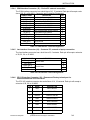
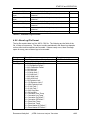
3.3.4.3 SHU #1 / #2 Interface Connector (J6 & J7). These wires are to be connected directly to
the MicroCEM sample handling enclosure (SHU) and will control the operation of the
sample pump, drain pump, purge valve and calibration valve respetively. All toggle
switches in sample handling enclosure should be set to “remote” mode upon hookup of wire
so the MicroCEM analysis enclosure will control the full system.
The Digital Interface connector has a shell size of 14, 15 contacts. Each pin will accept a wire
size of 20 AWG. Connector and 6’ pigtail by Rosemount.
PIN
NAME
1
SPUMP1/2NO
DESCRIPTION
Sample Pump #1/2 Control,
Dry contact, 110V 1A
COLOR
Sample Handling
Enc. Termination
BLK
Not Used
BRN
1
2
SPUMP1/2C
3
SPUMP1/2NC
RED
8
4
DPUMP1/2NO
ORG
Not Used
5
DPUMP1/2C
YEL
1
6
DPUMP1/2NC
GRN
3
7
PURG1/2NO
BLU
4
8
PURG1/2C
VIO
1
9
PURG1/2NC
GRY
Not Used
10
CAL1/2NO
WHT
5
11
CAL1/2C
12
CAL1/2NC
Drain Pump #1/2 Control,
Dry contact, 110V 1A
Purge Valve #1/2 Control,
Dry contact, 110V 1A
Calibration Valve #1/2
Control,
Dry contact,
110V 1A
WHT/BLK 1
WHT/BRN Not Used
Internal Jumper terminals 2 and 9 set by Rosemount
Table 3-2. Sample Handling Unit Terminal Assignments
Rosemount Analytical
µCEM Continuous Analyzer Transmitter
3–6
INSTALLATION
3.3.4.4 COM Interface Connector (J3) – Pocket PC external connection
The COM Interface connector has a shell size of 10, 13 contacts. Each pin will accept a wire
size of 28, 26, or 24 AWG. Connector and 3’ pigtail by Rosemount.
SIGNAL NAME
DCD (pin 1)
DSR (pin 6)
RxD (pin 2)
RTS (pin 7)
TxD (pin 3)
CTS (pin 8)
DTR (pin 4)
RI (pin 9)
GND (pin 5)
DEFINITION
Data Carrier Detect Input, RS232
Data Set Ready Input, RS232
Receive Data Input, RS232
Request to Send Output, RS232
Transmit Data Output, RS232
Clear To Send Input, RS232
Data Terminal Ready Output, RS232
Ring Indicator Input, RS232
Signal Ground, RS232
TxD/RxD+ (pin 2) RS-485 Bidirectional Data
TxD/RxD- (pin 7) RS-485 Bidirectional Data
GND (pin 3)
VCC
PIN
1
2
3
4
5
6
7
8
9
10
11
Signal Ground
12
+5V DC
13
Table 3-3. COM Interface Terminal Assignments
3.3.4.5 Lan Interface Connector (J4) – Customer PC, network or laptop connection
The Lan Interface connector has a shell size of 8, 6 contacts. Each pin will accept a wire size
of 28, 26, 24, or 22 AWG.
SIGNAL NAME
TxD+ (pin 1)
TxD- (pin 2)
RxD+ (pin 3)
RxD- (Pin 6)
DEFINITION
Transmit Data
Receive Data
Not Used
PIN
1
2
3
4
5-6
Table 3-4. LAN Interface Terminal Assignments
3.3.4.6 CPU I/O Interface Connector (J2) – Rosemount Factory trained port for
communication with CPU hard drive
The CPU I/O Interface connector has a shell size of 14, 19 contacts. Each pin will accept a
wire size of 28, 26, or 24 AWG.
Rosemount Analytical
PIN
NAME
DESCRIPTION
A
RED
RED CENTER
B
GND
RED SHIELD
C
GREEN
GREEN CENTER
D
GND
GREEN SHIELD
E
BLUE
BLUE CENTER
F
GND
BLUE SHIELD
G
HSYNC
GREY CENTER
H
GND
GREY SHIELD
µCEM Continuous Analyzer Transmitter
3–1
INSTALLATION
J
VSYNC
BLACK CENTER
K
GND
BLACK SHIELD
L
DATA
DCC DATA
M
CLK
DCC CLK
N
KBDATA
KEYBOARD DATA
P
KBCLK
KEYBOARD CLOCK
R
GND
GROUND
S
VCC
VCC, +5VDC
R
GND
GROUND
S
VCC
VCC, +5VDC
T
MSDATA
MOUSE DATA
U
MSCLK
MOUSE CLOCK
Table 3-5. CPU I/O Terminal Assignments
3.3.4.7 SSU Power Connector, T/S units Only (J8) – T/S enclosure can be located away from
the Analysis enclosure. This cable serves as the connection and is by Rosemount.
The SSU Power connector has a shell size of 8, 3 contacts. Each pin will accept a wire size of
24, 22, or 20 AWG. Connector and 6’ pigtail by Rosemount.
SIGNAL NAME
SSUCtrl
Vbb_rtn
Gnd
DEFINITION
SSU Control line
+24V Return
GND
PIN
A
B
C
Table 3-6. SSU Power Connection Terminal Assignments
3.3.4.8 AC Power Connector (J1) – Customer 120VAC Power Connection
The AC Power Interface connector has a shell size of 12, 3 contacts. Each pin will accept a
wire size of 16 AWG. Connector and 6’ pigtail by Rosemount.
SIGNAL NAME
L1
L2
GND
DEFINITION
85-264 VAC, 47-440 Hz
AC Ground
PIN
A
C
B
Table 3-7. AC Power Connection Terminal Assignments
Connect AC power through a 20A circuit breaker that is to be located close to the
µCEM. The circuit breaker will provide over current protection as well as a means of
disconnecting the power.
Maximum power requirements will be 1000 watts, with most applications requiring less
than this amount
Rosemount Analytical
µCEM Continuous Analyzer Transmitter
3–2
INSTALLATION
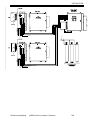
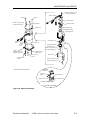
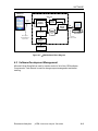
Figure 3-4. uCEM Analysis Enclosure interconnect diagram
Rosemount Analytical
µCEM Continuous Analyzer Transmitter
3–3
INSTALLATION
3.3.5 Analytical Leak Check
If explosive or hazardous gas samples are being measured with the µCEM, it is
recommended that gas line fittings and components be thoroughly leak-checked prior
to initial application of electrical power, and at bimonthly intervals thereafter, as well as
after any maintenance which involves breaking the integrity of the sample containment
system.
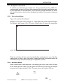
3.3.5.1 Flow Indicator Method
Figure 3-8. Leak Test Flow Method
Supply air or inert gas such as nitrogen, at 10 psig (689 hPa), to the analyzer through a
flow indicator with a range of 0 to 250 cc/min. Install a shut-off valve at the sample gas
outlet. Set the flow rate to 125 cc/min.
Close the outlet shut-off valve and notice that the flow reading drops to zero. If the flow
reading does not drop to zero, the system is leaking and must be corrected before the
introduction of any flammable sample gas or application of power.
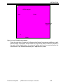
3.3.5.2 Manometer Method
Install a water-filled U-tube manometer at the sample gas outlet. Install a shut-off valve
at the sample gas inlet. Admit air or inert gas to the inlet shut-off valve until the analyzer
is pressurized to approximately 50 hPa. The water column will be about 500 mm.
N2
10 psig
(69 kPa)
Flow
Meter
Gas
Outlet
Rosemount Analytical
µCEM Continuous Analyzer Transmitter
3–1
INSTALLATION
UCEM Analyzer
Inlet
Outlet
Overpressure
approx. 50
N2
Water
Figure 3-9. Leak Test Manometer Method
Close the inlet shut-off valve and, following a brief period for pressure equilibrium, verify
that the height of the water column does not drop over a period of about 5 minutes. If
the water column height drops, the system is leaking and must be corrected before the
introduction of any flammable sample gas or application of power.
Rosemount Analytical
µCEM Continuous Analyzer Transmitter
3–2
INSTALLATION
3.3.5.3 Troubleshooting Leaks
Liberally cover all fittings, seals, and other possible sources of leakage with a suitable
leak test liquid such as SNOOP™ (part 837801). Bubbling or foaming indicates
leakage. Checking for bubbles will locate most leaks but could miss some, as some
areas are inaccessible to the application of SNOOP. For positive assurance that
system is leak free, perform one of the preceding tests.
NOTE:
Refer to Specification in Preface for maximum pressure limitations.
For differential measurement, the leak check must be performed for the
measurement and reference side separately.
For analyzers with parallel gas paths, the leak check must be performed
for each gas path separately.
Figure illustrates MicroCEM analysis enclosure (Left) wire connections to the Sample Handling box
™
Trademark of NUPRO Company
Rosemount Analytical
µCEM Continuous Analyzer Transmitter
3–3
INSTALLATION
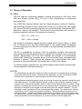
4. Startup and Operation
4.1 Startup Procedure
Once the µCEM has been correctly assembled and installed in accordance with the
instructions
in
Section
1.1,
“
Rosemount Analytical
µCEM Continuous Analyzer Transmitter
4–1
STARTUP and OPERATION
Installation,” the analyzer is ready for operation.
Before operating the system, verify that the Leak Checks have been
performed and that the sample handling unit is performing correctly.
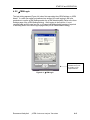
MicroCEM analysis enclosure On/Off switch is located inside the door on
the bottom right hand corner. Push switch to the “on” position to start
system.
The unit will immediately run thru a self diagnostic mode. This may take up
to 2 minutes. The user will know the system has passed all diagnostic test
and is “ready” upon the green LED (located above on/off switch) flashing. If
the green LED does not start to flash verify that proper power is connected
to the unit and restart. If AC/Heater fan is running but the green LED still
will not flash then call the factory immediately for help.
NOTE: After startup a warm-up time from 20 to 60 minutes (Depending
upon ambient temp) is required for accurate measuements.
Analyzer operation can be confirmed by the green LED light flashing. The
pocket pc can then be connected for viewing menus. Upon power up, the
analyzer will perform a self-test routine. The test will take approximately 6
minutes.
4.2 Analyzer Operation
4.2.1 User Interface
The µCEM User Interface runs on a Pocket-PC with Windows CE operating system. It
communicates with the µCEM via serial communication port. All input to the Pocket-PC
is done using a pointing device that comes with the Pocket-PC. The Pocket PC can be
plugged into two different ports. The first port is located on the front panel below the
on/off switch inside the front door. The second port is from the bottom of the uCEM via
J3 connector.
The pocket PC can be found behind the door behind the glass piece. Note that upon
shipment the pocket PC may be located in a separate box.
To connect the pocket PC to the: µCEM via the inside connection.
1. Open µCEM door.
2. Plug RS232 plug into adapter located on front panel
3. Plug power supply cable into 5V adapter
4. Turn Pocket PC on
5. In order to assure no other windows are open press the reset button. Reset
button is located on the back of the pocket PC.
6. Go to tools menu (Icon in upper left hand corner) and click on µCEMTS.
7. Unit will display data in 3 to 5 seconds. If unit does not show data in 3 to 5
seconds repeat procedure starting with number 5.
To connect the pocket PC to the: µCEM via the outside connection.
Rosemount Analytical
µCEM Continuous Analyzer Transmitter
4-1
STARTUP and OPERATION
1. Plug the external COM cable into J3 circular connector on the bottom of the
uCEM.
2. Plug pocket pc RS232 plug into the J1 on the external COM cable.
3. Plug power supply cable into 5V plug on the COM cable.
4. Turn Pocket PC on.
5. In order to assure no other windows are open press the reset button. Reset
button is located on the back of the pocket PC.
6. Go to tools menu (Icon in upper left hand corner) and click on µCEMTS.
7. Unit will display data in 3 to 5 seconds. If unit does not show data in 3 to 5
seconds repeat procedure starting with number 5.
Note: The Pocket PC can by used on any MicroCEM TS analysis enclosure regardless
of the MicroCEM units IP address.
4.2.2 µCEM Main Window
The µCEM Main Window shown in Figure 4-1 provides the status of the three emissions
channels. The status includes the current reading (updated approximately every 2
seconds), the last 1-minute average, and the last 15-minute average. The status column
(Sts) indicates the status of the measurement and can be any of the values in the Table
4-1.
Rosemount Analytical
µCEM Continuous Analyzer Transmitter
4-2
STARTUP and OPERATION
Table 4-1 - Status Values
Shown in
order of
precedence.
Maintenance
mode status
takes highest
precedence.
Status
Description
M
Indicates that maintenance mode is active.
C
Calibration in process
I
Invalid Reading. Indicates that the reading is
invalid due to calibration failure or Low Pressure
flow alarm.
V
Valid Reading
P
Customer Process Off Line (Dry contact by cust)
B
System is in By-Pass mode (Stream Switch)
O
µCEM System powered off
Drag the edges of
the columns to
resize the columns
Use the scrollbar
to see the full set
of data
Figure 4-1 - µCEM Main Display
Rosemount Analytical
µCEM Continuous Analyzer Transmitter
4-3
STARTUP and OPERATION
4.2.3 µCEM Menus
Lower left part of the µCEM screen contains three menus, from which all of the µCEM
user-interface functions can be accessed. There are three main menus: File, Tools and
Advanced, presented on Figures 4-2.1, 4-2.2, and 4-2.3.
File Menu: Provides General access to Connect, Log-in, Log Off features
Tools Menu: Provides access to basic µCEM Tools, like alarms and stream switching
Advanced Menu: Provides access to advanced µCEM Features, like Stream Settings
and User Administration
Toolbar Buttons: Shortcuts to Alarms, µCEM Settings, µCEM Admin, Stream Switching
Toolbar Buttons: Shortcuts
to Alarms, µCEM
Settings, µCEM Admin.,
Data Logs and About
Tools Menu: Provides
access to all
functionality
Note: Exit will only be
available when
current user has
administrative
access
Rosemount Analytical
Figure 4-2.1 - µCEM File Menu
µCEM Continuous Analyzer Transmitter
4-4
STARTUP and OPERATION
Figure 4-2.2 - µCEM Tools Menu
Figure 4-2.3 - µCEM Advanced Menu
Rosemount Analytical
µCEM Continuous Analyzer Transmitter
4-5
STARTUP and OPERATION
4.2.4 µCEM Alarms
The µCEM Alarms dialog shows all the current alarms. A current alarm is one with an
Active status of 1 (active) or an Acknowledged state of 0 (not acknowledged).. To see
the historical Alarms for the last 3 months , the web based µCEM interface must be
used. If one or more alarms are current, the most recent of them will be displayed on
the main display. If more than one alarm is current “(more)” will be displayed after the
name of the most recent alarm on the main window to indicate that more than one alarm
is active. Horizontal scroll bar is be used to see Date and Time of the Alarms. Alarms
can be General and Stream-specific. By selecting the radio buttons on the bottom, user
can view different types of alarms.
Drag the edges of
the columns to
resize the columns
Use the scrollbar
to see the full set
of data
Figure 4-3. Pocket PC Alarms Screen
Alarms with a critical level will cause the System trouble output to become active when
the alarm is active. When all active critical alarms are acknowledged, the System
trouble output will become inactive.
Alarm Name
O2 Calibration
Failed
CO Calibration
Failed
NOx Calibration
Failed
Rosemount Analytical
Level
Critical
Critical
Critical
Description
O2 Calibration Failed to meet the
maximum Drift requirements
CO Calibration Failed to meet the
maximum Drift requirements
NOx Calibration Failed to meet the
maximum Drift requirements
µCEM Continuous Analyzer Transmitter
Type
Stream
Specific
Stream
Specific
Stream
Specific
4-6
STARTUP and OPERATION
O2 High Limit
Critical
O2 Low Limit
Critical
CO High Limit
Critical
CO Low Limit
Critical
NOx High Limit
Critical
Nox Low Limit
Critical
24V Over Max
Critical
24 Low Min
Critical
O2 Emission Limit
Warning
CO Emission Limit
Warning
NOx Emission Limit
Warning
Converter Over
Temp
Converter Low
Temp
Zone Over Temp
Critical
Zone Low Temp
Critical
PDT Over Temp
Critical
PDT Low Temp
Critical
PMT Over Temp
Critical
PMT Low Temp
Critical
Low Pressure
Critical
Warmup Time Limit
Critical
Critical
Critical
O2 Sensor reading is above the
minimal acceptable limit
O2 Sensor reading is below the
minimal acceptable limit
CO Sensor reading is above the
minimal acceptable limit
CO Sensor reading is below the
minimal acceptable limit
NOx Sensor reading is above the
minimal acceptable limit
NOx Sensor reading is below the
minimal acceptable limit
24V diagnostic input exceeds the
specified maximum
24V diagnostic input is below the
specified minimum
O2 reading is over the specified
Limit
CO reading is over the specified
Limit
NOX reading is over the specified
Limit
Converter temperature reading
exceeds the specified maximum
Converter temperature reading is
below the specified minimum
Zone temperature reading
exceeds the specified maximum
Zone temperature reading is below
the specified minimum
Peltier Cooler (PDT) temperature
reading exceeds the specified
maximum
Peltier Cooler (PDT) temperature
reading is below the specified
minimum
PDD Chamber temperature
reading exceeds the specified
maximum
PDD Chamber temperature
reading is below the specified
minimum
Low Sample Flow Pressure is
detected (Below 2.5psi)
System Warm-up process
exceeded the specified time limit
Stream
Specific
Stream
Specific
Stream
Specific
Stream
Specific
Stream
Specific
Stream
Specific
General
General
Stream
Specific
Stream
Specific
Stream
Specific
General
General
General
General
General
General
General
General
Stream
Specific
General
Table 4-2 – Alarm Summary
Rosemount Analytical
µCEM Continuous Analyzer Transmitter
4-7
STARTUP and OPERATION
4.2.5 µCEM Login
The login dialog appears (Figure 4-4) when first requesting the µCEM Settings or µCEM
Admin. If a valid user name and password are entered, the user logging in will have
permission to use the µCEM Settings and/or the µCEM Administration (Refer to the User
Settings page of the µCEM Settings dialog). After logging in the first time, it is not
required again until the user logs out, or is logged out automatically because of a period
of inactivity (Refer to the Auto Logout page of the µCEM Administration dialog).
On-screen keyboard is
available at any time
by clicking on the
keyboard button.
Figure 4-4 - µCEM Login
Rosemount Analytical
µCEM Continuous Analyzer Transmitter
4-8
STARTUP and OPERATION
4.2.6 µCEM Login-Current User Indication
When a user is logged in, the µCEM main display will indicate the user name of the
logged in user as shown in Figure 4-5.
Current user and
Log off button.
Figure 4-5 - Current User Indication
Rosemount Analytical
µCEM Continuous Analyzer Transmitter
4-9
STARTUP and OPERATION
4.2.7 Stream Switching Control
Typically a dual stream system is in Automatic Stream Switching mode. That means that
it runs the timing schedule specified in User Settings Configuration file. If Automatic
switching is not desirable, the user may turn it off using Tools-> Stop Auto Switching
menu. In this case the system will remain on the current stream indefinitely. When
Automatic switching is needed again, user may turn it back on with Tools->Start Auto
Switching menu.
The same task can be accomplished remotely, by clicking Stop Auto Switching button on
the µCEM Real-Time Web page.
Note, that this option is sustained even if the system is rebooted.
The operator may also force a switch between the streams at any time whether the
system is in Auto-Switching mode or not. Tools menu has an option “Switch to
StreamName”, where StreamName is a user-specified name of the stream.
The same task can be accomplished remotely by clicking Switch to “StreamName”
button on the µCEM Real-Time Web page.
Rosemount Analytical
µCEM Continuous Analyzer Transmitter
4-10
STARTUP and OPERATION
4.3 µCEM Settings
The µCEM Settings dialog is only available to users with µCEM Settings permission. If a
user is not currently logged in, the login dialog will be displayed. If the current user
doesn’t have µCEM Settings permission, µCEM will not allow Settings screen to appear.
When the µCEM Settings are invoked from the Advanced menu or the µCEM Settings
button, the µCEM Settings tabbed dialog is displayed. The Range page (tab) is
displayed initially.
4.3.1 µCEM Settings-Range
The Range Settings page is used to specify the range for the analog outputs. Setting
Range 2 to a value of 0 (zero) enables single range functionality and disables the
dual range function. For Dual Range applications do not set range 2 equal too or
higher than Range 1 or the system will not calibrate properly. Note that Range 1 can be
changed by the user but must be changed in the webrowser tools. See the Webrowser
user settings section.
The dual range setting will enable the analyzer software and diagnostics to perform two
separate performance curves for each range thus enhancing the measuring capabilities
of the analyzer. A dual range setting is desired for applications burning dual fuels or that
may display high dynamic reading between the low and high of the day. The analog
outputs will also support the dual range mode. When the emission is below the Range 2
value, the analog output will switch to Range 2 mode and the Range 2 value becomes
the full-scale value of the analog output. The range indication digital output will change
to the Range 2 state. When the emission is above the Range 2 value, the output
switches to Range 1 mode and the Range 1 value becomes the full-scale value of the
output. The range indication digital output will change to the Range 1 state.
Rosemount Analytical
µCEM Continuous Analyzer Transmitter
4-11
STARTUP and OPERATION
The Tabs allow
selection of the
µCEM Settings
pages.
Figure 4.6 - Range Settings
Rosemount Analytical
µCEM Continuous Analyzer Transmitter
4-12
STARTUP and OPERATION
4.3.2 µCEM Settings-Auto Calibration
The Auto-Calibration settings are set on the Auto-Calibration page of the µCEM settings.
If auto calibration is turned to the on position, then the user can select time and/or
frequency of the auto calibration in the Auto Calibration Frequency tab (4.3.3).
Note: Both manual and auto calibration need to be perform with the MicroCEM
enclosure door in the closed position. If the door is opened then critical detector
temperatures will vary which will cause a drift in the calibration. If the door is kept open
long enough for temps to be constant at their setpoints then an open door calibration is
acceptable. See section 4.7 “temp diagnostics”- for details on temperature setpoints.
Figure 4.7 - Auto Calibration Settings
Rosemount Analytical
µCEM Continuous Analyzer Transmitter
4-13
STARTUP and OPERATION
4.3.3 µCEM Settings - Auto Calibration Time and Frequency
The Auto-Calibration Time and Frequency tab allows specifying time and frequency of
the auto-calibration. Time field requires military time format. The times are displayed in
Military time type.
Figure 4.8 - Auto Calibration Time and Frequency
Rosemount Analytical
µCEM Continuous Analyzer Transmitter
4-14
STARTUP and OPERATION
4.3.4 µCEM Settings-Limits
The emission limits alarms can be set on the Limits page of the µCEM Settings. When a
measured emission exceeds its limit, the emission will have a limit-exceeded status.
This is indicated on the main display and on the Data-Logs display. It is also indicated in
the limit exceeded digital output.
Figure 4.11 - Limit Settings
Rosemount Analytical
µCEM Continuous Analyzer Transmitter
4-15
STARTUP and OPERATION
4.3.5 µCEM Settings-Calibration Gas
The Calibration Gas values and Gas Bottle allocation may be set on the Calibration Gas
page of the µCEM Settings. This should be set whenever a Calibration Gas container is
replaced or upon Startup of the system.
Calibration Gas Values:
R1Mid: This is typically used for CGA audits and not for daily calibrations. The specific
calibration gas mid value (typically between 40% to 60% of range) is set in this space.
The MicroCEM will perform mid calibration on Range 1 on this gas but will not perform
any corrections. This box should typically be left blank. It is mostly used as a check.
R1Span: The specific calibration gas span value (typically between 80% to 100% of
range) is set in this space for Range 1. A Nox range of 0-100ppm would typically use a
gas bottle with 90ppm NOx balance N2.
R2Mid: This is typically used for CGA audits and not for daily calibrations. The specific
calibration gas mid value (typically between 40% to 60% of range) is set in this space.
The MicroCEM will perform a mid calibration on Range 2 on this gas but will not perform
any corrections. This box should typically be left blank. It is mostly used as a check.
R2Span: The space is allocated for dual range applications. If the MicroCEM range
setting is set for single range then the user will not be able to input any value into this
space. The specific calibration gas span value (typically between 80% to 100% of
range) is set in this space. A Nox range of 0-10ppm would typically use a gas bottle with
9ppm NOx balance N2.
Note that zero values do not have to be input into this page. For all zero calibrations the
user must assure that the calibration gas used does not have any levels of the
measurement gas in the cylinder. For example upon the analyzer zeroing O2, the bottle
used must have 0% O2 in the Bottle. Zeroing the O2 is typically performed by using the
NOx or CO Span gases.
Gas Bottle Allocation:
Gas 1, Gas 2 and Gas 3 are labels for the respective location of where the calibration
gas cylinders are physically located on the external fittings.
Off: Designates that no operation will be performed.
Zero: The MicroCEM will perform a zero calibration.
R1Span: MicroCEM will perform a Span calibration for Range 1.
R2Span: MicroCEM will perform a Span calibration for Range 2. Note that if a second
range is NOT chosen in the range settings menu then user will not be able to input any
value into this space. Range 2 should always be a lower value than range 1 if used.
R1Mid: MicroCEM will perform a Mid Calibration for Range 1.
R2Mid: MicroCEM will perform a Mid Calibration for Range 2. Note that if a second
range is NOT chosen in the range settings menu then user will not be able to input any
value into this space.
Rosemount Analytical
µCEM Continuous Analyzer Transmitter
4-16
STARTUP and OPERATION
Figure 4.12 - Calibration Gas Settings
Rosemount Analytical
µCEM Continuous Analyzer Transmitter
4-17
STARTUP and OPERATION
4.3.6 µCEM Settings-Maintenance Mode
Maintenance mode may be selected for any of the emission types on the Maintenance
Mode page of the µCEM Settings.
Choosing maintenance mode will invoke an “M” flag” onto the data. Customer can
perform routine maintenance while in this setting
This mode is typically used when preventive maintenance is being performed. The M
flag signifies to the EPA that the values reported are not valid therefore should not be
applied to emissions reporting.
Upon completion of Maintenance the user must go back into this screen to turn the
Maintenance off. If not, the MicroCEM will continue to show the M flag in the data.
Figure 4.13 - Maintenance Mode Settings
Rosemount Analytical
µCEM Continuous Analyzer Transmitter
4-18
STARTUP and OPERATION
4.3.7 µCEM -Manual Calibration
A dry-run Calibration may be initiated from the Manual Calibration page of the µCEM
Settings by pressing the Manual Calibrate All icon. A full zero and span calibration will
be run by the MicroCEM but the end result corrections of the calibration will not be
applied to the O2/Nox/CO measurement values. If desired a partial calibration may be
invoked for one or more of the emission types. While the manual calibration is in
process, a calibration progress dialog will be displayed as shown in Figure 4.24. When
the manual calibration is completed, the results are displayed in the Manual Calibration
Results dialog as shown in Figure 4.10. If the Local Calibration checkbox is checked,
the Local Calibration valve will be used during the calibration rather than the probe
Calibration valve.
Note that “Start Auto Cal now” will invoke a calibration and will apply new correction
factor to all measurement when done.
Figure 4.9 - Manual Calibration Menu
Rosemount Analytical
µCEM Continuous Analyzer Transmitter
4-19
STARTUP and OPERATION
4.3.8 Auto Calibration
The Auto Calibration dialog is displayed whenever calibration is in process. It displays
the current emission values and the status of the calibration. The calibration may be
canceled before it completes by pressing the Cancel button.
Note: The title of this dialog will
read either “Auto Calibration” or
“Manual Calibration” to indicate
how the calibration process was
initiated.
Figure 4.22 - Auto Calibration Status Screen
Use the scrollbar
to see the full set
of results
Figure 4.10 - Manual Calibration Results
Rosemount Analytical
µCEM Continuous Analyzer Transmitter
4-1
STARTUP and OPERATION
4.4 µCEM Administration
The µCEM Administration dialog is only available to users with µCEM Administration
permission. If a user is not currently logged in, the login dialog will be displayed. If the
current user doesn’t have µCEM Administration permission, a message will be displayed
which reads “Permission denied”. When the µCEM Administration is invoked from the
Tools menu or the µCEM Administration button, the µCEM Administration tabbed dialog
is displayed. The User Settings page (tab) is displayed initially.
4.4.1 µCEM Administration-User Settings
The user settings page of the µCEM Administration dialog allows users to be added,
deleted or modified. Each user has a name, password, and permission settings. The
permission settings include Settings permission that allows access to the µCEM Settings
dialog, and Administrative permission that allows access to the µCEM Administration
dialog. The Settings permission also allows a user to access the µCEM remotely using
the web-based interface.
Figure 4.14 - User Settings
Rosemount Analytical
µCEM Continuous Analyzer Transmitter
4-2
STARTUP and OPERATION
4.4.2 µCEM Administration-Auto Logoff
The number of minutes of inactivity after which a user is automatically logged off is set
on the Auto Logoff page of the µCEM Administration.
Figure 4.15 - Auto Logoff
Rosemount Analytical
µCEM Continuous Analyzer Transmitter
4-3
STARTUP and OPERATION
4.5 µCEM Factory and User Settings
A µCEM Factory and User Settings files are available for use by µCEM technicians to
set parameters in the µCEM or a qualified customer technician.
µCEM Settings are separated into two files: Factory Settings and User Settings. Factory
Settings should be modified by a Rosemount technician only. Note: Some parameters in
this file, if set incorrectly, may cause permanent damage to hardware.
User Settings can be modified by a qualified customer technician. User settings are
accessible through the User Settings Web screen. See section 4.7 for details on
access. Settings files are formatted as a standard Windows INI files. File is organized
in sections (in square brackets). Configuration Parameters are presented in “Name =
Value” format. Comments start with semicolon. User Settings files has three sections
[General], [Stream 1] and [Stream 2].
The list of some settings is shown in Table 4.3 & Table 4.4.
Consult a Rosemount factory person for details.
Rosemount Analytical
µCEM Continuous Analyzer Transmitter
4-4
STARTUP and OPERATION
Table 4.3 - [General] section
Calibration Setting
Description
Stream1Time
Stream 1 processing time in minutes when auto switching
Stream2Time
Stream 2 processing time in minutes when auto switching
TransitionTime
Time to keep the B flag after the switch have occurred, in
seconds
Stream1Name
Stream 1 Name to be shown on Pocket PC and Web pages
Stream2Name
Stream 2 Name to be shown on Pocket PC and Web pages
CalibrationCurrentLoopOutputs
Defines the behavior of Current Loops during Calibrations
1 - Hold the Last Good Value,
2 - Use the User-Specified Value
3 - Follow the Gases as is
CalibrationCurrentLoopOutputsUserValue
Value in milliamps. Used when the previous parameter is
set to 2
ByPassCurrentLoopOutputs
Defines the behavior of Current Loops during By-Pass
1 - Hold the Last Good Value
2 - Use the User-Specified Value
ByPassCurrentLoopOutputsUserValue
Value in milliamps. Used when the previous parameter is
set to 2
AutoCalForcesSwitch
Defines what to do, when the scheduled Auto-Calibration
time comes, but the system happens to process another
stream
1 - force a switch to the stream and run the Calibration
2 - wait until the stream is switching occures by itself and
run the Calibration
DigitalOutputsLogic
Defines how to control Digital Outputs
1- O2 Limit, CO Limit, NOX Limit Logic
2- Valid, In Calibration, In Maintenance
Rosemount Analytical
µCEM Continuous Analyzer Transmitter
4-5
STARTUP and OPERATION
Table 4.4 - [Stream X] section
Stream Setting
Description
DiluentCorrectionPercent
Diluent Correction Percent used in calculations for the Stream
O2R1Range
Range 1 Setting for O2 (Range 2 can be changed from the Pocket PC)
COR1Range
Range 1 Setting for CO (Range 2 can be changed from the Pocket PC)
NOXR1Range
Range 1 Setting for NOx (Range 2 can be changed from the Pocket
PC)
PostCalibrationDelay
Number of seconds to keep the C(Calibration) flag after the Auto
Calibration process is over
R1O2ZeroDriftLimit
O2 Allowed Zero Drift
Limit for Range 1.
R1COZeroDriftLimit
CO Allowed Zero Drift
Limit for Range 1.
R1NOXZeroDriftLimit
NOx Allowed Zero Drift
Limit for Range 1.
R1OSMidDriftLimit
O2 Allowed Mid Drift Limit
for Range 1.
If the drift exceeds the allowed amount
a drift alarm will occur, and the
readings on the channel will no longer
be valid until a successful calibration is
completed.
R1COMidDriftLimit
CO Allowed Mid Drift
Limit for Range 1.
R1NOXMidDriftLimit
NOx Allowed Mid Drift
Limit for Range 1.
R1O2SpanDriftLimit
O2 Allowed Span Drift
Limit for Range 1.
R1COSpanDriftLimit
CO Allowed Span Drift
Limit for Range 1.
R1NOXSpanDriftLimit
NOx Allowed Span Drift
Limit for Range 1.
R2O2ZeroDriftLimit
O2 Allowed Zero Drift
Limit for Range 2.
R2COZeroDriftLimit
CO Allowed Zero Drift
Limit for Range 2.
R2NOXZeroDriftLimit
NOx Allowed Zero Drift
Limit for Range 2.
R2OSMidDriftLimit
O2 Allowed Mid Drift Limit
for Range 2.
R2COMidDriftLimit
CO Allowed Mid Drift
Limit for Range 2.
R2NOXMidDriftLimit
NOx Allowed Mid Drift
Limit for Range 2.
Rosemount Analytical
µCEM Continuous Analyzer Transmitter
If the drift exceeds the allowed amount
a drift alarm will occur, and the
readings on the channel will no longer
be valid until a successful calibration is
completed.
4-6
STARTUP and OPERATION
R12O2SpanDriftLimit
O2 Allowed Span Drift
Limit for Range 2.
R2COSpanDriftLimit
CO Allowed Span Drift
Limit for Range 2.
R2NOXSpanDriftLimit
NOx Allowed Span Drift
Limit for Range 2.
4.6 uCEM Data Logs
The µCEM maintains a minimum of 3 months of history in three types of data log files.
The first type of log file is the measurement log, which contains emission measurements
(at 1 minute intervals), alarm indications and maintenance mode indications. The
second type of log file is the calibration log file, which contains information on each auto
calibration done. The third is the alarm log file, which records any improperly functioning
hardware. The data will be stored in flat, ASCII, CSV (comma-delineated) files. This file
format can be read directly by MS Excel and imported into many types of software
applications. The following parameters are factory set for each of the log file types.
4.6.1 Maximum Log File Size
This is how large a log file can get (in bytes) before it is closed and a new log file is
opened.
Emissions Log:
Calib Log:
Alarm Log:
1 MB
4000 bytes
4000 bytes
4.6.2 Maximum Number of Log Files
This is how many log files can be created. When the maximum number of log files is
reached, the oldest file is overwritten when new ones are created.
Emissions Log:
Calib Log:
Alarm Log:
6
6
6
4.6.3 Log File Name Format
The log file name uses the date that the file was created. It is of the format
TYYYYMMDD.CSV where T is the log file type (E=Emissions, C=Calibration and
A=Alarm), YYYY is the Year, MM is the month, and DD is the day of the month. For
example, the file name E20010329.csv contains emissions data and was created on
March 29, 2001.
Rosemount Analytical
µCEM Continuous Analyzer Transmitter
4-7
STARTUP and OPERATION
4.6.4 Measurement Log File Format
The log file contains data in a flat, ASCII, CSV file. The following are the fields of the
file, in order of occurrence. The log file size will be about 42 bytes per entry. 3 months
of data logs will require about 5,443,200 bytes
Name
Date/Time
Description
Month-day-year Hours:Minutes:Seconds
O2
O2 Limit
Percent O2 (percent)
O2 Limit exceeded alarm, 0=inactive,
1=active
V=Valid, M=Maintenance Mode,
C=Calibration in process, I=Invalid
(calibration failed or sensor in failed state)
CO parts per million
CO Limit exceeded alarm, 0=inactive,
1=active
V=Valid, M=Maintenance Mode,
C=Calibration in process, I=Invalid
(calibration failed or sensor in failed state)
NOx parts per million
NOx Limit exceeded alarm, 0=inactive,
1=active
V=Valid, M=Maintenance Mode,
C=Calibration in process, I=Invalid
(calibration failed or sensor in failed state)
O2 Status
CO
CO Limit
CO Status
Nox
NOx Limit
NOx Status
Example
3-7-2001
10:24:00
10.5
0
V
12
0
V
15
0
V
Table 4.7 –Measurement Log File Format
4.6.5 Calibration Log File Format
The log file contains data in a flat, ASCII, CSV file. The following are the fields of the
file, in order of occurrence. The log file size will be about 350 bytes per entry. 3 months
of data logs will require about 32000 bytes (based on Calibration performed every 24
hours).
Name
Description
Example
Date/Time Calibration
start
Gas 1 Time
Gas 2 Time
Gas 3 Time
Purge Time
Finish Time
O2 Expected Zero
O2 Measured Zero
O2 Zero Drift
O2 R1 Expected Mid
Span
O2 R1 Measured Mid
Month-day-year Hours:Minutes:Seconds
3-7-2001
10:24:57
10:25:30
10:27:30
10:28:30
10:30:30
10:31:00
0.0
0.0
0.0
10.0
Rosemount Analytical
Time that Gas 1 started, Hours:Minutes:Seconds
Time That Gas 2 started, Hours:Minutes:Seconds
Time that Gas 3 started, Hours:Minutes:Seconds
Time that the final purge started, Hours:Minutes:Seconds
Time that the final purge finishes
Expected percent O2 for Zero phase of calibration
Measured percent O2 for Zero phase of calibration
Percent drift of O2 zero calibration
Expected percent O2 for Range 1 Mid span phase of
calibration
Measured percent O2 for Range 1 Mid span phase of
µCEM Continuous Analyzer Transmitter
10.1
4-8
STARTUP and OPERATION
Span
O2 R1 Mid Drift
O2 R1 Expected Span
O2 R1 Measured Span
O2 R1 Span Drift
O2 R2 Expected Mid
Span
O2 R2 Measured Mid
Span
O2 R2 Mid Drift
O2 R2 Expected Span
O2 R2 Measured Span
O2 R2 Span Drift
CO Expected Zero
CO Measured Zero
CO Zero Drift
CO Expected R1 Mid
Span
CO Measured R1 Mid
Span
CO R1 Mid Span Drift
CO R1 Expected Span
CO R1 Measured Span
CO R1 Span Drift
CO Expected R2 Mid
Span
CO Measured R2 Mid
Span
CO R2 Mid Span Drift
CO R2 Expected Span
CO R2 Measured Span
CO R2 Span Drift
NOx Expected Zero
NOx Measured Zero
NOx Zero Drift
NOx Expected R1 Mid
Span
NOx Measured R1 Mid
Span
NOx R1 Mid Span Drift
NOx Expected R1 span
NOx Measured R1 span
Rosemount Analytical
calibration
Percent drift of O2 Range 1 mid calibration.
Expected percent O2 for Range 1 Span phase of
calibration
Measured percent O2 for Range 1 Span phase of
calibration
Percent drift of O2 Range 1 span calibration
Expected percent O2 for Range 2 Mid span phase of
calibration
Measured percent O2 for Range 2 Mid span phase of
calibration
Percent drift of O2 Range 2 mid calibration.
Expected percent O2 for Range 2 Span phase of
calibration
Measured percent O2 for Range 2 Span phase of
calibration
Percent drift of O2 Range 2 Span calibration
Expected ppm CO for zero phase of calibration
Measured ppm CO for zero phase of calibration
Percent drift of CO zero calibration
Expected ppm CO for Range 1 mid span phase of
calibration
Measured ppm CO for Range 1 mid span phase of
calibration
Percent drift of CO Range 1 mid span calibration
Expected ppm CO for Range 1 span phase of calibration
Measured ppm CO for Range 1 span phase of calibration
Percent drift of CO Range 1 span calibration
Expected ppm CO for Range 2 mid span phase of
calibration
Measured ppm CO for Range 2 mid span phase of
calibration
Percent drift of CO Range 2 mid span calibration
Expected ppm CO for Range 2 span phase of calibration
Measured ppm CO for Range 2 span phase of calibration
Percent drift of CO Range 2 span calibration
Measured ppm NOx for zero phase of calibration
Expected ppm NOx for zero phase of calibration
Percent drift of NOx zero calibration
Measured ppm NOx for Range 1 mid span phase of
calibration
Measured ppm NOx for Range 1 mid span phase of
calibration
Percent drift of NOx Range 1 mid span calibration
Measured ppm NOx for Range 1 span phase of
calibration
Measured ppm NOx for Range 1 span phase of
calibration
µCEM Continuous Analyzer Transmitter
0.4
20.2
20.3
0.4
10.0
10.1
0.4
20.2
20.3
0.4
1
0
-0.3
23
24
0.3
45
45
0
23
24
0.3
45
45
0
15
15
0
30
30
0
59
59
4-9
STARTUP and OPERATION
NOx R2 Span Drift
NOx Expected R2 Mid
Span
NOx Measured R2 Mid
Span
NOx R2 Mid Span Drift
NOx Expected R2 span
NOx Measured R2 span
NOx R2 Span Drift
Percent drift of NOx Range 1 span calibration
Measured ppm NOx for Range 2 mid span phase of
calibration
Measured ppm NOx for Range 2 mid span phase of
calibration
Percent drift of NOx Range 2 mid span calibration
Measured ppm NOx for Range 2 span phase of
calibration
Measured ppm NOx for Range 2 span phase of
calibration
Percent drift of NOx Range 2 span calibration
0
30
30
0
59
59
0
Table 4.8 – Calibration Log File Format
4.6.6 Alarm Log File Format
The log file contains data in a flat, ASCII, CSV file. The following are the fields of the
file, in order of occurrence. The days or months maintained in the Alarm Log depends
on how often trouble conditions are recorded. If alarms rarely occur, there is enough
space for many years of alarm logs to be recorded.
Name
Date/Time
Fault Level
Fault Type
Description
Month-day-year Hours:Minutes:Seconds
1=informational, 2=warning, 3=critical
0 = O2 Calibration Failed
1 = CO Calibration Failed **
2 = NOx Calibration Failed
3 = O2 High Limit
4 = O2 Low Limit
5 = CO High Limit **
6 = CO Low Limit **
7 = NOx High Limit
8 = NOx Low Limit
9 = O2 Emission Limit
10 = CO Emission Limit **
11 = NOx Emission Limit
12 = 5 Volt Fault **
13 = 6 Volt Fault **
14 = 24V Over Max
15 = 24 Low Min
16 = Converter Over Temp
17 = Converter Low Temp
18 = Converter On Failed **
19 = Converter Off Failed **
20 = Zone Over Temp
21 = Zone Low Temp
22 = Zone Heater On Failed **
23 = Zone Heater Off Failed **
Rosemount Analytical
Example
3-7-2001 10:24:57
3
2
µCEM Continuous Analyzer Transmitter
4-10
STARTUP and OPERATION
Fault
Description
24 = Zone Cooler On Failed **
25 = Zone Cooler Off Failed **
26 = Heater Fan On Failed **
27 = Heater Fan Off Failed **
28 = Cooler Fan On Failed **
29 = Cooler Fan Off Failed **
30 = PDT Over Temp
31 = PDT Low Temp
32 = PDT On Failed **
33 = PDT Off Failed **
34 = PMT Over Temp
35 = PMT Low Temp
36 = PMT On Failed **
37 = PMT Off Failed **
38 = O2 Over Temp **
39 = O2 Low Temp **
40 = O2 On Failed **
41 = O2 Off Failed **
42 = Warmup Time Limit
55 = Low Pressure
70 = IO Board Failed
71 = Disk Failure
72 = Network Failure
ASCII string describing fault. Up to 200
characters.
CO Calibration Failed
Table 4.9 – Alarm Log File Format
** - Alarm is not implemented in this version of software or reserved for the future use
Rosemount Analytical
µCEM Continuous Analyzer Transmitter
4-11
STARTUP and OPERATION
4.6.7 Accessing the Real-Time ACSII Data String via Ethernet TCP/IP
(DAS)
Remote Real-time data acquisition from the uCEM is done through the TCP/IP enabled
network via the HTTP (Web transport) protocol.
Acquisition software has to request the page form the Web Server running on the uCEM
unit with the desired frequency (real update time is 1 sec).
URL for the real time data is defined as such: http://[uCEM IP]/fetchData.asp
For example: http://127.0.0.1/ fetchData.asp
In response Web Server will return the comma-delimited string that contains current
analyzer data. Note: the response is a plain text not the HTML document.
If the actual analyzer software is running, the response data will be formatted as such:
DateTime,O2CurrentValue,O2CurAlarms,O2Status,O21MinAverage,O21MinStatu
s,O215MinAverage,O215MinStatus,COCurValue,COCurAlarms,COCurStatus,CO
1MinAverage,CO1MinStatus,CO15MinAverage,CO15MinStatus,NOxCurValue,N
OxCurAlarms,NoxCurStatus,NOx1MinAverage,NOx1MinStatus,NOx15MinAverag
e,NOx15MinStatus,ExtProcess1,ExtProcess2,DigInput1,DigInput2,DigInput3;
AlarmsString
The result is a single string of data.
DateTime is formatted as such: Month-Day-Year4Digits HoursMilitary:Minutes:Seconds
Example: 02-05-2002 14:58:53
All the current and average gas values are the floating-point numbers and may contain a
sign. Certain rules are defined for the current and average gas values:
If there is a “#” sign in this field – data for this field are not valid. That usually means
there is no data available or the data cannot be converted to the string representation (due
for example to faulty Calibration).
If the value field shows – “-555.00” (negative 555.00). That is a “magic number” that
denotes that the system haven’t yet initialized the data. That usually happens when uCEM
starts up and 1 minute or 15-minute averages are not yet available (calculated). Note that
regardless of the status, values show the current measured data from the analyzer. “Magic
number” means that the data (usually 15 minute averages) have not been yet calculated.
ExtProcess1 and ExtProcess2 are the values of the Analog Inputs (Mega Watts and Fuel
Flow usually).
DigInput1, DigInput2, DigInput3- show the state of the digital inputs and can take a
value of either 1(On) or 0(Off). DigInput1 is usually interpreted as ProcessOn. DigInput2
– as FlameOn. DigInput3 – as Shutdown.
CurAlarms values show the current state of the emissions limit alarm associated with the
gas. It’s an integer number that equals to 1 when emission limit for the gas is exceeded
and stays 0 if the gas doesn’t gave associated alarm active.
All the Status values are single-character values. Status is defined as such:
V – Valid
I – Invalid
Rosemount Analytical
µCEM Continuous Analyzer Transmitter
4-1
STARTUP and OPERATION
M – Maintenance
C – Calibration
P – Process Off
O – uCEM Off
AlarmsString – is a string data that describes the current Alarms situation with the
uCEM module. It is separated from the rest of the data by a semi-colon. AlarmsString
usually is not parsed and used for the presentation purposes only. Example: “1,NOx
Emission Failed. 13 More ...”
Example:
02-05-2002 14:58:53,21.44,1,V,20.09,V,-555.00,V,##.##,0,P,##.##,P,##.##,P,10.37,1,I,
12.45,I,-555.00,I,5.0,3.76,0,1,0;1,NOx Emission Failed. 13 More ...
This string means that the sample was taken February 5 2002 at 2:58PM, O2 values were
all Valid except the 15 Minutes average was not yet calculated, CO process was Off - the
data were not available. NOX data were Invalid and the 15 Minutes average was not yet
calculated. Mega Watts value read from the input was 5.0, Fuel Flow – 3.76
DigInput1(ProcessOn) is set to 0(Off), DigInput2(FlameOn) is set to 1 (On),
DigInput3(Shutdown) is set to 0 (Off)
There were also 13 alarms active, NOx Emission Failed being the most recent one.
If the uCEM analyzer is not currently running the return string will be:
“uCEM is not running. No data Available.”
Rosemount Analytical
µCEM Continuous Analyzer Transmitter
4-2
STARTUP and OPERATION
4.7 Viewing Data via the Pocket PC Web Browser
The Pocket PC Web Browser menu can be accessed via the pocket pc main menu. In
the top upper left hand corner of the menu the name of the unit will be displayed (ucem
XXXX). Point on this name. A drop down menu will appear. Point on Internet Explorer.
A sign on page will then be displayed. User name and password will be the identical as
the normal names used on the administration settings. Very importantly the Web
Browser function allows the user to access all data (calibrations, alarms, emission data
logs, diagnostics) internally stored in the MicroCEM.
The Web Browser will show the following screens/options for the user. Note that these
screens are updated once every 10 seconds unless the refresh bottom is pressed:
Real Time: This screen is identical to the main menu screen normally shown on the
pocket pc.
Emissions: This screen will enable the user to view all internal emission data logs
stored in the MicroCEM. User can choose between 1, 15, 1hr or 24 hour periods. A
designated time frame or most recent data can be choses. The report generator will
display data in a chart type format showing each gas value and associated time along
with data flags. The function is very helpful in very historical data or performing trouble
shooting.
Alarms: This screen will allow the user to display all alarms and time frames. User may
choose time frames or most recent alarms.
Cal: Display of all calibrations with results can be viewed from this page.
User Config: This file contains user selectable files that are typically input at startup
and never changed. See section 4.4 for details on descriptions. Note that reboot of the
MicroCEM may be necessary for system to accept changed for several items in this file.
Factory Config: Do not access this file unless a certified Rosemount technician is
present. Changes to this file may adversely affect or destroy the unit. Changes
made to this file without the written consent of the MicroCEM Product Manager will void
the warranty.
Download: User can easily download all data log files (Emissions, Alarms, Calibrations)
stored in the MicroCEM. This is typically used when user is accessing the MicroCEM via
a separate laptop or tabletop computer. See next section.
Temp Diag: Temperature diagnostics is a very important tool for diagnosing existing
problems or potential issues/problems with the MicroCEM.
The following parameters will be shown: Temperature Parameter, Temp Setting, Actual
Temp and Integral %.
*Zone Temperature: Zone temperature is typically set to 47 degrees C. This is the
temperature of the MicroCEM taken from the detector section thermocouple that is
located behind the pressure gauge. This thermocouple is always used for systems with
no CO. For systems with CO a thermocouple is located on the CO assy detector. The
MicroCEM will typically control temperature to within +/- 1 degree C. Depending upon
the outside ambient temperature the % on time can be from 0 to 100% on. If a negative
value is shown in the integral then cooling is in process. Variations greater than 1
degree C will lead to gas measurement drifting.
*PMD Temp: This is the Temperature of the chassis of the MicroCEM. Thermocouple is
located in the PMD detector. Temperature is typically within 2 degrees C. of the zone. If
the temperature drifts greater than this. Upon first turn on of the MicroCEM this temp
can be monitored. Once this temp is within 2 degrees C of the Zone then the unit is
ready for accurate measurements. Temperature above the 2 degree variance of the
Rosemount Analytical
µCEM Continuous Analyzer Transmitter
4-1
STARTUP and OPERATION
zone may show than the AC/Heater unit fan may have failed or a possible defective
thermocouple.
*PDD Temp: For systems with NOx a cylindrical NOx detector assy is located in the
detector section. Internal to the detector assy a small peltier device is operating and
must operate at 0 degrees C. The temperature should never deviate +/- .05 degrees C
from the setpoint of zero or the NOx readings may drift. Integral will typically run
between 40 to 70%.
*PMT Temp: This temperature is for the detector assy heater core. Setting is set to 52
degrees C. Temperature should not drift more than 0.2 degrees C or NOx drift may
occur. Excessive temperature variation may be caused by either poor zone temperature
control or a faulty heater.
*Conv Temp: This temperature is for the NOx converter assembly. Temperature setting
is 330 degrees C. Temp should not vary more than 1 degrees C. or NOx
measurements will drift. A faulty heater will cause temp variations.
Note that when the enclosure door is opened that all of the above temperature setting
may be affected and will take a short about of time to react and control to the desired
temperatures.
Note: The page header
was scrolled out of view
to show all the selection
options, but it can be
seen in Figure 4.17
If Most Recent is
selected, the month day
and hour do not need to
be selected.
Select the ending hour
to view (applicable only
to 1 minute averages)
Select 1 min., 15 min.,
1 hour or 24 hour
averages.
Figure 4.16 - View Data Logs
Table 4.10 - Average Period Selection
Average Period
1 Minute
15 Minutes
1 Hour
24 Hours
Rosemount Analytical
Time Range
Displayed
1 Hour
1 Day
3 Days
3 Months
µCEM Continuous Analyzer Transmitter
4-2
STARTUP and OPERATION
Note: The Real-time, Config and Download are included in the navigation menu but these pages
are intended for remote desktop use. As an enhancement these items could be hidden if the
pages are browsed from a Windows CE version of Internet Explorer.
Alarms and
Calibration data may
also be viewed.
A Date is shown for
1 min or 15 minute
averages. A date
range is shown for 1
hour or greater
averages.
The Emission DataLogs data is shown
here.
7Figure 4.17 - View Data Logs Table
Rosemount Analytical
µCEM Continuous Analyzer Transmitter
4-3
STARTUP and OPERATION
4.8 Viewing µCEM Data with an external PC Web Browser
The MicroCEM internal log files may be accessed using a user PC or laptop with a web
browser that has access to the µCEM over a LAN, serial port connection (PPP) or
Dialup Connection (RAS). The µCEM has Window CE Web Server installed and
provides a Web-based interface to select and download the Data-Log files. The
downloaded Data-Log files will be in a CSV (comma delineated ASCII) format. The log
files may also be viewed as a web page in a tabular format.
1. Connect user PC or laptop to the MicroCEM via Ethernet LAN circular connector
located on J4 connector. The Ethernet cable can then be routed to the users
Ethernet hub where as many PC’s as desired can access the MicroCEM Web
Browser. Customer may also choose to connect the cable directly to the
Ethernet port located on the MicroCEMs PC104 PCB which is internal to the
MicroCEM. Note that a crossover type Ethernet cable must be used if a hub is
not utilized.
2. The user PC or laptop must have the same IP address as the MicroCEM or the
MicroCEM IP address can be changed to the users desired IP address.
Standard IP address of the MicroCEM is: 192.168.1.92
3. Once the IP addresses are matched the user can simply open internet explorer
on their computer and type is the MicroCEMs IP address.
4. Once entered a user ID and password must be entered. These are the identical
user ID and password as input into the administration menus.
5. Once entered the user can then access all pages as specified in section 4.7.
4.8.1 Real-Time Page
The Real-Time page provides a real-time display of the emission values and emission
statuses. The display is refreshed every 10 seconds.
Rosemount Analytical
µCEM Continuous Analyzer Transmitter
4-1
STARTUP and OPERATION
Figure 4.18 - Real-Time Web Page
Rosemount Analytical
µCEM Continuous Analyzer Transmitter
4-2
STARTUP and OPERATION
4.8.2 Emissions Page
The Emissions Page can be used to view emission history in a tabular web-page format.
This page is used as part of the µCEM User interface as well as by a remote user
(probably from a desktop computer).
If Most Recent is
selected, the month day
and hour do not need to
be selected.
Select the ending hour
to view (applicable only
to 1 minute averages)
Select 1 min., 15 min.,
1 hour or 24 hour
averages.
Figure 4.19 – Emissions Selection
The Emission Data-Logs table is displayed (as shown in figure 4.19) after selecting the
Date and Average Period and pressing the Display button. If desired a bookmark or
shortcut may be made to the page displaying the table. In the future, the same table can
be displayed by selecting this bookmark. If Most Recent Data was selected, the bookmarked page will always display Most Recent Data. If a specific date was specified, the
book-marked page will always display the same date.
Rosemount Analytical
µCEM Continuous Analyzer Transmitter
4-3
STARTUP and OPERATION
Figure 4.20 - Emissions Table
Rosemount Analytical
µCEM Continuous Analyzer Transmitter
4-4
STARTUP and OPERATION
Figure 4.21 - Calibration Table
Rosemount Analytical
µCEM Continuous Analyzer Transmitter
4-5
STARTUP and OPERATION
4.8.3 Download Page
The download page of the µCEM allows the selection and download of the three types of
Data-Logs. To quickly download recent data, a “Download Most Recent Emissions
Data” selection is provided. For more control over the date range, a “Download
Emissions by Date Range” selection is available. Once the selection is made, press the
Download button to start the HTTP download. The µCEM will create a temporary file
that contains the selected data. Due to memory limitations there is a limit to the number
of files that can be downloaded simultaneously. If this limit is exceeded, a message will
be displayed that reads “The simultaneous download limit has been reached, please try
again later”.
Rosemount Analytical
µCEM Continuous Analyzer Transmitter
4-6
STARTUP and OPERATION
Download Emissions
Log, Calibration Log
or Alarm Log
Choose from:
1 Minute / 8 Hours
1 Minute / 1 Day
1 Minute / 1 Week
15 Minutes / 1 Day
15 Minutes / 1 Week
15 Minutes / 1 Month
15 Minutes / 3 Months
1 Hour / 1 Week
1 Hour / 1 Month
1 Hour / 3 Months
Figure 4.22 - Download Web Page
4.9 Viewing µCEM Data with MS Excel
The µCEM Data may be viewed with MS Excel. CSV comma delineated files can be
opened either from the Web browser Session or after the file(s) are saved onto a
workstation. The files may then be opened directly with Excel. These files later can be
converted and saved in MS Excel native format to enable charting and other secondary
analysis functions.
Rosemount Analytical
µCEM Continuous Analyzer Transmitter
4-7
MAINTENANCE and SERVICE
5. Maintenance and Service
CAUTION: QUALIFIED PERSONNEL
This equipment should not be adjusted or repaired by
anyone except properly qualified service personnel.
WARNING: PARTS INTEGRITY
Tampering with or unauthorized substitution of components
may adversely affect safety of this product. Use only factory-approved
components for repair.
WARNING: ELECTRICAL SHOCK HAZARD
Disconnect power to the module(s) prior to replacing
components.
The uCEM Analyzer Module requires very little maintenance during normal
operation.
5.1 Overview
The uCEM Analyzer Module requires very little maintenance during normal
operation.
Occasionally, the detector's reaction chamber and sapphire window may
require cleaning, refer to Section 5.7.
White crystal deposits on the windows of the reaction chamber and plugging
of capillaries and vent are usually due to sample contaminates such as
ammonia reacting with the high ozone levels and NO components. To
eliminate the contaminates, the sampling system should be reworked or a
preventive maintenance program developed (if dropout is not excessive).
Another source of crystalline formation is contaminated air.
Several components may require replacement. These are discussed in the
following sections.
Rosemount Analytical
µCEM Continuous Analyzer Transmitter
5-1
MAINTENANCE and SERVICE
Figure 5-2. uCEM Interconnect Diagram
Rosemount Analytical
µCEM Continuous Analyzer Transmitter
5-2
MAINTENANCE and SERVICE
5.2 Converter
Refer to Figure 5-1, Item 97, and Figure 5-3. To replace the converter or
sensor, disconnect the two pneumatic tubes and two electrical connections.
Unlace the heater blanket, and remove the converter. Reassemble in
reverse order, ensuring that the converter is oriented with the glass cloth at
the bottom and the sensor is oriented correctly inside the heater jacket.
ASSEMBLED SIDE VIEW
Sensor
Heater
Jacket
655228
Converter
Tube 655227
Wrap with
aluminum foil
Glass
Cloth
Sensor
655282
Figure 5-3. Converter Assembly
5.3 Ozonator
Refer to Figure 5-1, item 98.To replace the ozonator, remove the gas
fittings, the two large straps and all tie-wraps, and disconnect the one
electrical connection. Reassemble in reverse order.
5.4 Personality Modules
There are seven different personality modules. Depending on your unit, you
may have three, four five, six, or seven modules installed. These
personality modules are installed on a custom backplane. see figure 5-4 for
more information.
Tag each cable and its location before disconnecting any wiring. This helps
in re-assembly
To remove any on the personality modules. Remove cables from the
module to be removed, there are two screws at the bottom of each module.
You will have to loosen each screw before you can remove the personality
module.
Rosemount Analytical
µCEM Continuous Analyzer Transmitter
5-3
MAINTENANCE and SERVICE
Figure 5-4. Personality Modules and Backplane.
Rosemount Analytical
µCEM Continuous Analyzer Transmitter
5-4
MAINTENANCE and SERVICE
5.5 Detector Assembly
Refer to Figure 5-5 and Figure 5-6.
REACTION CHAMBER REMOVAL:
Disconnect the stainless steel tubing lines at the Gyrolok fittings. Remove
the (4) nuts holding the Detector Assembly to the chassis. Disconnect the
plug from connector J1 on the Signal Board and remove the assembly from
the chassis.
Note: Heatsink Compound. Care should be taken to avoid getting
heatsink compound on optical surfaces. If this substance is removed
during the disassembly process, a zinc-oxide-filled, silicone grease
(e.g., Dow Corning 340 or EG&G Wakefield Engineering's Series 120
Thermal Joint Compound) be reapplied in the re-assembly of this
component.
Although the heater and thermostat can be removed to facilitate handling,
contact with the white heatsink compound can be minimized by leaving
these items in place. Remove the (2) screws holding the top plate of the
Detector , and move the plate along the wires and away from the Detector .
Remove the (2) screws holding the tube assembly in place. Hold the tubing
with one hand while inverting the Detector Housing with the other, allowing
the Reaction Chamber O-ring and window to be removed from below.
REACTION CHAMBER INSTALLATION:
To reinstall, hold the housing in the inverted position while sliding the
Reaction Chamber O-ring and window into position and the tubing into the
slot in the housing. Hold the Reaction Chamber in place while rotating the
housing upright. Replace the hold-down screws.
Note: Component Positioning. The procedure described above is for
the purpose of maintaining the relative positions of windows and
O-ring to the Reaction Chamber during installation.
Replace the top cap and screws. Reverse the removal procedure to
reinstall the Detector Assembly into the Analyzer Module.
PHOTODIODE REMOVAL:
Remove the Detector Assembly as described above. Invert the housing to
access the mounting bracket. Remove the (3) screws and shoulder
Rosemount Analytical
µCEM Continuous Analyzer Transmitter
5-5
MAINTENANCE and SERVICE
washers from the bracket. Remove the bracket, insulating disk and bottom
plate as a unit to minimize the spread of the heatsink compound.
Remove the (2) screws holding the lower section of the Detector Housing,
then slide the section along the cable and remove.
Remove the (2) screws holding the socket, thermistor and photodiode in
place, being careful not to lose the washers that are used as shims.
Grasp the socket and photodiode base while slowly rotating to separate the
photodiode from the housing. Some friction will be felt as an O-ring is used
around the photodiode as a seal.
PHOTODIODE INSTALLATION:
To replace the photodiode, carefully remove the diode from the green
socket, and replace with a new one. Before mounting the new diode, the
top cap of the enclosure should be temporarily removed and the (2) screws
holding the Reaction Chamber loosened about two turns. This allows air
which is trapped between the O-ring seals to escape when the diode is
inserted. It also maintains the position of the O-ring and window in the
upper compartment.
The new photodiode should be slowly inserted into the housing while
gradually rotating the body. This allows the O-ring to properly seat.
Continue replacing screws, washers, thermistors, etc., with the thicker shim
(washer) on the opposite side of the socket from the thermistor.
Replace the lower section of the housing, then the bottom cover, insulator
and bracket with the shoulder washers and screws.
Re-tighten the screws in the Reaction Chamber (upper section). Replace
the top cap and its screws.
To reinstall in the Analyzer Module, reverse the procedure for removal as
indicated above.
Sapphire
Window
Reaction
Chamber
Photodiode
Thermistor
Assembly
Sample
Ozone
Exhaust
Photodiode Socket
Assembly
Detector Mounting
Bracket
Rosemount Analytical
µCEM Continuous Analyzer Transmitter
5-6
MAINTENANCE and SERVICE
M3X0.5 x 25mm Screw (2)
3mm Spring Washer (2)
Detector Header
Heater*
Heater*
Retainer Gasket
M3X0.5 x 16mm Screw (2)
3mm Spring Washer (2)
Thermostat*
Reaction Chamber
O-Ring 854540
Tubing Cover
Sapphire Window
Cushioning Gasket
O-Ring 876478
Photodiode
Cable
Lower Cover
Photodiode Assembly
(see detail below)
M3X0.5 x 20mm Screw (2)
3mm Spring Washer (2)
Insulator
(between Lower Cover
and Mounting Bracket)
Nylon Shoulder
Washers (3)
Detector Cover
M3X0.5 x 16mm
Screw (3)
Photodiode Case
Ground
M3X0.5 x 16mm Screw (2)
3mm Spring Washer (2)
*Heater/Thermostat Assembly 655235.
Photodiode
655258
Thermistor
655216
Thermistor Shim
Thermistor Spacer
No. 6 Flat Washer (2)
Photodiode Socket Assembly
Assembly of Photodiode
Figure 5-6. Detector Assembly
Rosemount Analytical
µCEM Continuous Analyzer Transmitter
5-7
MAINTENANCE and SERVICE
5.6 Central Processing Unit
The CPU is an Embedded Pentium-type AT Computer in 5.75” x 8” form factor. The
peripherals integrated on board are: SVGA, 4 serial ports and one parallel port, Fast
Ethernet ctrl., IDE, Keyboard, Mouse, 2 USB. The module is built around the Intel
Tillamook processor and is equipped with 64MB SDRAM. The module also integrates
one socket for SSD that performs like an HDD unit and can be used to store the
operating system, the user’s programs and the data files. Other peripherals available on
board are the Floppy disk controller, and the parallel port. The CPU is depicted in Figure
5-7.
Figure 5-7. CPU
5.6.1.1 Features
Architecture:
Dimensions:
Processor:
Memory:
Ram/Rom disk:
Operating System:
BIOS:
Interfaces:
Rosemount Analytical
PC/AT Compatible
5.75” x 8”
Intel Tillamook processor - 266MHz
64 MB SDRAM
1 x 32 pin socket (max. 288MB)
WinNT
Standard with embedded extensions
IDE ctrl
Floppy ctrl
SVGA-CRT
10/100 Mbps Fast Ethernet
µCEM Continuous Analyzer Transmitter
5-8
MAINTENANCE and SERVICE
Bus:
Power Supply:
Connectors:
2 USB ports
4 RS232 serial ports (one can be 485)
Parallel port (bi-directional EPP-ECP)
Keyboard PS/2
Mouse PS/2
AT bus according to PC/104 spec.
AT/ATX
COM1-4, SVGA, USB 1 and 2, PS/2 Mouse/Keyboard,
ATX Power, Parallel, IDE, Floppy, and Fast Ethernet
5.6.1.2 EMBEDDED ENHANCED BIOS:
- Award, 256KB Flash Bios.The Bios is immediately activated when you first turn on the
system. The Bios reads system configuratio information in CMOS RAM and begins the
process of checking out the system.
5.6.2 Analog/Digital I/O Board
The Analog/Digital IO (ADIO) Board is an off-the-shelf, complete data acquisition system
in a compact PC/104 packaging. The analog section contains 32 input channels,
multiplexed A/D converter with 16 bit resolution and 10uS conversion time. Input ranges
are +/-5v or +/- 10V. It also includes on-board DMA support. The analog output section
includes two 12 bit D/A converters. Both sections features simplified calibration using on
board programmable digital potentiometer. The digital I/O section provides 24 digital I/O
lines, which feature high current TTL drivers. The board requires only +5V from the
system power supply and generates its own +/-15V analog supplies on board. The board
operates over the Extended Temperatures range of -25 to +85C. Figure 3 depicts the
ADIO board and Figure 5-9 depicts the ADIO block diagram.
Figure 3-8. ADIO Board
Rosemount Analytical
µCEM Continuous Analyzer Transmitter
5-9
MAINTENANCE and SERVICE
Figure 5-9. ADIO Block Diagram
5.6.2.1 Automatic Calibration
The ADIO board features automatic calibration of both analog inputs and outputs for
enhanced accuracy and reliability. The potentiometers, which are subject to tampering
and vibration, have been eliminated. Instead, all A/D calibration adjustments are
performed using an octal 8-bit DAC. The DAC values are stored in an EEPROM and are
recalled automatically on power up. The board includes three precision voltage
references for negative full scale, zero, and positive full-scale. A calibration utility
program provided with the board allows you to recalibrate the board anytime, in both
unipolar and bipolar modes, and store the new settings in EEPROM.
Autocalibration applies to the 4 D/A channels as well. The full-scale D/A range is
selected with a jumper block. The analog outputs are fed back to the A/D converter so
they can be calibrated without user intervention. Again, calibration settings are stored in
EEPROM and automatically recalled on power-up.
5.6.2.2 Analog Inputs
The ADIO board provides split configuration capability, with more total input channels
than any other PC/104 analog I/O board. The board can be user-configured in any of
three ways:
Channels Format
32
32 single-ended
24
8 differential, 16 single-ended
16
16 differential
Rosemount Analytical
µCEM Continuous Analyzer Transmitter
5-10
MAINTENANCE and SERVICE
5.6.2.3 Programmable Input Ranges
A programmable gain amplifier, programmable unipolar/bipolar range, and
programmable 5V/10V full-scale range combine to give the ADIO board a total of 10
different possible analog input ranges. All range settings are controlled in software for
maximum flexibility.
Mode
Full- Gain Input
Scale
Range
Resolution
Unipolar 10V
1
0-10V
0.153mV
Unipolar 5V
1
0-5V
0.076mV
Unipolar 5V
2
0-2.5V
0.038mV
Unipolar 5V
4
0-1.25V
0.019mV
Unipolar 5V
8
0-0.625V 0.0096mV
Bipolar 10V
1
±10V
0.305mV
Bipolar 5V
1
±5V
0.153mV
Bipolar 5V
2
±2.5V
0.076mV
Bipolar 5V
4
±1.25V
0.038mV
Bipolar 5V
8
±0.625V 0.019mV
5.6.2.4 Enhanced Trigger and Sampling Control Signals
The ADIO board has an extra A/D trigger and sample control signals in the design.
Seven auxiliary digital I/O lines on the analog I/O connector provide a sample/hold
output signal, A/D trigger in and out lines (to enable synchronization of multiple boards)
and external A/D clocking.
5.6.2.5 Analog Outputs
The ADIO board contains 4 12-bit analog outputs with autocalibration capability. Up to
5mA of output current per channel can be drawn from all channels simultaneously. Both
unipolar and bipolar output ranges are supported with jumper configuration. And on
power up, all outputs are reset to 0V automatically.
Mode
Full-Scale
Output
Range
Resolution
Unipolar
10V
0-10V
2.44mV
Unipolar
5V
0-5V
1.22mV
Bipolar
10V
±10V
4.88mV
Bipolar
5V
±5V
2.44mV
5.6.2.6 FIFO and 16-Bit Bus Interface
An on-board 1024-byte FIFO enables the ADIO board to work with Windows 95 and NT
by dramatically reducing the interrupt overhead. Each interrupt transfers 256 2-byte
samples, or half the buffer, so the interrupt rate is 1/256 the sample rate. FIFO operation
Rosemount Analytical
µCEM Continuous Analyzer Transmitter
5-11
MAINTENANCE and SERVICE
can be disabled at slow sample rates, so there is no lag time between sampling and data
availability. The 16-bit interface further reduces software overhead by enabling all 16
A/D bits to be read in a single instruction, instead of requiring 2 8-bit read operations.
The net result of this streamlined design is that the ADIO board supports gap-free A/D
sampling at rates up to 200,000 samples per second, twice as fast as our previous
boards.
5.6.2.7 Specifications
Analog Inputs
Number of inputs
32 single-ended, 16 differential, or
16 SE + 8 DI; user selectable
A/D resolution
16 bits (1/65,536 of full scale)
Bipolar ranges
±10V, ±5V, ±2.5V, ±1.25V, ±0.625V
Unipolar ranges
0-10V, 0-5V, 0-2.5V, 0-1.25V, 0.625V,
Input bias current
100pA max
Overvoltage
protection
±35V on any analog input without
damage
Nonlinearity
±3LSB, no missing codes
Conversion rate
200,000 samples/sec.max
On-board FIFO
1K x 8(512 16-bit samples)
Calibration
Automatic;values stored in EEPROM
Analog Outputs
Number of outputs
4
D/A resolution
12 bits (1/4096 of full scale)
Output ranges
±5, ±10, 0-5, 0-10
Output current
±5mA max per channel
Settling time
6µS max to 0.01%
Relative accuracy
±1 LSB
Nonlinearity
±1 LSB, monotonic
Reset
All channels reset to OV
Calibration
Automatic; values stored in
EEPROM
Digital I/O
Main I/O
24 programmable I/O
Input current
±1µA max
Output current
Logic 0
64mA max per line
Logic 1
-15mA max per line
Auxilary I/O
Rosemount Analytical
4 inputs, 4 outputs, optional use as
µCEM Continuous Analyzer Transmitter
5-12
MAINTENANCE and SERVICE
trigger/control lines
Counter/Timers
A/D Pacer clock
32-bit down counter
(2 82C54 counters cascaded)
Clock source
10MHz on-board clock or external
signal
General purpose
16-bit down counter (1 82C54
counter)
General
Power supply
+5VD±10%@200mA typ
Operating
temperature
-25 to +85ƒC
Weight
3.4oz/96g
5.6.3 PCMCIA Adapter
The PCMCIA adapter supports Type I, II and III PCMCIA cards. The board is in full
compliance with Microsoft FFS-II, PCMCIA V.2 and JEIDA 4.1 specifications. The
PCMCIA socket accepts The following PCMCIA cards:
Type I
Type II
Type III
Memory, Flash/SRAM/ROM
Fax, Modem, LAN, Wireless LAN, and SCSI
ATA mass storage
Figure 5-10. depicts the PCMCIA interface board.
Figure 5-10. PCMCIA Interface
Rosemount Analytical
µCEM Continuous Analyzer Transmitter
5-13
MAINTENANCE and SERVICE
5.6.3.1 Features
Dimensions: compliant with the PC/104 standard
- Compatible with AT PC/104 CPU modules
Functions on board:
2 PCMCIA slots
Optional remote socket
PCMCIA features
- Supports PCMCIA V.1.0 and V.2.0
- Supports PCMCIA types I, II and III
- Supports both I/O and Memory Card
- Supports Hot insertion
Operating Systems
- Dos and Windows and any other RTOS that supports PCMCIA.
Connectors
- J1 : PCMCIA 2 slots connector
- J3: PC/104 8 bit connector (XT compatible)
- J4 : PC/104 16 bit extension (AT extension compatible).
5.6.3.2 SOFTWARE FEATURES:
- Complete set of device drivers complying with PCMCIA V2.1 /JEIDA V4.1, running
under MS-DOS or MS-WINDOWS:
i) PCMCIA socket & card services drivers
ii) Flash File System
- Software mappable memory windows and one I/O window
- Jumperless interrupt steering from PC Card to system.
5.6.4 Modem
The PC/104 Modular Modem™ is a self-contained modem module that provides the
flexibility to include modem functionality into embedded system, with minimal
engineering resources. The PC/104 Modular Modem™ is full featured including highspeed data and fax transmission. The PC/104 Modular Modems support both dial-up
and 2-wire leased-line. Figure 5-11 depicts the Modem.
Rosemount Analytical
µCEM Continuous Analyzer Transmitter
5-14
MAINTENANCE and SERVICE
Figure 5-11. Modem
5.6.4.1 Features
V.90, 56 kbps data (560PC/104)
V.34, 33.6 kbps data (336PC/104)
14.4 kbps fax
Voice playback and record
DTMF decode
-40oC to 85oC operation
3.775" x 3.550" x 0.568" (with modular phone jack)
3.775" x 3.550" x 0.435" (without modular phone jack)
8 bit PC/104 bus type
V.42 and MNP 2-4 error correction
V.42bis, and MNP-5 data compression
FCC Part 68 registered
FCC Part 15 compliant
2 wire leased-line and dial up support
Industry Canada CS-03 certified
Rosemount Analytical
µCEM Continuous Analyzer Transmitter
5-15
MAINTENANCE and SERVICE
5.6.5 Flash Drive
Figure 5-12. 256MB Flash Drive.
5.6.5.1 Specifications
Start-up time
System Performance
*Notes 1 & 2
Start-up Time
Sleep to Write
Sleetp To Read
Reset to Ready
Data Transfer Rate
to/from host
Active to Sleep Delay
Controller Overhead
Command to DRQ
2.5 msec max.
2.5 msec max.
50 msec typical
400 msec max.
16.0 MB/sec burst
Programmable
<1.25 msec
Power Requirements
*Note 1
DC Input Voltage
Commercial
Industrial
Power Dissipation
(Notes 3 & 4)
@3.3 V
3.3 V ± 5%, 5 V ± 10%
3.3 V ± 5%, 5 V ± 5%
Sleep
200 µA
500 µA
Read
35 mA RMS 50 mA RMS
Rosemount Analytical
@5.0 V
µCEM Continuous Analyzer Transmitter
5-1
MAINTENANCE and SERVICE
Write
35 mA RMS 50 mA RMS
Environmental
Specifications
Temperature:
Operating Commerical
Operating Industrial
Non-Operating
Commerical
Non-Operating
Industrial
0°C to 60°C
-40°C to 85°C
-25°C to 85°C
-50°C to 100°C
Humidity:
Operating
Non-Operating
Acoustic Noise
8% to 95%, non-condensing
8% to 95%, non-condensing
0dB
Vibration:
Operating
Non-Operating
15 G peak to peak max.
15 G peak to peak max.
Shock:
Operating
Non-Operating
1,000 G max.
1,000 G max.
Altitude (relative to
sea level)
Operating/NonOperating
80,000 feet max.
System Reliability and Maintenance
MTBF (Mean Time
>1,000,000 hours
Between Failures)
Preventive Maintenance None
Data Reliability
<1 non-recoverable error in
10(14) bits read
Rosemount Analytical
µCEM Continuous Analyzer Transmitter
5-2
MAINTENANCE and SERVICE
Physical
Specifications
Length
Width
Thickness (Body)
Thickness
(Removable Edge)
Weight
100.2mm ± 0.51mm
69.85mm ± 0.51mm
9.6mm ± 5.0mm
N/A
160 g. max
Note 1: All values quoted are typical at ambient temperature and nominal supply
voltage unless otherwise stated.
Note 2: All performance timing assumes the controller is in the default (i.e.,
fastest) mode.
Note 3: Sleep mode currently is specified under the condition that all card inputs
are static CMOS levels and in a "Not Busy" operating state.
Note 4: The currents specified show the bounds of programmability of the
product.
Rosemount Analytical
µCEM Continuous Analyzer Transmitter
5-3
MAINTENANCE and SERVICE
5.6.6 Pocket PC
The Pocket PC acts as an Graphic User Interface to the µCEM unit. Figure 5-13 depicts
the Pocket PC.
Figure 5-13. Pocket PC
Following are the Pocket PC specifications:
Processor
206MHz StrongArm processor
Memory
32MB RAM, 32MB ROM
Display
240 x 320 pixels LCD, TFT color CSTN, backlit
User Interface
Pen-and-touch interface (stylus included)
Handwriting recognition software
On-screen keyboard
4 user-configurable quick launch screen icons
2 quick keys (Record and Scroll/Action)
Notification LED
Power
Built-in Lithium-Ion rechargeable battery
8 hours of battery life 1
Worldwide auto-voltage AC adapter
Input/Output
IrDA infrared port
RS232 serial port
USB port
CompactFlash Type I card slot
AC input jack
Stereo earphone jack
Sound
Audio speaker and microphone
Built-in voice recorder
Digital audio player compatible
Other Standard
USB cradle
Rosemount Analytical
µCEM Continuous Analyzer Transmitter
5-1
MAINTENANCE and SERVICE
Features
Serial cable
Earphones
Removable metal cover
Password protected and DMI compatible
Physical
Specifications
5.2 × 3.1 × 0.6 in (13 × 7.8 × 1.6 cm)
9.1 oz (260 g) with battery
Operating
Requirements
Operating temperature: 32–104° F (0–40° C)
Storage temperature: 32–140° F (0–60° C)
Humidity: 90% relative humidity at 104° F (40° C)
5.6.7 Wireless LAN Adapter
Wireless LAN adapter is an option to allow the user to remove the Pocket PC from the
enclosure and to operate the µCEM from a distance up to 1000 feet. Figure 5-14 depicts
the wireless LAN adapter.
Figure 5-14. Wireless LAN adapter
Following is a technical description of the wireless LAN adapter.
Data Rate:
Useful Range:
Security:
Standard Support:
OS Support:
Channels:
Transmit Power:
Radio Frequency:
11 Mbps send/receive with automatic fallback for extended range
Up to 1000 feet (300 meters) open field; 300 feet (90 meters) typical
indoor installations (intervening metal and thick concrete structures
degrade performance and range)
Supports Wired Equivalent Privacy (WEP) which provides 64-bit and 128bit data encryption; additional security through the use of a 32-character
network system ID
Interoperable with 2 Mbps IEEE 802.11 Direct Sequence Spread
Spectrum (DSSS) and 802.11b (11 and 5.5 Mbps) extension
NDIS drivers included for Windows 95, 98, ME and NT and 2000
Supports 11 US/Canada and 13 ETSI selectable, fully-independent
channels
25mW typical
2.4 to 2.4835 GHz
Power Requirement: PC Card: 5 VDC @ 217 mA average with 338 mA maximum on transmit;
215 mA continuous receive, 17 mA standby
PCI: 5VDC @ 247 mA average with 368 mA maximum on transmit; 245
mA continuous receive, 47 mA standby
1 (Reports: Link, Power)
Status lights:
Regulatory Approval: US - FCC part 15B and 15C, IC RSS-210
Rosemount Analytical
µCEM Continuous Analyzer Transmitter
5-2
MAINTENANCE and SERVICE
Physical
Specification:
Antenna(s):
ETSI - FCC part 15B, CE, ETS 300 328, ETS 300 826, C-Tick (Australia)
PC Card: PCMCIA Type II PC Card
PCI: 32-bit, 5V Key, Full Plug-N-Play
Integrated: Printed dual diversity
External: 2.2dBi dipole; additional options for specific installation needs
5.6.8 500 Watts Power Supply
The 500 Watts power supply combine high performance midrange power with high
power density (4.4 watts/in 3 ),active Power Factor Correction (PFC) and high reliability
to meet the requirements of commercial and industrial systems. Providing tightly
regulated DC power, the power supply delivers full output performance with only 300
Linear Feet per Minute (LFM) forced air-cooling by utilizing a factory installed fan. Other
features include remote sense, power fail, logic level inhibit, DC power good. Main
channel current sharing is provided for redundant applications. The power supply is
approved to the latest international regulatory standards, and displays the CE Mark.
Figure 5-15. 500 Watts Power Supply
5.6.8.1 FEATURES
• Power Factor Correction (PFC) Meets EN61000-3-2
• Fully Regulated Outputs
• Remote Sense
• Current Share, Power Fail, and Power Good Signals
• Overtemperature, Overvoltage, and Overcurrent Protected
• Available with Metric or SAE Mountings
• Input Transient & ESD Compliance to EN61000-4-2/-3/-4/-5
Rosemount Analytical
µCEM Continuous Analyzer Transmitter
5-3
MAINTENANCE and SERVICE
• Fan Output Voltage and Optional Fan
• Optional Isolation Diodes for Parallel or Redundant Operation
5.7 Replacement Parts
WARNING: PARTS INTEGRITY
Tampering with or unauthorized substitution of
components may adversely affect the safety of this product. Use only
factory approved components for repair.
5.7.1 Replacement Part list
The following is a list of replacement parts for the uCEM analyzer. For other parts or
service, contact the factory as indicated in session 6.
Figure 5-4. uCEM Analyzer with door open – Front View
Rosemount Analytical
µCEM Continuous Analyzer Transmitter
5-4
MAINTENANCE and SERVICE
PARTS LIST
Item
Vendor
1 CSTS
2 CSTS
3 CSTS
4 CSTS
5 CSTS
6 CSTS
7 CSTS
8 CSTS
9 CSTS
10 CSTS
11 CSTS
12 CSTS
13 CSTS
14 CSTS
15 CSTS
16 CSTS
17 CSTS
18
19 CSTS
20 CSTS
21 CSTS
22
23 CSTS
24 CSTS
25 CSTS
26 CSTS
27 CSTS
28 CSTS
29 CSTS
30 CSTS
31 CSTS
32 CSTS
33 CSTS
34 CSTS
35 CSTS
36 CSTS
37 CSTS
38 CSTS
39 CSTS
40 CSTS
41 CSTS
Rosemount Analytical
Mfg. Part Number
Description
1020968-100
1020113-102
1020839-101
1020840-100
1020841-102
1020842-102
1020843-101
1021109-101
1021146-100
1021146-100
1021108-100
1021114-101
1020876-101
1021099-100
1020877-101
1020878-100
1020883-100
Assy, Power Supply
Flow Diagram
Assy, PMD Module
Assy, NDIR Module
Assy, PDD Module
Assy, AUX Module
Assy, EXIO Module
Assy, Backplane, Electronic Modules, T/S
Assy, EAIO Module
Assy, EDIO Module
Assy, MLT-IR UV Module
Cable Assy, EXT I/O interface, Internal
Assy, Cable, AC Power Distribution
Assy, Cable, +24V Power to Bckplane, SO2
Assy, Cable, +24V Power to Backplane
Assy, Cable, SBC Power from Backplane
Assy, Cable, LAN
1020999-100
1021014-100
1021116-100
Assy, Cable, Heartbeat LED
Assy, Cable, Trouble LED
Assy, Cable, Serial, RS232/485, Intenal
1020889-101
1020890-100
1020891-100
1020892-100
1020893-100
1020894-100
1020895-100
1020896-100
1020897-100
1020898-100
1020899-100
1020900-100
1020901-100
1020902-100
1021168-100
1020904-100
1021090-100
1021160-100
1020907-100
Cable Assy, IDE Drive
Cable Assy, Analog I/O, Ribbon
Cable Assy, Digital I/O, Ribbon
Cable Assy, Detector Signal, PMD
Cable Assy, NDIR Stepping Motor
Cable Assy, NDIR Light Barrier
Cable Assy, Thermister, PMD
Cable Assy, NDIR Light Source
Cable Assy, PDD Petier
Cable Assy, PDD, Heater Temperature
Cable Assy, PDD, Heater Power
Cable Assy, Converter Power
Cable Assy, Converter Temperature
Cable Assy, Ozonator Power
Cable Assy, TE Cooler Power/Control
Cable Assy, System Heartbeat Indicator
Cable Assy, ELECTRO/CHEMICAL, THERMISTOR
Assy, TE Cooler, 14 Modules
Cable Assy, Zone Temperature, Internal, External
µCEM Continuous Analyzer Transmitter
5-5
MAINTENANCE and SERVICE
42 CSTS
43
44 CSTS
45 CSTS
46 CSTS
47 CSTS
48 CSTS
49 CSTS
50 CSTS
51 CSTS
52 CSTS
53 CSTS
54 CSTS
55
56 CSTS
57 CSTS
58 CSTS
59 CSTS
60 CSTS
61
62 CSTS
63 CSTS
64 CSTS
65 CSTS
66 CSTS
67 CSTS
68 CSTS
69 CSTS
70 RMT-GMBH
71 RMT-GMBH
72 RMT-GMBH
73 RMT-GMBH
74 RMT-GMBH
75 SNAP-TITE
76 SNAP-TITE
77 SNAP-TITE
78 DWYER INST.
79
80 HOKE/SWAGELOC
81 HOKE/SWAGELOC
82 HOKE/SWAGELOC
83 CRAWFORD/SWGLO
84 HOKE/SWAGELOC
85 HOKE/SWAGELOC
86 INSOL.SUPPLY
87 INSOL.SUPPLY
88 INSOL.SUPPLY
Rosemount Analytical
1020908-100
Cable Assy, Gas Valve Control
1021115-100
31503
31334
31338
31530
31528
31529
31531
31353
31355
31356
Cable Assy, SHU#1 I/O
CHASSIS, Top, INTERNAL, uCEM
INSULATOR, POCKET PC
BRACKET, MOUNTING, REGULATOR
ENCLOSURE, MODIFIED, FIBERGLASS
SHELF, OVEN, SLIDING
COVER, INTERNAL, uCEM
OVERLAY, CONNECTOR PANEL
BKT, FLOWMETER/GAUGE
GUIDE, SHELF, LEFT
GUIDE, SHELF, RIGHT
31367
31502
31532
31270
31281
PANEL, BREAKER/RS232, Ucem
CHASSIS, REAR, INTERNAL, uCEM
PLATE, MOUNTING, CONNECTOR, I/O
PLATE, MOUNTING, BH, FEED THRU
BRACKET, MOUNTING, CONVERTER
31283
31284
31285
31286
31287
31289
31290
31299
42711801
42714157
42715604
90003311
BRACKET, MTG, POCKET PC, LEFT
BRACKET, MTG, POCKET PC, RIGHT
FRAME, GLASS, ENCLOSURE
GLASS, WINDOW, ENCLOSURE DOOR
GASKET, WINDOW
GASKET, CONNECTOR PANEL
GASKET, GAS PORT PANEL
PLATE, MOUNTING, 2.5 HARD DRIVE
Cable, Electrical
ElectroChemical Detector
NDIR Detector
Paramagnetic Detector, Insulated
Cable, Electrical (Paramagnetic Detector
Manifold, 4port
2 way Valve
3 way Valve
Flowmeter
1/8 mpt, Plug
1/8 mpt x 1/8t, Fitting
1/4mpt x 1/4t 90 deg El
1/4 x 1/4t Bulkhead Coupling, SS
1/4 x 1/8t Bulkhead Coupling,brass
1/8t "Tee"
1/8t x 1/8fpt Coupling, brass
1/8 inch tubing
1/4 inch tubing
1/8 inch black tubing
100-900-472-04
2W1.3W-5DR-E2.46
3W16W-1NR--V2A6
RMA-14SSV
Any MPT-1/8 CRES
2CM2-316/SS-200-1-2
4LM4-316/SS-400-2-4
4BU-316/SS-400-61
B-400-61-2
2TTT-316/SS-200-3
2CF2/B-200-7-2
31413
31415
31414
µCEM Continuous Analyzer Transmitter
5-6
MAINTENANCE and SERVICE
89 Westam Rubber
90 RMT-GMBH
91 Sante Fe Rub. Prod.
92 RAI
Marshal Town Mfg. Or
93 Marsh Inst. Co.
94 CSTS
95 RAI
96 SWAGELOC
97 RAI
98 Te Lite
99 RAI
100 RAI
101 HOKE/SWAGELOC
102 HOKE/SWAGELOC
103 HOKE/SWAGELOC
104 HOKE/SWAGELOC
105 HOKE/SWAGELOC
106
107
108 HOKE/SWAGELOC
109 HOKE/SWAGELOC
110 CLIC
111 JACO
SIEMENS-MOORE or
112 MOORE PROD. CO
113 HOKE
114 NUMATIC
115 HOKE
116
117
118 CRYDOM
119
120 CSTS
121 CSTS
122 CSTS
123 KAD
124 CSTS
125 CSTS
126 CSTS
127 CSTS
128 World Magnetics
129 McMaster-Carr
130 COMM CON
131 CSTS
132 COMM CON
133 COMM CON
Rosemount Analytical
31412
337489
632784
634398
1/4 inch tubing, Viton
Desicannt Bulbs
1/4glass x 1/8t, Grommet
Capillary, Vent
J2442
Gage, Pressure
1020973-100
655250
SS-0RM2
657716
657719
658157
659754
Assy, Cable,Thermistor
Converter
Trim Valve, 1/8 male NPT
Power Supply-Ozonator
Ozone Generator
Restrictor, brass
Photo Diode Detector
1/8MPT X 1/8t MALE RUN TEE
1/4MPT X 1/8t MALE RUN TEE
Reducer
90 deg El (used with PDD)
1/8FPT X 1/8t
10-32 Set screw, CRES
Spring (Converter)
1/4 x 1/8t Bulkhead Coupling, SS
Fitting, 1/4 inch connector tube
Clamp
1/8t "Tee" Kynar
2TMT2-316/SS-200-3TMT
2TMT4-316/SS-3-4TMT
2R4-316/SS-200-R-4
2LU-316/SS-200-9
2CF2-316/SS-200-7-2
ANY1/4" CRES
4BRU2-316/SS-400-61-2
4PC-316/SS-401-PC
CLIC-47
70-2KO
12023-47 or BM-12023Regulator
47/3VJ
4R2-316
SF-062-SS
4C-316
M4 x 0.5 x 16mm
1/8 to 1/4 Adapter Fitting
1/8t (barb) x 10-32w/seal Fitting
1/4t CROSS
Screw, M4 x 0.5 x 16mm
D1D12
RELAY, POWER, 12 AMPS
1021118-100
1021121-100
1021122-100
M3 X 6mm
1021143-100
1020996-100
1020997-100
1020998-100
9032-904
30345T4
HW-PC440NP
31298
HW-PC440SP
HW-PC600P
Cable Assy, CPU I/O
Cable Assy, SSU POWER, External, 6’
Cable Assy, CPU I/O, External, 6'
Screw, PHP, M3 x 6mm
DRIVE, FLASH, 256MB, REV. B1.3
Cable Assy, Heater, PMD
Cable Assy, Detector Signal, NDIR
Cable Assy, Thermister, NDIR
Pressure Switch, PSF103, Barb conn
LANYARD, 12 INCH, 304 SS, EYE ENDS
NUT, 4-40, NYLON
SPACER, PC104
SCREW, 4-40 X .18, NYLON
SPACER, PC104, NYLON
µCEM Continuous Analyzer Transmitter
5-7
MAINTENANCE and SERVICE
134 CSTS
135 CSTS
136 CSTS
137 CSTS
138 CSTS
139 CSTS
140 CSTS
141 CSTS
142 CSTS
143 CSTS
144 CSTS
145 Fastener Spec.
146 Fastener Spec.
147 Fastener Spec.
148 Fastener Spec.
149 Fastener Spec.
150 Amphenol (TTI)
151 Amphenol (TTI)
152 Amphenol (TTI)
153 Amphenol (TTI)
154 Amphenol (TTI)
155 KAD
156 KAD
157 KAD
158 KAD
159 KAD
160 KAD
161 KAD
162 KAD
163 KAD
164 KAD
165 KAD
166 KAD
167 KAD
168 KAD
169 KAD
170 KAD
171 KAD
172 KAD
173 Fastener Spec.
174 KAD
175 3M
176
177 CSTS
178 CSTS
179 CSTS
180 CSTS
Rosemount Analytical
1020976-101
1020977-100
1021119-100
1021120-100
1020984-100
31354
31376-01
31376-02
31376-03
31376-04
31376-05
FSSI-8
FSSI-10
FSSI-12
FSSI-14
FSSI-16
10-101949-08
10-101949-10
10-101949-12
10-101949-14
10-101949-16
MS24693-C3B
MS24693-C25B
MS51957-26
MS51957-28
MS51957-30
MS51957MS51957-37
MS51957-47
MS51957-15
MS15795-807
MS35338-135
MS35338-136
MS35338-137
MS35338-138
NAS671C8
MS51957-63
MS51957-64
MS51957-65
FSSI-22
MS24693-C25
4926
ASSY, CPU, PC104
ASSY, I/0, PC104
Cable Assy, EXT I/O Interface, External, 6'
Cable Assy, SHU Interface, External, 6'
Cable Assy, AC Power, 110VAC, Ext, 6'
Clamp, Cable, Fiber Optic
Cover, Connector Opening, .594
Cover, Connector Opening, .719
Cover, Connector Opening, .812
Cover, Connector Opening, .906
Cover, Connector Opening, .969
Plate, Nut, .594
Plate, Nut, .719
Plate, Nut, .812
Plate, Nut, .906
Plate, Nut, .969
Gasket, Connector, Shell Size 8
Gasket, Connector, Shell Size 10
Gasket, Connector, Shell Size 12
Gasket, Connector, Shell Size 14
Gasket, Connector, Shell Size 16
Screw, FHP, 4-40 X .312, Black
Screw, FHP, 6-32 X .312, Black
Screw, PHP, 6-32 x .25
Screw, PHP, 6-32 x .38
Screw, PHP, 6-32 x .50
Screw, PHP, 6-32 x
Screw, PHP, 6-32 x 1.75
Screw, PHP, 8-32 x .75
Screw, PHP, 4-40 x .38
Washer, Flat, #8
Washer, Split Lock, #4
Washer, Split Lock, #6
Washer, Split Lock, #8
Washer, Split Lock, #10
NUT, HEX, 8-32
Screw, PHP, 10-32 x .50
Screw, PHP, 10-32 x .62
Screw, PHP, 10-32 x .75
Plate, Nut, 1.375
Screw, FHP, 6-32 X .312
Tape, VHB, Double sided, .015 x 1.0
31391-5
31391-6
31391-7
31391-8
Insulation, Enclosure
Insulation, Enclosure
Insulation, Enclosure
Insulation, Enclosure
µCEM Continuous Analyzer Transmitter
5-8
MAINTENANCE and SERVICE
181 CSTS
182 CSTS
183 CSTS
184 CSTS
185 CSTS
186 CSTS
187 RICHCO
188 RICHCO
189 CSTS
190
191 CSTS
192 CSTS
193 CSTS
194 EAR
195 CLIC
196 RMT-GMBH
197 E-T-A
198 Amphenol (TTI)
31391-9
31391-10
31391-11
31391-12
31391-1
31391-4
BHKL350-4-01
BHKL750-4-01
1020973-102
Insulation, Enclosure
Insulation, Enclosure
Insulation, Enclosure
Insulation, Enclosure
Insulation, Enclosure
Insulation, Enclosure
Blind Hole Kurly-Lok, .30-.40 dia bundle
Blind Hole Kurly-Lok, .70-.80 dia bundle
Cable Assy, CO Detector Thermistor
31504
31508
31508
G-411-1
CLIC-43
TBD
Cover, SO2 Detector, Long
Insulator, Mounting, PS, UV Detector
Bracket, Mounting, SO2 Detector
Grommet, Damping
Clamp, 1IN ID
DETECTOR, SO2
CIRCUIT BREAKER
GASKET, CONNECTOR, SHELL SIZE 22
3130-F212-P7T1-S120
10-202949-22
Table 5-2. Replacement Part List
5.8 System Enclosure
The µCEM is enclosed in a rugged fiberglass enclosure. The enclosure is self contained
and has the following approximate weight and dimensions:
Construction:
Fiberglass, with environmentally sealed access door
Dimensions:
24” x 20” x 8”
Weight:
~68Lbs
Figure 5.16 Illustrate the systems enclosures with all of the physical components layout.
Rosemount Analytical
µCEM Continuous Analyzer Transmitter
5-9
MAINTENANCE and SERVICE
Figure 5-16. µCEM Enclosure with door open.
5.9 Trouble LED
The Red Trouble LED output is activated whenever there is a critical alarm that has not
been acknowledged and adjusted.
Rosemount Analytical
µCEM Continuous Analyzer Transmitter
5-10
SOFTWARE
6. µCEM Software
The µCEM Software includes 3 main components. One component is the µCEM control
software that interfaces with the instrumentation and records the emissions
measurements. A second component is the User Interface Software that provides realtime status and configuration dialogs. A third component is the web server software that
uses VB Script or Java Script to provide a web-based interface to the µCEM.
6.1 µCEM User Interface Software
Hardware Platform
Pocket PC
The µCEM User Interface Software communicates with the µCEM Control Software
using TCP/IP. It may run locally on the µCEM computer or remotely on a Pocket PC
with a RS232 connection to the µCEM computer. It will not normally run locally since
there is no input device or display connected to the µCEM processor.
6.2 µCEM Web Server Software
Web Browser
Requires Internet Explorer 4.0 or Netscape 4.0
The Web Server Software provides the web based interface described in this document.
It is implemented as a VB Script or Java Script. The script will obtain much of the
needed information directly from the Data-Log files or configuration file. The real-time
information will be obtained from a memory segment shared with the µCEM control
software. The web server support multiple simultaneous clients. The maximum number
of allowed connections could be limited to a reasonable number through the Windows
CE Web Server configuration dialogs.
Rosemount Analytical
µCEM Continuous Analyzer Transmitter
6-1
SOFTWARE
uCEM User
Interface
uCEM Computer
HTML (TCP/
IP)
uCEM
Control
Software
Serial
Cable
Pocket PC
Shared
Memory
Segment
Web
Server
Script
TCP/IP
Device Drivers
Data-Log
& Config
Files
As an option a
Wireless Network
may be used.
HTML
Workstation
Ethernet,
Modem or serial
Digital and
Analog IO
Sensors and
Control Circuitry
Figure 6-1 - µCEM Software Block Diagram
6.3 Software Development Management
Microsoft Visual SorceSafe is used for version control of all of the µCEM software.
Compuware’s Track Record is used for change request management and defect
tracking.
Rosemount Analytical
µCEM Continuous Analyzer Transmitter
6-2
SOFTWARE
6.4 µCEM Pocket PC Connection Failure
In the event of the connection with the µCEM failed, a connection failure dialog will be
displayed. It will display the following message.
Connection with µCEM Lost, Retrying…
A Cancel button will be displayed. The µCEM software will continue to attempt to
reconnect with the µCEM indefinitely and will stop when a connection is made or the
cancel button is pressed.
If the Cancel button is pressed, any setting changes that were made without pressing
OK to accept will be lost. If Auto Calibration was in process, it will be completed by the
µCEM even though the connection was lost.
Rosemount Analytical
µCEM Continuous Analyzer Transmitter
6-3