1
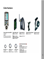
WRC-2
Wireless Remote Control 2 (WRC-2) Instruction Manual
Rev. 1.1, February 2008
Technical data are subject to change without notice.
Ident-No. K5.67651.0
ALL ARTWORK, PICTURES AND TEXTS ARE COVERED BY OUR COPYRIGHT.
THEY MUST NOT BE COPIED FOR REPRODUCTION (E.G. ON CD-ROM DISKS OR INTERNET-SITES) OR USED IN THEIR ENTIRE FORM OR IN EXCERPTS WITHOUT OUR PREVIOUS WRITTEN AGREEMENT.
IF YOU ARE DOWNLOADING PDF-FILES FROM OUR INTERNET HOME-PAGE FOR YOUR PERSONAL USE, MAKE SURE TO CHECK FOR UPDATED VERSIONS.
WE CANNOT TAKE ANY LIABILITY WHATSOEVER FOR DOWNLOADED FILES, AS TECHNICAL DATA ARE SUBJECT TO CHANGE WITHOUT NOTICE.
Order Numbers
Contents
1. Contents
2. Safety Instructions................................................ 6
2.1 Specific Safety Instructions.........................................7
3. Disclaimer..........................................................................8
4. Introduction........................................................................10
5. Setup...................................................................................12
5.1 WRC-2 in wireless mode............................................ 12
Transmitting.................................................................12
Receiving.....................................................................12
5.2 Mounting the WRC-2 on the WMU-3...........................13
5.3 - 5.4 Wireless Configurations.................................14
5.10 Wired Configurations............................................16
5.11 irect connection via the Camera Connector....... 16
5.12 Connection via Wireless Handgrip Attachment....16
5.13 Conection via Universal Remote Controller..........17
6. First Steps..........................................................................20
6.1 Powering up the Unit...................................................20
6.2 Using the Stylus..........................................................20
7. General Operation and Navigation..................................21
7.1 Touchscreen Navigation............................................ 21
7.2 Key Navigation............................................................21
8. Functions...........................................................................22
8.1 Introduction..................................................................22
8.2 Basic WRC-2 Menus...................................................22
9. Menu Structure..................................................................22
9.1 Introduction..................................................................23
9.2 Exit and Edit Buttons...................................................23
10. Main Menu........................................................................24
10.1 Starting a Software Module.......................................24
11. WRC-2 Settings Menu.....................................................25
11.1 Adjusting the Backlight Level.....................................25
11.2 Auto Dim Power Safe Function................................. 25
11.3 Calibrating the Touchscreen......................................25
12. Camera Control Menu.....................................................26
12.1 Introduction................................................................27
12.2 Status Window...........................................................27
12.3 Changing Camera Speed..........................................28
12.4 Editing Preset Speeds & Change Run Direction.......29
12.5 Changing Camera Mirror Shutter...............................28
12.6 Editing Preset Camera Shutter Angles......................31
12.8 Camera Control Options Sub-Menu........................33
Camera Direction..........................................................33
Beep Event...................................................................33
Beep Volume................................................................33
Length Unit...................................................................33
Time Code....................................................................33
12.9 Time Code Sub-Menu...............................................35
Time Code on/off..........................................................35
Time Code Sensitivity (TCS)........................................35
Time Code and User Bits..............................................35
Status Field...................................................................35
13. Lens Manager Menu........................................................36
13.1 Lens Manager Menu Functions..................................36
13.2 Administer Iris Tables..................................................37
13.3 Creating new Iris Tables using the Wizard.................38
14. Ramp Control Menu........................................................41
14.1 Enabling the Iris Control.............................................42
14.2 Programming a Ramp................................................43
14.3 Exposure Compensation............................................44
Compensation via the Mirror Shutter..........................44
Compensation via the Iris...........................................44
Mixed Compensation via Shutter and Iris...................44
14.4 Exposure Calculation..................................................45
Enable the Exposure Calculation...............................45
14.5 Compensation Free Style.......................................... 46
14.6 Ramp Options.............................................................47
Change Ramp Direction.............................................47
Save and Load a Ramp..............................................47
14.7 Ramp Example...........................................................48
Contents
12.7 Filmcounter Sub Menu.......................................... 32
Exposed Film Counter..................................................32
Take Counter................................................................32
Raw Stock Counter.......................................................32
Screen Time Display.....................................................32
Changing Units between Meter and Feet.....................32
15. External Display Menu....................................................49
16. Appendix..........................................................................50
16.1 Updating the Unit..................................................50
16.2 Service Menu........................................................51
16.3 Cleaning ..............................................................51
16.3 Troubleshooting....................................................52
16.4 Technical Data......................................................54
16.5 Declaration of Conformity.....................................54
16.6 ARRI Service........................................................55
17. Index.................................................................................56
Safety Instructions
2. Safety Instructions
Always follow these instructions to ensure against
injury to yourself and damage to the system or
other objects.
This safety information is in addition to the product
specific operating in snstructions in general and
must be strictly observed for safety reasons.
Warning signs
Possible risk of injury or damage to equipment
This symbol indicates the risk of electric shock or
fire danger that could result in injury or equipment
damage.
General Safety Instructions
Read an understand all safety and operating
instructions before you operate or install the
system.
Retain all safety and operating instructions for
future reference
Heed all warnings on the system and in the safety
and operating instructions before you operate
or install the system. Follow all installation and
operating instructions.
Do not use accessories or attachments that are
not recommended by ARRI, as they may cause
hazards and invalide the warranty.
Do not attempt to repair any part of the system.
Repairs must only be carried out by authorized
ARRI Service Centers.
Do not remove any safety measures of the
system.
Do not operate the system in high humidity areas
or expose it to water or moisture.
Operate the system using only the type of power
source indicated in the manual. Unplug the power
or connection cable(s) by gripping the plug, not the
cable.
Never insert objects of any kind into any part of the
system through openings, as the object may touch
dangerous voltage points or short out parts. This
could cause fire or electrical shock.
Unplug the system from the power outlet before
opening any part of the system or before making
any changes to the system, especially the attaching
or removing of cables.
Do not use solvents to clean the display screen.
Clean the display surface only with a soft, lint.-free
cloth or paper with water only. Wipe the screen
carefully. Do not spray liquid directly on the screen.
You may also use a mild glass cleaner that contains
no alcohol or ammonia.
Do not loosen screws that are painted over.
Specific safety instructions
Safety Instructions
Do not place the system on an unstable trolley,
stand, tripod, bracket or table. The system may
fall, causing serious personal injury and damage
to the system or other objects.
By using the WRC-2 you are able to run a connected
camera or other device. Therefore make shure
to follow all applicable safety instructions for the
connected devices.
Any violation of these safety instructions or the
nonobservance of personal care could cause
serious injuries (including death) and damage to
the system or other objects.
Disclaimer
3. Disclaimer
Before using the products described in this manual be
sure to read and understand all respective instructions.
The Wireless Remote Control 2, WRC-2, is only
availbale for commercial customers.
The customer grants by utilization, that the WRC-2 or
other components of the system are only deployed for
commercial use.
Otherwise the customer has the obligation to contact
ARRI preceding the utilization.
While ARRI endeavours to enhance the quality,
reliability and safety of their products, customers agree
and acknowledge that the possibility of defects thereof
cannot be eliminated entirely.
To minimize risks of damage to property or injury
(including death) to persons arising from defects in the
products, customers must incorporate sufficient safety
measures in their work with the system and have to
heed the statuted canonic use.
No part of this document may be copied or reproduced
in any form or by any means without written consent
of ARRI. ARRI assumes no responsibility for any errors
that may appear in this document.
The informations is subject to change without notice.
For product specification changes since this manual
was published, refer to the latest publications of ARRI
data sheets or data books, etc., for the most up-to-date
specifications.
Not all products and/or types are available in every
country. Please check with an ARRI sales representative
for availability and additional information.
damage to or replacement of equipment or property, any
costs or recovering of any material or goods associated
with the assembly or use of our products, or any other
damages or injury of persons and so on or under any
other legal theory.
No license, express, implied or otherwise, is granted
under any patents, copyrights or other intellectual
property rights of ARRI or others.
In the case one or all of the forgoing clauses are not
allowed by applicable law, the fullest extent permissible
clauses by applicable law are validated.
ARRI or its subsidiaries expressly exclude any libility,
warranty, demand or other obligation for any claim,
representation, or cause, or action, or whatsoever,
express or implied, wheter in contrat or tort, including
negligence, or incorporated in terms and conditions,
whether by statue, law or otherwise.
ARRI is a registered trademark of Arnold&Richter Cine
Technik GmbH & Co Betriebs KG.
Disclaimer
Neither ARRI nor its sbusidaries assume any liability for
infringement of patents, copyrights or other intellectual
property rights of third parties by or arising from the use
of ARRI products or any other liability arising from the
use of such products.
Note:
This product and the accessories recommended by the
manufaturer fulfil the specifications of the EU-Guidelines
89/336/EWG.
In no event shall ARRI or its subsidiaries be liable for
or have a remedy for recovery of any special, direct,
indirect, incidental, or consequential damages, including
but not limited to lost profits, lost savings, lost revenues
or economic loss of any kind or for any claim by third
party, downtime, good-will,
Introduction
4. Introduction
General Description:
The WRC-2 is a modern and user friendly remotecontrol and program unit for all new-generation
ARRIFLEX and ARRICAM cameras. It combines the
functionality of the RCU-1 and WRC-1. Beyond that,
the WRC-2 provides unique new features and due to
the touchscreen user interface, remote controlling a
camera was never faster and easier.
The range of functions is automatically adapted to
the attached camera. Since the functionality of the
WRC‑2 is software based and therefore expandable,
we are looking on the most flexible Remote Control
Unit, ARRI has ever provided.
Setups:
In the standard version, the WRC-2 enables the user
to remotely control
- the camera speed
- the shutter angle of the mirror shutter
providing a wide range of compensation options for
constant exposure via an easy an intuitive to use
software.
10
Automatic xposure Calculation:
Furthermore the WRC-2 automatically calculates the
correct exposure value for given ramps (speed, iris
or shutter) based on the measurements made by the
DOP on the set. This is a new and unique feature, only
available through the WRC-2. The complete ramp
data can now easily be entered in the clear arranged
Ramp Menu, guiding the user through the sometimes
very complex process of programming a ramp. Thus,
the WRC-2 is a very powerful tool that saves time
and provides a new level of exposure‑safety and
precision.
Simulator Software:
To make yourself familiar with the unit before using it
on the filmset, we offer a WRC-2 simulator software,
that can be downloaded via our website.
Upload new Software Modules:
New released software modules or software updates
can be uploaded just by connecting an USB stick to
the WRC‑2 mini-USB port.
Introduction
Ramp Compensation with and without LDS Lenses:
The WRC-2 can automatically compensate speed
and iris ramps. In order to compensate the ramps by
the iris, a CLM-1 or CLM-2 motor has to be attached
to the camera and the mounted lens has to be
selected in the WRC-2. This is done automatically
when using LDS lenses (Master Prime or LDS Ultra
Prime). For other lenses an Iris Table can be easily
created following a few steps in the Lens Manager.
The lens can then be stored in the WRC-2 internal
memory.
Modular System
The WRC-2 works with the ARRI Wireless Remote
Control system and attaches to the Wireless Main
Unit WMU‑2 and WMU-3.
It can be wired to an ARRIFLEX or ARRICAM either
directly or via a Wireless Handgrip Attachmend
WHA–2 or WHA-3 using a standard LCS cable.
The knob module can be removed to keep the unit as
small as possible, if desired.
11
Setup
5. Setup
5.1 WRC-2 in wireless mode
Transmitting:
In order to be able to use the WRC-2 in wireless
mode, it must be mounted on a Wirless Main
Unit (WMU-2 or WMU-3) as a transmitter. The
Main Unit supplies the WRC-2 with power and
establishes the radio link with the camera.
Up to three WMU can be used simultaneously,
therefore the WRC-2 can be controled by one
operator while e.g. the focus unit can be controlled
by another operator. Please refer to the LCS
instruction manual for further details.
Receiving:
On the camera side, a receiver is needed. When
using ARRICAM cameras, the receiver is built
in the Lens Data Box. When using 435, the
receiver is the Universal Radio Module (URM-3).
This device has to be mounted to the Function
Expansion Module (FEM-1 or FEM-2) When
using other cameras, the Universal Radio Module
(URM-3) can be used as a receiver.
12
● Switch off the Wirless Main Unit WMU by pressing
the ON/OFF button.
● With the wide black pin pointing forward, insert the
WRC-2 into the free space on the WMU. Then press
the WRC-2 onto the WMU until the module audibly
snaps into position.
● Select the same radio channel on the WMU and on
the receiver (e.g. Lens Data Box)
Setup
5.2 Mounting the WRC-2 on
the WMU-3 or WMU-2
Note:
The WRC-2 can not be mounted on a WMU-3
together with other modules without using the
Wireless Expansion Bracket (WEB-3).
Note:
Do not seperate the hand control units from one
another when they are switched on, as this can
result in randomly set lens limits.
13
Setup
5.3 Wireless Configurations
5.4 WRC-2 & ARRICAM Studio and Lite
On the ARRICAM Lite and Studio a Lens Data Box
(LDB) has to be mounted in order to be remotely
controlled by the WRC-2 via the Wireless Main
Unit WMU-3 or WMU-2.
Functions:
- Speed, Shutter, Cam Info, LDS Info
- Ramp Control: Enter Speed and Shutter
Compensation by Iris* and/or Shutter
5.5 WRC-2 & ARRIFLEX 435 Xtreme / Advanced
On the FEM-2 the Universal Remote Controller
URM-3 has to be mounted.
Functions:
- Speed, Shutter, Cam Info, LDS Info
- Ramp Control: Enter Speed and Shutter
Compensation by Iris* and/or Shutter
*) if CLM-2 or CLM-1 motor is connected to
the Lens Data Box (LDB)
14
Setup
5.6 WRC-2 & ARRIFLEX 416
On the ARRIFLEX 416 the 416 PLUS
Electronics Side Cover has to be mounted
(included in 416 PLUS).
Functions:
- Speed, Cam Info
- Ramps: Speed
Compensation by Iris if CLM-2 or CLM-1 motor
is connected to the Electronics Side Cover.
5.7 WRC-2 & other ARRI Cameras
In order to control cameras without a bulit in
receiver (e.g. Lens Data Box on ARRICAM)
the Universal Remote Controller has to be
connected to a camera with the cable KC-97
for the 235 and 416 or with the cable KC-99 for
435, 535B and 16SR3 or 16SR3 HS.
Functions:
- Speed, Iris*, Shutter**
- Ramp Control: Enter: Speed, Iris*, Shutter**
*) if CLM-2 or CLM-1 motor is connected to
the Lens Data Box (LDB)
B
**) if camera has an electronic adjustable
mirror shutter
15
Setup
5.10 Wired Configurations
Camera Connector
The WRC-2 can be wired to a camera or to a Universal
Motor Controller UMC-3 in three different ways:
5.11 Direct connection via the
Camera Connector
to ARRICAM Studio and Lite: KC-125
to ARRIFLEX 235, 416, 435, 535, SR3 (HS):
KC-39 (1,5m/5ft) or KC-41 (20m/60ft):
KC-125
KC-39 or KC-41
5.12 Connection via the Wireless Handgrip
Attachment WHA-2 or WHA-3
To connect the WRC-2 to the LCS Bus the Wirless
Handgrip Attachment WHA-2 or WHA-3 has to be
mounted on the back of the WRC-2.
*LCS Bus = Lens Control System interface. ARRI
Cameras and accessories can be connected. The
bus can be recognized by the red sockets and red
plugs. See next page for a list of LCS cables.
16
LCS Cable
Setup
5.13 Connection via the
Universal Remote Controller URM-3
The UMC-3 can be connected to the WRC-2 either
directly via the WRC-2 Cam Cable or via the mounted
Wireless Handgrip Attachment WHA-2 or WHA-3 and
an Lens Control Cable (e.g. LC-Z1/Z2 or LC-M1/M2).
Both cables are pluged into the „LCS“ socket of the
UMC-3.
The cameras can then be wired to the UMC-3 („CAM“
socket) via two different cables:
KC-97: to ARRIFLEX 235 and 416
KC-99: to ARRIFLEX 435, 535, 16SR 3 (HS)
LCS Cables
LC-Z1 (3,5m/11ft) LC-Z2 (7m/23ft) LC-M1 (1m/3ft)
LC-M2 (2m/6ft)
K4.41395.0
K2.41396.0
K4.41397.0
K2.43871.0
17
Setup
5.14 WRC-2 & ARRICAM Studio and Lite
Possible Connections:
1.) Via KC 125 direct to ARRICAM Studio or Lite.
2.) With WHA-2/3 attached to WRC-2 via LCS
cables. (A Lens Data Box has to be mounted)
Functions:
- Speed, Shutter, Cam Info, LDS Info
- Ramp Control: Enter Speed and Shutter
Compensation by Iris* and/or Shutter
5.15 WRC-2 & ARRIFLEX 435 Xtreme / Advanced
Possible Connections:
1.) Via KC-39 or -41 direct to 435 Xtreme/Adv.
KC-39 (1,5m/5ft) or KC-41 (20m/60ft)
2.) With WHA-2/3 attached to WRC-2 via LCS
cables. (FEM-2 has to be mounted)
Functions:
- Speed, Shutter, Cam Info, LDS Info
- Ramp Control: Enter Speed and Shutter
Compensation by Iris* and/or Shutter
*) if CLM-2 or CLM-1 motor is connected to
the Lens Data Box (LDB)
18
KC-125
LCS Cable
KC-39 or KC-41
LCS Cable
Setup
5.16 WRC-2 & ARRIFLEX 416
Possible Connections:
1.) Via KC-39 or -41 direct to 416.
KC-39 =1,5m/5ft, KC-41 =20m/60ft
2.) With WHA-2/3 attached to WRC-2 via LCS
cables. (416 Plus only)
Functions:
- Speed, Cam Info
- Ramps: Speed, Iris (needs CLM-1 or -2)
5.17 WRC-2 & other ARRI Cameras
In order to control cameras without a bulit in
receiver (e.g. Lens Data Box on ARRICAM)
the Universal Remote Controller has to be
connected to a camera with the cable KC-97
for the 235 and 416 or with the cable KC-99 for
435, 535B and 16SR3 or 16SR3 HS.
Functions:
- Speed, Iris*, Shutter**
- Ramp Control: Enter Speed, Iris*, Shutter**
B
*) if CLM-2 or CLM-1 motor is connected to
the Lens Data Box (LDB)
**) if camera has an electronic adjustable
mirror shutter
19
Introduction
6. First Steps:
6.1 Powering Up The Unit
After connecting the WRC-2 to a camera the WRC2
will power up automatically and the last used menu
will be displayed.
KC-115
KC-39 / KC-41
ARRICAM Studio and ARRICAM Lite
ARRIFLEX SR3, 416, 235, 435, 535B
Main Menu
To go back from any menu to the Main Menu,
click „Exit“ or „Cancel“ until the Main Menu appears.
6.2 Using the Stylus
Just as you use a mouse pointer to click elements
on a computer screen, you can use the stylus to tap
elements on your WRC-2‘s touch-sensitive screen.
Tapping is the basic action used to execute tasks on
your WRC-2. Alternatively you can use your finger.
However, in this manual both actions are described
as „click“.
Note:
Do not use a pen, pencil or any other sharp object
to click on the screen.
We recommend to use a screen protector.
20
Stylus
The operating software can be controlled in two
ways.
PC and USB sockets
Camera Connector
7.1 Touchscreen Navigation
1.) Direct control via the „Touch screen“. Simply
click on the icons, sliders or other menu buttons
with the on-board Stylus or your finger. To
release the Stylus, press the „Stylus Release
Button“ on the right side of the WRC–2.
7.2 Key Navigation
2.) Navigate through the menus with the
„Arrow Buttons“ and use the „Function Keys“
to activate the buttons copied in the software.
For example: Instead of clicking on the „Edit“
button on the Touch Screen, just press the left
„Function Key“.
Use the left and right Arrow Buttons to jump
from item to item, use the up and down
Arrow Buttons to change values or to operate
sliders.
Lock/Unlock
To lock/unlock the keypad, press the Lock/
Unlock Key for three seconds.
Stylus (Pen)
Stylus Release
Button
Introduction
7. General Operation and Navigation
Touchscreen
Function Key
Arrow Button
Run Button
Function Key
Lock/Unlock Key
Ramp Button
Knob
Marking Disk
21
Functions
8. Functions
8.1 Introduction
The WRC-2 not only replaces camera control
accessories like WRC-1, RCU-1 or the External
Display EXD-1. By using special software modules
for each task, it provides many other new features
and possibilities. The Software Modules are called
„Menus“ and can be started from the „Main Menu“ in
the WRC‑2.
Future software releases and menus can be uploaded
to by connecting an USB memory stick to the WRC-2.
Depending on the number of Software Menus you have
uploaded, the Main Menu will vary. For information
about future releases, please refer to the manual
updates that will be shipped with each Software.
8.1 The Basic WRC-2 contains the following
Menus:
Camera Control
Contains all camera related controls:
- Edit camera speed and shutter.
- Set filmcounters and other options
22
- Edit time code settings.
- Edit camera speed/direction and shutter.
Ramp Control
- Enter Speed or Iris Ramps.
- Set Compensation (Iris, Shutter or Mix).
- Calculate the actual exposure value .
- Calculate Screen Time.
Lens Manager
- Edit, save and load Lens Tables
- Calibrate lenses
External Display
- Provides the Camera Menu on the
WRC-2 display
WRC-2 Settings
- Set the backlight level.
- Calibrate the touchscreen.
- Perform software updates.
Functions
9. Menu Structure
9.1 Introduction
From the Main Menu all other
applications can be launched by
clicking on the corresponding icons.
Depending on the amount of
functions, some Menus can contain
Sub-Menus.
To navigate back to the Main Menu,
click on „Exit“ or „Cancel“ in the
Menus or Sub-Menus until the Main
Menu is displayed again.
Camera Control
Chapter 12
Ramp Control
Chapter 14
LensManager
Chapter 13
„Exit“ and „Edit“ Buttons
● „Exit“ will safe your changes
and inputs and jump back to the
preceding menu. Click „Edit“ to
change the values.
● „Cancel“ will not safe your inputs
but jump back to the preceding
menu.
Main Menu
Chapter 10
External Display
Chapter 15
WRC Settings
Chapter 11
23
Main Menu
10. Main Menu
10.1 Starting a Software Module
In the „Main Menu“ all available software
modules represented by a corresponding icon
are displayed. If you have installed further
applications, their icons may not be visible
without using the slider on the right side.
Alternatively you can always use the arrow
keys to move from one icon to another. Start
the application by using the left „Function Key“
or just click on the icon with the stylus or your
finger.
To navigate back to the „Main Menu“ from
anywhere in other software modules, just
click „Cancel“ or „Exit“ until the „Main Menu“
appears.
Note: The WRC-2 will always power up with
the last menu that was used in the preceding
session.
24
Icons
Main Menu
In the Settings Menu the display backlight level and
Auto Dim durations can be set. Also the display can be
calibrated to asure a precise control with the stylus.
11.1 Adjusting the backlight level:
● In the Main Menu, click „WRC Settings“
● Use slider to adjust the backlight level.
11.2 Auto Dim (Backlight level) Function
● Select a time from the Auto Dim Listbox . The screen
will darken to the lowest possible setting after that
time to save battery energy. As soon as you touch
either the display or press any key, the brightness of
the display will jump back to the level previously set
on the slider.
11.3 Calibrating the touchscreen:
● In the WRC Settings Menu, click „Calibrate“
● Click on the cross-symbols precisely
● After calibration click on „Test“. Draw some lines on
the screen to check the precision of the stylus.
● Click „Exit“ to go back to the Main Menu.
Main Menu
WRC Settings Menu
11.4 Service Menu / Updating the Unit
● In the WRC Settings Menu, click „Service“
● Refer to Appendix Chapter 15.1 Service and
Maintenance
Camera Control Menu
11. WRC-2 Settings Menu
25
Camera Control Menu
12. Camera Control Menu
12.1 Introduction
This menu represents a complete camera
remote control and status monitor. On the left
side in the „Settings Window“ you find editable
values like speed, shutter and filmcounters.
Also other camera related options can be set
and edited via the „Options“ button.
The „Status Window“ is on the right side. It
offers an overview about the actual camera
status and can display error or warning
messages in detailed text form.
When working with the Lens Data System, the
iris values will be displayed in the Lens Data
Information field.
When using a Non-LDS-Lens an Iris Table can
be created and loaded in the Lens Manager
in order to display the actual iris values in the
Status Window.
26
Settings Window
Status Window
Speed
General Lens
Information
Shutter*
Iris*
Filmcounter
Messages &
Warnings
Options
Lens Data
Information
Phase
Button
Camera Control Menu
On the right side of the screen, the actual camera
status is displayed. The color of the screen can alter:
cyan = standby
green = camera running
orange= inching
red = warning or not ready
The following values and settings are displayed:
Battery Voltage
Displays the Voltage value.
PS/CCU
Displays the camera setting PS/CCU or NORM. In
order to be able to change the speed settings, the
camera has to be set to PS/CCU.
When the camera is switched to NORM mode, all
other options are available (shutter, iris etc.).
LDS: e.g. 40mm T1.9
In this case, a 40mm LDS Ultra Prime is connected
to the camera. The widest f-stop is T1.9
Note: This f-stop value is not the actual f-stop, set
on the lens.
Message & Warnings Field
Error Messages will be displayed here.
Iris
The Iris value, that is actually set on the lens.
Camera Control Menu
12.2 Status Window
27
Camera Control Menu
28
12.3 Changing Camera Speed
In the camera control menu, the camera speed can
be edited. There are two ways to edit the camera
speed. The fastest is to choose from preset values.
But also specific values can be entered.
To choose from a preset camera speed
Choose from a preset camera speed:
● In the Camera Control Menu, click on the arrow
button in the „Speed“ section, the Set Speed(fps)
Menu will appear.
● Click on the desired value in the speed list, the
value will be displayed in the small window on the
top.
● Confirm the value by clicking on „Set“.
To edit a specific camera speed
Enter a user defined camera speed
● In the Camera Control Menu, click on the arrow
button in the Speed section.
● In the Set Speed(fps) Menu, click on „Edit“.
● Enter the desired value. Use the arrow buttons to
navigate or „C“ to clear the input.
● Click „Set“ to set the new camera speed.
Delete items from the preset list:
● In the Set Speed Menu, click on value you want to delete.
● Click on „Delete Item“
Add a user defined speed value:
● In the Set Speed Menu, click on „Edit“.
● Enter your speed value and click on „Set“.
● Click on „Add Item“, the new value will appear in the list.
Add all default speed values
● In the Set Speed Menu, click on „Add Defaults“.
All preset values will be added to the list.
Change Camera Direction
For forward run, check the „Forward“ button.
For reverse run, check the „Reverse“ button.
You will have to confirm the change.
Camera Control Menu
12.4 Editing Preset Speeds & Change Camera Direction
29
Camera Control Menu
12.5 Changing Camera Mirror Shutter:
From the camera control screen, the camera shutter angle
can be edited. There are two ways to edit the shutter angle.
The fastest is to choose from preset values. But also specific
values can be entered.
Note: Before changing the mirror shutter values make sure
the locking mechanism is set to the LOOSE (unlocked)
position. Please refer to the corresponding camera
manual.
Choose from a preset camera shutter angle:
● In the Camera Control Menu, click on the arrow button
in the „Shutter“ section.
● The Set Shutter Menu will appear.
● Click on the desired value, the value will be displayed in the
small window on the top.
● Confirm the value by clicking on „Set“.
Edit a specific camera shutter angle
● In the Camera Control Menu, click on the arrow button
in the Shutter section.
● In the Set Shutter Menu, click on „Edit“.
● Enter the desired value. Use the arrow buttons to navigate
or „C“ to clear the input.
● Click „Set“ to set the new camera shutter angle.
30
To choose from a preset camera speed
To edit a specific camera speed
Delete items from the preset list:
● In the Set Shutter Menu, click on value you want to delete.
● Click on „Delete Item“
Add a user defined shutter angle value:
● In the Set Shutter Menu, click on „Edit“.
● Enter your shutter angle value and click on „Set“.
● Click on „Add Item“, the new value will appear in the list.
Add all default camera shutter values
● In the Set Shutter Menu, click on „Add Defaults“.
All preset values will be added to the list.
Camera Control Menu
12.6 Editing Preset Camera Shutter Angles
31
Camera Control Menu
12.7 Filmcounter Sub-Menu:
The WRC-2 provides three film counters and calculates the
corresponding screen time.
Exposed Film Counter:
Displays the total amount of exposed film.
Click „Reset“ to set counter to zero.
Take Counter
Counts only the take length and resets itself to zero after
running the camera.
Raw Stock Counter
Will display the raw stock quantity that was preset on
th camera (ARRIFLEX 416) or via the magazine
(ARRICAM)
Screen Time Display
Calculates the screen time at 24 fps. The screen time is
the time needed for the projection of the shot with 24fps,
regardless of the camera speed.
Changing the unit of measurement (meter/feet)
Please refer to the next chapter: Camera Control Options
32
Camera Control Menu
Options Sub-Menu
To enter the Options Menu click „Options“ in the Camera
Control Menu
Camera Direction
Enables the change between forward and reverse run
Beep Event
Defines when the beep signal should occur.
Beep Volume
Sets the volume of the beep signal.
Camera Control Menu
Options Sub-Menu
Length Unit
Sets the general lenght unit to meter or feet.
Camera Control Menu
12.8 Camera Control Options Sub-Menu
Time Code
Refer to the Chapter „Time Code Sub-Menu“
Time Code Sub-Menu
33
Camera Control Menu
12.9 Time Code Sub-Menu
Since the WRC-2 only remote controls the time code
settings of a particular ARRI camera, please refer to the
individual camera manual for detailed information about
time code recording.
To enter the Time Code Sub-Menu:
- In the Camera Control Menu click „Options“
- In the „Options Sub-Menu“ click „Time Code“
Time Code on/off
Enables time code recording.
(Only if camera and magazine allow TC exposure)
Camera Control Menu
Options Sub-Menu
TCS (Time Code Sensitivity)
Displays the TCS settings from the camera or magazine.
The TCS value descibes the intensity of the time code
recording to suit the sensitivity of different film stocks.
For the correct TCS settings please refer to the corresponding
camera manual or to the -time code exposure sensitivitytables provided as PDF files in the download section on
www.arri.com.
Time Code Sub-Menu
34
Time / User Bits
Shows and sets the time code clock and user bits to the
desired values.
Warnings
Displays warnings in text form by clicking on the down arrow
button on the keypad.
Time Code Sub-Menu
35
Lens Manager Menu
13. Lens Manager Menu
13.1 Lens Manager Menu Functions
In order to compensate ramps via the iris or to display
iris values in the Camera Control Menu, one of the
following two requirements must be fulfilled:
1.) Using a Lens with Lens Data System:
In this case the iris information will be transfered via a
Lens Control System (LCS) Unit to the camera.
LCS Units are e.g.: Lens Data Box, FEM-2, UMC-3 or
ARRIFLEX 416 Plus (electronics side cover). Therefore
creating an Iris Table is not necessary.
To register and calibrate the lens:
● Connect a lens motor to the LCS Unit.
● Start the calibration process via the „CAL“ Button in
the Lens Manager Menu.
Alternatively the CAL button on the WHA-2/3 or
WMU‑2/3 can be used. If no ramp compensation is
intended, the iris ring of the LDS ring can be turned
to enable the display of the iris values in the Camera
Control Menu.
2.) Using a Lens without LDS:
In this case, an Iris Table for the Non‑LDS‑Lens has
to be created manually in the Lens Manager Menu and
36
loaded into the LDB or Universal Remote Controller
(UMC-3). See Chapter 13.2.
All created Iris Tables will be stored permanently in the
internal flash‑memory of the WRC-2 and simultaneously
displayed in the User Iris List for a quick access.
Iris Tables can be removed from the User Iris List for
a better clarity, however, they will remain stored in the
User Folder System from where they can be added to
the User Iris List again.
Camera Status Line
Iris Table Status Line
Calibration Button
Created Iris Tables
Access to User
Folder System
Lens Manager Menu
Create new Iris Tables
● Click on the headword „<new>“ in the User Iris List
and click „Edit Iris Table“. This will start the Iris Table
Wizard. See chapter 13.3 to use the Wizard.
Load Iris Tables
● Click on the Iris Table in the User Iris List.
● Click „Load Table“.
● Insert the lens into the camera lens mount.
● Connect the lens motor to the LDB or UMC-3
● Click on „CAL“ to calibrate the lens.
Remove Iris Tables from the User Iris List
● Click on the Iris Table in the User Iris List.
● Click „Remove“. The Table will disapear from the
User Iris List but will remain stored in the User
Folder System.
Note:
To keep the lens list as clear as possible, store only
the currently and frequently used lenses in the User Iris List.
Add Iris Tables from the User Folder System
● Click on „Add Existing“
● In the User Folder System Menu, click on the desired
Iris Table.
● Click on „Open“. The Iris Table will appear in the
User Iris List.
Erase or Rename Iris Tables
● Click on „Add Existing“
● In the User Folder System Menu, double-click on the
desired Iris Table.
● From the PopUp Menu select „Delete“ or „Rename“
Note: Deleting an Iris Table from the User Folder
System can not be made undone.
Lens Manager Menu
13.2 Administer Iris Tables
Loaded Table Status Line
Displays the last Iris Table that was uploaded to the
LCS Unit. The Iris Table will remain stored in the
LCS Unit memory (LDB, FEM-2, UMC-3, 416 Plus
etc.) even after powering off the unit.
CAL Button
Click on the „Cal“ button to calibrate the lens.
37
Lens Manager Menu
38
13.3 Creating new Iris Tables with the Iris Table Wizard
● Click on the headword „<new>“ in the User Iris List and
click „Edit Iris Table“. This will start the Iris Table Wizard.
Step 1
Enter the range of your iris
Step 2
Mount Lens Motor and Calibrate
Step 3
Toggle stop position
Some lenses may have a „CLOSE“
position where the iris is shut
completely. If so, check „Yes“ in the
box.
● Enter open and close iris values
of your lens.
● Attach a Controlled Lens Motor
(CLM-1/2) to the LDB or UMC.
● Start calibration.
Depending on how the lens was
mounted the iris may not be in the
open position at this stage.
Note: Alternatively the buttons
on WMU-2/3 or WHA-2/3 can be
used.
● Click Toggle if the iris is not on
the open position.
Step 5
Name the Iris Table
● Make sure the iris is set to the T‑Stop marked by the yellow
arrow (e.g. f1.9). Use the knob of the WRC-2 to adjust the
position. Alternatively you can use the slider on the bottom
of the screen.
● Click „Set“ to assign the postions to the iris.
● Go ahead like this until all T‑Stops are assigned. If necessary,
click on „Back“ or „Next“ to reassign the positions.
● Set at least five T-Stops. When the yellow arrow is at the last
position, click next to finish the process.
● Enter an appropriate name for the
iris table including lens type, focal
lenght and some last digits of the
serial number.
(e.g. „UP_50mm_1234)
● Click „Finish“
● To activate the Iris Table, go to the
Lens Manager Menu and load the
Iris Table (see Chapter 13)
Lens Manager Menu
Step 4
Define the T-Stop positions
39
Page intentionally left blank
40
In the Ramp Control Menu speed and shutter ramps
can be programmed. After enabling the Iris Control,
also iris ramps can be performed. If a speed ramp is
to be compensated by iris and shutter simultaneously,
the ratio of both values can be mixed via the
Compensation Mix Slider.
The actual status and position of the ramp is shown
in the Ramp Display by the yellow arrows. When
the ramp is performed, the arrows move along the
ramp display from the start values to the end values
providing a clear situational awareness of the running
ramp.
The Exposure Calculator helps calculating the working
T-stop. Simply measure the light on the set with your
light meter and standard settings (e.g. 24fps, 250ASA)
and enter the measured T-stop in the calculator (Tstop input window). The working T-stop that has to be
set on the lens will then be computed and displayed
in the Ramp Display. When the Iris Control is enabled,
the iris will be set automatically to the correct value via
the lens motor.
Status Window
Compensation
Mix Slider
Ramp
Display
Ramp
Time
Selector
Ramp Control Menu
14. Ramp Control Menu
T-stop input window for
Exposure Calculator
41
Ramp Control Menu
14.1 Enabling the Iris Control
In order to compensate ramps via the iris or to program
an iris ramp, please check if:
1.) The Iris Table is activated in the Lens Manager
To activate an Iris Table navigate to the Lens
Manager. Please refer to chapter 13.
2.) The Iris Control is enabled.
To enable the Iris Conrol:
● In the Set Ramp Menu, click on „Options“.
Ramp Control Menu
● In the Options Menu, click on „Enable Iris Control“.
If you can not activate the checkbox, no lens is
mounted. Please navigate to the Lens Manager
(see Chapter 13) and mount a lens.
Note:
When the Iris Control is enabled, the iris motor will
set the iris automatically to the value entered in
the Ramp Control Menu. To manually set the iris,
switch the Iris Control off.
Ramp Options Menu
42
● Select the desired speed ramp function by clicking on
the corresponding control button. (e.g. „Speed“)
● Click on the start and end values of the ramp display
to edit the values. (e.g. 6fps and 96fps)
The ramp will always be perfomed from top to bottom.
Therefore in this example the upper value will be
the initial camera speed (6fps). The yellow marker
displays the current camera speed.
● Click in the Ramp Time Window to select the timing
control:
„Time“
= A user defined ramp time can be set
„Time min“ = The fastest ramp will be computed and set by the WRC-2 automatically.
„Knob“
= The ramp can be controlled manually
via the WRC-2 Knob / Handwheel.
Ramp Control Menu
Ramp Control Menu
14.2 Programming a Ramp
● After running the camera the ramp can be performed
by pushing the „Ramp“ button on the WRC-2
Make sure the keypad is not locked. To unlock the
pad press the „Lock/Unlock“ key for three seconds.
- To compensate the Speed Ramp refer to 14.3
- To change the Ramp Direction refer to 14.5
43
Ramp Control Menu
14.3 Exposure Compensation
Via the Ramp Menu three different
compensation methods can be selected:
exposure
1.) Compensation via the Mirror Shutter
The camera has to be outfitted with an electronic
adjustable mirror shutter.
● Check the compensation box of the shutter ramp
display. The shutter values will be computed by the
WRC-2. (e.g. 11,25 to 180 degrees)
2.) Compensation via the iris
A CLM-1 or CLM-2 motor needs to be mounted to the
camera and an iris table must be activated. Refer to
chapter 15.
● Check the „Iris“ box of the iris ramp display. The iris
values will be computed by the WRC–2
3.) Mixed Compensation via Shutter and Iris
● Check both the „Iris“ box and the „Shutter“ box of
the ramp display. Use the Compensation Mix Slider
to adjust the ratio between iris and shutter in 5%
steps. To adjust the values in 1% steps, use the
Arrow Buttons on the WRC-2.
44
Ramp Control Menu
Red values:
The ramp calculation can result in values that can not
be accepted by the currently used camera or lens, e.g.
T-stop 32, or 10degree shutter angle.
In this case the value will be displayed in red.
Change the basic values, e.g. the speed, to keep the
calculated values in an acceptable range.
Example:
A speed change from 1 to 128 fps with shutter
compensation only is not possible since for
compensation seven T-stops are necessary (1-2-48-16-32-64-128fps), but the shutter can only provide
four stops (180° -90°-45°-22,5°-11,25°). To solve the
problem, either reduce the speed range or enable the
iris compensation additionally.
The exposure calculation is a very powerful feature of
the WRC-2. It reduces the workload of a ramp exposure
calculation to a simple transfer of the exposure value
from a light meter to the WRC-2.
Once the working f-stop for a shot is determined by the DP
and entered in the WRC-2, all exposure compensations
will be calculated automatically.
To Enable the Exposure Calculation:
● In the Ramp Menu click on „Options“
● Check „Enable“ in the Exposure Meter Window
● Enter speed and shutter values of the exposure meter
that is used on the set. (values will be stored)
● Click „Exit“ to go back to the Ramp Menu
Ramp Options Menu
Ramp Control Menu
14.4 Exposure Calculation
Use the Exposure Calculation:
● Measure the light to determine the working f-stop.
● Click on the „Exposure Meter“ Window and enter the
working f-stop by using the sliders.
● Read the calculated f-stop in the Iris Display and set
the iris value on the lens.
Note: Since there is no compensation selected,
the current settings will lead to a two stop
underexposure. See the Exp. Diff. (Exposure
Difference) indicator window.
Ramp Control Menu
45
Ramp Control Menu
14.5 Compensation Free Style
After selecting a compensation method for a desired ramp
(e.g. 100-25fps) the WRC-2 will compute the necessary
compensation values (e.g. 180°-90° and T2.8-T4). The
„Compensation Free Style“ mode enables the user to
edit all values of a ramp independently, regardless of the
exposure compensation. With the „Exposure Meter“ on,
the ramp entry values (e.g. 100fps, 180°, T2.8) will still
be computed but they can now also be changed. The
resulting over- oder underexposure will be displayed by
the „Exp. Diff“ indicator (Exposure Difference)
Enable „Compensation Free Style“
● In the Ramp Control Menu, click on „Options“ to enter
the Ramp Options Menu.
● Activate „Comp Free Style“
● Click „Exit“ to go back to the Ramp Control Menu
● In the Ramp Control Menu, click on the desired value
(in our example we want to change the T-stop value
from T4 to T8)
Note the „Exp. Diff“ (Exposure Difference) indicator. After
changing the f-stop from T4 to T8, the indicator will show
„-2.0“. That means, with the current setting, the result
will be a two stop underexposure.
46
Ramp Options Menu
Ramp Control Menu
Ramp Control Menu
In the Ramp Options Menu the Exposure Calculation and
Iris Control can be enabled. Also the Ramp Direction can
be changed and ramps can be saved and loaded.
● In the Ramp Menu click on „Options“ to enter the
Ramp Options Menu.
Change Ramp Direction:
● Click on „Change Ramp Direction“ in the Ramp
Window and confirm the safety message.
Ramp Control Menu
Set to Default
● Will reset all ramp parameters to a standard speed
ramp to provide a basic setting.
Ramp Control Menu
14.6 Ramp Options
Safe and Load a Ramp
Save a Ramp
● Click on „Save Ramp as“ to save the actual Ramp.
Note the name of the folder.
Load a Ramp
● Click on „Load Ramp“ and navigate to the folder where
the Ramps are saved.
Ramp Options Menu
47
Ramp Control Menu
48
14.7 Ramp Example
Even though the WRC-2 can compute the correct
exposure values, a proper planning of the ramp is
recommended to understand and follow the calculations.
For this example we assume the following:
- The director wants to change the camera speed
between 3 and 24 fps manually.
- The exposure should be compensated by iris and
shutter simultaneously.
- Set up the WRC-2 and acquire the correct f-stop.
The WRC-2 could be set up as follows:
1.) In the Main Menu click on „Lens Manger“. Make
sure that the used lens is loaded and calibrated (see
Chapter 15) otherwise the iris compensation will not
be available.
2.) Start the Ramp Control Menu (from Main Menu).
3.) Click on „Options“ and enable the Ramp and
Exposure Meter Controls. Measure the light to
acquire the working f-stop and enter the value in the
yellow window. Make sure your lightmeter is set to
1/50 second or 24/25fps. Click EXIT to confirm.
4.) Click on „Speed“ and enter the start value „3“ and
the end value „24“ frames per second.
5.) Select „Knob“ from the Ramp Time Window to
enable the manual speed change.
6.) Activate „Shutter“ and „Iris“ compensation and
move the slider in the middle position to mix the
compensation ratio to 50% Iris and 50% Shutter.
Use the Arrow Buttons to adjust in small steps.
7.) Confirm the working f-stop or enter a new one if
the light has changed.
8.) Start the camera by pressing the RUN button and
control the speed change by turning the knob.
6
4
7
5
Ramp Control Menu
The External Display Menu remote controls the camera
menu and shows the same information as screened on
the camera display.
Note: The External Display Menu can only be used with
cameras provided with an LCD display.
(e.g. ARRIFLEX 435, 535, 16SR-3, 416).
Thus the External Display Menu can neither be used
with ARRICAM Studio or ARRICAM Lite, nor with older
ARRIFLEX cameras without an LCD display (e.g. SR-2,
SR-1, BL-4 etc.)
Main Menu
● In the Main Menu click on the ikon „External Display“
to open the Menu.
● Click on „Mode“ to navigate to the next mode.
● To change a value: Click on „SEL“ until the desired
value starts to flash.
● Click „Set“ to change the value.
● Wait until the value stops flashing or click „Mode“ to
confirm the new setting.
External Display Menu
15. External Display Menu
External Display
49
Appendix
16. Appendix
16.1 Updating the WRC-2
● Connect an USB Stick with the update software to
the mini-USB connector „MEM“ of the WRC‑2. Use
the provided adapter cable to adapt from an USB
stick to the Mini-USB connector.
Main Menu
WRC Settings Menu
Update Menu
Service Menu
● Open the WRC-2 Settings Menu.
● Click „Service“.
● Click „SW Update“.
● Check if version from memory stick is displayed.
If not, check USB stick connection.
● Click „Update“ to upload the new software.
● Click „OK“. The unit will boot with the new software.
50
16.3 Cleaning
Exit from App.
For service personnel only.
Cleaning the Touchscreen
● Any standard glass cleaner can be used to clean
the touchscreen, but avoid products containing
ammonia. Always spray the glass cleaner on the
cloth or towel and then clean the touchscreen. Glass
cleaner sprayed directly on the unit could possibly
leak inside and cause damage.
Adjusting the Knob (Handwheel)
For service personnel only :
● Turn the knob to the left end stop and press „Adjust
left“, then turn the knob to the right end stop and
press „Adjust right“.
● Turn the knob from end stop to end stop and check
if the values change correspondingly.
Appendix
16.2 Service Menu
File Dialog
For service personnel only.
51
Appendix
16.4 Troubleshooting
Communication Problems:
In the event of a communication failure between the
WRC-2 and the LCS Device or the Camera, the EDIT
button will turn red and a dot will run across the text.
To solve the problem, check all cable connections and
restart the unit.
When using the WRC-2 wireless via a WMU-3 or
WMU‑2, try the following:
1.) Connect both units, receiver (e.g. Lens Data Box)
and transmitter (e.g. WMU-3) via the WC–A3 antenna
cable to eliminate possible transmitting errors.
2.) Select a different channel on transmitter and receiver
and restart the camera.
Wait for a flashing green RF signal on the LCS unit (FEM2, LDB, UMC-3 etc) and then restart the WMU‑3.
52
No Speed setting available:
Check if the camera is set to „PS/CCU“ and not to
„NORM“.
Appendix
Page intentionally left blank
53
Appendix
16.5 Technical Data
Dimensions
Length
200mm (7.87“)
Width
76.6mm (3.02“)
Height
27.3mm (1.07“)
Weight approx. 460g with knob mounted
Power Supply
Acceptable Voltage Range 7-35V
Power Consumption 1.2W-1.8W
(depending on Backlight Settings)
Operating Temperature Range
-20°C to +50°C (-4°F to 122°F)
54
15.5 Declaration of Conformity
Germany ......Arnold & Richter
Cine Technik
Türkenstraße 89
D-80799 München
phone: +49 (089) 3809-0
fax: +49 (089) 3809-1244
E-mail: [email protected]
USA .............ARRI Inc.
(East Coast)
617, Route 303
Blauvelt, New York 10913
phone: (914) 353 14 00
fax: (914) 425 12 50
E-mail: [email protected]
(West Coast)
600 North Victory Blvd.
Burbank, California 91502
phone: (818) 841 70 70
fax: (818) 848 40 28
E-mail: [email protected]
Appendix
16.6 ARRI Service
GB ...............ARRI (GB) Ltd.
2 Highbridge
Oxford Road
Uxbridge, Middlesex, UB8 1LX
phone: (0) 1895 457 000
fax: (0) 1895 457 001
E-mail: [email protected]
Italy ..............ARRI ITALIA S.r.l.
Viale Edison 318
20099 Sesto S. Giovanni (Milano)
phone: (02) 26 22 71 75
fax: (02) 242 16 92
E-mail: [email protected]
Via Placanica, 97
00040 Morena (Roma)
phone: (06) 79 89 02 1
fax: (06) 79 89 02 206
Canada ....... ARRI Canada Ltd.
415 Horner Avenue, Unit 11
Etobicoke, Ontario
Canada M8W 4W3
phone: (416) 255 33 35
fax: (416) 255 33 99
E-mail: [email protected]
55
Index
17. Index
A
Add Defaults 29, 31
Add Existing 37
Add Item 29, 31
Adjusting the Knob 51
Administer Iris Tables 37
ARRICAM 12, 14, 15, 16, 18, 19, 20
ARRIFLEX 416 15, 19
ARRIFLEX 435 Xtreme / Advanced 14, 18
Arrow Buttons 21
Auto Dim 25
B
Backlight level 25
Battery Voltage 27
Beep Event 33
Beep Volume 33
C
CAL 36, 37
Calibration Button 36
Camera Connector 4, 16, 21
Camera Control Menu 26
56
Camera Speed 4, 28
Camera Status Line 36
Cam Info 14, 15, 18, 19
Changing Camera Mirror Shutter 4, 30
Cleaning 51
CLM-1 11, 14, 15, 18, 19, 44
CLM-2 11, 14, 15, 18, 19, 44
Compensation 11, 14, 15, 18, 22, 41, 44
Compensation Free Style 46
Compensation via the iris 44
Compensation via the Mirror Shutter 5, 44
Comp Free Style 46
Create new Iris Tables 37
D
Dimensions 54
Direct connection 16
E
Edit 21, 22, 23, 28, 29, 30, 31, 42
Edit Iris Table 37, 38
Erase or Rename Iris Tables 37
EXD-1 22
Exp. Diff 46
F
feet 32, 33
FEM-2 12, 14
Filmcounter 26, 32
Focus 27
Forward 29
Function Keys 21
H
Handwheel 43, 51
I
Iris Table 26, 36, 37, 38, 39, 42
Iris Table Status Line 36
Iris Table Wizard 37, 38
K
KC-97 15, 17, 19
KC-99 15, 17, 19
Key Navigation 21
Knob 43, 48, 51
Index
Exposed Film Counter 32
Exposure Calculation 45, 47
Exposure Calculator 41
Exposure Compensation 44
External Display 49
L
LCS 12, 16, 17
LCS Bus 16
LCS Unit 36, 37
LDS Info 14, 18
Length Unit 5, 33
Lens Data Box 12, 13, 14, 15, 18, 19
Lens Manager 36, 39
Lens Manager Menu 36, 37, 38, 39
Light meter 41, 45
Loaded Table Status Line 37
Load a Ramp 47
Load Table 37
Lock/Unlock 21, 43
57
M
R
Marking Disk 21
MEM 50
Menu Structure 23
Message Area 27
Meter 32, 33, 41, 45
Mini-USB 50
Mirror Shutter 44
Mixed Compensation via Shutter and Iris 44
ON/OFF button 13
Operating Temperature Range 54
Order Numbers 3
override 46
radio channel 13
radio link 12
Ramp Button 21
Ramp Compensation 11
Ramp Control 41
Ramp Time Window 43
ratio 41, 44
Raw Stock Counter 32
RCU-1 10, 22
Receiving 12
Red values 44
Remove Iris Tables 37
Reverse 29
Run Button 21
P
S
PC and USB sockets 21
Phase Button 26
Powering Up The Unit 20
Power Supply 54
Preset Camera Shutter Angles 31
preset values 28, 29, 30, 31
Programming a Ramp 43
PS/CCU 27
Save a Ramp 47
Screen Time Display 32
Service Menu 25, 50
Settings Window 26
Shutter 14, 15, 18, 19, 22, 26, 30, 31, 44
Simulator Software 10
Software Modules 10, 22
specific camera shutter angle 30
Speed 14, 15, 18, 19, 22, 26, 28, 29, 42, 43
O
58
user defined camera speed 28
User Folder System 36, 37
User Iris List 36, 37, 38
T
V
T-stop 41, 44
Take Counter 32
Technical Data 54
Temperature Range 54
Time Code 33, 34, 35
Time min 43
touchscreen 10, 25
Touchscreen Navigation 21
Transmitting 12
Troubleshooting 52
Voltage Range 54
U
UMC-3 16, 17
unit of measurement 32
Universal Remote Controller 14, 15, 17, 19, 36
unlock 43
Updating 25, 50
upload 50
URM-3 12, 14, 17
USB connector 50
USB Stick 50
Index
Status Window 26, 27, 41
Stylus 20, 21
Stylus ReleaseButton 21
W
Warnings 26, 35
Weight 54
Wireless Expansion Bracket 13
Wireless Handgrip Attachmend 11
wireless mode 12
Wirless Main Unit 12, 13
Wizard 37, 38
WMU-2 12, 14
WMU-3 4, 11, 12, 13, 14
working T-stop 41
WRC-1 10, 22
59
Technical data are subject to change without notice.
© ARRI 2007
Ident-No. K5.67651.0
ARNOLD & RICHTER CINE TECHNIK Türkenstr. 89 • D-80799 München
Phone +49 (89) 38 09 -0 • Fax +49 (89) 38 09-12 44
www.arri.com
60