1
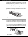
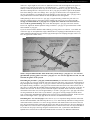
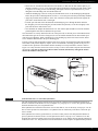
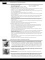
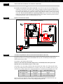
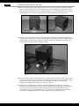
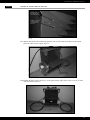
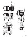
FASTLANE
®
By Endless Pools, Inc.
OWNER’S MANUAL
Wall Mount Installation
Fastlane Swim Unit Installation
®
Section 1
GENERAL OVERVIEW OF A WALL MOUNT FASTLANE
The Wall Mount Fastlane® swimming machine by Endless Pools, Inc. is a hydraulically-powered system that
creates a smooth, adjustable-speed swim current in a conventional pool. The Swim Unit fastens to the wall of
the pool using the bracket provided. Two 1" polyethylene pipes which serve as conduits run under the pool
deck to a remotely located, 5-horsepower, hydraulic Power Unit, as shown in Figure 1.1. It is best if the Power
Unit is within 25' of the Swim Unit to minimize pressure loss. Inside the 1" poly pipe, two 3/8" hydraulic
hoses carrying a non-food grade, biodegradable vegetable oil run between the hydraulic Power Unit and the
Fastlane Swim Unit, thus eliminating the need for electricity poolside. When pumped at high pressure, this
hydraulic fluid creates a swim current by turning the shaft of a submerged stainless steel hydraulic motor in
the Fastlane Swim Unit, which in turn rotates a 16" diameter propeller. The swim current produced is wider
than your body and deeper than your stroke — far superior to currents created by one or more jets. The Power
Unit is activated using a 3-button radio frequency remote control that can turn the unit on and off and adjust
the speed. An optional 6" LED swim pace display is available to monitor your speed. Also, customers often
place our swim mirror on the bottom of the pool to observe their swim stroke.
Fig 1.1
Section 2
CHOOSING A LOCATION FOR YOUR WALL MOUNT FASTLANE
The Fastlane can fit in virtually any swimming pool. For optimal water flow, we recommend that you allow
at least 12 feet between the wall on which the Fastlane is installed and the opposing wall in line with the
Swim Unit. The Fastlane has more than 9 square feet of water intake to eliminate any entrapment hazards.
The water depth where the Fastlane is installed must be at least 35" deep. In addition, the Fastlane must be
installed no closer than 24" from any adjacent wall as shown in Figure 2.1, Minimum Clearance Guidelines.
When choosing a location for your Fastlane, you should also consider the route for the 1" poly pipe to run
back to the Power Unit. The Power Unit needs to sit on a solid, level surface, preferably not on wet ground,
and requires a 30-amp, 220-volt GFCI electric service. For UK and international electrical requirements,
please refer to Section 8. The optional Outdoor Power Unit with Weather Guard may be located outside, but
should not be subject to driving rain. Typically, the Power Unit is located with the other pool equipment and,
if possible, long hydraulic runs should be avoided because of pressure loss. If you wish to have a 1" poly
pipe greater than 25', you must transition from 3/8" hydraulic hoses to 1/2" run hoses with the addition of a
junction box as reviewed in Section 5.
Fig 2.1
Minimum Clearance Guidelines
1
Fastlane Swim Unit Installation
®
Section 3
RECEIVING YOUR WALL MOUNT FASTLANE
The Wall Mount Fastlane is comprised of six (7) parcels. All items will be shipped via UPS Ground.
ITEMS SHIPPED UPS
OPTIONAL EQUIPMENT
Parcel 1: Wall Mount Bracket Assembly
Parcel 2: Two (2) 24' 6" rolls of 1" Polyethylene Pipe
Parcel 3: 5-hp Power Unit with 2 Wireless remote
Controls and Antenna located inside the controller
(heavy Box) Note: If the Outdoor Power Unit
was purchased as an option, the Weather Guard
will come pre-assembled to the Power Unit.
Parcel 4: Five (5) Gallons of hydraulic Fluid
(non-Food Grade Vegetable Oil)
Parcel 5: Fastlane Swim Unit – propulsion housing
Parcel 6: Fastlane Swim Unit – base with pre-installed,
25 feet of hydraulic hoses, grab bar
Parcel 7: Wall mount accessories kit – protective hat channels,
Fastlane lid and hardware kit
• Outdoor Power Unit with Weather Guard
• Floor Mirror
• Swim Pace Display
• Underwater Camera
• hi-Performance 6-hp Power Unit
(in lieu of 5-hp Power Unit)
• Junction Box Kit
(refer to Section 5)
HARDWARE KIT
PACKED InSIDE ThE ACCESSOrIES KIT:
• Thirty (30) 3/4" stainless steel screws for Fastlane Unit Assembly
• Owner’s manual kit with two (2) -8 Female JIC/-6 Male JIC Adapters
Grab Bar hardware Kit includes:
• Six (6) 3/4" stainless steel screws
• Six (6) stainless steel self-locking nuts
Section 4
WALL MOUNT BRACKET AND 1" POLYETHYLENE PIPE INSTALLATION
NOTE: PlEasE rEad iNsTrucTiONs fully bEfOrE bEgiNNiNg brackET iNsTallaTiON.
4.a. gunite/concrete Pool
If the pool being constructed is gunite or concrete, please follow the instructions below.
Parcel 1 includes the Wall Mount Fastlane bracket for concrete or gunite pools. Two (2) 24' 6" rolls of 1" poly pipe
are shipped separately. The standard bracket is comprised of the following components (refer to Photo 4.A.1):
• Two (2) 3/8" threaded 316L stainless steel mounting rods with hardware
• One (1) 3/8" PVC bracket plate
• Two (2) thru-wall Liquid-Tite fittings
• One (1) bonding lug set
3/8" Stainless Steel
Mounting Rod. Firmly secure
these rods to the rebar grid.
Example of 1" poly pipe.
1" poly pipe connects to this
Liquid-Tite fitting and runs
to the hydraulic Power Unit
or junction box.
NOTE: Two (2) 1-1/2" couplings have been included as
an option for use with 1-1/2"
PVC flex pipe as shown in
Photo 4.A.2 (replaces the
Liquid-Tite fittings for use
with the provided 1" poly pipe).
Hang and secure Fastlane
on these SS threaded rods.
Bonding
Lug Set
Wall Mount Fastlane Bracket.
Install this side flush with the
finished pool surface.
Photo 4.A.1
Cover 1" poly pipe end with duct
tape to prevent gunite from clogging the 1" poly pipe.
Bracket Plate
Attach SS bonding wire from
inside the Fastlane housing to
the bonding lug.
2
Fastlane Swim Unit Installation
®
The bracket is to be installed into the pool wall as shown in Figure 4.2 so that the two mounting rods are
1-1/2" above the intended waterline for the pool, which is typically halfway up the skimmer. (The bottom
edge of the Wall Mount Bracket will sit along the pool’s intended waterline.) The rods penetrate 1-1/4" to
1- 1/2" into the finished pool and will be used to hang the Wall Mount Fastlane. These rods must be tied
back to the rebar of the bond beam in the pool and, once encased in concrete, will serve as a suitable hanger.
Additionally, a #8 or larger, solid copper bonding wire must be connected from the pool bonding grid
to the bonding lug located on back of the wall mount bracket.
Fig. 4.2
Level and position the bracket so that the PVC surface of the bracket plate will be flush with the finished
surface of the pool wall as shown in Figures 4.2 and 4.3. The area below the bracket plate should be no
more than 5 degrees less than vertical down to at least 35" below the waterline. The Fastlane is 21" wide.
Consequently, the 21" section of wall where the bracket is located should be straight or near straight. Any
variations from this requirement should be discussed with your design representative. Additionally, it is
imperative that the Fastlane not be installed less than 24" from an adjacent wall to allow for proper water
flow. Please refer back to Figure 2.1, Minimum Clearance Guidelines, for clarification.
Fig. 4.3
Install two (2) complete 1" poly pipes back to the hydraulic Power Unit or junction box. The two (2) 1" poly
pipes may be partially buried and/or covered with concrete. Care should be taken when rounding corners not
to use tighter than 18" radius bends. it is imperative that this 1" poly pipe not be kinked given the close
tolerance of the fittings sliding through later (section 10.4). Do not use couplers with this 1” poly pipe, but
3
Fastlane Swim Unit Installation
®
rather use a single length for each of the two hydraulic hoses that will run through them. The goal is to
provide an easy route for each of the two 3/8" hydraulic hoses — a route free of obstructions and
unlikely to bind. The hydraulic hoses may run on the surface outside the 1" poly pipe, but care must be
taken not to damage them. It is always best to use the 1" poly pipe provided as it protects the hydraulic
hoses from chafing as well as UV damage. The 1" poly pipe is chosen because of its slipperiness and
the ease with which the 3/8" hydraulic hose slides through it. At the same time, this 1" poly pipe can be
easily kinked which will make it difficult to slide the hydraulic hoses through later.
When planning for these two runs of 1" poly pipe, recognize that they penetrate the pool wall 1-1/2"
above the waterline and as a consequence will be flooded if the water level rises to that point. We
strongly recommend that the 1" poly pipe rise to a point above which the water level will never
rise to avoid any potential flooding. This can be done during the 1" poly pipe run or back near the
Power Unit. Tighten the bracket liquid-tite fittings so that the 1" poly pipe is squeezed and water cannot
leak around the 1" poly pipe.
If you are concerned about subsidence and/or kinking, you may prefer to use a heavier 1-1/2" double run
of PVC flex pipe. To accomplish this, simply substitute the two couplings provided with the two (2) liquid-tite fittings threaded into the PVC bracket, apply Teflon Tape to the couplings, and glue in the 1-1/2"
PVC flex pipe (refer to Photo 4.A.2).
3/8" Stainless Steel
Mounting Rod. Firmly secure
these rods to the rebar grid.
These 1-1/2" couplings may
be used if you choose to use
1-1/2" PVC flex pipe rather
than the 1" poly pipe as your
conduit to the Power Unit
and junction box.
Example of 1-1/2"
PVC Flex Pipe
1-1/2" NPT male/slip female
PVC fitting
Hang and secure Fastlane
on these SS threaded rods.
Bonding
Lug Set
Wall Mount Fastlane Bracket.
Install this side flush with the
finished pool surface.
Bracket Plate
Cover PVC end with duct tape
to prevent gunite from clogging
the PVC.
Photo 4.A.2
Attach SS bonding wire from
inside the Fastlane housing to
the bonding lug.
NOTE: The pool builder/installer must decide if they will be using 1" poly pipe or 1-1/2" PVc flex
pipe bEfOrE spraying gunite. Once the 1" poly pipe or 1-1/2" PVc flex pipe has been run, cut, and
trenched, the gunite can be sprayed.
if installing the provided 1" poly pipe (standard installation), the Wall Mount Fastlane ships with two
(2) 24' 6" rolls of 1" poly pipe. From the rear side of the pool, feed each 1" poly pipe into the liquid-tite fittings and tighten the cord grip on the 1" poly pipe so that no water will pass between the 1" poly pipe and
the liquid-tite fitting. Unroll the 1" poly pipe to the location where the Power Unit will be located. The 1"
poly pipe is 6" shorter than the standard length of hydraulic hoses provided. As you run the 1" poly pipe, be
certain it does not kink. To ensure you have sufficient lengths of hydraulic hoses to make the necessary
connections to the Power Unit, cut off approximately 3' of each 1" poly pipe. The 1" poly pipe will need to
exit the ground near the Power Unit. If you find the 1" poly pipe is not long enough to reach the Power
Unit, a junction box and additional hydraulic hoses will need to be ordered and installed. In this case, DO
nOT CUT the length of the 1" poly pipe. refer to Section 5 for additional information.
if installing the 1-1/2" PVc flex pipe, remove the two (2) 1-1/4" liquid-tite fittings from the wall mount
bracket. Thread and adhere with Teflon tape the two (2) 1-1/2" nPT male/slip female PVC fittings into the
wall mount bracket. Unroll the 1-1/2" PVC flex pipe from the wall mount bracket to the Power Unit. The
PVC flex pipe should exit the ground near the Power Unit. Each section of the PVC flex pipe should be no
longer than 21 feet. This will leave enough hydraulic hose to connect to the Power Unit. If you find that 21
feet of the PVC flex pipe is not long enough to reach the Power Unit, a junction box and additional
hydraulic hoses will need to be ordered and installed. refer to Section 5 for additional information.
4
Fastlane Swim Unit Installation
®
4.b. steel/Polymer Panel Pool with a Vinyl liner
If the pool being constructed is steel/polymer panel with a vinyl liner, please follow the instructions below.
remove the star thru-wall fittings and threaded rod pieces with hex coupling nut attachments from the 1/8"thick, grey PVC template. Position the PVC template where the Fastlane will attach to the pool wall and
align the bottom of the template with the expected water level in the pool (which will typically be located
at the centerline of the skimmer) as shown in Figure 4.4. Use duct tape, perhaps wrapped over the top
flange, to temporarily adhere the PVC template to the pool wall. Be certain that the PVC template is level
in the pool. Trace the outline of the star thru-wall fittings and threaded rod hole penetrations that are cut in
the PVC template onto the pool wall. remove the duct-taped PVC template from the pool wall.
Fig. 4.4
Cut (or punch) the openings for the star thru-wall fittings and threaded rod holes. Install the star thru-wall fittings with the holes for the cover at 12, 3, 6 and 9 (clock positions). Choose the appropriate adapters to
thread into the back of the star thru-wall fittings for the type of conduit that will be used for running the
hydraulic hoses from the pool to the Power Unit. Use the provided 1" poly pipe with liquid-tite fittings or a
standard 1-1/2" PVC flex pipe with the provided 1-1/2" couplings. refer to Section 5 for length of 1' poly
pipe or 1-1/2" PVC flex pipe. The threaded rod with hex coupling assembly must now be tightened against
the backside of the pool wall. The 3/8" jam nuts should be fastened on the threaded rod so that half of the
hex coupling is threaded onto the rod and the other half facing the poolside remains empty. Use the sacrificial 3/8" bolts and washers to thread into the hex coupling from the inside of the pool through the hole that
was previously drilled in the wall as shown in Figure 4.5. Tighten the bolts to secure the assembly to the rear
of the pool wall.
Fig. 4.5
5
Fastlane Swim Unit Installation
®
Fig. 4.6
If using rebar in the pool’s collar, tie and bond the bent pieces of threaded rod into the bonded rebar grid.
If no rebar is being used, be sure to bond the threaded rod to the pool’s bonding grid.
Pour the concrete collar around the top flange of the pool securely encasing the threaded rod assemblies
and conduit adapters in place. Even if a bond beam is not being poured for the pool, it is essential for the
operation of the Fastlane that this assembly be securely anchored in concrete. After the concrete has cured,
remove the 3/8" bolts and install the pool liner. Note: Before beginning the liner installation, be sure to
note the orientation of the star thru-wall holes at 12, 3, 6 and 9 (clock positions) as they will be hidden
once the liner is hung. (refer to Figure 4.6.) Make sure there is some water in the bottom of the pool, giving weight to the liner and pulling it tight, before the holes for the star thru-wall fittings and threaded rod
pieces are cut. When the liner is tight enough, cut the holes. Note: Keep the holes for the threaded rod as
small as possible. Attach the faceplate to the star thru-wall fittings, coat the threaded stud and rubber washer with rTV or similar caulk, and thread the stub into the threaded rod assembly. (refer to Figure 4.7.)
Fig. 4.7
4.c. fiberglass Pool installation
If the pool being constructed is fiberglass, please follow the instructions below.
remove the liquid-tite fittings, bonding lug assembly, and threaded rod pieces from the 3/8"-thick, grey
PVC bracket plate which serves as a template. Position the PVC template where the Fastlane will attach to
the pool wall and align the bottom of the PVC template with the expected water level in the pool (which
will typically be located at the centerline of the skimmer). refer to Figure 4.8. Use duct tape, perhaps
wrapped over the top flange, to temporarily adhere the PVC template to the pool wall. Be certain that the
PVC template is level in the pool. Trace the outline of the liquid-tite fittings, bonding lug, and threaded rod
hole penetrations that are cut in the PVC bracket onto the pool wall.
6
Fastlane Swim Unit Installation
®
Fig. 4.8
remove the duct-taped PVC template from the pool wall. Drill the openings for the liquid-tite fittings,
bonding lugs and threaded rod holes. Determine if the provided 1" poly pipe or 1-1/2" PVC flex pipe will
be used as conduit in which to run the hydraulic hoses from the pool to the Power Unit.
if using the provided 1" poly pipe:
• From the rear of the pool, attach the liquid-tite fitting to the fiberglass pool wall and firmly tighten it
to the pool wall. Silicone may be used to get a tight seal.
• Feed the 1" poly pipe into the liquid-tite fittings from the rear of the pool, and tighten the fittings on
the poly pipe (from the rear of the pool) to prevent water from passing between the poly pipe and the
fittings.
• Cut the ends of the 3/8"-thick, grey PVC bracket plate along the score lines. These two ends will act as
washer/bolt heads against the back of the pool wall. Discard the center section as shown in Figure 4.9.
CUT BRACKET BETWEEN NOTCHES
DISCARD MIDDLE SECTION
Fig. 4.9
• Thread the 3/8" threaded rod into the holes in the cut off end pieces, so that once permanently
installed, 1-1/4" to 1-1/2" of threaded rod will penetrate beyond the pool wall surface. refer to Figure
4.10. To help prevent cross threading, thoroughly clean the exposed end of the threaded rods of any
excess fiberglass before threading nuts onto the threaded rods.
• Attach the bonding lug to the rear of the pool and thread the screw for the bonding lug through the
hole in the pool wall. The bonding lug screw should penetrate at least a 1/2" into the pool wall when
permanently installed. A #8 or larger, solid copper bonding wire must be connected from the pool
bonding grid to the bonding lug located on the back of the wall mount bracket
• Apply the provided silicone adhesive to the side of the PVC bracket plate that will mate against the
pool wall to ensure that the seal is watertight.
• Feed the poolside ends of the threaded rods through the holes drilled in the fiberglass pool wall, and
using the provided washers and jam nuts, secure the rod tightly to the pool wall. Leave nuts and washers
attached until silicone cures.
if using the 1-1/2" PVc flex pipe:
• The bracket will nOT be cut into three pieces.
• Thread and adhere with Teflon tape the provided couplings into the threaded holes in the 3/8"-thick,
grey PVC bracket.
• Glue the necessary length of PVC flex pipe to the couplings. refer to Section 5.
7
Fastlane Swim Unit Installation
®
• Thread the 3/8" threaded rod into the holes in the bracket, so that once the PVC bracket plate is permanently installed, 1-1/4" to 1-1/2" of threaded rod will penetrate beyond the pool wall surface. refer
to Figure 4.10. To help prevent cross threading, thoroughly clean the exposed thread of any excess
fiberglass before threading nuts onto the threaded rods.
• Attach the bonding lug to the rear of the pool, and thread the screw for the bonding lug through the
hole in the pool wall. It should penetrate at least a 1/2" into the pool wall when permanently installed.
• Apply the provided silicone adhesive to the side of the PVC bracket plate that will mate against the
pool wall to ensure that the seal is watertight.
• Feed the pool side ends of the threaded rods and bonding lug screw through the holes drilled in
the fiberglass pool wall, and using the provided washers and jam nuts, secure the rod tightly to the
pool wall and leave until silicone cures.
• Once installed, the adapter threaded into the 3/8" PVC bracket plate should be seen from inside the
pool through the holes that are drilled in the pool wall.
Once the bracket is securely attached to the rear of the pool wall, tie the bent pieces of threaded rod into
the bonded rebar grid. If no rebar is being used, be sure to bond the threaded rod to other metallic pool
items and pool equipment. Attach a bonding wire to the bonding lug on the back of the bracket, and be
sure to bond the threaded rod to the pool’s bonding grid.
Pour the concrete collar around the top flange of the pool, securely encasing the threaded rod assemblies
and conduit (with possible adapters) in place. Even if a bond beam is not being poured for the pool, it is
essential for the operation of the Fastlane that this assembly be securely anchored in concrete. refer to
Figure 4.10. Only when the concrete has cured is it okay to remove the washers and jam nuts and install
the Fastlane. Note: do not throw away these washers and nuts, because they will again be used to
anchor the fastlane to the pool wall.
Fig. 4.10
Section 5
JUNCTION BOX AND 1/2" RUN HOSES (OPTIONAL)
The wall mount bracket must be attached on the pool wall as explained in the installation instructions in
Section 4. Attached to this bracket are two (2) lengths of 1" poly pipe or 1-1/2" PVC flex pipe that run back
under the deck and carry two (2) hydraulic hoses.
If the hydraulic hose runs back to the Power Unit are less than 25', it is not necessary to step up to 1/2" run
hose to reduce pressure loss. Instead, the 3/8" hydraulic hose can run directly to the Power Unit in the protective conduit.
If the hydraulic hose runs are greater than 25', in order to reduce pressure loss and potential reduction in
speed, a junction box must be used. It is at the junction box where a step up to 1/2" run hose occurs. The
hydraulic hose from the Fastlane Swim Unit to the junction box is 3/8" and the run hose from the junction box
to the Power Unit is 1/2". The junction box must be located at the elevation equal to or higher than the pool deck.
8
Fastlane Swim Unit Installation
®
Section 5
JUNCTION BOX AND 1/2" RUN HOSES (OPTIONAL)
Junction Box Kit (optional) includes:
• One (1) junction box with feet
• Two (2) 1-1/2" liquid-tite fittings
• Four (4) 1-1/2" nPT male/slip female PVC fittings
• Six (6) 1-1/2" locknuts
• roll of anti-corrosion tape
If installing the optional junction box with the 1" poly pipe:
• The Fastlane ships with two (2) 24' 6" rolls of 1" poly pipe. Do nOT cut down the length of this 1" poly pipe.
• Install the two (2) 1-1/2" liquid-tite fittings in the same side of the junction box.
• Feed the 1" poly pipe into the liquid-tite fittings and tighten the fittings so that no water will pass between
the 1" poly pipe and the fittings.
• To get from the junction box to the Power Unit, run 1-1/2" PVC flex pipe.
• roll two (2) lengths of PVC flex pipe from the junction box to the Power Unit. The PVC flex pipe should
exit near the Power Unit.
• Measure the length of PVC flex pipe. Your 1/2" run hose will need to be AT LEAST 4 feet longer than the
length of the PVC flex pipe. Order your 1/2" run hoses at this time by calling our Customer Service
Department at 800-910-2714.
• Glue the 1-1/2" nPT male/slip female fittings on the end of the PVC flex pipe that will connect to the junction box. Secure the fittings to the junction box with the provided lock nuts. The PVC flex pipe can be
buried in a trench.
• Adapters to connect the 1/2" run hoses to the 3/8" hoses attached to the Fastlane have been provided. They
can be found in the 1/2" run hose box.
• If desired, the junction box can be anchored by attaching the feet included with the kit.
If installing the optional junction box with the 1-1/2" PVC flex pipe:
• The 1-1/2" PVC flex pipe will need to be cut to 24' 6" from the wall mount bracket to the junction box.
• Glue the 1-1/2" nPT male/slip female fittings on the end of the PVC flex pipe that will connect to the
junction box. Secure the fittings to the junction box with the provided lock nuts.
• To get from the junction box to the Power Unit, run 1-1/2" PVC flex pipe.
• Unroll the two (2) lengths of PVC flex pipe from the junction box to the Power Unit. The PVC flex pipe
should exit the ground next to the Power Unit.
• Measure the length of PVC flex pipe. Your 1/2" run hoses will need to be AT LEAST 4 feet longer then the
length of the PVC flex pipe. Order your 1/2" run hoses at this time by calling our Customer Service
Department at 800-910-2714.
• Glue the 1-1/2" nPT male/slip female fittings on the end of the PVC flex pipe that will connect to the junction box. Secure the fittings to the junction box with the provided lock nuts. The PVC flex pipe can be
buried in a trench.
• Adapters to connect the 1/2" run hoses to the 3/8" hoses attached to the Fastlane have been provided. They
can be found in the run hose box.
• If desired, the junction box can be anchored by attaching the feet included with the kit.
Section 6
INSTALLATION AND TESTING OF THE HYDRAULIC POWER UNIT
6.1 PLACEMEnT COnSIDErATIOnS: The Power Unit should be placed on a flat, level surface, prefer-
ably not on wet ground. If placing outside, it is recommended the Outdoor Power Unit with Weather
Guard be purchased (see Fig 6.1), but should not be subject to driving rain. If placing indoors and at a
level below the pool deck, such as a basement, a floor drain is mandatory to accommodate the unlikely
event of a hole developing in the hydraulic hose creating a siphon. Whether placed indoors or out, this
is an air-cooled unit and must have ample ventilation. Therefore, a minimum of 12" air space must be
provided on all sides of the Power Unit motor. In addition, while frequent access is not required, it is
imperative the Power Unit be accessible.
6.1
6.2 Carefully remove the Power Unit from the packaging. Note: The Power Unit is very heavy. To remove
Fill Cap
Antenna
Low
Pressure
the Power Unit open box top flaps, lay box on its side, open box bottom flaps, and slide the Power Unit
out of the box sideways on the bottom foam.
6.3 Place the Power Unit in the selected position and verify that the hose connections are pointed in the
direction you desire.
Proportional
Relief Valve
6.3
9
High Pressure
6.4 have an electrician make the electrical connections using the whip provided. Make this connection by
hard wiring to a disconnect or using an appropriate lock tight plug and socket. The Power Unit requires
single-phase 220-volt, 30-amp GFCI-protected power. Verify proper incoming voltage and wiring.
refer to Section 7, “Power Unit Electrical Wiring.” note: The white wire will not be usedin this application (no neutral is required). For UK and international electrical requirements, please refer to Section
Fastlane Swim Unit Installation
®
Section 6
INSTALLATION AND TESTING OF THE HYDRAULIC POWER UNIT
8.
6.5 Turn the circuit breaker for the Power unit Off. Secure the test caps to the low and high pressure
connections on the Power Unit. remove the oil filter by lifting it out of the fill opening. Fill the Power
Unit with the approximately four (4) gallons of hydraulic fluid provided. (The fill cap is at the low pressure fitting.) Once filled with oil, replace the oil filter and cap and press firmly to ensure proper seating
of the filter. do not run unit without test caps being installed. Turn circuit breaker on. Install antenna
and briefly test the Power Unit operation using the remote control. Note: Continued operation with the
test plugs installed may result in overheating the Power Unit.
Section 7
POWER UNIT ELECTRICAL WIRING
Power Unit Electrical Wiring
Section 8
ELECTRICAL REQUIREMENTS FOR UK AND OTHER INTERNATIONAL COUNTRIES
The unique design of the Fastlane facilitates sales to UK and international customers. The Fastlane is
shipped in kit form for easy assembly and installation into any new conventional pool following the
detailed instructions provided.
The Fastlane is ETL marked and CE listed.
The Power unit circuit must be rcd (gfi) protected. The Mcb (breaker) that operates the
hydraulic Power unit should be Ç-type or motor-rated.
United States wire color-coding is different than international color-coding. The following chart identifies the color-coding used in the United States as it relates to the wire type. In addition, the wires of the
controller have a short, colored sleeve wrapped around them to conform to the international color codes.
us Wiring color
Wire Type
Wire sleeve color
Black, red, or Blue
Live or hot
Brown
White
neutral
Blue
Green
Ground
Yellow with Green Stripe
Should you have any questions, please call the Customer Service Department at 0800-028-1056 (UK
Only), 610-497-4538 (Direct), or email us at [email protected].
10
Fastlane Swim Unit Installation
®
Section 9
ASSEMBLY OF THE WALL MOUNT SWIM UNIT
9.1 Carefully unpack the swim unit from its boxes. Make sure to remove any hardware packs from
the boxes as well. The packaging can be collapsed and used as a protective surface upon which to
assemble the Fastlane. The foam packing material can be used to wedge under the base to prevent
it from tipping over.
9.2 Take care when handling or working with any of the stainless steel components of the swim unit.
The ends can be sharp. The first step is to remove the two circular end caps from each side of the
cylindrical base. There are 3 arced cover strips around the perimeter of each end cap. Unthread the
nine screws that secure the cover strips (3 screws per cover strip). Carefully set each end cap aside
(Fig 9.1).
Cylindrical base with 25'
hydraulic hoses attached
Circular End Cap
Arched Cover Strip
Fig. 9.1
9.3 Uncoil the two lengths of hydraulic hose that are attached to the cylindrical base. Make sure that the
hoses are seated into their respective notches in the backside of the base (Fig 9.2).
Notches in the base
for the hoses
Fig. 9.2
9.7
11
Fastlane Maintenance
®
Section 9
ASSEMBLY OF THE WALL MOUNT SWIM UNIT
9.4 remove the throat from the upper housing. There are two screws on each side of the throat. Pull the
throat off of the housing and set it aside. Pull the vertical water-conditioning grill up and out of the
housing. Pull the horizontal grill out of its track and remove from the housing. Make sure to remove
and discard the wood 2x4 spacer from the bottom of the housing before proceeding (Fig 9.3).
Throat
Vertical Water
Conditioning Grill
Horizontal Water
Conditioning Grill
2x4 Spacer
Fig. 9.3
9.5 Carefully remove the protective film encasing the upper housing. Place the upper housing into the
opening of the cylindrical base (Fig 9.4). The hydraulic hoses connected to the base should be aligned
with the back of the upper housing. Make sure that the stainless steel bonding wire attached to the
motor mount is positioned inside of the upper housing.
1 screw attaching housing
to the reinforcing support
3 screws attaching
housing to base
Fig. 9.4
9.6 Use the provided stainless steel machine screws to attach the upper housing to the base. There will be
4 screws per side (total of 8). On each side of the housing, there will be 3 screws securing the upper
housing to PVC motor mount support and 1 screw attaching the stainless steel reinforcing
support to the housing just above the 3 previous screws (Fig 9.4).
9.7 Carefully lay the Fastlane onto its front face. run the hydraulic hoses up the back of the upper
housing. The two hat channels will be placed over the hydraulic hoses. Make sure that the mounting
hole in the end of the hat channel is facing up and that the bottom of the hat channel has been
inserted into the notch in the cylindrical base. Use the provided 3/4" machine screws to attach the
hat channels to the upper housing. There will be eight screws per hat channel (Fig 9.5).
12
Fastlane Swim Unit Installation
®
Section 9
ASSEMBLY OF THE WALL MOUNT SWIM UNIT
Hat Channel
Mounting Hole
Fig. 9.5
9.8 Pull any excess hose out of the hat channel. Attach the two hoses to the top of the upper housing.
There are 2 green hose clamps attached to the top of the housing. The screws that are securing the
clamps to the housing will have to be removed in order to secure the hoses to the clamps. The hoses
should cross over one another prior to attaching to the housing (Fig 9.6).
Fig. 9.6
9.9 run the stainless steel wire attached to the motor mount up and through the 3rd turning vane (from
the bottom) inside the upper housing. The wire should be on the left side of the housing as you are
facing the unit (Fig 9.7).
9.10 Install the stainless steel grab bar to the upper housing using the provided machine screws and lock
nuts. Make sure to place the stainless steel wire (from the motor mount in the base) around the
bottom screw on the left side before tightening down on the nut. Place the second stainless steel
wire (that exits the top rear of the upper housing) around another screw before tightening down
on the nut (Fig 9.7).
13
Fastlane Maintenance
®
Section 9
ASSEMBLY OF THE WALL MOUNT SWIM UNIT
Stainless steel wire
that exits the top
rear of the housing
Stainless steel wire
coming from the
motor mount in
the base
Fig. 9.7
9.11 Slide the horizontal water-conditioning grill back into its track inside the housing. The horizontal
grill is the wider of the two grills (Fig 9.8).
Horizontal Water
Conditioning Grill
Fig. 9.8
9.12 reattach the throat (removed in step 3) to the upper housing. Again, there will be 2 screws on either
side of the throat (total of 4).
Throat
Fig. 9.9
14
Fastlane Swim Unit Installation
®
Section 9
ASSEMBLY OF THE WALL MOUNT SWIM UNIT
9.13 Slide the vertical water-conditioning grill back down into the housing (Fig 9.10).
Fig. 9.10
9.14 re-install the circular end caps. Make sure that the “smooth” surface of the end caps are facing out.
Align the end caps to the internal PVC supports so that the holes in the internal supports are aligned
with holes in the end caps. Position the arced cover strips over the end caps, making sure to align
the hole in the arced cover strips with the holes in the stainless end caps and the internal PVC supports. Install the nine screws (3 per cover strip) that were removed in step 2. repeat for the remaining end cap (Fig 9.11).
Circular End Cap
Arched Cover Strip
Fig. 9.11
9.15 Once the Fastlane is installed in the pool, place the housing lid onto the housing and use the
provided screws to attach. There will be three screws per side, for a total of six (Fig 9.12).
Housing Lid
Fig. 9.12
15
Fastlane Maintenance
®
Section 10
INSTALLATION OF YOUR FASTLANE
10.1 Fill the pool up with water. The water line should be halfway up the skimmer along the bottom of the
wall mount bracket and 1-1/2" below the two (2) mounting rods.
10.2 Using two people, one on each side of the Fastlane Swim Unit, place one hand on the side of the grab rail
and the other hand on the back of the Swim Unit. Carefully, lift the Swim Unit and gently lower it into
the pool. NOTE: Be watchful not to scratch the Swim Unit on the stainless steel, threaded rods protruding from the wall mount bracket.
10.3 hang the hydraulic hoses down over the front of the Fastlane Swim Unit. Match the holes on the top of
the “hat” channel of the housing with the stainless steel, threaded rods in the wall mount bracket. Secure
tightly with the two (2) 3/8" stainless steel flat washers , the two (2) lock washers, and the two (2) nuts
provided (one for each rod) as shown in Figure 10.1. attach the bonding wire to the bonding lug set
located on the wall mount bracket to bond the entire swim unit to the pool.
10.4 Once the Fastlane is secured to the wall mount bracket, feed one hydraulic hose through one of the 1"
poly pipes until all of the hose is through. repeat for the second hydraulic hose. Install the Fastlane lid
(see Section 9.15).
10.5 remove the test plug(s) from the low and high-pressure connections on the Power Unit. Connect the
hydraulic hoses to the Power Unit. The low-pressure hose has red tape on the end. Connect the low-pressure hose to the port at the fill cap and the high-pressure hose to the port with the proportional relief
valve. (refer to Photo 6.3 on page 9)
10.6 You are now ready to start up your Fastlane. Take the remote control used during the testing process in
Section 6 and press and hold the ON/Off button turning on the Fastlane and producing a current.
The Fastlane features 52 incremental steps in speed. Press and release the fasTEr button to increase the
speed of the current one step at a time. Alternatively, press and continue to hold the fasTEr button to
ramp up the speed until the button is released or the maximum speed is achieved. reduce the speed in the
same manner using the slOWEr button.
Turn off the Fastlane by again pressing the ON/Off button.
The Power Unit remote control is equipped with an automatic timer shutting off the system 30 minutes
after receiving its last command. Because the Fastlane “remembers” the speed at which it was turned off,
it will return to that same pace when it is turned back on.
Fig 10.1
16
Fastlane Swim Unit Installation
®
Section 11
GENERAL INFORMATION
Once installed, the Fastlane will provide years of exercise and fun with minimal maintenance. Clean the
intake grills of leaves as needed and wipe down the stainless steel cylindrical base and grab rail with warm
water, a Scotch Brite pad, and brisk rubbing. Clean the acrylic housing with any typical non-ammonia, nonabrasive kitchen cleanser. Periodically, check all electrical and ground wire connections and test the GFCI
circuit breaker for proper function.
it is important for the long-term operation of your fastlane that your pool water be properly
balanced and in accordance with normal pool industry standards. in addition, it is imperative that
the fastlane be bonded to the pool bonding grid.
Endless Pools, Inc. is an industry leader in customer service, should you ever have questions or concerns
about your Fastlane, please contact our Customer Service Department at 800-910-2714.
Section 12
SCHEDULED MAINTENANCE
12.1 Hydraulic Motor and fluid Maintenance. We recommend the hydraulic motor, which is located in your
swim unit and submerged underwater, be replaced after four years of usage. We also recommend changing
the non-food grade, biodegradable vegetable oil and filter in the Power Unit after every 500 hours of use.
12.2 grill cleaning. Should you perceive a reduction in speed of your Fastlane, it may be caused by a reduction
in water flow due to a blockage of the inlet assembly of the cylindrical base. Because the underside of your
Fastlane will be sucking in water, it may occasionally become necessary to clean the grill of any debris or
leaves that may have been in your pool when the Fastlane was in operation. With the Fastlane unit turned
off, this is very easy to accomplish while in the pool.
12.3 cold Weather Maintenance. At the end of the swimming season, it is recommended the Fastlane Swim
Unit be removed from the swimming pool and winterized. A winterizing kit for the Fastlane can
be purchased from Customer Service. For specific instructions, please contact our Customer Service
Department at 800-910-2714.
12.4 use of salt-chlorine generators. Placing a Fastlane in a pool sanitized using a salt-chlorine generator creates increased risk of a hydraulic system failure and oil leaks. Any Fastlane placed in this type of environment must be properly bonded, and water chemistry must be closely monitored. As stated in our warranty,
ph levels must be maintained between 7.4 and 7.8, total alkalinity between 80 and 120 ppm, salt chlorine
levels below 4000 ppm, and total dissolved solids below 7000 ppm. Failure to properly bond the Fastlane
or maintain proper water chemistry will void the warranty.
If you are using a salt-chlorine generator, please complete the following tasks:
• remove and inspect your Fastlane unit annually. Once removed, rinse the Fastlane with fresh water before
storing for the off-season.
• replace the underwater hydraulic motor and submersible hoses every two years.
• Ensure that the fluid level in your power unit is no more than one cup above the float level switch. This
simple procedure ensures that any oil leak is minimized
17
Fastlane Maintenance
®
Section 13
FASTLANE® BY ENDLESS POOLS, INC. WARRANTY
Endless Pools, Inc. warrants to the original purchaser of Fastlane manufactured by us to be free from
defects in material and workmanship under normal use for two years from purchase. OUr OBLIGATIOn UnDEr ThIS WArrAnTY ShALL BE LIMITED TO ThE rEPAIr Or EXChAnGE (AT
OUr OPTIOn) OF AnY PArT Or PArTS WhICh MAY ThUS PrOVE DEFECTIVE UnDEr
nOrMAL USE WIThIn TWO YEArS FrOM DATE OF PUrChASE BY ThE OrIGInAL
PUrChASEr, AnD WhICh OUr EXAMInATIOn ShALL DISCLOSE TO OUr SATISFACTIOn
TO BE ThUS DEFECTIVE. ThIS WArrAnTY IS EXPrESSLY In LIEU OF ALL OThEr
WArrAnTIES EXPrESSED Or IMPLIED InCLUDInG ThE WArrAnTIES OF MErChAnTABILITY AnD FITnESS FOr USE AnD OF ALL OThEr OBLIGATIOnS Or
LIABILITIES FOr ALL DAMAGES DIrECT Or COnSEQUEnTIAL TO PErSOn, PrOPErTY,
Or BUSInESS WhEThEr Or nOT OCCASIOnED BY OUr nEGLIGEnCE, AnD WE
nEIThEr ASSUME FOr US AnY OThEr LIABILITY In COnnECTIOn WITh ThE SALE OF
ThIS FASTLAnE. ThIS WArrAnTY ShALL nOT APPLY TO ThIS FASTLAnE Or AnY PArT
ThErEOF, WhICh hAS BEEn SUBJECT TO ACCIDEnT, nEGLIGEnCE, FrEEZInG,
IMPrOPEr InSTALLATIOn, ALTErATIOn, ABUSE, Or MISUSE. ThIS InCLUDES, BUT
IS nOT LIMITED, TO FLOW rESTrICTIOnS Or OBSTrUCTIOnS On ALL WATEr AnD
hYDrAULIC SYSTEMS AnD nOT PrOPErLY BOnDInG Or MAInTAInInG PrOPEr
WATEr ChEMISTrY (ph level must be maintained between 7.4 and 7.8 and total alkalinity between
80 and 120 ppm. The total dissolved solids (TDS) must be no greater than 3,000 ppm). POOLS USInG
SALT ChLOrInE GEnErATOrS rEQUIrE ADDITIOnAL MAInTEnAnCE. MAInTAIn A
SALT COnTEnT BELOW 4,000 ppm AnD TDS WITh SALT BELOW 7,000 ppm. rEMOVE ThE
FASTLAnE AnnUALLY, rInSE WITh FrESh WATEr AnD InSPECT UnDErWATEr
hYDrAULIC MOTOr AnD hOSE FITTInGS. SET ThE hYDrAULIC FLUID LEVEL TO
OnE CUP OVEr ThE FLOAT LEVEL SWITCh (COnTACT CUSTOMEr SErVICE FOr
DETAILED InSTrUCTIOnS).
ThE TErM “OrIGInAL PUrChASEr”, AS USED In ThIS WArrAnTY, ShALL BE DEEMED
TO MEAn ThAT PErSOn FOr WhOM ThE FASTLAnE WAS OrIGInALLY InSTALLED.
ThIS WArrAnTY ShALL APPLY OnLY WIThIn ThE BOUnDArIES OF ThE COnTInEnTAL
UnITED STATES.
WE DO nOT WArrAnT ThIS MAChInE TO MEET ThE rEQUIrEMEnTS OF AnY SAFETY
CODE OF AnY STATE, MUnICIPALITY, Or OThEr JUrISDICTIOn. PUrChASEr ASSUMES
ALL rISK AnD LIABILITY WhATSOEVEr rESULTInG FrOM ThE USE ThErEOF, InCLUDInG DAMAGE Or STAInInG TO AnY POOL Or POOL DECK, WhEThEr USED SInGLY Or
In COMBInATIOn WITh OThEr MAChInES Or APPArATUS.
In order to claim under this warranty, original purchaser must promptly notify our Customer Service
Department in writing of the existence of the claim and then follow our written instructions regarding
the procedures for remedying the defect. Endless Pools, Inc. shall not be responsible for cartage,
transportation, removal, and/or re-installation labor or any other such costs relating to performance
of the warranty.
All orders are FOB Aston, PA. We will nOT be liable for any costs or losses due to changes in
shipping schedules, or delivery times. It is the responsibility of the Customer to supply safe and
proper site preparation, installation and operation for all Endless Pool Swimming Machines. This
includes, but is not limited to, adequate drainage at any pool and/or equipment site, to control
humidity, to post necessary safety signage and to ensure safe and proper use of all Endless Pool
Swimming Machines. Customer shall be responsible for any and all building permits, fees, licenses,
and authorizations necessary to comply with local building codes or requirements. Customer takes
all responsibility for site preparation including, but not limited to, any slab or foundation. Any
Endless Pools product installed above grade must be placed on a properly engineered structure,
which is the responsibility of the customer.
In the event any portion of this warranty shall be deemed unenforceable by a court of law, the remainder of this warranty shall remain in full force and effect as if the voided portion were never included.
Endless Pools, inc. 1601 dutton Mill rd, aston, Pa 19014 800-910-2714
18
FLWM 11-10
© 2011 Endless Pools, Inc.