1
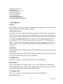
PCM-7130
Intel StrongARM SA1110-based
Single Board Computer with
Windows CE.NET
Users Manual
Copyright
This document is copyrighted, © 2002. All rights are reserved. The original manufacturer reserves the right to make improvements to the products
described in this manual at any time without notice.
No part of this manual may be reproduced, copied, translated or transmitted in any form or by any means without the prior written permission of
the original manufacturer. Information provided in this manual is
intended to be accurate and reliable. However, the original manufacturer
assumes no responsibility for its use, nor for any infringements upon the
rights of third parties that may result from such use.
Acknowledgements
IBM, PC/AT, PS/2 and VGA are trademarks of International Business
Machines Corporation.
Intel and StrongARM are trademarks of Intel Corporation.
Microsoft Windows® CE.NET is a registered trademark of Microsoft
Corp.
All other product names or trademarks are properties of their respective
owners.
For more information on this and other Advantech products, please visit
our websites at:
http://www.advantech.com
For technical support and service, please visit our support website at:
http://support.advantech.com
This manual is for the PCM-7130.
Part No. 200671300
1st Edition: August, 2002
PCM-7130 User’s Manual
ii
Packing List
Before you begin installing your card, please make sure that the following
materials have been shipped:
• Support CD
• Windows CE end user license agreement
• USB client ActiveSync cable
• Y-shaped adapter for PS/2 mouse and keyboard
• Audio cable
• RS-232 and RS-485 combo cable
If any of these items are missing or damaged, contact your distributor or
sales representative immediately.
Additional Information and Assistance
Step 1. Visit the Advantech web site at www.advantech.com/risc where
you can find the latest information about the product.
Step 2. Contact your distributor, sales representative, or Advantech's customer service center for technical support if you need additional
assistance. Please have the following information ready before
you call:
• Product name and serial number
• Description of your peripheral attachments
• Description of your software (operating system, version, application
software, etc.)
• A complete description of the problem
• The exact wording of any error messages
iii
FCC Class A
This equipment has been tested and found to comply with the limits for a
Class A digital device, pursuant to Part 15 of the FCC Rules. These limits
are designed to provide reasonable protection against harmful interference when the equipment is operated in a residential environment. This
equipment generates, uses and can radiate radio frequency energy. If not
installed and used in accordance with this user's manual, it may cause
harmful interference to radio communications. Note that even when this
equipment is installed and used in accordance with this user's manual,
there is still no guarantee that interference will not occur. If this equipment is believed to be causing harmful interference to radio or television
reception, this can be determined by turning the equipment on and off. If
interference is occurring, the user is encouraged to try to correct the interference by one or more of the following measures:
• Reorient or relocate the receiving antenna
• Increase the separation between the equipment and the receiver
• Connect the equipment to a power outlet on a circuit different from that
to which the receiver is connected
• Consult the dealer or an experienced radio/TV technician for help
Warning!
Any changes or modifications made to the
equipment which are not expressly approved by
the relevant standards authority could void your
authority to operate the equipment.
PCM-7130 User’s Manual
iv
Warning!
Input voltage rated 12 V ~ 24 Vdc, 0.3 A max
(LCD excluded)
Packing: please carry the unit with both hands,
handle with care
Our European representative:
Advantech Europe GmbH
Kolberger Straße 7
D-40599 Düsseldorf, Germany
Tel: 49-211-97477350
Fax: 49-211-97477300
Maintenance: to properly maintain and clean
the surfaces, use only approved products or
clean with a dry applicator
v
Safety Instructions
1. Read these safety instructions carefully.
2. Keep this User's Manual for later reference.
3. Disconnect this equipment from any AC outlet before cleaning. Use a damp
cloth. Do not use liquid or spray detergents for cleaning.
4. For plug-in equipment, the power outlet socket must be located near the
equipment and must be easily accessible.
5. Keep this equipment away from humidity.
6. Put this equipment on a reliable surface during installation. Dropping it or letting it fall may cause damage.
7. The openings on the enclosure are for air convection. Protect the equipment
from overheating. DO NOT COVER THE OPENINGS.
8. Make sure the voltage of the power source is correct before connecting the
equipment to the power outlet.
9. Position the power cord so that people cannot step on it. Do not place anything
over the power cord.
10. All cautions and warnings on the equipment should be noted.
11. If the equipment is not used for a long time, disconnect it from the power
source to avoid damage by transient overvoltage.
12. Never pour any liquid into an opening. This may cause fire or electrical shock.
13. Never open the equipment. For safety reasons, the equipment should be
opened only by qualified service personnel.
14. If one of the following situations arises, get the equipment checked by service
personnel:
a. The power cord or plug is damaged.
b. Liquid has penetrated into the equipment.
c. The equipment has been exposed to moisture.
d. The equipment does not work well, or you cannot get it to work according
to the user's manual.
e. The equipment has been dropped and damaged.
f. The equipment has obvious signs of breakage.
15. DO NOT LEAVE THIS EQUIPMENT IN AN ENVIRONMENT WHERE
THE STORAGE TEMPERATURE MAY GO BELOW -20° C (-4° F) OR
ABOVE 60° C (140° F). THIS COULD DAMAGE THE EQUIPMENT. THE
EQUIPMENT SHOULD BE IN A CONTROLLED ENVIRONMENT.
16. CAUTION: DANGER OF EXPLOSION IF BATTERY IS INCORRECTLY
REPLACED.REPLACE ONLY WITH THE SAME OR EQUIVALENT
TYPE RECOMMENDED BY THE MANUFACTURER, DISCARD USED
BATTERIES ACCORDING TO THE MANUFACTURER'S INSTRUCTIONS.
The sound pressure level at the operator's position according to IEC 704-1:1982 is
no more than 70 dB (A).
DISCLAIMER: This set of instructions is given according to IEC 704-1. Advantech disclaims all responsibility for the accuracy of any statements contained
herein.
PCM-7130 User’s Manual
vi
Wichtige Sicherheishinweise
1. Bitte lesen sie Sich diese Hinweise sorgfältig durch.
2. Heben Sie diese Anleitung für den späteren Gebrauch auf.
3. Vor jedem Reinigen ist das Gerät vom Stromnetz zu trennen. Verwenden Sie
Keine Flüssig-oder Aerosolreiniger. Am besten dient ein angefeuchtetes Tuch
zur Reinigung.
4. Die NetzanschluBsteckdose soll nahe dem Gerät angebracht und leicht
zugänglich sein.
5. Das Gerät ist vor Feuchtigkeit zu schützen.
6. Bei der Aufstellung des Gerätes ist auf sicheren Stand zu achten. Ein Kippen
oder Fallen könnte Verletzungen hervorrufen.
7. Die Belüftungsöffnungen dienen zur Luftzirkulation die das Gerät vor überhitzung schützt. Sorgen Sie dafür, daB diese Öffnungen nicht abgedeckt werden.
8. Beachten Sie beim. AnschluB an das Stromnetz die AnschluBwerte.
9. Verlegen Sie die NetzanschluBleitung so, daB niemand darüber fallen kann.
Es sollte auch nichts auf der Leitung abgestellt werden.
10. Alle Hinweise und Warnungen die sich am Geräten befinden sind zu
beachten.
11. Wird das Gerät über einen längeren Zeitraum nicht benutzt, sollten Sie es vom
Stromnetz trennen. Somit wird im Falle einer Überspannung eine Beschädigung vermieden.
12. Durch die Lüftungsöffnungen dürfen niemals Gegenstände oder Flüssigkeiten
in das Gerät gelangen. Dies könnte einen Brand bzw. elektrischen Schlag auslösen.
13. Öffnen Sie niemals das Gerät. Das Gerät darf aus Gründen der elektrischen
Sicherheit nur von authorisiertem Servicepersonal geöffnet werden.
14. Wenn folgende Situationen auftreten ist das Gerät vom Stromnetz zu trennen
und von einer qualifizierten Servicestelle zu überprüfen:
a - Netzkabel oder Netzstecker sind beschädigt.
b - Flüssigkeit ist in das Gerät eingedrungen.
c - Das Gerät war Feuchtigkeit ausgesetzt.
d - Wenn das Gerät nicht der Bedienungsanleitung entsprechend funktioniert
oder Sie mit Hilfe dieser Anleitung keine Verbesserung erzielen.
e - Das Gerät ist gefallen und/oder das Gehäuse ist beschädigt.
f - Wenn das Gerät deutliche Anzeichen eines Defektes aufweist.
15. VOSICHT: Explisionsgefahr bei unsachgemaben Austausch der Batterie.Ersatz nur durch densellben order einem vom Hersteller empfohlenemahnlichen Typ. Entsorgung gebrauchter Batterien navh Angaben des
Herstellers.
Der arbeitsplatzbezogene Schalldruckpegel nach DIN 45 635 Teil 1000
beträgt 70dB(A) oder weiger.
DISCLAIMER: This set of instructions is given according to IEC704-1.
Advantech disclaims all responsibility for the accuracy of any statements
contained herein.
vii
PCM-7130 User’s Manual
viii
Contents
Chapter
1 General Information ........................................2
1.1
1.2
1.3
1.4
Introduction ....................................................................... 2
Features ............................................................................. 3
Specifications .................................................................... 4
Dimensions and Board Layout.......................................... 6
Figure 1.1:Component Side ............................................ 6
Figure 1.2:Component side............................................. 7
Figure 1.3:Solder side ..................................................... 7
Chapter
2 Installation ......................................................10
2.1
Connectors....................................................................... 10
Figure 2.1:Component side of the PCM-7130.............. 10
Table 2.1:Connectors on the PCM-7130 ...................... 11
Figure 2.2:Solder side of the PCM-7130 ...................... 11
Table 2.2:Miscellaneous ............................................... 12
2.2
Pin Assignments.............................................................. 13
Table 2.3:COM1 RS-232 serial port (CN1).................. 13
Table 2.4:COM2 RS-232 & COM3 RS-485 (JP2) ....... 14
Table 2.5:10Base-T Ethernet port (CN2) ..................... 15
Table 2.6:PS/2 keyboard/mouse connector (CN13) ..... 15
Table 2.7:USB client port (J2)...................................... 16
Table 2.8:USB host port (CN14) .................................. 16
Table 2.9:CRT display port VGA-out (CN9) ............... 17
Table 2.10:TV-out (CN8) ............................................. 17
Table 2.11:40-pin LCD connector (CN3)..................... 18
Table 2.12:LCD signal mapping................................... 19
Table 2.13:20-pin LVDS connector (J1) ...................... 20
Table 2.14:LCD inverter connector (CN4)................... 20
Table 2.15:4-wire touchscreen connector..................... 20
Table 2.16:DC power connector (CN6)........................ 21
Table 2.17:Audio connector (JP1) ................................ 21
Table 2.18:Battery signal control connector (CN5)...... 21
Table 2.19:System wake-up connector (CN10)............ 22
Table 2.20:System reset connector (CN7).................... 22
Table 2.21:DI/DO connector (JP6)............................... 22
Table 2.22:Hot-key connector (JP9)............................. 23
Table 2.23:IrDA connector (JP15)................................ 23
Table 2.24:Expansion connector (CN15) ..................... 24
2.3
Peripherals Connection ................................................... 26
2.3.1
2.3.2
2.3.3
LCD Display ................................................................. 26
CRT Display ................................................................. 26
Touchscreen .................................................................. 26
ix
Table of Contents
2.3.4
2.3.5
2.3.6
2.3.7
Chapter
USB Host ...................................................................... 26
USB Client.................................................................... 26
RS-232/RS-485 COM Port ........................................... 27
DI/DO ........................................................................... 27
3 Windows CE on the PCM-7130 ....................30
3.1
Introduction ..................................................................... 30
3.2
PCM-7130 Utilities ......................................................... 30
Figure 3.1:Windows CE.NET on the PCM-7130 ......... 30
3.2.1
3.2.2
3.2.3
3.2.4
3.2.5
3.2.6
3.3
PCM-7130 Networking ................................................... 41
3.3.1
3.3.2
3.3.3
3.3.4
3.4
Introduction to Intel Persistent Storage Manger ........... 44
IPSM in PCM-7130 ...................................................... 44
Application Program Development................................. 45
3.5.1
3.5.2
3.5.3
3.5.4
3.5.5
3.6
Networking via Ethernet............................................... 41
Networking via serial port or USB cable...................... 42
Networking via PPP...................................................... 43
Web browser ................................................................. 44
Intel Persistent Storage Manger (IPSM) ......................... 44
3.4.1
3.4.2
3.5
Soft-keyboard................................................................ 30
Figure 3.2:Soft-keyboard .............................................. 31
Regflash ........................................................................ 31
Figure 3.3:Regflash....................................................... 32
System Configurator ..................................................... 32
Figure 3.4:General information .................................... 32
Figure 3.5:Touchscreen calibration .............................. 33
Figure 3.6:Display controls........................................... 34
Figure 3.7:Display mode setting................................... 35
Figure 3.8:Watchdog timer ........................................... 36
Figure 3.9:Default GPIO settings ................................. 37
Figure 3.10:DI/DO verification .................................... 37
Figure 3.11:Miscellaneous settings............................... 38
Reboot........................................................................... 38
Figure 3.12:Reboot the system ..................................... 39
Startup execution .......................................................... 39
Safemode ...................................................................... 40
System requirements..................................................... 45
Building Windows CE runtime..................................... 45
Figure 3.13:Flow-chart Windows CE runtime ............. 46
Running your application programs ............................. 46
WDT Modules .............................................................. 46
DIO Modules ................................................................ 51
Advantech Windows CE.NET standard pack ................. 52
3.6.1
3.6.2
PCM-7130 User’s Manual
Detailed requirements on hardware support ................. 53
Windows CE.NET Components ................................... 54
x
Table of Contents
Appendix A Registry Searching Sequence ........................58
A.1
Appendix A Registry Searching Sequence .................... 58
Figure A.1:A.1 Registry Searching Sequence .............. 58
Appendix B Passive Matrix LCD Display .........................60
B.1
Appendix B Passive Matrix LCD Display ..................... 60
Figure B.1:6.4” LCD .................................................... 60
Figure B.2:7.4” LCD .................................................... 61
Figure B.3:10.4” LCD .................................................. 61
xi
Table of Contents
PCM-7130 User’s Manual
xii
Table of Contents
CHAPTER
1
General Information
This chapter gives background
information on the PCM-7130 StrongARM-based single board computer.
Sections include:
• Introduction
• Features
• Specifications
• Dimensions
Chapter 1 General Information
1.1 Introduction
The PCM-7130 is an Intel StrongARM low-power RISC processor single
board computer that is designed to serve power/environment critical
applications. It is integrated with Windows CE and provides complete
functions. With the Windows CE operating system built into the 32 MB
onboard flash memory and 64 MB DRAM, the PCM-7130 frees itself
from working with hard disk drivers and therefore reduces the risk of
such vulnerable devices.
Onboard features include a 10 Mbps Ethernet port, two full RS-232 and
one RS-485 serial ports, AC’97 audio interface, USB host and client
ports, GPIO/DIO pins and CompactFlash™/PCMCIA slots for storage or
function expansions. The PCM-7130 supports LCD/CRT/TV displays up
to the resolution of SVGA (800 x 600 pixels) and 4-wire resistive touchscreen as well.
The processor of the PCM-7130 is the 206 MHz Intel StrongARM SA1110. The mili-watt power consumption by its kernel makes this SBC
good for power conscious applications. System engineers can extend
MTBC (mean time between chargings) of their battery more than they
could expect from ordinary x86 platforms. In addition, low power consumption gives fanless operation when integrated into some systems in
harsh environments. Clean, silent and longer MTBF are the obvious benefits by getting rid of fans.
The PCM-7130 operates with a Windows CE operating systems. Gaining
poularity in embedded fields for several years, the Microsoft Windows
CE is getting more recognition as a dependable, mission critical OS. The
most frequently cited feature is its resemblance to other Windows family
OSs. The Microsoft Windows family is now a major influence not only
daily operations of end users, but also thousands of programmers. Windows CE.NET is bundled with the PCM-7130, and provides the maturest
and most powerful capability among embedded OSs.
PCM-7130 User’s Manual
2
1.2 Features
• Ultra-compact size single board computer as small as a 3.5" hard disk
drive (145 mm x 102 mm)
• On-board Intel StrongARM SA-1110 CPU
• 64 MB system memory on board (SDRAM)
• 32 MB flash memory on board (16MB for those models with Linux on
board)
• Windows CE.NET OS built in the flash memory
• One 10Base-T Ethernet port
• Two RS-232 ports and one RS-485 port with automatic data flow controlling.
• One USB host and one USB client ports
• One mini-DIN PS/2 port for keyboard and mouse
• AC’97 audio interface and a buzzer
• One VGA output port for CRT monitor
• 18-bit TFT active color LCD/16-bit DSTN passive color LCD, 18-bit
LVDS interface
• One CompactFlash slot
• One PCMCIA slot
• One IrDA interface
• 8 GPIO, 8 digital input and 8 digital output interfaces (3.3 V high)
• 4-wire resistive touchscreen interface
• Smart Battery interface
• One TV-out port supporting both NTSC and PAL signals
3
Chapter 1
1.3 Specifications
General
• CPU: Onboard Intel® StrongARM SA-1110, 206 MHz
• Flash memory: 32 MB flash memory on board
• Memory: 64 MB SDRAM on board
• Watchdog timer: Dallas DS1670 real time clock/watchdog timer
• Audio: AC’97 stereo audio interface
• Battery: Smart Battery interface (SM bus)
• Power consumption: 12 V @ 0.3 A
• Power input: 12 VDC
• Operating system: Microsoft®Windows CE.NET stored in the flash
memory
I/O ports
• SSD: 1 type-II CompactFlash card slot
• DIO: 8 digital input (CMOS threshold with input tolerance up to 5V), 8
digital output (CMOS levels)
• Ethernet: 1 RJ-45 10Base-T port
• GPIO: 8 (CMOS levels, without 5 V input tolerance)
• IrDA: 1 IrDA interface
• PCMCIA: 1 type-II PCMCIA slot
Note:
The default Windows CE.NET on the PCM-7130
includes the drivers of Advantech 11Mbps Wireless LAN PCMCIA adaptor Model:WLAN-9030.
Other PCMCIA cards to be used may require
additional drivers and Windows CE customization.
• PS/2 port: 1 PS/2 port for keyboard and mouse
• Serial ports: 1 full RS-232 with DB-9 connector, 1 full RS-232 and 1
automatic data flow controlling RS-485 with pin-header interface
• USB ports: 1 USB host port (USB 1.1) and 1 USB client port for
ActiveSync
PCM-7130 User’s Manual
4
Display
• Chipset: Epson S1D13806 VGA controller
• LCD interface: 18-bit TFT active color LCD/16-bit DSTN passive
color LCD, 18-bit LVDS interface
Note:
Up to the date that this manual is written, the following LCDs prove to work well with the PCM-7130:
PrimeView 6.4” VGA TFT LCD (PD064VT2T1)
Nan-ya 7.4” VGA DSTN LCD (LCBLDT163M9T)
Unipac 10.4" SVGA LVDS TFT LCD (UB104S01-1)
Advantech keeps adding new LCDs into the compatibility list. Please
visit Advantech website or contact local representatives for newest
documents.
• TV-out: supports both NTSC and PAL output
• Touchscreen: supports 4-wire resistive touchscreen via SPI (Serial
Peripheral Interface)
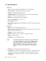
• Resolution/color depth:
Table 1.1:
Max. resolution
Color depth
LCD
800x600
16 bpp
CRT
800x600
16 bpp
LCD+CRT (dual
view)
640x480 (LCD) &
640x480 (CRT)
8 bpp (LCD) & 8 bpp
(CRT)
Environmental
• Operating temperature: 0~60 degree Celsius (32~140 degree Fahrenheit) fanless operation
• Storage temperature: -20~70 degree Celsius (4~158 degree Fahrenheit)
• Operating humidity: 0~90% relative humidity, non-condensing
5
Chapter 1
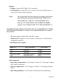
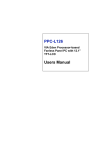
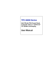
1.4 Dimensions and Board Layout
• Dimensions (L x W): 145 mm x 102 mm (5.9" x 4.2")
• Weight: 0.2 kg
Figure 1.1: Component Side
PCM-7130 User’s Manual
6
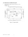
Figure 1.2: Component side
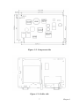
Figure 1.3: Solder side
7
Chapter 1
PCM-7130 User’s Manual
8
CHAPTER
2
Installation
This chapter tells how to set up the
PCM-7130 hardware. It includes all
connector locations and respective pin
assignments. Be sure to read all the
safety precautions before you begin the
installation procedure.
Chapter 2 Installation
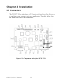
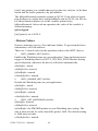
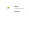
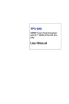
2.1 Connectors
The PCM-7130 has abundance of I/O ports and interfaces that allow you
to configure your system to suit your application. The table below lists
the function of each of the connectors:
CN3
CN8
Figure 2.1: Component side of the PCM-7130
PCM-7130 User’s Manual
10
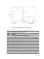
Figure 2.2: Solder side of the PCM-7130
Table 2.1 shows the list of all connector/ports on the PCM-7130.
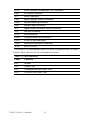
Table 2.1: Connectors on the PCM-7130
Label
Function
CN1
COM1 (full function RS-232) serial port
JP2
COM2 (full function RS-232) and COM3 RS-485 serial ports
CN2
10Base-T Ethernet port
CN13
PS/2 keyboard and mouse connector
J2
USB client (type B) connector
CN14
USB host (type A) connector
CN9
CRT display connector
CN8
TV-out connector
CN3
40-pin LCD display connector
J1
20-pin LVDS display connector
CN4
LCD inverter connector
JP13
4-wire resistive touchscreen connector
11
Chapter 2
JP14
4-wire resistive touchscreen FPC connector
CN6
DC power connector
JP1
Audio connector
CN5
Battery signals control connector
CN10
System wake-up connector
CN7
System reset connector
JP6
Digital inputs and digital output connector
JP9
Hot-key connector
JP15
IrDA connector
CN12
CompactFlash card connector
CN11
PCMCIA card connector
CN15
Expansion connector (reserved)
JP12
SA-110 JTAG*
*For moreJTAG information, please visit the Advantech RISC Alliance
Partner Zone web site at www.advantech.com/risc
Table 2.2: Miscellaneous
Label
Function
HP1
Buzzer
D11
Power LED
D12
CompactFlash RDY/nINT LED
D13
PCMCIA RDY/nINT LED
PCM-7130 User’s Manual
12
2.2 Pin Assignments
This section lists all the pin assignments of the connectors shown in the
Table 2.1.
CN1 is the COM1 full function RS-232 serial port connector
PAD
5
4
3
2
1
5
9
4
8
3
7
2
6
1
9
8
7
6
PAD
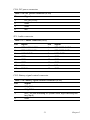
Table 2.3: COM1 RS-232 serial port (CN1)
Pin
Function
1
DCD
2
RXD
3
TXD
4
DTR
5
GND
6
DSR
7
RTS
8
CTS
9
RI
13
Chapter 2
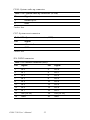
JP2 is COM2, the full function RS-232 and COM3 RS-485 serial ports
Table 2.4: COM2 RS-232 & COM3 RS-485 (JP2)
Pin
Function
1
DCD
2
DSR
3
RXD
4
RTS
5
TXD
6
CTS
7
DTR
8
RI
9
GND
10
N/C
11
DATA+ (RS-485)
12
DATA- (RS-485)
13
N/C
14
N/C
PCM-7130 User’s Manual
14
CN2: 10Base-T Ethernet port
Table 2.5: 10Base-T Ethernet port (CN2)
Pin
Function
1
XMT+
2
XMT-
3
RCV+
4
N/C
5
N/C
6
RCV-
7
N/C
8
N/C
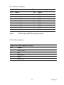
CN13: PS/2 keyboard/mouse connector
Table 2.6: PS/2 keyboard/mouse connector (CN13)
Pin
Function
1
KB DATA
2
MS DATA
3
GND
4
Vcc
5
KB CLK
6
MS CLK
15
Chapter 2
J2: USB client port
Table 2.7: USB client port (J2)
Pin
Function
1
N/C
2
USB_DATA-
3
USB_DATA+
4
GND
CN14: USB host port
Table 2.8: USB host port (CN14)
Pin
Function
1
USBVcc (5V)
2
USB_DATA-
3
USB_DATA+
4
GND
PCM-7130 User’s Manual
16
CN9: CRT display port (VGA-out)
Table 2.9: CRT display port VGA-out (CN9)
Pin
Function
1
RED
2
GREEN
3
BLUE
4
N/C
5
GND
6
GND
7
GND
8
GND
9
N/C
10
GND
11
N/C
12
N/C
13
H-SYNC
14
V-SYNC
15
N/C
CN8: TV-out connector
Table 2.10: TV-out (CN8)
1
Composite video out
2
GND
17
Chapter 2
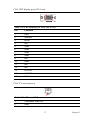
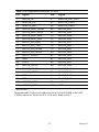
CN3: 40-pin LCD connector
Table 2.11: 40-pin LCD connector (CN3)
Pin
Signal
Pin
Signal
1
VDDSAFE5
2
VDDSAFE5
3
GND
4
GND
5
VDDSAFE3
6
VDDSAFE3
7
Reserved (for Vcon)*
8
GND
9
LCD_D0
10
LCD_D1
11
LCD_D2
12
LCD_D3
13
LCD_D4
14
LCD_D5
15
LCD_D6
16
LCD_D7
17
LCD_D8
18
LCD_D9
19
LCD_D10
20
LCD_D11
21
LCD_D12
22
LCD_D13
23
LCD_D14
24
LCD_D15
25
LCD_D16
26
LCD_D17
27
LCD_D18
28
LCD_D19
29
LCD_D20
30
LCD_D21
31
LCD_D22
32
LCD_D23
33
GND
34
GND
35
SHCLK
36
FLM
37
M/DE
38
LP
39
N/C
40
ENAVEE
*Vcon default voltage=24.4 V.Vcon can be adjusted by using System
Configurator.Vcon max=26.8 V, Vcon min=22.3 V. Vcon is only for
STN/DSTN LCD panel
PCM-7130 User’s Manual
18
LCD singal mapping
Table 2.12: LCD signal mapping
18-bit TFT Panel
16-bit DSTN Panel
LCD_D0
GND
GND
LCD_D1
GND
GND
LCD_D2
B0
GND
LCD_D3
B1
UD7
LCD_D4
B2
UD6
LCD_D5
B3
LD4
LCD_D6
B4
UD3
LCD_D7
B5
UD2
LCD_D8
GND
GND
LCD_D9
GND
GND
LCD_D10
G0
UD5
LCD_D11
G1
UD4
LCD_D12
G2
LD7
LCD_D13
G3
UD1
LCD_D14
G4
UD0
LCD_D15
G5
LD3
LCD_D16
GND
GND
LCD_D17
GND
GND
LCD_D18
R0
GND
LCD_D19
R1
LD6
LCD_D20
R2
LD5
LCD_D21
R3
LD2
LCD_D22
R4
LD1
LCD_D23
R5
LD0
19
Chapter 2
J1: 20-pin LVDS display connector
Table 2.13: 20-pin LVDS connector (J1)
Pin
Signal
Pin
Signal
1
VDD (+3V)
2
VDD (+3V)
3
GND
4
GND
5
TX0-
6
TX0+
7
GND
8
TX1-
9
TX1+
10
GND
11
TX2-
12
TX2+
13
GND
14
TX3-
15
TX3+
16
GND
17
TXCK-
18
TXCK+
19
GND
20
GND
CN4: LCD inverter connector
Table 2.14: LCD inverter connector (CN4)
Pin
Signal
1
DC_IN (+12V)
2
GND
3
ENABKL
4
VBR
5
N/C
JP13, JP14: 4-wire touchscreen connector
Table 2.15: 4-wire touchscreen connector
Pin
Signal
1
X-
2
X+
3
Y-
4
Y+
PCM-7130 User’s Manual
20
CN6: DC power connector
Table 2.16: DC power connector (CN6)
Pin
Signal
1
DC_IN (+12V)
2
GND
3
GND
4
N/C
JP1: Audio connector
Table 2.17: Audio connector (JP1)
Pin
Signal
Pin
Signal
1
SPEAKER OUT R+
2
SPEAKER OUT R-
3
SPEAKER OUT L+
4
SPEAKER OUT L-
5
LINE OUT R
6
LINE OUT L
7
GND
8
GND
9
GND
10
GND
11
GND
12
GND
13
N/C
14
N/C
15
MIC IN
16
GND
CN5: Battery signal control connector
Table 2.18: Battery signal control connector (CN5)
Pin
Signal
1
SM_CLK
2
SM_DATA
3
nDC_IN (low indicating DC power used; high indicating battery input)
4
GND
21
Chapter 2
CN10: System wake-up connector
Table 2.19: System wake-up connector (CN10)
Pin
Signal
1
nWake-up in*
2
GND
*active low
CN7: System reset connector
Table 2.20: System reset connector (CN7)
Pin
Signal
1
nReset in*
2
GND
*active low
JP6: DI/DO connector
Table 2.21: DI/DO connector (JP6)
Pin
Signal
Pin
Signal
1
DI 0
2
DO 0
3
DI 1
4
DO 1
5
DI 2
6
DO 2
7
DI 3
8
DO 3
9
DI 4
10
DO 4
11
DI 5
12
DO 5
13
DI 6
14
DO 6
15
DI 7
16
DO 7
17
Vcc (+3.3V)
18
Vcc (+3.3V)
19
GND
20
GND
PCM-7130 User’s Manual
22
JP9: Hot-key connector
Table 2.22: Hot-key connector (JP9)
Pin
Signal
Pin
Signal
1
Hot key 1*
2
GND
3
Hot key 2*
4
GND
5
Hot key 3*
6
GND
7
Hot key 4*
8
GND
9
Hot key 5*
10
GND
11
Hot key 6*
12
GND
13
Hot key 7*
14
GND
15
Hot key 8*
16
GND
Note:
All hot keys (GPIOs) are low active
JP15: IrDA connecor
Table 2.23: IrDA connector (JP15)
Pin
Signal
1
Vcc (+3.3V)
2
N/C
3
IrDA RXD
4
GND
5
IrDA TXD
23
Chapter 2
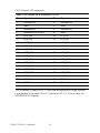
CN 15: Expansion connector
Table 2.24: Expansion connector (CN15)
Pin
Signal
Pin
Signal
1
SA1110_A0
2
nSA1110_RST_OUT*
3
SA1110_A1
4
SA1110_RD_nWR
5
SA1110_A2
6
SA1110_RDY
7
SA1110_A3
8
nSA1110_CS3*
9
SA1110_A4
10
SA1110_PWR_EN
11
SA1110_A5
12
nSA1110_IOIS16*
13
SA1110_A6
14
Reserved
15
SA1110_A7
16
Reserved
17
SA1110_A8
18
GND
19
SA1110_A9
20
+3.3V
21
SA1110_A10
22
SA1110_D15
23
SA1110_A11
24
SA1110_D14
25
SA1110_A12
26
SA1110_D13
27
SA1110_A13
28
SA1110_D12
29
SA1110_A14
30
SA1110_D11
31
SA1110_A15
32
SA1110_D10
33
GND
34
SA1110_D9
35
+3.3V
36
SA1110_D8
37
SA1110_A16
38
SA1110_D7
39
SA1110_A17
40
SA1110_D6
41
SA1110_A18
42
SA1110_D5
43
SA1110_A19
44
SA1110_D4
45
SA1110_A20
46
SA1110_D3
47
SA1110_A21
48
SA1110_D2
49
SA1110_A22
50
SA1110_D1
51
SA1110_A23
52
SA1110_D0
53
SA1110_A24
54
GND
55
SA1110_A25
56
+5V
57
GND
58
nSA1110_CAS0*
59
+5V
60
nSA1110_CAS1*
PCM-7130 User’s Manual
24
Table 2.24: Expansion connector (CN15)
Pin
Signal
Pin
Signal
1
SA1110_A0
2
nSA1110_RST_OUT*
61
nSA1110_OE*
62
nSA1110_CAS2*
63
nSA1110_WE*
64
nSA1110_CAS3*
65
SA1110_MCP_SFRM
66
SA1110_D31
67
SA1110_MCP_SCLK
68
SA1110_D30
69
SA1110_MCP_RXD
70
SA1110_D29
71
SA1110_MCP_TXD
72
SA1110_D28
73
SA1111_SPI_RXD
74
SA1110_D27
75
SA1111_SPI_TXD
76
SA1110_D26
77
SA1111_SPI_SFRM
78
SA1110_D25
79
SA1111_SPI_SCLK
80
SA1110_D24
81
SA1111_GPIO0
82
SA1110_D23
83
GND
84
SA1110_D22
85
+3.3V
86
SA1110_D21
87
SA1110_GPIO2
88
SA1110_D20
89
SA1110_GPIO3
90
SA1110_D19
91
SA1111_GPIO14
92
SA1110_D18
93
GND
94
SA1110_D17
95
GND
96
SA1110_D16
97
nSA1110_CS1*
98
+3.3V
99
nSA1110_CS2*
100
GND
*Active low
Recommend I/O physical addresses from 0x1A80 0000h to 0x1AFF
FFFFh which are located at SA-1110 static bank select 3.
25
Chapter 2
2.3 Peripherals Connection
The RISC/Windows CE combination is good for purposed applications.
However, it means at the same time that this kind of platform could not be
the same as ordinary personal computers. This section provides a reference for connecting peripherals.
2.3.1 LCD Display
PCM-7130 supports both active and passive LCD displays. Nevertheless,
the specifications of various LCD diverse substantially. Hereby a list is
given to show those LCD supported by PCM-7130. The newest supporting list will be included in a progressive technical reference by Advantech. Please contact with local Advantech representatives or surf the
website of Advantech: http://support.advantech.com
The PCM-7130 supports
-PrimeView 6.4” VGA TFT LCD
PD064VT2T1
-Nan-ya 7.4” VGA DSTN LCD
LCBLDT163M9T
-Unipac 10.4" SVGA LVDS TFT LCD(UB104S01-1)
2.3.2 CRT Display
The PCM-7130 supports display on CRT monitors. In addition, it can also
give dual view on CRT and LCD display. Refer to the section 1.3 for the
related information.
2.3.3 Touchscreen
The default touchscreen control and connector are for 4-wire resistive
touchscreen.
2.3.4 USB Host
The USB host port on the PCM-7130 is USB 1.1 compatible. The default
Windows CE.NET and Linux on board support USB keyobards and mice.
To connect other devices it may take customization on the Windows CE.
2.3.5 USB Client
The USB client port is used for data synchronization between PCM-7130
and master devices (or server devices). The USB client cable enclosed in
the package is used for this purpose.
PCM-7130 User’s Manual
26
2.3.6 RS-232/RS-485 COM Port
There are 3 serial ports on the PCM-7130. The COM1 has a DB-9 connector. On the other hand, the COM2 and COM3 (RS-232 and RS-485)
share the same 14-pin header.
2.3.7 DI/DO
There are 8-channel digital input and 8-channel digital output on the
PCM-7130. They can be used for simple on/off control.The high level
voltage is 3.3V.
Warning!
Be careful when these DI/DO are used. Surge or
over voltage may damage the circuits.
27
Chapter 2
PCM-7130 User’s Manual
28
CHAPTER
3
Windows CE.NET on
the PCM-7130
This chapter details the Windows
CE.NET operating system on the PCM7130.
Sections include:
• Starting PCM-7130
• Windows CE.NET utility on the
PCM-7130
• PCM-7130 Networking
• Intel Persistent Storage Manager(IPSM)
• Application Program Development
• Advantech Windows CE.NET standard pack
Chapter 3 Windows CE on the PCM-7130
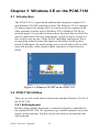
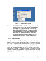
3.1 Introduction
The PCM-7130 is a single board platform that integrates complete I/O
and Windows CE.NET operating system. The Windows CE is a compact
OS that occupies less storage space or system resources compared with
other operating systems such as Windows NT or Windows XP. By its
modular nature, it is possible to choose those functions that are useful for
specific application. Not only reducing the system resources required, it
also reduces start-up time. In the field of embedded applications, this is
an appealing feature because the impact of downtime would be minimized. Furthermore, the small storage space it needs makes OS on solidstate disk possible, which implies higher robustness to harsh environments.
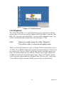
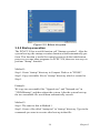
Figure 3.1: Windows CE.NET on the PCM-7130
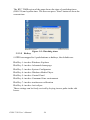
3.2 PCM-7130 Utilities
There are several useful utilities built in the standard Windows CE OS of
the PCM-7130:
3.2.1 Soft-keyboard
Besides using ordinary keyboards, a software keyboard is embedded in
the standard PCM-7130 OS. Upon boot-up, a small keyboard icon would
appear on the status bar. Tap this icon by the stylus to activate/hide this
soft-keyboard.
PCM-7130 User’s Manual
30
Figure 3.2: Soft-keyboard
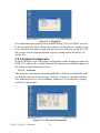
3.2.2 Regflash
The utility "Regflash" is a convenient tool to save, overwrite or delete
registry data, as well as erase the content of IPSM folder. From the Windows CE status bar, tap "Start/Run". Use the soft-keyboard to type "regflash" command in the command text box and press "OK".
Note:
Please be careful using this utility "Regflash".
This utility is able to overwrite all registry data.
There are four selections here: Save to Flash, Delete from Flash, Save to
CF Disk, Erase IPSM. Choose the options you want and press "Save" button to proceed. "Save to Flash" option was used to save the registry setting to on board flash rom. In contrast, "Delete from Flash" option was
intended to erase the on board registry data. "Save to CF Disk" option
would save the registry data to Compact Flash Card as a file "wince.reg".
"Erase IPSM" option erase the IPSM region of the on board flash.
31
Chapter 3
Figure 3.3: Regflash
It is important to keep the power normal during "Save to Flash" process.
If the power break down during the registry saving process, then the registry would be lost and corrupt. On the next time you turn on PCM-7130,
the system would load the default registry setting in the Windows CE
image file
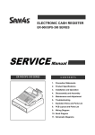
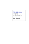
3.2.3 System Configurator
Double click the icon of System Configurator on the desktop to open the
PCM-7130 utility. We would illustrate the functions in different pages of
the utility in the following sections.
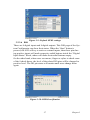
3.2.3.1 General
The memory information including DRAM, CF Disk and IPSM FLASH
are displayed in the General page. And the version of installed software
was indicated here as well, including windows CE, bootloader, registry
and this Configurator.
Figure 3.4: General information
PCM-7130 User’s Manual
32
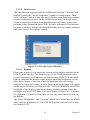
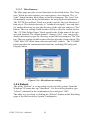
3.2.3.2 Touchscreen
The Touchscreen page provides the calibration function. Click the "calibration" button, the "Stylus Properties" windows would appear. Then
click "calibrate" button in the Advantech Touchscreen Properties window
to enter calibration process. In the calibration process, user taps on the
center of the target on the screen then the target will move to the next
position. After calibration, press "OK" to leave Advantech Touchscreen
Properties window, and then the Regflash utility process would automatically start to save the registry setting.
Figure 3.5: Touchscreen calibration
3.2.3.3 Display
From time to time it is unnecessary to turn on the display attached to the
PCM-7130 all the day. The Display page of the Configurator provides
several frequently used functions such as turning off the LCD and backlight to elongates the display repair period, adjusting brightness or contrast. For example, if the user wants the backlight turn-off setting
function,he can press"setting" button.Then the backlight page will appear
on the screen. Besides, user can click the "Off Now" button to turn off the
backlight of the display panel immediately without waiting. Once the
backlight was turned off, there were three inputs to turn it on: (1) mouse;
(2) keyboard; (3) touch screen; user can use any one of them to turn on
the display.
The lower “Brightness” and “Contrast” blocks have scroll bars by which
users can tune brightness level of TFT LCD or the contrast level of passive matrix LCD.
33
Chapter 3
Figure 3.6: Display controls
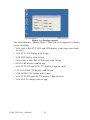
The lowest block is “Display Mode”. The PCM-7130 supports 10 display
modes including:
• VGA (640 x 480) TFT LCD and CRT display, with 8 bpp color depth
for each
• VGA TFT LCD display with 16 bpp
• VGA CRT display with 16 bpp
• SVGA (800 x 600) TFT LCD display with 16 bpp
• SVGA CRT display with 16 bpp
• VGA TFT LCD and NTSC TV display, 8 bpp for each
• 672 x 436 NTSC TV display with 16 bpp
• VGA DSTN LCD display with 16 bpp
• VGA TFT LCD and PAL TV display, 8 bpp for each
• VGA PAL TV display with 16 bpp
PCM-7130 User’s Manual
34
Figure 3.7: Display mode setting
Note:
1. VGA TFT LCD and CRT display is the default
setting of the PCM-7130. This will facilitate users
to develop AP or products if the LCD has not
been determined. However, it is recommend to
change the display mode because 8 bpp color
depth may not be appreciated for most users.
2. As new display mode is set, the PCM-7130
takes reset or reboot to activate new setting.
3.2.3.4 WatchDog timer
It is important in industrial applications that the control systems are rarely
crashed, or are capable of self-reset if they are halted somehow. The
watchdog timer is therefore used in the PCM-7130 to provide automatic
reset. There is a timer inside the watchdog timer. The PCM-7130 should
clear the timer within a pre-set time interval periodically. If the timer was
not cleared, the timer would assume the system to be halted and generate
a reset. The watchdog timer in the PCM-7130 provides eight different
time intervals: 2 seconds, 5 seconds, 10 seconds, 30 seconds, 60 seconds,
2 minutes, 5 minutes and 10 minutes. Choose the appropriate time interval, and then press "Enable" button to enable the watchdog function. The
"REBOOT" button provide the warm boot function to reboot the device.
35
Chapter 3
The RTC TIME region of the page shows the time of watchdog timer
(DS1670) and system time. The user can press "Start" button to show the
current time.
Figure 3.8: Watchdog timer
3.2.3.5 Hotkey
8 GPIO are mapped to 8 push-buttons as hotkeys, the defaults are:
Hot Key 1: invokes Windows Explorer
Hot Key 2: invokes Advantech homepage
Hot Key 3: invokes System Configurator
Hot Key 4: invokes Windows Media Player
Hot Key 5: invokes Control Panel
Hot Key 6: invokes Command Line environment
Hot Key 7: invokes touchscreen calibration
Hot Key 8: invokes ActiveSync
These settings can be freely revised by keying in new paths in the edit
boxes.
PCM-7130 User’s Manual
36
Figure 3.9: Default GPIO settings
3.2.3.6 DIO
There are 8 digital inputs and 8 digital outputs. This DIO page of the System Configurator can show their status. When the “Start” button is
pressed, the 8 DI will try to retrieve external inputs, then those pins having positive inputs will mark respective radial buttons inside the “Digital
Input Status” block, others will make their radial buttons empty.
On the other hand, when users use mouse, finger or stylus to check some
of the 8 check boxes, the level of the related DO pins will be changed to
positive level. The DO pin status will sustain until users change them
again.
Figure 3.10: DI/DO verification
37
Chapter 3
3.2.3.7 Miscellaneous
The Misc page provides several functions as described below. The "Registry" block provides registry save and registry view function. The “A.
Sync” button invokes ActiveSync to the host computer. The "reset" button manually resets the keyboard/mouse for hot-plug keyboard/mouse.
The "HTTP Server Root" block was used to specify the root directory of
http server. The default directory is "\windows\wwwpub", user can specify another directory by type the directory in the edit box and press "Set"
button. The new setting would become effective after the system reboot.
The “CF Disk Folder Name” block specifies the folder name of the storage card inserted. The default name is “Storage Card”. user can specify
another directory by type the directory in the edit box and press "Set" button. The new setting would become effective after the system reboot. The
"SMC MAC ID" block shows the network MAC address. The "COMM"
block provides the communication functions, including IPConfig and
Pinging Yahoo.
Figure 3.11: Miscellaneous settings
3.2.4 Reboot
The utility "Reboot" is a convenient tool to reset the system. From the
Windows CE status bar, tap "Start/Run". Use the soft-keyboard to type
"reboot" command in the command text box and press "OK".
The other way to reboot is clicking the “Reboot” button on the Watchdog
page of the built-in utility System Configurator.
PCM-7130 User’s Manual
38
Figure 3.12: Reboot the system
3.2.5 Startup execution
The PCM-7130 has a useful function call "Startup execution". After the
system boot up, the startup execution function would automatically perform. This function is useful for control system to do the initialization
processes or some other programs. In PCM-7130, there are two ways to
perform "Starup" function.
Method 1:
Step1: Create "startup" directory in Compact Flash or in "\IPSM\".
Step2: Copy executable files to "startup" directory which is created in
Step 1.
Example:
We copy two executable files "Upgrade.exe" and "Notepad.exe" in
"\IPSM\Startup", and then reboot the system. After the system boot up,
the two executable file would been automatically execute.
Method 2:
Step1: The same as that in Method 1.
Step2: Create a file called "startup.ini" in "startup" directory. Type in the
commands you want to execute after boot up in that file.
39
Chapter 3
Example:
Create "Startup.ini" in "\IPSM\Startup" directory and reboot the system.
The content of startup.ini was listed below:
\windows\tty.exe
\windows\registry.exe
After the system reboot, "\windows\ tty.exe" and "\windows\ registry.exe"
would be executed automatically.
Be sure that the two methods are independent, it means they can be used
simultaneously.
3.2.6 Safemode
PCM-7130 utilities allow user to alter registry setting, and save it by
either "regflash.exe" or the registry frame of the “Misc” page of the Configurator. But sometimes user may make some non-appropriate registry
setting, and cause PCM-7130 fail to boot. In the circumstance, the easiest
way to boot up PCM-7130 is to use the default registry setting from the
WinCE image. When the PCM-7130 is booted up with the default registry setting, we say that it is working in "safemode". To enter "safemode",
user must perform several steps as described below:
Step 1: Create a file whose filename is "safemode" or a directory whose
name is "safemode" in the Compact Flash Card.
Step 2: Insert the Compact Flash Card into the PCM-7130.
Step 3: Turn on the power of PCM-7130.
The registry searching sequence of the PCM-7130 was described in
Appendix.
PCM-7130 User’s Manual
40
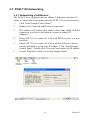
3.3 PCM-7130 Networking
3.3.1 Networking via Ethernet
The PCM-7130 is equipped with one 10Base-T Ethernet controller. To
utilize it, change the device name when the PCM-7130 is first turned on.
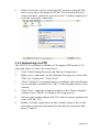
1.
Click "Start/Settings/Control Panel"
2.
Double click "Network and Dial-up Connections"
3.
This window will display all available connections. Right-click the
connection icon users could disable, rename or modify IP
addresses.
4.
If the PCM-7130 is a node of a LAN with DHCP servers, it is now
available.
5.
If the PCM-7130 is a node of a LAN with fixed IP server, please
consult with MIS to get specific IP address. Click "Start/Settings/
Control Panel". Double click "Network" and update the IP address.
6.
Use the "Regflash" utility to save this changed name.
41
Chapter 3
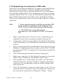
3.3.2 Networking via serial port or USB cable
The PCM-7130 with built-in Windows CE supports serial and USB port
connection to host computers. The host computer must install the
Microsoft ActiveSync service offered by Microsoft. Use a null modem
cable bundled with the PCM-7130 to connect the serial ports of the host
computer and the PCM-7130. Or use the USB cable to connect the USB
ports of them. Then activate ActiveSync service on the host computer.
The host will automatically scan its serial ports and USB ports to make a
connection.
Note:
1. Users should properly install the associated USB
driver on the host computer while plugging in the
PCM-7130 as a USB client device at the first time.
2. The USB driver--wceusbsh.inf and
wceusbsh.sys--are included in PCM-7130 support
CD.
1.
Make sure the Microsoft ActiveSync service and the Microsoft
embedded Visual Tools are properly installed in the host PC.
2.
Connect the two RS-232 ports of the host PC and the PCM-7130 by
a null modem cable or use USB cable to connect the two USB ports
of them.
3.
If users are using the Microsoft eMbedded Visual Tools to develop
Windows CE application runtimes, make sure the PCM-7130 SDK
provided in the PCM-7130 support CD is also properly installed in
the host PC.
4.
Click "Start/Settings/Network and Dial-up Connections"
5.
Make a new connection. As the dialogue box pops out, choose the
default "Direct Connection" radial button. Click "Next".
6.
Select whether to use "Serial Cable on COM1:" or "USB Cable"
from the combo box, and click "Finish" to complete making new
connection. It is recommended to keep the default settings of the
ports connection.
7.
Click “PC Connection” icon in the Control Panel. As the “PC Connection Properties” dialogue box pops up, change the connection to
the newly made connection by clicking the “Change...” button.
PCM-7130 User’s Manual
42
8.
If the ActiveSync service on the host PC has been activated, the
above seven steps will make the PCM-7130 automatically try to
connect the host, ;otherwise you can invoke "\windows\reglog.exe"
to do the activesync connection.
3.3.3 Networking via PPP
The PCM-7130 with built-in Windows CE supports PPP protocol. To
setup and utilize it, follow the steps below:
1.
Click "Start/Settings/Network and Dial-up Connections”
2.
Make a new connection. As the dialogue box pops out, choose the
"Dial-Up Connection". Click "Next".
3.
Click "Configure" to setup the device according to the specification
of your modem, and then click "OK" on the top-right corner of the
window.
4.
Click "Next". Input the telephone number in the "Phone Number"
window. Press "Finish" to complete the setup process.
5.
Turn on your modem and use RS-232 cable to connect modem and
com1 of PCM-7130.
6.
Double click the connection you have made in Step 4. Key in the
user name, password and domain for the dial-up connection and
press "Connect".
43
Chapter 3
3.3.4 Web browser
The PCM-7130 built-in Windows CE OS includes IESample. It can be
used to browse web pages on World Wide Web via LAN or PPP.
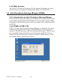
3.4 Intel Persistent Storage Manger (IPSM)
3.4.1 Introduction to Intel Persistent Storage Manger
Intel Persistent Storage Manager was designed and developed specifically
as an enhancement to Microsoft Windows CE operating systems. PSM
eliminates extra disk-like storage such as storage cards, redundant RAM
and ROM.
3.4.2 IPSM in PCM-7130
PCM-7130 uses Intel Persistent Storage Manger to utilize the free space
of flash rom for persistent storage. The IPSM region in the system is
locate in "\IPSM" directory. Any file or directory stored in "\IPSM" directory would be keep persistently, even if the power of PCM-7130 was
turned off. The user can store software or data in \IPSM rather in Compact Flash Card to avoid inconvenience.
PCM-7130 User’s Manual
44
3.5 Application Program Development
The PCM-7130 is bundled with built-in Windows CE operating system.
In real applications users need to execute various application programs on
it. However, unlike its other family the Windows CE is a hardwaredependent operating system. That is to say, Windows CE application programs are only portable in the source code level. Users must rebuild the
runtime file for a different Windows CE platform even though the source
code may not be changed at all.
3.5.1 System requirements
• Intel Pentium-90 CPU or more advanced
• Microsoft Windows 2000 Professional or Windows NT Workstation 4.0
• Microsoft eMbedded Visual Tools 3.0
• Platform SDK for PCM-7130 (bundled in the standard PCM-7130)
• 64MB DRAM
• CD-ROM drive
• Monitor with VGA resolution at least
• Mouse
• 200MB free hard disk space at least
• Connection to the same LAN as the PCM-7130 if LAN is used for
development PCM-7130
• PCM-7130
• Connection to the same LAN as the host PC if LAN is used for development
• Null modem cable (bundled in the standard PCM-7130)
• USB cable (bundled in the standard PCM-7130)
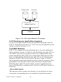
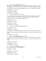
3.5.2 Building Windows CE runtime
By the platform SDK bundled with the standard PCM-7130, users can
build the Windows CE runtime by the eMbedded Visual Tools.
45
Chapter 3
AP Source Code
ADV_ARM
Socer-320
SDK
eMbedded Visual Tools
AP Runtime
Figure 3.13: Flow-chart Windows CE runtime
3.5.3 Running your application programs
Use the Activesync function to put your application programs onto the
PCM-7130 platform (reference 3.3). Users can run your application with
startup execution (reference 3.2.5).
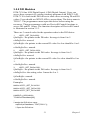
3.5.4 WDT Modules
PCM-7130 is targeted to be the embedded device for web-enabled and
data-acquisition systems. It is built-in with Watchdog timer and LCD onoff control. Users can access these resources by writing windows programs with WIN32 API. PCM-7130 is built-in the WDT driver to allow
users to enable/disable Watchdog timer and LCD on-off control. Users
should use WIN32 APIs to access them. The driver name is "WDT1:".
The programmers must open this driver before using the resources. Then
programmers could use DeviceIOControl functions to enable/disable
Watchdog timer and LCD on-off control. At most 5 applications can
access watchdog timer simultaneously. The DeviceIOControl function is
following:
- DeviceIoControl
This function sends a control code directly to a specified device driver,
causing the corresponding device to perform the specified operation.
PCM-7130 User’s Manual
46
BOOL DeviceIoControl(
HANDLE hDevice,
DWORD dwIoControlCode,
LPVOID lpInBuffer,
DWORD nInBufferSize,
LPVOID lpOutBuffer,
DWORD nOutBufferSize,
LPDWORD lpBytesReturned,
LPOVERLAPPED lpOverlapped );
- Parameters
hDevice
[in] Handle to the device that is to perform the operation. Call the CreateFile function to obtain a device handle.
dwIoControlCode
[in] Specifies the control code for the operation. This value identifies the
specific operation to be performed and the type of device on which the
operation is to be performed. No specific values are defined for the dwIoControlCode parameter. However, the writer of a custom device driver
can define IOCTL_XXXX control codes, per the CTL_CODE macro.
These control codes can then be advertised, and an application can use
these control codes with DeviceIoControl to perform the driver-specific
functions.
lpInBuffer
[in] Long pointer to a buffer that contains the data required to perform the
operation.
This parameter can be NULL if the dwIoControlCode parameter specifies
an operation that does not require input data.
nInBufferSize
[in] Size, in bytes, of the buffer pointed to by lpInBuffer.
lpOutBuffer
[out] Long pointer to a buffer that receives the operation's output data.
This parameter can be NULL if the dwIoControlCode parameter specifies
an operation that does not produce output data.
nOutBufferSize
[in] Size, in bytes, of the buffer pointed to by lpOutBuffer.
lpBytesReturned
47
Chapter 3
[out] Long pointer to a variable that receives the size, in bytes, of the data
stored into the buffer pointed to by lpOutBuffer.
The lpBytesReturned parameter cannot be NULL. Even when an operation produces no output data, and lpOutBuffer can be NULL, the DeviceIoControl function makes use of the variable pointed to by
lpBytesReturned. After such an operation, the value of the variable is
without meaning.
lpOverlapped
[in] Ignored; set to NULL.
- Return Values
Nonzero indicates success. Zero indicates failure. To get extended error
information, call GetLastError.
There are 7 control codes for the operation codes in the WDT1 driver:
1.
IOCTL_ENABLE_WDT (0x1001):
Enables the Watchdog timer on your application. Your application must
trigger to Watchdog timer by IOCTL_ACCESS_WDT interface during
specified period, otherwise the device will reboot automatically
lpInBuffer : unsed.
nInBufferSize: unused.
lpOutBuffer: unused.
nOutBufferSize: unused.
2.
IOCTL_DISABLE_WDT (0x1002):
Disable the Watchdog time on your application.
lpInBuffer : unsed.
nInBufferSize: unused.
lpOutBuffer: unused.
nOutBufferSize: unused.
3.
IOCTL_GET_WDTPERIOD (0x1003):
lpInBuffer :unused.
nInBufferSize: unused.
lpOutBuffer: the DWORD pointer to your Watchdog time setting. The
unit is mini-second. Its value should be greater 1000. The default setting
is 5000 mini-seconds.
nOutBufferSize: unused.
PCM-7130 User’s Manual
48
4.
IOCTL_SET_WDTPERIOD (0x1004):
lpInBuffer : the DWORD pointer to your Watchdog time setting. Its vlaue
should be greater 1000. The unit is mini-second. If your application open
the WDT driver, the default Watchdog Time is set to 5000 mini-seconds.
nInBufferSize:.unused.
lpOutBuffer: unused.
nOutBufferSize: unused.
5.
IOCTL_ACCESS_WDT (0x1005):
Your application must trigger the Watchdog once during the your Watchdog timer period. If your application has not trigger at the specified
period, the device will reboot automatically.
lpInBuffer :unused.
nInBufferSize:.unused.
lpOutBuffer: unused.
nOutBufferSize: unused.
6.
IOCTL_GET_SCREENOFFTIME (0x1006):
lpInBuffer :unused.
nInBufferSize: unused.
lpOutBuffer: the DWORD pointer to your screen off time if user-interface
idled. The unit is mini-second. If the value is 0, screen-off function is disabled.
nOutBufferSize: unused.
7.
IOCTL_SET_SCREENOFFTIME (0x1007):
lpInBuffer : the DWORD pointer to your screen off time if user-interface
idled. The unit is mini-second. If the value is 0, screen-off function is disabled.
nInBufferSize:unused.
lpOutBuffer: unused.
nOutBufferSize: unused.
8.
IOCTL_SET_SCREENOFF (0x1010):
Set the LCD power off immediately.
lpInBuffer : unused.
nInBufferSize:.unused.
lpOutBuffer: unused.
nOutBufferSize: unused.
49
Chapter 3
Examples:
#define IOCTL_ENABLE_WDT 0x1001
#define IOCTL_DISABLE_WDT 0x1002
#define IOCTL_GET_WDTPERIOD 0x1003
#define IOCTL_SET_WDTPERIOD 0x1004
#define IOCTL_ACCESS_WDT 0x1005
#define IOCTL_GET_SCREENOFFTIME 0x1006
#define IOCTL_SET_SCREENOFFTIME 0x1007
HANDLE m_hWDT=NULL;
TCHAR szClassName[60];
...
// assign the WDT driver name
wsprintf(szClassName, TEXT("WDT1:"));
// Open the DIO driver
m_hWDT = CreateFile(szClassName, GENERIC_READ | GENERIC_WRITE, 0,
NULL,
OPEN_EXISTING, FILE_ATTRIBUTE_NORMAL, NULL);
if ( m_hWDT == INVALID_HANDLE_VALUE ) {
DebugMsg(CString("WDT driver fail"));
return;
}
...
DWORD dwTemp;
DWORD nPeriod=10000;
// Set the Watchdog Timer as 10 seconds (10000 mini-seconds)
DeviceIoControl(m_hWDT, IOCTL_SET_WDTPERIOD, &nPeriod, 4, NULL, 0,
&dwTemp, NULL);
// Enable the Watchdog timer
DeviceIoControl(m_hWDT, IOCTL_ENABLE_WDT, NULL, NULL, NULL, 0,
&dwTemp, NULL);
While (1) {
// do your job here...
Sleep(8000);
DeviceIoControl(m_hWDT, IOCTL_ACCESS_WDT, NULL, NULL, NULL, 0,
&dwTemp, NULL);
}
DeviceIoControl(m_hWDT, IOCTL_DISABLE_WDT, NULL, NULL, NULL, 0,
NULL, NULL);
CloseHandle(m_hWDT);
PCM-7130 User’s Manual
50
3.5.5 DIO Modules
PCM-7130 has 8 DI(Digital Input), 8 DO(Digital Output). Users can
access these resources by writing windows programs with WIN32 API.
PCM-7130 is built-in the DIO driver to allow users accessing DI and DO
values. Users should use WIN32 APIs to access them. The driver name is
"DIO1:". The programmers must open this driver before using the
resources. Then programmers could use DeviceIOControl functions to
access DO and DI values. The function description of DeviceIOControl
is illustrated in section 3.5.3.
There are 3 control codes for the operation codes in the DIO driver:
1.
IOCTL_GET_DI(0x1002):
lpInBuffer : the pointer to the DI index. Its range is from 0 to 5.
nInBufferSize: unused.
lpOutBuffer: the pointer to the current DI value. Its vlue should be 0 or 1.
nOutBufferSize: unused.
2.
IOCTL_GET_DO(0x1003):
lpInBuffer : the pointer to the DO index. Its range is from 0 to 5.
nInBufferSize: unused.
lpOutBuffer: the pointer to the current DI value. Its value should be 0 or
1.
nOutBufferSize: unused.
3.
IOCTL_SET_DO(0x1005):
lpInBuffer : the pointer to the DO index. Its range is from 0 to 5.
nInBufferSize: the setting value. It must be 0 or 1.
lpOutBuffer: unused.
nOutBufferSize: unused.
Examples:
#define IOCTL_GET_DI 0x1002
#define IOCTL_GET_DO 0x1003
#define IOCTL_SET_DO 0x1005
HANDLE g_hDIO=NULL;
TCHAR szClassName[60];
...
// assign the DIO driver name
wsprintf(szClassName, TEXT("DIO1:"));
// Open the DIO driver
51
Chapter 3
g_hDIO = CreateFile(szClassName, GENERIC_READ | GENERIC_WRITE, 0,
NULL,
OPEN_EXISTING, FILE_ATTRIBUTE_NORMAL, NULL);
if ( g_hDIO == INVALID_HANDLE_VALUE ) {
DebugMsg(CString("DIO driver fail"));
return; }
...
// Get the DO 2 value into nV
DWORD dwTemp;
DWORD nDO = 2;
int nV;
DeviceIoControl(g_hDIO, IOCTL_GET_DO, (LPVOID)&nDO, 4, (LPVOID)&nV, 4,
&dwTemp, NULL);
CloseHandle(g_hDIO);
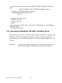
3.6 Advantech Windows CE.NET standard pack
This section will describe detailed requirements on hardware support and
Windows CE.NET component as below. Users can upgrade their OS
image using the "Advantech Upgrade" tool to develop or upgrade the OS
version.
Caution:
This action maybe damaged the system,if you really need
this function,please contact www.advantech.com/risc
PCM-7130 User’s Manual
52
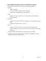
3.6.1 Detailed requirements on hardware support
• WDT: provides sample code for period setting on manual
• Battery:
-battery gauging
-25% low-battery warning event, adjustable
-battery/DC-in/charging icons on status bar
• SSD:
-higher priority to boot if the CF card contains bootable image
-Hot swappable
• PCMCIA:
-supports CF card with PCMCIA adapter as non-bootable storage
card
-
-supports Advantech WLAN cards
• PS/2:
-supports keyboard, mouse and touchscreen simultaneously
-keyboard/mouse will not interfere each other and the touchscreen
-hot plug
• Serial ports: RS-485 has hardware data flow control ability
• USB host: supports keyboards/mice. Standard compatible item list
should be the same as that of QE
53
Chapter 3
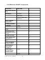
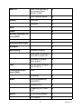
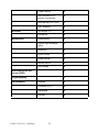
3.6.2 Windows CE.NET Components
Component
Sub-comp.
Basic kernel, drivers
& UI
ActiveSync
V
File Sync
V
Inbox Sync
X
Pocket Outlook Database Sync
X
Active Template
Library (ATL)
V
C library & runtime
V
COM/DOM
COM
V
DCOM
X
SNMP
V
Lightweight Directory Access Protocol
(LDAP)
V
Message queuing
V
SOAP reliable message protocol
V
MFC
V
OBject EXchange
protocol (OBEX)
V
Pocket Outlook
Object Model
(POOM) API
X
Simple Object
Access Protocol
(SOAP) toolkits
PCM-7130 User’s Manual
Client
V
Server
V
54
XML 3.0
Games
XML core services &
Document Object
Model (DOM)
V
XML minimal parser
X
Free cell
X
Solitaire
X
Help
V
Inbox
X
Remote Desktop Protocol (RDP)
V
Terminal emulator
V
Windows messenger
V
Wordpad
V
Networking
Network bridging
V
Real-time Communication (RTC) client API
V
Universal Plug and
Play (UpnP)
V
LAN
WLAN zero configuration & 802.1x
V
Personal Area Network (PAN)
IrDA
V
Bluetooth
X
Dial-up Networking
(RAS/PPP)
V
VPN (PPTP)
V
Telephony API (TAPI
2.0)
V
Core server support
V
FTP server
V
WAN
Server
55
Chapter 3
Browser
Multimedia
Telnet server
V
RAS server/PPTP
server (incoming)
V
Web server (HTTPD)
V
ASP support
V
IESample 5.5
V
Pocket IE
X
DirectMusic
V
Digital right management
V
Direct3D
V
Direct Draw
V
Direct Show
V
Media player
V
DVD-video
V
Authentication services (SSPI)
V
Cryptography
V
Localization
PCM-7130 User’s Manual
English
V
Chinese (S)(T)
X
Japanese
X
Korean
X
56
Appendix
Registry Searching
Sequence
A
Appendix A Registry Searching
Sequence
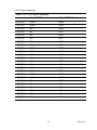
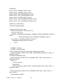
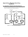
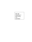
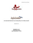
A.1 Appendix A Registry Searching Sequence
The following diagram demonstrates the sequence which the PCM-7130
follows to search for registry during bootup period.
Power On
SAFEMODE *1
No
Registry on CF
No
Yes
Yes
Image on
Flash Memory
No
Image on
CompactFlash
Image on
CompactFlash
Image on
CompactFlash
No
No
Image on
Flash Memory
Image on
Flash Memory
No
No
Yes
Yes
Yes
Registry on
Flash Memory
Yes
Boot
Failure*2
Boot Failure
Yes
Yes
Boot by Default
Registry
Boot by Registry
on CF
Boot Success
Boot Success
Boot by Registry
on Flash Memory
Figure A.1: A.1 Registry Searching Sequence
PCM-7130 User’s Manual
Yes
58
No
Appendix
B
Passive Matrix LCD
Display
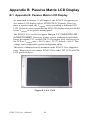
Appendix B Passive Matrix LCD Display
B.1 Appendix B Passive Matrix LCD Display
As mentioned in Section 1.3 of Chapter 1, the PCM-7130 supports passive matrix LCD display such as STN/DSTN LCD panels. However,
there is a power input, the Vcontrast, varies according to different STN
LCD. Therefore every system having STN LCD display must provide different Vcontrast to its specific mating panel.
The PCM-7130 is verified to support Nan-ya 7.4” VGA DSTN LCD
(LCBLDT163M9T). However, it takes a piece of adapter board which
boosts the normal 3.3V on the PCM-7130 to higher level, and serve it to
the LCD as Vcontrast max = 26.8 V, min = 22.3 V, default = 24.4 V. This
voltage can be adjusted by system configurator utility.
This piece of adapter board is mounted on the PCM-7130 as shipped to
users. With it users can connect PCM-7130 to either TFT LCD or DSTN
LCD specified above.
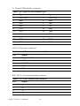
Figure B.1: 6.4” LCD
PCM-7130 User’s Manual
60
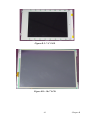
Figure B.2: 7.4” LCD
Figure B.3: 10.4” LCD
61
Chapter B
PCM-7130 User’s Manual
62
Index
A
L
T
audio 4
automatic data flow control 4
LCD interface 5
technical support iii
touchscreen 5
TV-out 5
C
M
memory 4
color depth 5
U
USB 4
D
dimensions 6
DIO 4
DRAM 2
E
Ethernet 4
F
FCC Class B iv
flash memory 2, 4
G
GPIO 4
I
Input voltage v
IrDA 4
J
Jumpers 11
O
operating humidity 5
operating system 4
operating temperature 5
V
P
W
Packing List iii
Part No. 2008L12600 ii
PCMCIA 4
Pin Assignments 60
PS/2 4
Watchdog Timer 57
watchdog timer 4
weight 6
Windows CE.NET 2
R
Rear view layout 10
resolution 5
RS-232 4
RS-485 4
S
SA-1110 2
Safety Instructions vi
Serial port 4
Side view layout 11
SM bus 4
Specifications 4
SSD 4
storage temperature 5
VGA controller 5