1
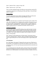
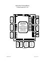
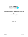
Troubleshooting Guide for Aquatrac Smart AS and Flex
Part 1
Sensors and Analog Signals
Alpha Release
July 28th, 2000
Alpha Release
Page 1 of 21
Preface
Welcome to the Aquatrac troubleshooting guide. This guide is intended to assist
you in determining the cause of problem with the operation of the Aquatrac Smart
AS and Smart Flex series of controllers.
We hope you find this guide useful. If you have any suggestions for
improvements, or other hints for troubleshooting, please contact us at
[email protected]
We will keep the most up to date copy of this manual on our web site at
www.aquatrac.com
Alpha Release
Page 2 of 21
Introduction and basic troubleshooting concepts
This guide is designed to assist you in finding the cause of problems with the
Aquatrac Smart AS and Flex series of controllers.
The process of troubleshooting is to determine where the problem is in a system
by eliminating possible causes of the problem until the failure is identified.
The guides are broken down by functional areas, inputs including sensors,
outputs, control functions, communications, and software. It is important to
remember that the problem you see may be caused by a problem somewhere
else in the controller.
SENSORS / INPUTS
It is very important to keep all low voltage wiring away from the high voltage
power wiring. Under no circumstance is low and high voltage wiring to share a
common conduit. Try to maintain as much distance as possible from the high
voltage and only cross at right angles. This will minimize noise and voltage
spikes being coupled into the low voltage section.
Failure to isolate the low voltage from high voltage will result in damage to
the controller.
ANALOG
The analog section deals with sensors that continuously vary. The unit will
convert the varying process into a number that is used to perform the control
functions.
Proper maintenance of probes and sensors is important to keep the readings as
accurate as possible. Maintenance schedules will vary from site to site and must
be determined based on past experience. When readings are drifting or appear
to be wrong, do not calibrate the sensor. Try to determine if something has
changed in the system to cause the drift. Contaminates can coat the probes
causing errors. Clean the probes before calibration and check if the readings
return to normal. Attempting to solve problems by calibrating seldom solves the
problem and just postpones proper troubleshooting.
Calibration Description
The controller uses the line formula for calculating the reading y=mx+b where y is
the reading, x is the raw AD value, m is the gain, b is the offset.
You can calibrate the controller using the TV remote, Trackster, or by a computer
running a terminal program. The built in sensors, terminals A through F, can be
calibrated using just one point. Most of the other sensors require two points. The
Alpha Release
Page 3 of 21
controller has a known value for the 0 point of the built in sensors, terminals A
through F.
Knowing two points the controller will determine the gain and offset. If the points
are the same an error will occur. The controller uses the standard line formulas to
calculate the gain and offset. If the reading did not change the controller will be
unable to find the correct gain and offset. (The denominator of the gain equation
will be ZERO)
(Value 1 – Value 2)
Gain = ------------------------------(raw AD 1 – raw AD 2)
Offset = (Value 1 * Gain) – raw AD 1
Trackster performs some slight of hand. If you attempt to calibrate most sensors
it will only ask for one point. Trackster uses the present gain and calculates a
new offset to correct the reading. (Well most of the time. The exception is
conductivity readings where Trackster holds the offset at zero and calculates a
new gain)
If you use a terminal program to calibrate the unit it will normally do a two-point
calibration for all calibrations. It is recommended that you use the TV remote or
Trackster for calibrations.
Prior to performing calibration look at the unit’s present gain and offset number
for the sensor in question. If they are outside the normal and expected ranges,
do a calibration with the TV remote not Trackster, or rest the gain and offset to
the factory default using the PA command.
To view the present gain and offset use the following procedures.
TV Remote
With the TV remote sign on to the unit using the Level 2 password.
(123456 default)
Press ENT twice, until the ‘ADJUST SETPOINTS?’ message appears.
Using the Channel Up and Down button scroll to the ‘CALIBRATE SENSORS?’
message.
Press ENT once.
Scroll to the sensor that you want to calibrate.
Press the PREV (CH) button.
Alpha Release
Page 4 of 21
The unit will display the gain and offset.
Press POWER button to back up.
Trackster
Connect to the unit.
Along the menu bar left click on the item labeled Controller.
Left click on the menu item View Controller Parameters.
Left click on the plus ‘+’ sign in the box next the item Analog Controls.
Left click on the sensor you are calibrating.
The right half of the display will change showing the present gain and offset of
the unit along with other information.
Terminal Program
Connect to the unit.
Log onto the unit with the configure level password.
Type PAx where x is the terminal that the sensor is connected.
(i.e. PAA to see the temperature sensor connected to terminals A+ and A-)
The unit will display the gain and offset for the indicated channel.
Resetting the Gain and Offset to Factory Default
To reset the gain and offset to factory default you must use a computer
connected to the controller. The following outlines the procedure for using
Trackster and a terminal program to reset the gain to the factory default.
Trackster
Note: You must connect at the configure level to change the gain.
Right click on any pump or relay output.
Select ‘Configure Control’
Press the following three keys simultaneously CTRL, ALT, and SHIFT.
Alpha Release
Page 5 of 21
The display should go to a terminal screen.
In the terminal window type PAx where x is the sensor’s terminals you wish to
change.
The display will show the present gain and offset.
To change the gain and offset type
PAx,,gain,offset
Where x is the sensor’s input terminals.
Important: You must have the two commas after the PAx.
The display will show the new gain and offset.
Left click on the X in the terminal screen boarder to exit.
Terminal Program
Connect to the unit and enter the configure level password.
Type PAx where x is the sensor’s terminals you wish to change.
The display will show the present gain and offset.
To change the gain and offset type
PAx,,gain,offset
Where x is the sensor’s input terminals.
Important: You must have the two commas after the PAx.
The display will show the new gain and offset.
Temperature
Calibration
The temperature sensors of the cooling and condensate conductivity probes
SHOULD NEVER be calibrated. The Smart Flex and AS probes use a solid state
temperature sensor which is guaranteed by the manufacturer to be accurate
within 1 degree centigrade.
Alpha Release
Page 6 of 21
If you must calibrate the temperature sensor the preferred solution is using the
PA command.
PAA, ,0.36,-459.4
This will calibrate the sensor with the manufacturing default values
If you calibrate using the system water ensure that the probe has been installed
and at temperature for a minimum of 10 minutes.
Gain and Offset
The factory gain is set for 0.36 offset for –459.4
Testing
If the controller displays an asterisk ‘*’, or Trackster extremely high temperature
readings, this indicates the temperature sensor is disconnected or the wiring is
open. Ensure that the wire and not the insulation from the wire is clamped by the
terminal block. If the cable was extended make sure the wiring is correct.
If the display shows a negative temperature, around –350 this indicates that the
temperature sensor is wired backwards. Again check the wiring.
The wiring of the cooling conductivity probe is:
Wire Color
White
Green
Red
Black
Terminal
A+ or B+
A- or BE+ or F+
E- or F-
Description
Positive lead of the temperature sensor
Negative lead of the temperature sensor
Positive lead of the conductivity sensor
Negative lead of the conductivity sensor
Using the CU command
The CU command displays the gain, offset, raw AD value, and other parameters
of the channel. To display the information for the temperature probe on channel
A type CUA enter. We are especially interested in the raw AD value. This is what
the controller is reading before calibration. By viewing this information we can
determine if the sensor is wired correctly and roughly what temperature the
sensor is seeing. If the sensor is correctly connected a reading of 1490 at 77
degrees F would be expected. The reading should change approximately 3 for
each degree F. At 80 degrees the reading will be 1499 and at 70 degrees 1469.
If the sensor is disconnected the raw AD value will be 4000. A backward sensor
will indicate around 290. A shorted sensor will have a raw AD value of 0.
Alpha Release
Page 7 of 21
Effects of temperature on other readings
A bad temperature measurement will cause errors in the cooling and condensate
conductivity readings. Temperature could also effect the pH measurement if
temperature compensation has been enabled.
Conductivity
The basic difference between the three conductivity circuits is the drive level. The
drive level is the amount of voltage being applied to the sensor to measure the
conductivity of the solution. Normally the drive levels are as follows:
Boiler
50mVac
Cooling
100mVac
Condensate 200mVac
The drive level can be seen and changed using the CR command.
Both Cooling and Condensate conductivity use temperature compensation,
Boiler conductivity is not temperature compensated.
Cooling Tower
Calibration
All conductivity calibrations should be single point and done close to the
operational point of the system. The farther the calibration is done from the
operating point the larger the likely error at the operating point.
The conductivity probe is susceptible to fouling, if oil or grease coat the probe the
reading will be lower then expected. This should be checked in new systems
where the possibility of oil and grease being present in the systems from the
manufacturing process is greatest.
Gain and Offset
The factory gain is 10 the offset is 0.
Testing
If the conductivity reading is inaccurate double-check the temperature reading.
Temperature has a large effect on the conductivity. Check the probe wiring. Note:
The red and black wires are interchangeable, there is no polarity that must be
maintained.
Alpha Release
Page 8 of 21
If the reading is 0 check that the probe is connected and in water, also determine
that there are no opens in the wiring to the probe. Ensure that the wire, and not
the insulation, from the wire is clamped by the terminal block.
An extremely large conductivity is an indication of a short in the wiring to the
probe. Check the wiring from the probe to the controller.
Troubleshooting with Gain and Offset readings
For normal cooling applications the gain should be between 8 and 13. If the gain
is close to zero check for shorts in the wiring, if the gain is extremely large check
for an open wire. The offset should be zero, if you did a two point calibration then
the offset should be less then 20.
Using the CU command
The CU command will show the conductivity reading before the application of the
gain and offset. A raw AD value of 100 is approximately equal to 1000 uS at 25
degrees C. If there is a short the CU command will show a raw AD value of 4000.
If the wiring to the probe is open the CU command will show a raw AD value near
0.
Note: A 1K ohm resistor connected to the red and black terminals of the terminal
block is approximately equal to 1000 uS at 25 degrees C, and will display a raw
AD value of approximately 100.
Boiler
The important item to remember with boiler application is the conductivity is only
updated after a measurement cycle. You can force a measurement cycle by
clearing alarms with the TV remote, Trackster, or by typing CA$ enter in a
terminal program. On initial power up a boiler conductivity will display an asterisk
‘*’. The asterisk will remain until the first measurement cycle is completed.
Calibration
During calibration a measurement cycle will be initiated and must be completed
for the calibration to succeed.
Refer to the cooling conductivity section for more information on calibration.
Gain and Offset
The factory gain is 10 and offset is 0.
Alpha Release
Page 9 of 21
Testing
Temperature compensation is not used on boiler conductivity. All other items in
the cooling conductivity section apply.
Troubleshooting with Gain and Offset readings
For normal boiler applications the gain be between 8 and 13. If the gain is close
to zero check for shorts in the wiring, if the gain is extremely large check for an
open wire. The offset should be zero, if you did a two point calibration then the
offset should be less then 20.
Using the CU command
The CU command will show the conductivity reading before the application of the
gain and offset. A raw AD value of 100 is approximately equal to 1000 uS. If
there is a short the CU command will show a raw AD value of 4000. If the wiring
to the probe is open the CU command will show a raw AD value near 0.
Note: A 1K ohm resistor connected to the red and black terminals of the terminal
block is approximately equal to 500 uS, and will display an approximate raw AD
value of 50.
Condensate
Condensate operation is identical to the cooling conductivity section. Please refer
to the cooling conductivity section for more information.
Note: A 1K ohm resistor connected to the red and black terminals of the terminal
block is approximately equal to 2000 uS, and will display an approximate raw AD
value of 200.
Add-on Board
Calibration
The calibration of an add-on board is the same as outlined above. The boards
drive level is factory adjusted prior to being shipped for the application. If it is a
boiler sensor it will be set to 50mV, cooling or raw water / make up 100mV,
condensate 200mV.
Gain and Offset
Factory gain is 10 and offset is 0.
Alpha Release
Page 10 of 21
Testing and Troubleshooting
Check the wiring from the main board to the add-on card. The factory color code
for wiring on the main board is P = red, + = black, and - = white. The wiring on
the card is +12 = red, TDS = black, GND = white.
For cooling and condensate applications there should be no jumpers installed on
the add-on card. For boiler applications there should be a jumper at the Temp
terminals.
If the unit is reading near zero check that the jumper on the main board
associated with the input terminals is removed. This jumper should not be
installed with the add-on board.
Refer to the appropriate conductivity troubleshooting section for more
information. Placing a 1K ohm resistor in place of the probe will have the same
response as described in the tower, boiler, condensate sections.
pH
For pH measurement to work properly the solution ground and controller ground
must be tied to earth ground.
pH cannot be measured in sample streams near or below 0 degrees C with the
standard probes.
The pH probes are identified with a blue sleeve near the end of the cable. The
standard pH probe body is blue.
Cooling Tower
Calibration
pH can be calibrated with standard solutions or single pointed at the system pH
level. If you are removing the probe from the pipe header to calibrate, allow the
probe to stand in the solution at least 5 minutes to stabilize. Two-point calibration
is not recommended.
Gain and Offset
The factory gain is 0.017 and the factory offset is 7.0
Alpha Release
Page 11 of 21
Testing
If the wiring of the probe is open the pH display will drift to an extreme reading,
either positive or negative. If the pH is flat lined at 7 pH this is an indication of a
short or that the black paper covering is connected to the + input of the pH
terminal. This paper covering is slightly conductive and will short out the pH
reading.
The center conductor, normally insulated in a clear plastic, should be connected
to the + terminal. The shield, normally the large silver wire, should be connected
to the – input. If the wires are connected backwards the pH will be flipped around
the 7 pH point. If the actual reading is 6 pH the unit will display a reading of 8 pH.
This is indicated by a negative gain if the unit was two-point calibrated with this
wiring in a solution other then 7 pH buffer.
Troubleshooting with Gain and Offset readings
If after a calibration the offset is less then 6 or greater then 8 then recalibrate with
a 7 pH buffer. If after calibrating with the 7 pH buffer the offset is less then 6 or
greater then 8 this is an indication that the probe is depleted and must be
replaced.
Note: This is only valid for the factory default gain of 0.017.
Using the CU command
A raw AD value greater then 500 or less then –500 is an indication of an open in
the probe wiring.
The raw AD value can be converted to a pH reading as follows:
0 = 7 pH
For every 57 this is a change of 1 pH. If the reading is 114 this would indicate a
reading of 10 pH. If the reading is –114 this would indicate a reading of 5 pH.
Note: Connecting a 1K ohm resistor in place of the probe at the measurement
terminals should indicate a pH of approximately 7 pH. The raw AD value should
be 0.
Alpha Release
Page 12 of 21
Boiler Condensate
It is extremely important to ground the fitting of the condensate pH probe.
Condensate has a very low conductivity and it is possible for static charges to
build up on the probe and give false readings.
If your condensate is of a very high quality, less then 20 uS, it will be
extremely difficult to measure the pH of the condensate.
Please contact Aquatrac Instruments for more information.
Calibration
The condensate pH probe is double junction and takes much longer to respond
then a standard probe. When you calibrate allow the probe to stabilize for at least
10 minutes in the solution.
Gain and Offset
The factory gain is 0.017 and the factory offset is 7.0
Testing
Testing and troubleshooting is the same as the cooling pH section. Please refer
to the cooling pH section.
Flat Face
The Flat Faced pH probe is a double junction probe. It will take up to twice as
long to stabilize as a standard probe. By examining the sensing element you can
identify the probe, if it is a glass dome it is a pH electrode and not an ORP probe.
All other items are the same as the cooling pH probe. Please refer to the cooling
pH section for calibration and troubleshooting guidelines.
Add-on Board
The add-on board behaves the same as the standard pH inputs. The factory
wiring of the board is P = red, + = black, and - = white. This is identical both at
the main board and on the add-on board.
On the pH add-on board there should be jumpers present at the S terminals and
the N terminals.
If the unit is reading near 7 pH check that the jumper on the main board
associated with the input terminals is removed. This jumper should not be
installed with the add-on board.
Alpha Release
Page 13 of 21
ORP
ORP like pH requires that the piping solution ground and the controller ground be
connected to earth ground.
The ORP probe is identified with a red sleeve near the end of the cable. The
body of the standard ORP probe is red.
Cooling Tower
Calibration
ORP should never be calibrated. The output of an ORP probe is a relative
indication of the oxidizing or reducing tendencies of the solution.
Gain and Offset
The factory gain is –1 and the offset is 0
Testing
If the reading is drifting insure that the grounds to both the solution and controller
are intact and are connected to earth ground.
If the reading is drifting to an extreme this is an indication that the probe wiring is
open. If the unit is flat lines at 0 this is an indication of a short in the probe wiring
The center conductor, normally insulated in a clear plastic, should be connected
to the + terminal. The shield, normally the large silver wire, should be connected
to the – input. If the wires are connected backwards the ORP will display
negative readings when positive readings are expected. This is also indicated by
a positive gain if the unit was two-point calibrated with this wiring.
Troubleshooting with Gain and Offset readings
An extreme offset is an indication of an open wire. A large gain is an indication of
a short in the wiring. A positive gain is an indication of reversed wiring.
Using the CU Command
If the raw AD value is greater then 1000 or less then –1000 this is an indication of
an open in the probe wiring. The controller will show the raw AD value * -1 as the
ORP reading.
Alpha Release
Page 14 of 21
Note: Connecting a 1K ohm resistor in place of the probe at the measurement
terminals should indicate a ORP of approximately 0. The raw AD value should be
0.
Flat Face
The Flat Faced ORP probe is a double junction probe. It will take up to twice as
long to stabilize as a standard probe. By examining the sensing element you can
identify the probe, if it has a ceramic look then it is an ORP probe.
All other items are the same as the cooling ORP probe. Please refer to the
cooling ORP section for calibration, and troubleshooting guidelines.
Add-on Board
The add-on board behaves the same as the standard ORP inputs. Please refer
to the ORP Cooling Tower section for calibration and testing instructions.
The factory wiring of the board is P = red, + = black, and - = white. This is
identical both at the main board and on the add-on board.
On the ORP add-on board there should be jumpers present at the F terminals
and the N terminals.
If the unit is reading near 0 check that the jumper on the main board associated
with the input terminals is removed. This jumper should not be installed with the
add-on board.
Corrosion
It is very important to keep foreign material off the corrosion rate probes. Any
material collecting on the probes will cause false readings and excessive
alarming. It is highly recommended that a filter be installed upstream of the
probes.
After the initial installation of the corrosion probe, or after replacing the probe
tips, the readings will be high for the first few days. This is a normal response
and the reading should drop to the expected range.
Under no circumstances are the probes to be cleaned with an abrasive or
file. This will change the relationship between the areas of the probes causing
errors in the readings.
Calibration
The corrosion board cannot be calibrated.
Alpha Release
Page 15 of 21
Testing
The factory wiring of the corrosion board is P = red, + = black, and - = white. This
is identical both at the main board and on the corrosion board.
A jumper should be installed in the RUN position. Never use the CAL position.
Note: Placing a 1K ohm resistor in place of the probe should indicate the
following approximate readings.
Anodic = 10
Cathodic = -10
Pitting = 0
Rate = 5
This assumes the sensor is configured for carbon steel.
Effects of conductivity on readings
If the conductivity of the water is less then 500 uS the corrosion rate
measurement will be in error. The conductivity must be greater then 500 uS for
proper operation.
Level Sensors
For the level sensor to work properly the 4-20 mA jumper associated with the
terminals must be installed.
Calibration
Level sensors must be calibrated using two points. The first point should be the 0
point. Place the sensor next to the drum and enter 0 for the first point in the
calibration sequence. When the controller asks for the second point, place the
sensor in a full, or partially full, drum and enter the volume of chemical in the
drum.
You can also perform an ‘Ideal Calibration’ which is described below.
Ideal Calibration
The ‘Ideal Calibration’ can only be performed with a computer connected to the
controller.
You can calculate the gain and offset for the level sensor using the following
information and formula. The value at 4 mA should be 0, an empty container. The
value at 20 mA should equal the volume of the container i.e. 55 gallons. To find
the gain and offset use the following formulas.
Alpha Release
Page 16 of 21
Gain = (Value at 20 mA – Value at 4 mA) / 800
Offset = Value at 4 mA – (200 * Gain)
Once you have calculated the gain and offset you can enter them using the PA
command as described in the ‘Resetting the Gain and Offset to Factory Default’
section on page 5.
Gain and Offset
To find the approximate correct values for the gain and offset you will need to
perform the calculation described in the Ideal Calibration section
Testing
The + wire from the sensor is connected to the P terminal on the controller. The
other wire is connected to the + terminal on the controller. If the wiring is wrong
or there is in open in the wiring the LED will be off. Note: The LED will be on if
the second wire is connected to the – terminal, but the controller could show a
negative reading and the CU command will indicate a raw AD value of 0.
Using the CU command
A raw AD value between 0 and 200 indicates a loop value less then 4 mA, this
would indicate a need to check the wiring of the level sensor not the controller.
If the reading is 4000 this indicates that the jumper associated with the input is
not installed. Unlike add-on boards this jumper must be installed for the level
sensor to work properly.
Note: The input can be checked with a 1K ohm resistor. Connect the resistor
from the ‘P’ terminal to the ‘+’ terminal. The CU command should show a raw AD
value of approximately 600, the unit should display a level of approximately half
full.
4-20 mA Inputs
Any of the inputs in the range of G through N can be used as a 4-20mA input to
the controller. The controller has a 49.9 ohm load resistor on the loop. If you are
using the input as a 4-20 mA input the jumper associated with the terminals must
be installed.
If you are sharing the loop with other devices, all other device must have floating
inputs and the Aquatrac controller must be the last item in the loop. If the other
devices are not isolated please use an isolation transmitter between the devices.
Alpha Release
Page 17 of 21
Calibration
All 4-20mA signals require a two-point calibration. This allows the controller to
determine the 4 and 20 mA levels presented by the external device. An ‘Ideal
Calibration’ can be entered using the PA command, see the ‘Ideal Calibration’
section.
Ideal Calibration
An ‘Ideal Calibration’ can only be performed with a computer connected to the
controller.
You can calculate the gain and offset for the device you are connecting to the
controller. All you need to know is what the value of measurement = 4mA and
what value = 20mA. This can be found in the users manual of the instrument. To
find the gain and offset use the following formulas.
Gain = (Value at 20 mA – Value at 4 mA) / 800
Offset = Value at 4 mA – (200 * Gain)
Note: Depending on the measurement the gains and offsets can be either
positive or negative quantities.
Once you have calculated the gain and offset you can enter them using the PA
command as described in the ‘Resetting the Gain and Offset to Factory Default’
section on page 5.
Gain and Offset
The range of the external device determines the gain and offset. See the ‘Ideal
Calibration’ section
Testing
Using the CU command
A raw AD value between 0 and 200 indicates a loop value less then 4 mA, a
reading greater then 1000 indicates a loop value greater then 20mA. This would
indicate a need to check the calibration of the external device not the controller.
On some transmitters and instruments a reading outside the normal range or a
reading stuck at either 4 or 20 mA is and indication of a sensor failure. Again,
please refer to the instructions supplied with the external device. A negative
reading is an indication that the wiring is reversed.
Alpha Release
Page 18 of 21
If the reading is 4000 this indicates that the jumper associated with the input is
not installed. Unlike add-on boards this jumper must be installed for the 4-20 mA
input to work properly.
Note: The input can be check with a 1K ohm resistor. Connect the resistor from
the ‘P’ terminal to the ‘+’ terminal. The CU command should show a raw AD
value of approximately 600.
Alpha Release
Page 19 of 21
Smart Flex Terminal Blocks
(4-20mA Jumpers LG – LN)
G B A
Gnd
DIM
Sensor
Inputs
'K'
thru
'N'
Liquid
Level.
Xtra
TDS
Sensor
Inputs
'G'
thru
'J'
Liquid
Level,
Xtra
Sensors.
...
NN+
NP
MM+
MP
LL+
LP
KK+
KP
JJ+
JP
II+
IP
HH+
HP
GG+
GP
IR REMOTE
RS232
MODEM
ADAD+
NETWORK
AR-L
AR-N
R8
R7
R6
LN
LM
LL
LK
Inside Controller
enclosure door
Cabling Locations
R5
SFMAN1.CDR
Warning:
Maintain the separation
between AC power and
sensor and communication
cabling by using the
adjustable cable
tie-downs on the
aluminum backplate
LJ
LI
LH
R3
R2
R1
N8
NO8
N7
NO7
NC7
N6
NO6
NC6
N5
NO5
N4
NO4
N3
NO3
NC3
N2
NO2
NC2
N1
NO1
N
LF
G
N
L
Dry
& Hot
Alarms
Relays
5 to 8
Pumps
Valves
Solenoids
Relays
1 to 4
Pumps
Valves
Solenoids
AC
to
Modem
AC
Power
IN
OFF ON
POWER
LG
pH Temp Cond. pH Temp Cond.
C+ C- A+ A- E+ E- D+ D- B+ B- F+ F-
pH/ORP
Temp
TDS,
Sensors
'A','C'
& 'E'
R4
CONTROL RELAYS
Status
Switches
'U'
thru
'Z'
Flow
Thermal.
Vibrate,
Limit
DISPLAY
+12
ZZ+
YY+
XX+
WW+
VV+
UU+
pH/ORP
Temp
TDS,
Sensors
'B','D'
& 'F'
Meter-O Meter-P Meter-Q
OP O+ O- PP P+ P- QP Q+ Q-
Watermeters
'O', 'P'
& 'Q'
Contact
Head,
Turbine
or
Paddlewheel
Meter-R Meter-S Meter-T
OR R+ R- SP S+ S- TP T+ T-
Watermeters
'R', 'S'
& 'T'
Contact
Head,
Turbine
or
Paddlewheel
SFMAN9.CDR
Alpha Release
Page 20 of 21
Smart AS Terminal Blocks
(4-20mA Jumpers LG – LJ)
Alpha Release
Page 21 of 21