1
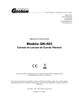
Instruction Manual
Model 1280
(Model A6)
Borehole Extensometer
No part of this instruction manual may be reproduced, by any means, without the written consent of Geokon, Inc.
The information contained herein is believed to be accurate and reliable. However, Geokon, Inc. assumes no
responsibility for errors, omissions or misinterpretation. The information herein is subject to change without
notification.
Copyright © 2002, 2006 by Geokon, Inc.
REV B 1/06
Warranty Statement
Geokon, Inc. warrants its products to be free of defects in materials and workmanship, under normal use and
service for a period of 13 months from date of purchase. If the unit should malfunction, it must be returned to
the factory for evaluation, freight prepaid. Upon examination by Geokon, if the unit is found to be defective,
it will be repaired or replaced at no charge. However, the WARRANTY is VOID if the unit shows evidence
of having been tampered with or shows evidence of being damaged as a result of excessive corrosion or
current, heat, moisture or vibration, improper specification, misapplication, misuse or other operating
conditions outside of Geokon's control. Components which wear or which are damaged by misuse are not
warranted. This includes fuses and batteries.
Geokon manufactures scientific instruments whose misuse is potentially dangerous. The instruments are
intended to be installed and used only by qualified personnel. There are no warranties except as stated herein.
There are no other warranties, expressed or implied, including but not limited to the implied warranties of
merchantability and of fitness for a particular purpose. Geokon, Inc. is not responsible for any damages or
losses caused to other equipment, whether direct, indirect, incidental, special or consequential which the
purchaser may experience as a result of the installation or use of the product. The buyer's sole remedy for any
breach of this agreement by Geokon, Inc. or any breach of any warranty by Geokon, Inc. shall not exceed the
purchase price paid by the purchaser to Geokon, Inc. for the unit or units, or equipment directly affected by
such breach. Under no circumstances will Geokon reimburse the claimant for loss incurred in removing
and/or reinstalling equipment.
Every precaution for accuracy has been taken in the preparation of manuals and/or software,
however, Geokon, Inc. neither assumes responsibility for any omissions or errors that may appear
nor assumes liability for any damages or losses that result from the use of the products in
accordance with the information contained in the manual or software.
TABLE of CONTENTS
1. INTRODUCTION ..........................................................................................................................................................1
2. PRELIMINARY REQUIREMENTS ..........................................................................................................................1
3. INSTALLATION...........................................................................................................................................................3
4. ADJUSTING ANCHOR DEPTHS..............................................................................................................................6
5. ELECTRONIC READOUT - VIBRATING WIRE DISPLACEMENT TRANSDUCERS...................................7
6. TAKING READINGS ...................................................................................................................................................9
7. DATA ANALYSIS.....................................................................................................................................................10
8.
TROUBLESHOOTING ............................................................................................................................................13
APPENDIX 1
WIRING CHARTS FOR VIBRATING WIRE TRANSDUCERS. .................................................14
APPENDIX 2.
USING A PULL-IN ANCHOR IN DEEP BOREHOLES .........................................................17
1
1. INTRODUCTION
The Model A6 Multiple Position Borehole Extensometer, (MPBX), is made up of three or four basic
components:
•
Borehole anchors, these may be either groutable or hydraulic types. The groutable type is usually
recommended for downward directed boreholes or for holes that must remain sealed. Special
equipment will be required for grouting boreholes directed upwards. Hydraulic anchors can be used
anywhere and are particularly suited for use in upward directed boreholes. Usually the number of
anchors lies between one and six.
•
Connecting rods and tubing, the standard rod is made from ¼ inch fiberglass encased in ½ inch
polyethylene tubing for borehole lengths less than 30 meters, or ½ inch nylon tubing for borehole
depths greater than 30 meters. The flexibility of the rods and tubing allows the extensometer to be
pre-assembled and coiled at the factory for shipment to the job-site where it can be uncoiled and
inserted into the borehole. This greatly speeds up the installation process.
•
Extensometer head assembly, various styles are available: the head may be designed for recessing
into an enlarged section of the borehole or it may have a flange for mounting to a standpipe grouted
into the mouth of the borehole. Provision may be made for manual or electronic readout or for both.
Manual readout is by a 50mm range dial indicator.
•
Electronic displacement transducers, (optional), the standard transducer is the model 4450
vibrating wire displacement transducer with ranges of 25, 50, or 100 mm. Linear potentiometers are
also available.
2. PRELIMINARY REQUIREMENTS
2.1 Borehole Requirements
The Model A6 is designed to fit 75mm (3 inch) or larger diameter boreholes. The mouth of the borehole may
be cased with a 2½-inch standpipe or enlarged to take a 3-inch or 3½-inch standpipe or it may be left free.
Boreholes should be free of debris and drilled slightly longer, (60cm, (2ft)), than the deepest anchor.
2.2 Anchor Spacing
Anchor spacing is sometimes dictated by geologic features and by the size and geometry of the rock mass
being monitored. Drill cores can be inspected to reveal zones and planes of weakness, which would suggest
appropriate anchor locations. At least one anchor, usually the deepest anchor, should be located in stable
ground so that it can serve as a non-moving point of reference for the rest of the anchors. For extensometers
installed in tunnels the deepest anchor should be located at least one tunnel diameter, and preferably nearer
two tunnel diameters, away from the tunnel opening.
2.3 Instrument Head Protection
The instrument head should be protected from damage. This may require recessing the instrument head
inside the borehole to avoid blasting damage or, in exposed locations the construction of a protective
enclosure, to ward against falling objects, moving equipment and vandalism.
MPBX heads installed downwards from street level are best contained within manholes with access covers.
The manhole should be large enough to accommodate the instrument head and any datalogger that may be
in use. The minimum size of manhole is 300mm (12 Inch). A better size is 550mm (22inch) diameter. Covers
may be equipped with a locking device. The manhole should be provided with a drain so that it cannot
become filled with rainwater.
Heads may be equipped with a flange to engage the flange on top of any standpipe grouted into the mouth of
the borehole. This arrangement works well with groutable anchors. Where hydraulic anchors are in use the
instrument head comes equipped with its own hydraulic anchor so standpipes and flanges are not always
required.
2
2.4 List of Installation Tools Required
Note: Installation Tool kits may be purchased as an accessory. They may include the following:
1. Two pair of Vise Grips
2. Adjustable wrenches
3. Screw Drivers
4. Allen Wrenches
5. Hacksaw
6. Files
7. Tape measure
8. Marking Pens
9. Loctite adhesive
10. PVC Cement
11. PVC Primer
12. Hydraulic hand-pump with pressure gage and fittings (Hydraulic Anchors).
13. Portland cement (N0 2) (Groutable Anchors).
14. Quick Setting Cement
15. Grout Tube and fittings (Groutable Anchors).
16. Grout Pump (Groutable Anchors).
17. Grout Plate (Normally Supplied)
18. Water (for flushing and grouting).
19. Sharp Knife
20. Tape (Filament)
21. Tape Masking (Groutable Anchors)
22. Tape (Duct)
23. Spare parts –Swagelok Connectors and spare ferrules, O-rings, setscrews, bolts, screws, etc.
(Normally shipped with the extensometer parts).
3
3. INSTALLATION
3.1 Standard Groutable System with Manual Readout – Downward Directed Boreholes.
A typical system is shown in figure 1
Figure 1
3.1.1
Normally, the MPBX is shipped pre-assembled and coiled for shipment. Care should be taken when
removing the tape holding the coils. Release one coil at a time and keep a tight grip on the rest of
the coils so that they cannot suddenly break free and uncoil violently. Do not cut the tapes bundling
the rod/tubes together. Lay out the MPBX on a flat dry surface, as close to the borehole as possible.
3.1.2
If a Standpipe is to be installed it should be assembled now. Glue the Coupling, (or Flange), to the
standpipe using PVC purple primer and cement. Apply quick-setting cement on the outside of the
standpipe and insert into the borehole to the desired depth. Hold in place until the cement hardens,
using wooden wedges or sackcloth soaked in quick-setting cement, as required.
3.1.3
If the anchor depths need to be adjusted from those set at the factory see section 4.
3.1.4
The MPBX is shipped with the Grout Tube coiled separately. It should now be uncoiled and pushed
through the hole on the center of the Grout Plate and attached lightly to the deepest anchor only,
using enough masking tape so that it will not scrape off when the MPBX is pushed into the hole but
not so much that it cannot be broken free when grouting commences.
3.1.5
Slide the MPBX into the borehole until the Tube Mount is about to enter the coupling (or flange), be
careful not to bend the MPBX in too tight a radius. Add PVC cement to the outside of the Tube Mount
where it seats inside the standpipe coupling. Push the Tube Mount inside the coupling and allow the
PVC cement to harden. (If flanges are used instead of couplings, glue the tube mount to the tube
mount flange, then bolt this flange to the flange on the standpipe using the bolts supplied).
3.1.6
Connect the grout pipe to a grout pump and pump a little water through the grout line to lubricate it.
Mix up a batch of cement grout with the consistency of pancake batter. Use Portland No. 2 cement
mixed with water in approximately 1:1 mixture. Do not use any sand. Pump the grout into the
borehole while slowly pulling the grout tube from the borehole. If the grout tube is to be used again
flush it now with water.
3.1.7
After the grout has set up, remove the grout plate and replace it with the Reference Surface. Be
careful to match the numbers stamped on the Tube Mount with those on the Reference Surface. Take
initial readings with the dial indicator and record. Screw on the Protective Pipe Cap to protect the
Reference Surface.
4
3.2 Standard Groutable System with Manual Readout – Upward Directed Boreholes
Upward directed boreholes require special grouting techniques.
3.2.1
Normally, the MPBX is shipped complete and pre-assembled and coiled for shipment. Care should
be taken when removing the tape holding the coils. Release one coil at a time and keep a tight
grip on the rest of the coils so that they cannot suddenly break free and uncoil violently. Do not cut
the tapes bundling the rod/tubes together. Lay out the MPBX on a flat dry surface, as close to the
borehole as possible.
3.2.2
The standpipe should be assembled first. Glue the coupling, (or flange), to the standpipe using PVC
purple primer and cement. Apply quick-setting cement on the outside of the standpipe and insert into
the borehole to the desired depth. Use plenty of cement to ensure a grout-tight seal around the
standpipe. Hold in place until the cement hardens, using wooden wedges or sackcloth soaked in
quick-setting cement, as required.
3.2.3
If the anchor depths need to be adjusted from those set at the factory see section 4.
3.2.4
Using Figure 2 as a guide, screw the down-hole grout pipe, (7), into the back of the Tube Mount,
screw the external grout pipe, (8), into the front of the Tube Mount, thread the vent tube, (6),
through these two pipes and tape to the deepest borehole anchor so that it protrudes beyond the
anchor by a distance of about 30 centimeters. Now slide the Valve/Tee assembly, (1thru 5), over the
vent tube and screw onto the external grout tube. Tighten the Swagelok fitting, (1), onto the vent tube
Figure 2
3.2.5
Push the entire assembly into the borehole until the head assembly is about to enter the standpipe,
be careful not to bend the MPBX in too tight a radius. Add PVC cement to the outside of the head
where it seats inside the standpipe coupling. Push the head inside the coupling and allow the PVC
cement to harden. (If bolted flanges are used instead of cemented couplings, apply RTV sealant to
one of the flange faces then bolt the flange on the head to the flange on the standpipe using the bolts
supplied).
3.2.6
Because of the high pressures involved the grouting must be done in two stages: The first stage is to
grout the first meter and a half, (5ft), of the borehole so as to form a plug, which can seal the borehole
and permit the rest of the hole to be grouted. Calculate the amount of grout required to do this.
Connect the grout pipe to the gate valve and to a grout pump. Mix up the calculated amount of
cement grout with the consistency of pancake batter. (Use Portland No 2 cement and water in about
a 1:1 mix). Do not use any sand. With the valve open, pump the measured amount of grout into the
borehole. With the valve still open, remove the grout pipe and allow any excess grout, above the level
of the end of the down-hole grout pipe inside the borehole, to drain away. Reconnect a water supply
to the Valve/Tee assembly and pump a few liters (gallons) of water into the borehole then disconnect
the water supply and allow the water to flow back out of the hole and flush the system ready for the
second stage of grouting. Allow the grout 24 hours to set up.
5
3.2.7
After the first-stage grout plug has set up, reconnect the grout pump and pump grout until grout is
seen exiting the vent tube. (Excessive grout pressures should be avoided since there is a danger of
blowing out the plug). When grout is seen issuing from the vent line stop pumping, close the Gate
Valve, and disconnect the pump. (In fractured ground there may be some leakage into the fractures
causing the top anchor to become un-grouted. To ward against this, the pump can be left connected
and grouting can be continued at intervals until, on recommencing the pumping, the grout is seen to
flow immediately from the vent tube at which point the grout column is probably complete and
covering the top anchor.)
3.2.8
After allowing sufficient time for the grout to harden, the grout pipe Valve/Tee assembly should be
unscrewed from the MPBX head, or cut off flush with the MPBX head, and discarded. Remove the
grout plate and replace it with the Reference Surface. Take initial readings with the dial indicator and
record. Screw on the Protective Pipe Cap to protect the Reference Surface.
3.3 Standard Hydraulic System with Manual Readout
Hydraulic anchors may be of the Bladder type or of the Borros type.
3.3.1
A standpipe, made from steel or PVC pipe, is not usually required except where the mouth of the
borehole is fractured, oversize or irregular. If a standpipe is needed to stabilize the borehole collar,
then the mouth of the borehole may have to be enlarged so that standpipe used can have at least the
same I.D as the rest of the borehole. Apply quick-setting cement on the outside of the standpipe and
insert into the borehole to the desired depth. Hold in place until the cement hardens, using wooden
wedges or sackcloth soaked in quick-setting cement, as required.
3.3.2
Normally, the MPBX is shipped complete and pre-assembled and coiled for shipment. Care should
be taken when removing the tape holding the coils. Release one coil at a time and keep a tight
grip on the rest of the coils so that they cannot suddenly break free and uncoil violently. Lay out the
MPBX on a flat dry surface, as close to the borehole as possible.
3.3.3
If the anchor depths need to be adjusted from those set at the factory see section 4.
3.3.4
Push the MPBX into the borehole until the hydraulic anchor on the head assembly is well inside the
borehole, (or inside the standpipe if one is used), be careful not to bend the MPBX in too tight a
radius. For deep boreholes, requiring a pull-in anchor, see Additional instructions in Appendix 2.
3.3.5
The hydraulic anchors are expanded beginning with the deepest anchor. (Anchors are numbered so
that the shallowest anchor is number one. Thus the deepest anchor will have the highest number). If
the end of the hydraulic tubing is plugged by a nail, cut off about 20mm of the tubing and attach one
of the 1/8 inch Swagelok tube fittings. When tightening Swagelok fittings use a wrench to tighten the
nut 1¼ turns beyond finger tight; tighter than this can pinch the tube shut. If the end of the tube is
already sealed by a Swagelok tube-fitting, remove the cap. Connect the hydraulic line to the handpump filled with hydraulic oil and inflate the cells. Watch the pressure gage while pumping and be
sure never to exceed a pressure of 10 MPa (1400 psi). More pressure than this can burst the
tubing. (It takes about 5 Mpa to begin to inflate the copper bladder on the Bladder type anchor or to
drive out the prongs on the Borros type anchor). Continue pumping until the anchor pressure holds
steady at about 9 MPa (1300psi). Disconnect the hydraulic pump – the check valve at the anchor will
maintain the anchor pressure. (Note: tests have shown that the anchor will continue to hold even if
the anchor pressure drops to zero).
3.3.6
Repeat this process for the rest of the anchors, in descending numerical order, and for the anchor on
the MPBX Head.
3.3.7
Take initial readings with the dial indicator and record. Screw on the Protective Pipe Cap to protect
the Reference Surface
6
4.
ADJUSTING ANCHOR DEPTHS
Occasionally, unforeseen site conditions may require the anchor depths to be adjusted. This will require
the rods and tubes to be either lengthened or shortened.
4.1 Shortening the rods and tubes – groutable and hydraulic anchors
Figure 3
4.2
4.1.1
With the MPBX uncoiled on a flat surface, measure the amount to be shortened, from the hose
barb on the anchor along the ½ inch O.D. poly tubing then mark the tubing. Next, with a sharp
knife, cut only the tubing at this mark. Do not cut the fiberglass rod.
4.1.2
Loosen the Swagelok Connector on the outer end of the anchor and remove the nut and
ferrules (olives) from around the fiberglass rod.
4.1.3
Pull the anchor and the piece of tubing already cut off, from off the fiberglass rod. Remove this
piece of tubing from the hose barb and discard.
4.1.4
Slide the anchor back over the fiberglass rod and reattach the poly tubing to the hose barb. (If
necessary, warm the poly-tube to make this easier). Slide a new set of ferrules and nut over the
fiberglass rod and tighten to the Swagelock fitting on the anchor. Make sure that the two parts of
the ferrule are correctly oriented and positioned.
4.1.5
With a hacksaw saw off the excess fiberglass rod protruding from the anchor.
Lengthening the rods and tubes – groutable and hydraulic anchors
This procedure requires the use of special factory supplied extension kit, which includes fiberglass rod
extensions, of the correct length, poly tubing and barbed tube fittings.
4.2.1
With the MPBX uncoiled on a flat surface remove the grout plate (or Reference Surface) from the
MPBX head, loosen the Swagelok fitting on the outer end of the anchor and remove the nut and
ferrules (olives) and then push the fiberglass rod through the anchor until the other end protrudes
from the MPBX head.
4.2.2
Disconnect the anchor from the poly tube at the barb fitting on the anchor, (cut the tubing if
necessary). Connect the correctly measured length of extension poly tube that will position the
anchor at its new depth, to the rest of the tubing using a barb/barb fitting, then reconnect this
extended tubing to the barb fitting on the anchor. Warming the poly tube so that it softens will
facilitate the connection
7
4.2.3
Connect the fiberglass extension rod to the threaded end of the fiberglass rod at the MPBX head
end. Use Locktite on the threads. Push the extension rod into the MPBX head until the tip is
positioned at the same depth as before. Slide new ferrules and nut onto the fiberglass rod and
then tighten the Swagelok fitting on the anchor so that it grips the rod.
4.2.4
Usually there is enough extra hydraulic tubing supplied with the hydraulic anchors that the end of
the hydraulic tubing will remain accessible. If this is not the case then the hydraulic tubing must
be extended using a 1/8 inch Swagelok tube/tube connector.
4.2.5
Replace either the Grout Plate or the Reference Surface.
5. ELECTRONIC READOUT - VIBRATING WIRE DISPLACEMENT
TRANSDUCERS
Electronic readout is usually accomplished by means of transducers and a transducer housing that are
assembled and bolted to the MPBX head after the initial installation of the anchors and head has been
performed. There are many variations and specific and detailed instructions are supplied with each
extensometer. The following instructions apply, in a general way only, to the two main standard designs: one
that permits electronic readout only and one that permits both electronic and manual readout. These general
instructions will serve as an explanation for the more detailed instruction and why they are necessary.
5.1 Electronic Readout Only
A typical MPBX head assembly, designed to accept vibrating wire displacement transducers is shown in
figure 4.
Figure 4
5.1.1
The Guide Tubes provide a space in which the transducers are located. They may be shipped
separately from the coiled fiberglass rods and tubes. If shipped separately then they must be first
attached, first to the Tube Mount by threading and/or gluing, and then attached to the uncoiled
tubing with Hose Barbs after a specified amount of the uncoiled tubing has been removed. The
amount to be removed is such that when the fiberglass rod is connected to the transducer the
transducer will be correctly positioned within the Guide Tube. Numbers stamped on the Tube
Mount ensure that the correct anchor is connected to the corresponding Guide Tube and
transducer.
5.1.2
If a Standpipe is in use, the rods and anchors are pushed into the borehole and the Tube
Mount, with its Guide Tubes, is now glued to the standpipe. Extension Rods are screwed onto
the end of the fiberglass rods and are then fastened to the Tube Mount by Temporary Swagelok
8
Connectors. The extension rods are designed to hold the ends of the fiberglass rods in their
correct positions relative to the head of the MPBX while the anchors and rods are being installed
inside the borehole. Without them the friction and pull of the anchors during installation could
move the rod tips by an unacceptable amount.
5.2
5.1.3
After the installations have been made as per the instructions of Section 3, the extension rods
and Temporary Swagelok Connectors are removed. For hydraulic anchors it may be necessary to
cut off the ends of the hydraulic lines and cap the hole on the Tube Mount with a pipe plug.
5.1.4
The Transducer Housing can now be bolted to the Tube Mount using the numbers stamped on
the tube mount to ensure correct orientation.
5.1.5
Vibrating Wire Displacement Transducers are now threaded onto the end of the fiberglass rod
tips. Be sure the pin in the Transducer shaft is in the notch on the transducer when the
Transducer is screwed onto the rod tip. If the pin is not in the notch when the Transducer
is twisted then serious damage can result. Once connected they can then be extended to the
correct part of their range before being gripped by the Swagelok fittings in the Transducer
Housing.
5.1.6
The installation is completed, by connecting the individual transducer leads to the main cable
connector inside the MPBX Head and bolting the Housing Cover to the Transducer Housing
using the long Standoff Bolts provided. Wiring Charts are given in Appendix 1.
5.1.7
Initial Readings can now be taken.
Electronic Readout with Manual Readout Capability
5.2.1
A typical MPBX head assembly, designed to accept vibrating wire displacement transducers and
also permit manual readout is shown in figure 5. In this arrangement the transducers are not
directly in line with the fiberglass rods but, instead, are recessed in guide tubes alongside the
rods, leaving the tip of the rods free to be sensed by a dial indicator.
Figure 5
5.2.2
The Tube Mount, if not shipped already connected to the fiberglass rods and tubes, must first be
separated from the MPBX Head Assembly by removing the cap and unbolting the Tube Mount
from the Transducer Housing. The Guide Tubes provide a space in which the transducers are
located; they are shipped already attached to the Tube Mount. Where groutable anchors are to
be installed, these Guide Tubes need to be kept clean and should now be plugged with the Oring plugs provided.
9
5.2.3
After uncoiling the fiberglass rods and poly tubing, the poly tubing, (if not already connected),
is connected to the Tube Mount with Hose Barbs after a specified amount of the uncoiled tubing
has been removed. The amount to be removed is such that when the installation is completed the
tip of the fiberglass rod will be in the correct position relative to the Reference Surface. Numbers
stamped on the Tube Mount ensure that the anchors are connected in the proper sequence.
5.2.4
Stainless steel Extension Rods are screwed, finger tight onto the end of the fiberglass rods and
are then held to the Tube Mount by Temporary Swagelok fittings tightened onto the extension
rods. The extension rods are designed to hold the ends of the fiberglass rods in their correct
positions relative to the head of the MPBX while the anchors and rods are being installed inside
the borehole. Without them the friction and pull of the anchors during installation could move the
rod tips by an unacceptable amount.
5.2.5
If a Standpipe is in use it should be installed now, after which the installation may proceed in
accordance with the instructions of Section 3.
5.2.6
After the installation of the fiberglass rods, poly tubes and anchors is completed, then the
Temporary Swagelok fittings and extension rods can be removed. The stainless steel Manual
Readout Rods are connected to the end of the fiberglass rods. Tapered Bullets are threaded
onto the outer ends of the Manual Readout Rods so that the Transducer Housing can now be slid
over these rods, without damaging the O-ring Seals in the Transducer Housing. The Transducer
Housing can now be bolted to the Tube Mount.
5.2.7
The Vibrating Wire Transducers can now be installed inside the Guide Tubes by removing the
O-ring Plugs and then threading the Transducers onto the setscrew in the bottom of the Guide
Tube. Be sure the pin in the Transducer shaft is in the notch on the transducer when the
Transducer is screwed onto the rod tip. If the pin is not in the notch when the Transducer
is twisted then serious damage can result. The Transducer Clamps are slid over the Manual
Readout Rods and secured to the backs of their corresponding Transducers. Each Transducer is
connected in turn to a Readout Box and the Transducer is set in the desired part of its range. In
most instances, where the movements being monitored are extensions, this will mean that the
Vibrating Wire Transducer will be almost fully extended. When the correct position is selected
then the setscrew in the Transducer Clamp is tightened onto the Manual Readout Rod.
5.2.8
The bullets are removed from the end of the Manual Readout Rods and replaced by Swagelok
Caps, which will provide a large flat surface for the dial indicator tip to find.
5.2.9
The individual transducer leads are connected to the main cable connector and the Standoffs
and Cap are replaced. Wiring Charts are given in Appendix 1.
5.2.10 Initial readings can now be taken – both manual and electronic.
6. TAKING READINGS
The most important reading is the first reading: it is the base reading to which all subsequent readings will
be compared. Verify that the readings are correct. If possible install the MPBX well ahead of the time that
movements are expected so that the MPBX has time to stabilize. (Most installations are subject to a “bedding
in” process during which slight movements can occur. These movements generally cease after two or three
days). Often the best results can be obtained by using as the base line readings the readings taken on the
third day. This, of course may not be possible if the ground is already moving.
10
Manual readings are best taken using a dial indicator, although, depth micrometers have also been used.
To take manual readings simply poke the stem of the indicator through the holes in the Cap on the MPBX
Head assembly until the tip bears against the underlying Swagelok Cap. With the collar of the dial indicator
held flush against the MPBX Cap or the Reference Surface take a reading on the indicator.
Electronic readout can be made using the Micro 10 Datalogger or the GK401 or GK403 Readout Boxes set
to Channel B. For further details consult the relevant manuals.
Readout frequency should be suitable to the purpose for which the readings are being made. All readings
should be compared with previous readings as soon as they are taken. In this way, sudden changes of
readings can be instantly checked to see if they are real or perhaps a reading error. If real then the observer
is alerted, in a timely manner, to the possibility of serious ground movements or to possible instrument
damage and can look for further evidence of either.
7.
DATA ANALYSIS
Raw data can be treated in a number of ways to reveal zones or planes of weakness in which movement is
occurring. All raw data must be converted into time plots without delay. Failure to plot the data in a timely
manner can negate the purposes of the monitoring program. Inspection of the plots will show whether
movements are steady or are accelerating or have stopped. They may suggest the need for remedial
measures and will be useful in monitoring their efficacy.
7.1 An Example of MPBX Data Reduction for a Situation where the Deep Anchor is in Stable Ground
Table 1 shows a series of entries into a field book. In this example Anchor 3 is located in stable ground.
12/01/00
Anchor 3
(Depth 20 mtrs)
millimeters
38.10
Anchor 2
(Depth 10 mtrs)
millimeters
25.19
Anchor 1
(Depth 3 mtrs)
millimeters
34.75
12/02/00
38.92
26.00
35.51
12/03/00
39.02
26.10
35.61
12/05/00
39.12
26.16
35.61
12/06/00
39.14
26.16
35.61
12/08/00
40.18
27.13
36.58
12/09/00
40.13
27.18
36.63
12/10/00
40.26
27.31
36.65
12/11/00
40.64
27.61
36.65
12/15/00
43.82
28.58
36.83
12/16/00
43.87
28.58
36.83
12/18/00
43.94
28.63
36.88
12/20/00
43.99
28.65
36.88
Date
Remarks
Initial Reading (R0)
Blasting in the Area
Heavy Rain
Table 1 Raw Data (Taken by a Depth Micrometer)*
*Note that readings taken with a dial indicator will get smaller as the anchors diverge
11
7.1.1
The first task is to calculate the measured displacements between the head and each anchor. This
can easily be done for each anchor, by subtracting the initial reading, R0 from each of the
subsequent readings. When this is done we have a table of figures as shown in Table2.
12/01/00
Anchor 3
(Depth 20 mtrs)
millimeters
0.00
Anchor 2
(Depth 10 mtrs)
millimeters
0.00
Anchor 1
(Depth 3 mtrs)
millimeters
0.00
12/02/00
0.82
0.81
0.76
12/03/00
0.92
0.91
0.86
12/05/00
1.02
0.97
0.86
12/06/00
1.04
0.97
0.86
12/08/00
2.08
1.94
1.83
12/09/00
2.03
1.99
1.88
12/10/00
2.16
2.12
1.90
12/11/00
2.54
2.42
1.90
12/15/00
5.72
3.39
2.08
12/16/00
5.75
3.39
2.08
12/18/00
5.84
3.44
2.13
12/20/00
5.89
3.46
2.13
Date
Table 2.
Remarks
Installed
Blasting in the Area
Heavy Rain
Relative Movement between the Instrument Head and Each Anchor
7.1.2 However, in the example chosen, it is the deepest anchor that is stable not the Instrument Head, so
that the movement of each of the anchors should be calculated relative to Anchor 3 and not to the head of the
MPBX. Immediately it will be realized that the apparent movement of anchor 3 is actually the absolute
movement of the instrument head relative to stable ground.
12/01/00
12/02/00
12/03/00
12/05/00
12/06/00
12/08/00
12/09/00
12/10/00
12/11/00
12/15/00
12/16/00
Anchor 2
(Depth 10 mtrs)
millimeters
0.00
0.01
0.01
0.05
0.07
0.14
0.04
0.04
0.12
2.33
2.36
Anchor 1
(Depth 3 mtrs)
millimeters
0.00
0.06
0.06
0.16
0.18
0.25
0.15
0.26
0.64
3.64
3.67
Instrument
Head
millimeters
0.00
0.82
0.92
1.02
1.04
2.08
2.03
2.16
2.54
5.72
5.75
12/18/00
12/20/00
2.40
2.43
3.71
3.76
5.84
5.89
Date
Remarks
Installed
Blasting in the Area
Heavy Rain
12
Table 3.
Movement of the Instrument Head and Anchors Relative to Anchor 3 in Stable Ground
7.1.3 The data shown in Table 3 could be plotted and shown in a graph similar to the one shown in Figure 6.
M ovem ent of the Ins tru ment He ad a nd Anchors Re lati ve t o Stable G round
6.0
Instru m en t H ea d
A nch or # 1
A n ch or #2
Me asured D ispla cem ent (m illi mete rs)
5.0
4.0
3.0
Bla sting in A rea
2.0
Initia l R ea ding (R 0 )
Heav y R ain
1.0
0.0
1
2
3
4
5
6
7
8
9
10
11
12
13
14
15
16
17
18
19
20
D ecem ber 2 000
Figure 6. Movement of the Instrument Head and Anchors Relative to Anchor 3 in Stable Ground
Inspection of the plot shows that initial movement occurred in the zone closest to the surface during the first
3 days and again on day 8 following blasting in the area. On day 15, following a heavy rainfall, deep-seated
movements occurred in the zone between anchors 2 and 3 and also in the shallower zones. Movements
occurring in any inter-anchor zone can be inferred from the spacing between the individual plots of Figure 6,
or they can be plotted separately as shown in figure 7.
13
M o v e m e n ts O c c u rrin g in E a c h In te r- A n ch o r Z o n e
2 .5
H ea d to A nc ho r # 1
A nc ho r # 1 to A nc ho r # 2
A nc h or # 2 to A nc h or # 3
M e as ure d Disp lac em ent (m illim eters )
2 .0
1 .5
1 .0
0 .5
0 .0
1
2
3
4
5
6
7
8
9
10
11
12
13
14
15
16
17
18
19
20
21
D e ce m b er 2 00 0
Figure 7 Movements Occurring in Each Inter-Anchor Zone
7.2
Instrument Head located in stable ground
When the Instrument head is located in stable ground, such as would be the case for a MPBX head located
at street level in a borehole drilled downwards to terminate slightly above a tunnel being excavated below,
then the measured movements on each anchor are taken directly from the readings on each anchor. The
analysis of the data would then proceed as before without the need for the step described in section 7.1.2
8.
TROUBLESHOOTING
The multiple anchor design tends to show confirming changes of readings on several rods from movements
that affect more than one anchor. Bad readings on any intermediate anchor will tend to stand out as
incompatible with the movements of the surrounding anchors. Nevertheless it is possible that cracks in one
zone might open while those in an adjacent zone might close.
Dial Indicators
Dial Indicators are delicate instruments and should be kept clean and dry at all times. It is advisable to
have a Standard, which can be used to check that the dial gage gives the same reading at all times when
checked against this Standard. The Standard might be a block of steel in which a hole has been bored.
Vibrating Wire Transducers
Symptom: Displacement Transducer Readings are Unstable
9 Is the readout box position set correctly? If using a datalogger to record readings automatically are the
swept frequency excitation settings correct? Try reading the displacement transducer on a different
readout position. For instance, channel A of the GK-401 and GK-403 might be able to read the
transducer.
14
9 Is there a source of electrical noise nearby? Most probable sources of electrical noise are motors,
generators, transformers, arc welders and radio transmission towers. Make sure the shield drain wire is
connected to ground whether using a portable readout or datalogger. If using the GK-401 Readout
connect the clip with the green boot to the bare shield drain wire of the pressure cell cable. If using the
GK-403 connect the clip with the blue boot to the shield drain wire.
9 Does the readout work with another displacement transducer? If not, the readout may have a low battery
or be malfunctioning. Consult the appropriate readout manual for charging or troubleshooting directions.
9 Has the transducer gone outside its range? If so, the transducer can be reset using the installation
instructions in section 5.
Symptom: Displacement Transducer Fails to Read
9 Is the cable cut or crushed? This can be checked with an ohmmeter. Nominal resistance between the
two gage leads (usually red and black leads) is 180Ω, ±10Ω. Remember to add cable resistance when
checking (22 AWG stranded copper leads are approximately 14.7Ω/1000' or 48.5Ω/km, multiply by 2 for
both directions). If the resistance reads infinite, or very high (megohms), a cut wire must be suspected. If
the resistance reads very low (<100Ω) a short in the cable is likely.
9 Does the readout or datalogger work with another transducer? If not, the readout or datalogger may be
malfunctioning. Consult the readout or datalogger manual for further direction.
Appendix 1
Wiring Charts for Vibrating Wire Transducers.
Single Transducer
Internal
Wiring
Red
Black
Red
Black
N/C
Three Transducers
Geokon
Cable
#02-205V6
(Blue)
Red
Black
White
Green
Shield (1)
Function /
Description
Gage 1+
Gage 1Thermistor
Thermistor
N/A
15
Internal
Wiring
Red
Black
Red
Black
Red
Black
N/C
N/C
N/C
Geokon Cable
#04-375V9
(Violet)
Red
Black of Red
White
Black of White
Green
Black of Green
Blue
Black of Blue
Shields (5)
Function /
Description
Gage 1+
Gage 1Gage 2+
Gage 2Gage 3+
Gage 3Thermistor
Thermistor
Ground
Four Transducers
Internal
Wiring
Red
Black
Red
Black
Red
Black
Red
Black
N/C
N/C
N/C
Five Transducers
Geokon Cable
#05-375V12
(Tan)
Red
Black of Red
White
Black of White
Green
Black of Green
Blue
Black of Blue
Yellow
Black of Yellow
Shields (7)
Function /
Description
Gage 1+
Gage 1Gage 2+
Gage 2Gage 3+
Gage 3Gage 4+
Gage 4Thermistor
Thermistor
Ground
16
Internal
Wiring
Red
Black
Red
Black
Red
Black
Red
Black
Red
Black
Red
Black
N/C
Geokon Cable
#06-500V7
(Orange)
Red
Black of Red
White
Black of White
Green
Black of Green
Blue
Black of Blue
Yellow
Black of Yellow
Blue
Black of Blue
Shields (7)
Function /
Description
Gage 1+
Gage 1Gage 2+
Gage 2Gage 3+
Gage 3Gage 4+
Gage 4Gage 5+
Gage 5Thermistor
Thermistor
Ground
Seven Transducers
Internal
Wiring
Red
Black
Red
Black
Red
Black
Red
Black
Red
Black
Red
Black
Red
Black
N/C
N/C
N/C
Geokon Cable
#012-625V5
(Brown)
Red
Black of Red
White
Black of White
Green
Black of Green
Blue
Black of Blue
Yellow
Black of Yellow
Brown
Black of Brown
Orange
Black of Orange
White
Red of White
Shields (13)
Function /
Description
Gage 1+
Gage 1Gage 2+
Gage 2Gage 3+
Gage 3Gage 4+
Gage 4Gage 5+
Gage 5Gage 6+
Gage 6Gage 7+
Gage 7Thermistor
Thermistor
Ground
17
Appendix 2.
Using a Pull-in Anchor in Deep Boreholes
For deep boreholes oriented horizontally, upwards, or inclined downwards at a large angle to the vertical it
may not be possible, due to the flexibility of the extensometer assembly, and friction against the walls of the
borehole, to push the assembly all the way into the borehole. To overcome this problem a pull-in anchor
should be used.
This pull-in anchor comprises a Bladder type Hydraulic Anchor of the same type as the other anchors. This
pull-in anchor carries a pulley wheel so that a plastic-coated stainless-steel aircraft cable can be threaded
around the pulley and be used to pull the extensometer anchor string into place.
The pull-in anchor has a left-handed pipe thread adapter to enable the attachment of ¼ inch pipe sections,
(available in 22ft sections), that can then be coupled together and used to push the pull-in anchor, with the
aircraft cable looped around the pulley, to the back of the borehole. To disengage the rods from the deep
anchor they can be turned clockwise.
Once in place the hydraulic bladder anchor is inflated. One end of the aircraft cable is now attached to the
eyebolt on the underside of the bottom anchor of the extensometer string. Before pulling the extensometer
into place, it is very important to trap the other intermediate depth hydraulic anchors onto the
extensometer string so that as the string is pulled into the borehole the friction against the borehole walls
does not cause the intermediate anchors to slide down the rod/tubing assemblies. To trap the anchors it is
recommended to use electrical tape to create a lump around the tubing immediately above each one of the
intermediate depth anchors. The lumps should be big enough to prevent them from sliding through the holes
in the hydraulic anchor.
The pull-in anchor also has the advantage of ensuring that the rod/tubing assemblies are pulled into a straight
line configuration, removing most of the friction that would occur between the rod and the tubes if they were
snaked inside the borehole.