1
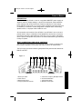
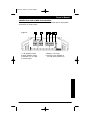
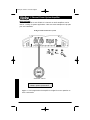
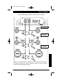
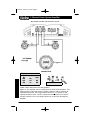
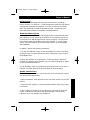
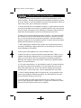
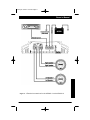
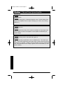
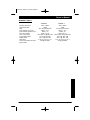
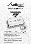
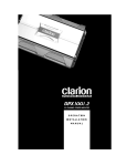
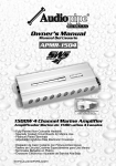
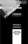
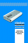
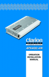
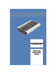
apx201.qxd 12/5/01 12:57 PM Page 1
2-CHANNEL POWER AMPLIFIER
O P E R A T IO N
INSTALLATION
MANUAL
apx201.qxd 12/5/01 12:57 PM Page 2
2 Channel Power System Amplifier
TABLE OF CONTENTS
Introduction . . . . . . . . . . . . . . . . . . . . . . . . . . . . . . . .
Description . . . . . . . . . . . . . . . . . . . . . . . . . . . . . . . . .
Input Connections and Audio Controls . . . . . . . . . . . .
Connections for Power and Speakers . . . . . . . . . . . . .
Applications . . . . . . . . . . . . . . . . . . . . . . . . . . . . . . . .
Installation . . . . . . . . . . . . . . . . . . . . . . . . . . . . . . . . .
Mounting Precautions . . . . . . . . . . . . . . . . . . . . . . . . .
Wiring Precautions . . . . . . . . . . . . . . . . . . . . . . . . . . .
Setting the Gain . . . . . . . . . . . . . . . . . . . . . . . . . . . . .
Setting the Crossover . . . . . . . . . . . . . . . . . . . . . . . . .
Setting the Bass Boost . . . . . . . . . . . . . . . . . . . . . . . .
Final System Checks . . . . . . . . . . . . . . . . . . . . . . . . .
Troubleshooting . . . . . . . . . . . . . . . . . . . . . . . . . . . . .
Product Specs . . . . . . . . . . . . . . . . . . . . . . . . . . . . . .
Warranty Information . . . . . . . . . . . . . . . . . . . . . . . . .
.
.
.
.
.
.
.
.
.
.
.
.
.
.
.
.2
.3
.3
.5
.6
.9
.9
.9
. 12
. 12
. 12
. 13
. 13
. 15
. 16
INTRODUCTION
The Clarion APX201.2 and APX401.2 are full-featured two-channel amplifiers
incorporating the following features:
• Full frequency response with low distortion and exceptional signal to noise
performance.
• Advanced circuitry design that features bridgeable and mixed mode operation
for use in various audio systems, including those with satellite speakers
and/or subwoofers.
• Variable high-pass/low-pass electronic crossover with a 12dB per octave
slope and full adjustable range (from 55Hz to 5.5kHz) to aid in any audio
system configuration.
• Variable bass boost circuit to reinforce low frequency signals that may be
lost due to subwoofer box design.
• Adjustable input level controls with ground loop isolation, allowing a wide
range of input signals.
• Remote turn-on with “soft start” muting to prevent turn on “thump”.
• Pulse-width modulated (PWM) MOSFET power supply with low AM RFI
and protection circuits for overheating and speaker shorts.
• 2-ohm load capability to drive a variety of speaker systems.
• Gold-plated input/output connectors and an external automotive type fuse
• Aluminum heat sink for efficient heat dissipation.
• Low profile, compact size for space limited installations.
ABOUT THE MANUAL AND WARRANTY
To start enjoying your new Clarion two-channel amplifier, please read the
instructions stated in this manual. Keep all instructions for future reference.
Save your original sales receipt as proof of purchase.
2
apx201.qxd 12/5/01 12:57 PM Page 3
Owner’s
Owner’sManual
Manual
DESCRIPTION
The APX201.2 and APX401.2 use an unregulated MOSFET power supply for
superior control of output wattage. A toroid-coil transformer yields maximum
power transfer with minimal heat loss. Extensive attention to circuit design
keeps AM RFI at low levels, so you won’t hear unwanted noise when the level
is cranked up. Protection circuits safeguard the amplifier when overheating,
speaker shorts, or improper load conditions occur.
All connections and controls of the APX201.2 and APX401.2 are on the end
panels and are easy to understand. Gold-plated RCA and barrier connectors
are used to ensure the best electrical connection for your system. Integrated
into the power and speaker end panel is an external automotive type fuse that
is easy to replace.
INPUT CONNECTIONS AND AUDIO CONTROLS
The front panel of the APX201.2 and APX401.2 both contain connections for
RCA Inputs or Speaker Level Inputs and Audio Controls as shown below.
The RCA input connections feature gold-plated RCA jacks and are labeled as
RIGHT and LEFT.
Figure 1-
1
1. RCA Input Jacks
2. Gain Control
3. Bass Boost Control
4. Freq (Hz) Selection Control
2
3
4
5
5.
6.
7.
8.
6
7
8
Crossover Frequency Multiplier Switch
X-Over Mode Switch
Input Select Switch
Speaker Level Inputs
3
apx201.qxd 12/5/01 12:57 PM Page 4
2 Channel Power System Amplifier
• Gain Control - This allows you to set the nominal operating level of the
amplifier. The amplifier’s range, 250mV to 2.5V for RCA inputs or 500mV to
5V for speaker level inputs, can accommodate input levels from virtually any
brand of source unit.
• Bass Boost Control- The amplifier also features a “high-Q” (i.e. narrow
frequency band) Bass Boost circuit. It acts much like an equalizer, with
adjustable gain (from 0 to +18dB) fixed at 45Hz. Use this feature to tune lowfrequency audio response to compensate for a less than ideal subwoofer
enclosure design. The added boost produces rich, full bass tones that are
normally difficult to reproduce in the car audio environment. NOTE: If Bass
Boost is undesired, set Bass Boost to 0dB.
High-pass/Low-pass Filter Controls
• Frequency (Hz) Selection Control - The crossover frequency is fully
adjustable between 55Hz to 5500Hz (via the Crossover Frequency Multiplier)
for a wide range of crossover points. Use this feature, along with your speaker manufacturer’s recommended crossover frequencies, to quickly design a
more advanced system (see Applications on page 5.) NOTE: If the X-Over
Mode Switch is set to OFF, varying the Freq (Hz) Control will produce no
effect.
• Crossover Frequency Multiplier Switch - When engaged, this switch
increases the crossover frequency by a factor of 10. Example: If the Freq (Hz)
dial is set for 240 Hz, pushing in the multiplier switch changes the setting to
2400 Hz.
• X-Over Mode Switch - This switch is equipped with a 12dB per octave
electronic filter for precise frequency attenuation with minimal phase distortion. The steep crossover slope keeps midrange tones out of the subwoofer
and thereby eliminates an unnatural “nasal” tone quality in the audio system.
The filter is activated by sliding the X-Over Mode Switch to either LP or HP.
• Input Mode Switch - This switch allows you to set the input mode. Stereo
input allows full left and right stereo operation. Right (bridged) input allows
single channel input for bridged operation. This is especially useful in high
powered systems when using one amplifier for each subwoofer/speaker.
L + R (sum mono) allows a stereo input to be summed into a mono output.
• Speaker Level Inputs - These provide connections for a high-level stereo
source. These connections are provided for installations when the source unit
does not have RCA outputs.
WARNING:When using the speaker (high-level) inputs, the Black wire must
be grounded at the radio. Failure to do this will result in noise and/or improper operation.
4
apx201.qxd 12/5/01 12:57 PM Page 5
Owner’s Manual
CONNECTIONS FOR POWER AND SPEAKERS
The rear panel of the APX201.2 and APX401.2 contains power and speaker
connections as shown below.
Figure 2-
1.
2.
3.
4.
1
Left Speaker Output
Right Speaker Output
Remote Turn-on Input
Ground Input
2
3
4
5
6
5. Battery +12V Input
6. 25 Amp Fuse (APX201.2)
40 Amp Fuse (APX401.2)
5
apx201.qxd 12/5/01 12:57 PM Page 6
2 Channel Power System Amplifier
APPLICATIONS
The Clarion APX201.2 and APX401.2 2-channel car audio amplifiers can be
used in a variety of system applications. Here are some examples to help plan
your own installation.
Bridged- Mono Subwoofer System
Subwoofer 4 Ohms
Set X-Over Mode to LP and adjust
FREQ to speaker specifications.
Figure 3 - In this application the amplifier is bridged for mono operation to
drive a subwoofer.
6
apx201.qxd 12/5/01 12:57 PM Page 7
Owner’s Manual
2-Channel Full-Range, Satellite, or Subwoofer Stereo System
Set X-Over Mode as shown
Set X-Over Mode as shown;
adjust FREQ to speaker
specifications.
Set X-Over Mode as shown;
adjust FREQ to speaker
specifications.
Figure 4 - In this application, the amplifier is used in stereo and drives two
full-range (or satellite or subwoofer) speakers. NOTE: A passive crossover
must be used with satellite speakers.
7
apx201.qxd 12/5/01 12:57 PM Page 8
2 Channel Power System Amplifier
Mixed-Mode Satellite and Subwoofer System
FREQ (hz)
80
100
125
150
200
L (mH)
8.0
6.4
5.1
4.2
3.2
C (uF)
497
398
Set X-Over Mode to OFF
NOTE: Chart values based on 4 ohm speakers.
Figure 5 - The amplifier can be configured for a mixed-mode operation. The
table provides component values to create a 6dB per octave crossover at
specified frequencies. Use components that have a + 5% tolerance and
capacitors rated at 100V. NOTE: Choose the same frequency for both LP
and HP crossovers. Do not overlap frequencies, as this may damage the
amplifier.
8
apx201.qxd 12/5/01 12:57 PM Page 9
Owner’s Manual
INSTALLATION
This section lists Mounting and Wiring Precautions prior to installing a
Clarion APX201.2 or APX401.2. These safeguards provide enough detail to
complete the installation successfully. If you do not have the necessary
skills, do not attempt to install the amplifier yourself. Instead, see your
authorized Clarion dealer for installation recommendations.
MOUNTING PRECAUTIONS
Although the Clarion APX201.2 and APX401.2 both incorporate heat sinks
and protection circuits, mounting the amplifier in a tight space without any
air movement can still damage internal circuitry over time. Choose a site
that provides adequate ventilation around the amplifier. For easy system
set-up, mount the amplifier so the front panel controls can be accessible
after installation.
In addition, observe the following precautions:
1. For the most efficient cooling, mount the amplifier so cool air runs along
the length of the fins rather than across them. Remember, any moving air
will dissipate heat.
2. Mount the amplifier on a rigid surface. Avoid mounting to subwoofer
enclosures or areas prone to vibration. Do not install the amplifier on plastic
or other combustible materials.
3. Prior to drilling, make sure proposed mounting holes will not cut into the
fuel tank, fuel lines, brake lines (under chassis) or electrical wiring.
WIRING PRECAUTIONS
Read all wiring precautions. If you are not sure of the connections, contact
your authorized Clarion dealer.
1. Before installation, make sure the source unit Power switch is in the OFF
position.
2. Disconnect the negative (-) lead of the battery before making any power
connections.
3. When making connections, be sure that each connection is clean and
secure. Insulate final connections with electrical tape or shrink tubing.
Failure to do so may damage your equipment.
9
apx201.qxd 12/5/01 12:57 PM Page 10
2 Channel Power System Amplifier
4. A secure, clean ground connection is critical to the performance of your
Clarion amplifier. Use the shortest ground wire possible and securely connect
to the car chassis to minimize resistance and avoid noise problems. Besure to
clean off any paint, prior to making this connection.
5. Add an external fuse on the amplifier’s positive (+) power lead and connect
it as close as possible to the vehicle’s (+) battery terminal. Use a fuse rated to
the total current consumption of the amplifier(s). Adding an external fuse will
protect the electrical system from short circuits that can cause a fire.
6. Refer to Figure 6 when making electrical connections. Connect the amplifier’s positive (+) lead via a fuse directly to the positive (+) terminal on the battery. Do not connect this wire to the car’s fuse panel. Use red-insulated 10gauge (or larger) wire for the amplifier’s positive (+) power lead and the samegauge black-insulated wire for the ground.
7. When replacing the amplifier’s fuse, always use one having the same current rating. Substituting a higher-rated fuse or a slow-blow type can result in
serious damage to the amplifier.
8. Never ground the speakers to the vehicle chassis or body.
9. Make sure that your vehicle’s electrical system (alternator, battery, etc.) is
capable of handling the additional load. If you are planning a multi-amplifier
system, you may need to add a second battery and possibly upgrade the
alternator with a higher-output rated model. Consult your authorized Clarion
dealer for recommendations.
10. To avoid noise problems, run the amplifier’s positive (+) power lead along
one side of the vehicle from the battery. Run the remote turn-on wire and
RCA audio cables down the center, and route the speaker wires along the
remaining side. If wires must cross, run them perpendicular to each other.
11. When creating passage holes for the power wire, use grommets to eliminate any sharp edges created during drilling. This will protect the wire from
being nicked and causing a short circuit.
12. Excess cable can cause signal loss and act as an “antenna” for noise.
Use only high-quality RCA cables that are no longer than necessary to make
a direct connection with the source unit or equalizer.
10
apx201.qxd 12/5/01 12:57 PM Page 11
Owner’s Manual
Figure 6. - Electrical connections for the APX201.2 or the APX401.2
11
apx201.qxd 12/5/01 12:57 PM Page 12
2 Channel Power System Amplifier
SETTING THE GAIN
After completing the installation, follow these steps to set the Gain Control
and then perform the Final System Checks.
1. Turn the Gain Control all the way counter-clockwise.
2. Turn the vehicle’s Ignition Switch to the ON position. Then turn the
ON/OFF Switch on the source units to the ON position. Set all Tone or
Equalization Controls to “flat” positions and turn Loudness off.
3. Play a CD or Tape and set the Volume Control at 75% of full level.
NOTE: If the system uses an equalizer, set its frequency controls to “flat”
positions.
4. Slowly increase the Gain Control. Stop when you hear a slight distortion of
audio.
SETTING THE CROSSOVER
The Clarion APX201.2 and APX401.2 feature a fully adjustable crossover.
To set the crossover, follow these steps.
1. Using the X-Over Mode Switch, select the desired mode: LP for Low Pass,
HP for High Pass or OFF for Full Range.
2. Using the Freq (Hz) Control, select the desired frequency. If the desired
frequency exceeds the range of the Freq (Hz) Control, press the Crossover
Frequency Multiplier Switch to increase the value by a multiplier of 10.
• For example, 55Hz x 10 = 550Hz or 550Hz x 10 = 5.5kHz.
SETTING THE BASS BOOST
1. Initially set the Bass Boost control to its full left position (i.e. 0dB).
2. Listen to a variety of music styles (e.g. Rock, Rap, etc.) and slowly
increase the Bass Boost control until a noticeable increase in low bass
response is perceived.
3. Slowly adjust the Bass Boost control (up or down) to realize the best bass
response.
CAUTION: If you hear a “pop” (due to speaker over-excursion), lower the
Bass Boost to prevent speaker damage. If the system sounds muddy and distorted (due to amplifier clipping), lower Bass Boost to avoid shutdown from
overheating.
12
apx201.qxd 12/5/01 12:57 PM Page 13
Owner’s Manual
FINAL SYSTEM CHECKS
1. Start the engine and turn on the source unit. After a two-second delay, slowly increase the Volume Control and listen to the audio. If you hear any noise,
static, distortion or no sound at all, check the connections, and also refer to
Troubleshooting. Depending on your system design, the levels may become
quite loud even at low Volume Control settings. Until you get an “audio feel” of
the system’s power, use care when adjusting controls.
2. Turn the Balance Controls to their extreme positions and listen to the results.
Audio imaging should match control settings (audio from the left speaker when
balance is left).
3. Increase the volume and verify that the amplifier reproduces audio (at full frequencies) without distortion. If you hear distortion, check the connections and
verify that the Gain Control is set correctly. Another possibility is damaged
speakers or under-powered speakers. Once again refer to Troubleshooting for
additional help.
TROUBLESHOOTING
Problem
No Audio.
Solution
Low or no remote turn-on voltage. Check remote connections at
amplifier and source unit.
Blown amplifier fuse. Replace with new fast-blow fuse (same rating).
Power wires not connected. Check battery and ground wiring at
amplifier; also check battery connections.
Speaker leads shorted. Check speaker continuity to ground, it should
not show a common ground.
Speakers not connected or are blown. Check speaker connections at
amplifier, measure coil impedance.
Problem
Audio cycles on and off.
Solution
Thermal protection circuits are shutting amplifier off. Check location for
adequate ventilation; consult an authorized Clarion Audio Dealer.
13
apx201.qxd 12/5/01 12:57 PM Page 14
2 Channel Power System Amplifier
Problem
Distorted audio.
Solution
Gain is not set properly, or damaged speaker cones. Review Setting Gain;
inspect each speaker cone for signs of damage (i.e. frozen cone, burning
smell, etc.)
Problem
Audio lacks punch.
Solution
Speakers wired incorrectly, which causes cancellation of bass frequencies.
Check polarity of wires from amplifier to each speaker as defined by the
system design.
Problem
Whining or ticking noise in the audio with engine on.
Solution
Amplifier is picking up alternator noise or radiated noise. Turn down input
gain; move audio cables away from power wires. Check power and ground
connections on amplifier; install an in-line noise filter on source unit’s power
wire; check alternator and/or voltage regulator; test for weak battery or add
water to battery.
14
apx201.qxd 12/5/01 12:57 PM Page 15
Owner’s Manual
PRODUCT SPECS
APX201.2
Frequency Response
Signal Noise Ratio
THD
Input Sensitivity Low Level
Input Sensitivity Speaker Level
Max. Power Output
Cont. Power Output
2-Ohm Stereo Output
Bridged Power
Dimensions
Current Consumption at output
@ max power
20Hz ~ 20kHz
>100db
.05% all channels driven
250mV ~ 2.5 V
500mV - 5V
220w (110 x 2)
100w (50w x 2) @.08% THD
110 x 2 @ .05% THD
220 x 1 @ .05% THD
2 1/8” H x 8 1/4” W x 9” L
28A @ 235 Watts
APX401.2
20Hz ~ 20kHz
>98db
.05% all channels driven
250mV ~ 2.5 V
500mV - 5V
380w (190 x 2)
200w (100w x 2) @ .08% THD
190 x 2 @ .05% THD
280 x 1 @ .05% THD
2 1/8” H x 8 1/4” W x 12” L
43A @ 382 Watts
15
apx201.qxd 12/5/01 12:57 PM Page 16
WARRANTY INFORMATION
This product is warranted against all defects in material workmanship for a period of one year from the date of
original purchase. Clarion ProAudio products except for speakers are covered by a two year warranty when
installed by an authorized Clarion dealer. The conditions of this warranty and the extent of responsibility of
Clarion Corporation under this warranty are as follows:
1. PROOF OF DATE OF PURCHASE WILL BE REQUIRED FOR WARRANTY SERVICE OF THIS PRODUCT.
IN CASE OF 2 YEAR WARRANTY FOR CLARION PROAUDIO PRODUCT, PROOF OF INSTALLATION BY
AUTHORIZED DEALER IS REQUIRED. INFORMATION ABOUT CLARION AUTHORIZED WARRANTY
SERVICE CENTERS MAY BE OBTAINED BY CONTACTING OR WRITING CLARION CORPORATION AT
THE ADDRESS LISTED BELOW.
2. This warranty will become void if service performed by anyone other than an approved Clarion Warranty
Service Center results in damage to product.
3. This warranty does not apply to any product which has been subject to misuse, neglect or accident, or which
has had the serial number altered, defaced or removed, or which has been connected, installed, adjusted or
repaired, other than in accordance with the instructions furnished by Clarion Corporation.
4. This warranty does not cover car static or other electrical interferences, tape head cleaning or adjustments, or
labor costs for the removal or reinstallation of the unit for repair.
5. The sole responsibility of Clarion Corporation under this Warranty shall be limited to the repair or replacement
thereof, at the sole discretion of Clarion Corporation.
6. If it becomes necessary to send the product or any defective part to Clarion Corporation or an authorized
warranty service station, the product must be shipped in its original carton or equivalent carton, fully insured,
with shipping charges prepaid. Clarion Corporation will not assume any responsibility for any loss or damage
incurred in shipping.
7. ALL IMPLIED WARRANTIES EXCEPT TO THE EXTENT PROHIBITED BY APPLICABLE LAW SHALL HAVE
NO GREATER DURATION THAN THE WARRANTY PERIOD SET FORTH ABOVE. UNDER NO
CIRCUMSTANCES SHALL CLARION CORPORATION BE LIABLE FOR ANY LOSS OR DAMAGE, DIRECT
OR CONSEQUENTIAL, ARISING OUT OF THE USE OR INABILITY TO USE THE PRODUCT. BECAUSE
SOME STATES DO NOT ALLOW LIMITATIONS ON HOW LONG AN IMPLIED WARRANTY LASTS OR
EXCLUSIONS OR LIMITATIONS OF INCIDENTAL OR CONSEQUENTIAL DAMAGES, THE ABOVE
LIMITATIONS OR EXCLUSIONS MAY NOT APPLY TO YOU.
8. THIS WARRANTY GIVES YOU SPECIFIC LEGAL RIGHTS, AND YOU MAY ALSO HAVE OTHER RIGHTS
WHICH VARY FROM STATE TO STATE.
9. For instructions on how to obtain warranty service, please call 1-800-GO-CLARION or visit our web site at
www.clarion.com for a listing of Authorized Warranty Service Centers in your area, or contact the Clarion
Customer Service Manager at the address listed below:
Clarion Corporation of America
661 W. Redondo Beach Blvd.
Gardena, CA 90247-4201 U.S.A.
16
APX201.2.401.2 Rev. 1(11/01)