1
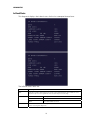
IN STALLAT ION MANUA L
DCH100
Installation Manual
IMPORTANT SAFETY INSTRUCTIONS
•
Read these instructions.
•
Keep these instructions.
•
Heed all warnings.
•
Follow all instructions.
•
Do not use this apparatus near water.
•
The apparatus shall not be exposed to dripping or splashing and no objects filled with liquids,
such as vases, shall be placed on the apparatus.
•
Clean only with dry cloth.
•
Do not block any ventilation openings. Install in accordance with the manufacturers
instructions.
•
Do not install near any heat sources such as radiators, heat registers, stoves, or other
apparatus (including amplifiers) that produce heat.
•
Do not defeat the safety purpose of the polarized or grounding-type plug. A polarized plug has
two blades with one wider than the other. A grounding type plug has two blades and a third
grounding prong. The wide blade or the third prong is provided for your safety. If the provided
plug does not fit into your outlet, consult an electrician for replacement of the obsolete outlet.
•
Protect the power cord from being walked on or pinched particularly at plugs, convenience
receptacles, and the point where they exit from the apparatus.
•
Only use attachments/accessories specified by the manufacturer.
•
Unplug this apparatus during lightning storms or when unused for long periods of time.
•
Refer all servicing to qualified service personnel. Servicing is required when the apparatus has
been damaged in any way, such as the power-supply cord or plug is damaged, liquid has been
spilled or objects have fallen into the apparatus, the apparatus has been exposed to rain or
moisture, does not operate normally, or has been dropped.
IMPORTANT SAFETY CONSIDERATIONS
Be sure to follow these requirements during transportation and installation.
The plug is the mains disconnect device. It shall remain readily accessible and operable.
DURING TRANSPORTATION TO THE SUBSCRIBER HOME
Transport the cable terminal in its shipping box or an equally padded container.
Do not expose the terminal to rain or moisture.
i
DURING INSTALLATION
•
Do not place the cable terminal in an enclosed area where the cooling vents are blocked or
impede the flow of air through the ventilation openings.
•
Install the terminal so that its position does not interfere with its proper ventilation. For
example, do not place the terminal on a bed, sofa, rug, or similar surface that could block the
ventilation openings.
•
Install the terminal away from heat sources such as radiators, heat registers and stoves.
Installation of the terminal near consumer electronics devices, such as stereo
receiver/amplifiers and televisions, is permitted as long as the air surrounding the terminal
does not exceed 40º C (104º F).
•
Place the terminal on a flat surface not prone to vibration or impact.
•
Do not install the terminal in an area where condensation occurs.
•
To prevent the temporary loss of guide data and cause a temporarily non-responding terminal,
do not plug the AC power cord into a switched power outlet.
FCC COMPLIANCE
Note: This equipment has been tested and found to comply with the limits for a Class B digital device,
pursuant to part 15 of the FCC Rules. These limits are designed to provide reasonable protection
against harmful interference in a residential installation. This equipment generates uses and can radiate
radio frequency energy and, if not installed and used in accordance with the instructions, may cause
harmful interference to radio communications. However, there is no guarantee that interference will
not occur in a particular installation. If this equipment does cause harmful interference to radio or
television reception, which can be determined by turning the equipment off and on, the user is
encouraged to try to correct the interference by one or more of the following measures:
•
Reorient or relocate the receiving antenna.
•
Increase the separation between the equipment and receiver.
•
Connect the equipment into an outlet on a circuit different from that to which the receiver is
connected.
•
Consult the dealer or an experienced radio/TV technician for help.
Caution: Changes or modifications not expressly approved by Motorola for compliance could void the
user’s authority to operate the equipment.
This device complies with part 15 of the FCC Rules. Operation is subject to the following two
conditions: (1) This device may not cause harmful interference, and (2) this device must accept any
interference received, including interference that may cause undesired operation.
ii
FCC DECLARATION OF CONFORMITY
Motorola Inc., Connected Home Solutions, 101 Tournament Drive, Horsham, PA 19044, 1-215-3231000, declares that the DCH100 receiver complies with 47 CFR Parts 2 and 15 of the FCC rules as a
Class B digital device.
Canada Industry Canada (IC)
This Class B digital device complies with Canadian ICES-003.
Cet appareil numérique de la classe B est conforme à la norme NMB-003 du Canada.
CARING FOR THE ENVIRONMENT BY RECYCLING
When you see this symbol on a Motorola product, do not dispose of the product
with residential or commercial waste.
Recycling your Motorola Equipment
Please do not dispose of this product with your residential or commercial waste.
Some countries or regions, such as the European Union, have set up systems to
collect and recycle electrical and electronic waste items. Contact your local
authorities for information about practices established for your region. If collection
systems are not available, call Motorola Customer Service for assistance.
© 2007 Motorola, Inc. All rights reserved. MOTOROLA and the Stylized M logo are registered in the US
Patent and Trademark Office. CableCARD and M-Card are trademarks or registered trademarks of
Cable Television Laboratories, Inc. Manufactured under license from Dolby Laboratories. “Dolby” and
the double-D symbol are trademarks of Dolby Laboratories. Macrovison is a registered trademark of
Macrovision Corporation. All other product or service names are the property of their respective
owners.
No part of this publication may be reproduced in any form or by any means or used to make any
derivative work (such as translation, transformation, or adaptation) without written permission from
Motorola, Inc.
Motorola reserves the right to revise this publication and to make changes in content from time to time
without obligation on the part of Motorola to provide notification of such revision or change. Motorola
provides this guide without warranty of any kind, implied or expressed, including, but not limited to, the
implied warranties of merchantability and fitness for a particular purpose. Motorola may make
improvements or changes in the product(s) described in this manual at any time.
iii
CONTENTS
1 Introduction ........................................................................................................................................................... 1
Features............................................................................................................................................................. 2
Tuner ........................................................................................................................................................... 2
Standard Audio/Video Features ............................................................................................................. 2
Standard Data Features........................................................................................................................... 2
Standard Miscellaneous Features......................................................................................................... 2
If You Need Help............................................................................................................................................... 3
Calling for Repairs............................................................................................................................................ 3
2 Overview ................................................................................................................................................................ 5
Front Panel ........................................................................................................................................................ 5
Rear Panel ......................................................................................................................................................... 6
M-Card™ ........................................................................................................................................................... 6
3 Installation ............................................................................................................................................................. 7
Before You Begin.............................................................................................................................................. 7
Video Connection Options ....................................................................................................................... 7
Audio Connection Options....................................................................................................................... 8
Installation Overview....................................................................................................................................... 8
Cabling to a Standard-Definition TV and an A/V Receiver ........................................................................ 9
Cabling to a Standard-Definition TV and Audio Receiver........................................................................ 10
Data Device Connections ............................................................................................................................. 11
Operational Check for the Remote Control ................................................................................................ 12
Graphics Overlaying the Video .................................................................................................................... 12
4 Diagnostics.......................................................................................................................................................... 13
Using the Diagnostics.................................................................................................................................... 13
General Status ................................................................................................................................................ 14
Out-Of-Band (OOB) Status............................................................................................................................ 16
Agile OOB Tuner Hunting .............................................................................................................................. 17
Summary of Operator Selection of the OOB Frequency
(OSD Frequency Override in Hunted Mode) ....................................................................................... 17
In-Band Status................................................................................................................................................ 19
Audio/Video Status ........................................................................................................................................ 21
Unit Address.................................................................................................................................................... 23
Separable Security ........................................................................................................................................ 25
Firmware Version ........................................................................................................................................... 26
Current Channel Status ................................................................................................................................. 27
Renewable Security....................................................................................................................................... 29
Upstream Modem........................................................................................................................................... 30
v
CONTENTS
App Code Modules.........................................................................................................................................31
Memory Configuration...................................................................................................................................33
Interactive Status ...........................................................................................................................................34
MAC Frequency Table....................................................................................................................................36
Control Channels ............................................................................................................................................36
Message Types...............................................................................................................................................37
In-band Program Association Table (PAT)..................................................................................................37
In-band Program Map Table (PMT).............................................................................................................38
Task Status ......................................................................................................................................................38
USB Diagnostic...............................................................................................................................................39
In-band Multicast Address Filter .................................................................................................................39
Connected Home Status................................................................................................................................40
Keyboard / LED................................................................................................................................................43
5 Troubleshooting...................................................................................................................................................45
Figures
Figure 1-1 Front and rear views ....................................................................................................................... 1
Figure 3-1 Cabling to a Standard-Definition stereo TV ................................................................................ 9
Figure 3-2 Cabling an audio receiver.............................................................................................................. 10
Figure 3-3 Sample data devices you can connect to the DCH100.............................................................. 11
Tables
Table 3-1 Operational check procedures....................................................................................................... 12
vi
1 INTRODUCTION
This manual provides instructions for cable operator personnel to install the Motorola
DCH100 cable receiver. This unit includes a high-end processor, expanded memory,
and enhanced graphics to support digital, on-demand, and interactive services.
The DCH100 provides advanced capabilities, including:
•
Authorization and purchase of on-demand programming
•
Surround-sound audio through a variety of analog and digital interconnection
options
•
Adaptability to various software platforms
As with all Motorola digital cable receivers, the hardware features are enabled by
core operating and third party application software.
Figure 1-1 Front and rear views
1
1 INTRODUCTION
Features
Tuner
•
Digital MPEG-2 main profile main level video processor
•
Provides an out-of-band (OOB) control channel
Standard Audio/Video Features
•
ITU standard 64/256 QAM/FEC/enhanced adaptive equalizer
•
DES based encryption/DCII (via inserted CableCARD™) access control
•
Out-of-band data receiver (70-130 MHz) 2.048 Mbps
•
Digital video scaling (picture in graphics)
•
32-bit 2D graphics support in hardware
•
Macrovision® copy protection
•
Standard-Definition video output through:
o
S-Video
o
Baseband
o
RF
•
Audio output through:
•
Digital audio (S/PDIF) ATSC standard Dolby Digital® AC-3 electrical or optical
•
Baseband L/R
Standard Data Features
•
32 MB flash memory
•
128 MB SDRAM
•
On-board real-time RF return
Standard Miscellaneous Features
•
Messaging capabilities
•
Digital diagnostics
2
1 INTRODUCTION
If You Need Help
If you need assistance while working with the DCH100, contact the Motorola
Technical Response Center (TRC):
Inside the U.S.: 1-888-944-HELP (1-888-944-4357)
Outside the U.S.: 1-215-323-0044
Motorola Online: http://businessonline.motorola.com/
The TRC is on call 24 hours a day, 7 days a week. In addition, Motorola Online offers
a searchable solutions database, technical documentation, and low-priority issue
creation and tracking.
Calling for Repairs
If a Motorola DCH100 set-top requires repair service, please call one of the following
Motorola Authorized Service Centers:
Company
From USA or Canada
Outside USA or Canada
World Wide Digital
1-800-227-0450
1-956-541-0600
Teleplan
1-800-352-5274
1-302-322-6088
To ensure efficient service, request a Return for Service Authorization (RSA) number.
Be sure to display the RSA number prominently on all equipment boxes.
The Service Center will provide the shipping address of the location performing your
repairs.
To ship your equipment for repair:
•
Pack the unit securely, if possible in its original factory shipping carton.
•
Print or display the RSA number so it is easily visible on all equipment boxes.
•
Enclose a note describing the exact problem. Complete and enclose the
checklist provided with the unit.
•
Ship the unit PREPAID to the address provided by the Service Center.
3
2 OVERVIEW
Front Panel
1
Power Indicator — Lit when the unit is powered ON, unlit when unit is OFF
2
Message Indicator* — Lit when a new message is waiting to be read, unlit otherwise
*Availability of certain features is dependent upon application support.
5
2 OVERVIEW
Rear Panel
1
Cable In — Connects to cable signal from your service provider
2
RF Out — Ch 3/4 modulated audio/video (SDTV) to TV or VCR
3
Digital Audio Optical (S/PDIF) — Provides Dolby® Digital 5.1 audio or PCM output
4
S-Video — Connects to S-Video (SDTV) input of TV or VCR
5
Digital Audio Coaxial (S/PDIF) — Provides Dolby® Digital 5.1 audio or PCM output
6, 7
Video/Audio Out — Composite Video (SDTV) /Audio outputs
8
USB* 1.1 — High-Speed peripheral device connection
9
Serial — Service only
10
External IR connector
11
Power cord supply connector
12
M-Card — Inserted M-Card
*Availability of certain features is dependent upon application support.
M-Card™
The M-Card is required to view cable television programs, previously recorded
programs on the DVR, or interactive on-demand programs. The M-Card should not
be removed.
6
3 INSTALLATION
Before You Begin
Before you move or change components on the subscriber entertainment system:
•
Review the installation instructions.
•
Determine if you are connecting to a standard TV or a composite (baseband)
monitor.
•
Verify that you have the necessary cables and other required items.
Video Connection Options
Use the following guidelines to determine the best video connection for the
subscriber home entertainment system. To determine the available video inputs on
the TV, check the manual supplied with the TV or the TV itself.
The DCH100 offers the following video outputs:
S-Video
SDTV only
If your TV has an S-Video input, use S-Video. S-Video is the highest
quality standard-definition video output on the DCH100.
Video
(composite)
SDTV only
If your TV does not have an S-Video input, use the composite video
(video) output.
RF
SDTV only
If your TV only has a coaxial RF input, connect it to the DCH100 RF out
connector.
7
3 INSTALLATION
Audio Connection Options
Connect the stereo audio cable to the AUDIO L and R connectors on the DCH100
and the audio left and right connectors on the TV. If the equipment supports it, use
the optical SPDIF or coaxial digital SPDIF output instead of the AUDIO L and R
outputs. In most cases, these outputs offer better audio quality, including support for
5.1 Surround Sound.
When connecting to a home theater receiver, depending on its inputs, you can use
the following DCH100 audio outputs:
Digital audio optical
(S/PDIF) or digital audio
coaxial (S/PDIF)
If the receiver supports it, use the digital audio optical (S/PDIF) or digital
audio coaxial (S/PDIF) audio output to deliver Dolby AC-3 audio to a
Dolby Digital home theater receiver.
Baseband Audio R and L
If the audio receiver does not support Dolby Digital, use the baseband
AUDIO L and R outputs to connect to the audio receiver.
The cabling diagrams show sample audio/video (A/V) connections to an audio
receiver, where the receiver functions as an A/V router. When connecting to an audio
receiver, reference its installation instructions for directions on connecting to
baseband and digital (S/PDIF) ports.
The VCR and TV receive their A/V signals from the currently selected input device on
the audio receiver. This is important when the subscriber has another A/V device
such as a DVD player, a secondary VCR, a CD player, or other electronic component.
We recommend connecting the TV to the monitor output so on-screen menus for
the receiver can be displayed. (In many cases, the receivers themselves have
interactive on-screen menus).
Installation Overview
1. Connect the S-Video connector using an S-video cable or connect the composite
video connector using a composite (RCA phono) cable. If the TV only has a
coaxial RF input, connect it to the DCH100 RF OUT connector.
2. Determine if you are connecting the audio to a home theater receiver or directly
to the TV:
•
If the receiver or TV has an S/PDIF input, use the digital audio optical (S/PDIF)
or coaxial (S/PDIF) outputs.
•
Otherwise, use the baseband left and right audio out outputs.
3. Locate the cabling diagram(s) that best match the subscriber configuration.
4. Connect the audio and video cables in a manner matching that diagram.
5. Determine if you are connecting to a data device (see “Data Device
Connections” in this section). For installation details, refer to instructions
included with the data device.
6. Connect the cable terminal to the coaxial cable wall outlet.
7. Perform the operational check for the remote control.
8
3 INSTALLATION
Cabling to a Standard-Definition TV and an A/V Receiver
Figure 3-1 Cabling to a Standard-Definition stereo TV
DIGITAL
AUDIO
L
RF OUT
AUDIO
EXT IR
R
RF IN
S-VIDEO
VIDEO
USB
SERIAL
POWER
M-CARD™ DEVICE ONLY
Standard-Definition
stereoTV
Stereo VCR
A/V Receiver
Because some entertainment equipment cannot simultaneously support baseband
composite video and S-Video, never simultaneously connect both video inputs.
9
3 INSTALLATION
Cabling to a Standard-Definition TV and Audio Receiver
To connect to an audio receiver, such as a home mini system, follow a daisy-chain
convention. The A/V configuration illustrated enables digital stereo recording,
including Dolby Surround sound. Use only one set of composite input connectors on
the stereo:
Figure 3-2 Cabling an audio receiver
L/R audio
connection
Video
connection
S-Video
connection
Optical
connection
DCH100
DIGITAL
AUDIO
L
RF OUT
AUDIO
EXT IR
R
RF IN
S-VIDEO
VIDEO
USB
POWER
SERIAL
M-CARD™ DEVICE ONLY
Cable in
INPUT
OUTPUT
CABLE/
ANTENNA IN S-VIDEO VIDEO
AUDIO
AUDIO
ToTV
R
L
AUDIO IN
AUDIO OUT
10
R
L
R
L
VIDEO S-VIDEO
3 INSTALLATION
Data Device Connections
The DCH100 provides optional high-speed data services through its USB 1.1 port.
The functionality requires and depends on installed application software. The USB
1.1 port can be used to daisy-chain USB devices such as printers and storage
devices, or to interface with keyboards, joysticks, and other USB PC peripherals.
Figure 3-3 Sample data devices you can connect to the DCH100
11
3 INSTALLATION
Operational Check for the Remote Control
The operational check tests communication with the remote control:
Table 3-1 Operational check procedures
Feature
Testing Procedure
Power on
Press power on the remote control to turn on the DCH100.
Tune to the output channel (3 or 4).
Channel selection
Scan through the channels using the channel + or - keys.
Tune to several channels by entering the channel number using the
numeric keys.
Volume control
Press volume + or - on the remote control to increase the volume to its
upper limit, lowest level, and to a comfortable level.
Press mute to turn the sound off. Press mute again to restore the
sound.
If the DCH100 does not operate properly, refer to the Troubleshooting section.
Graphics Overlaying the Video
The DCH100 can generate graphics that overlay the video programming or fill the
entire television screen. Common examples include on-screen menus (such as the
On-Screen Diagnostics) and EPG. The DCH100 overlays these graphics whenever
you open a menu or scroll through a program grid.
On-screen graphics are available for all DCH100 video outputs.
12
4 DIAGNOSTICS
Diagnostics are displayed on the on-screen display (OSD). They confirm proper
installation, including:
•
Checking error states and signal integrity
•
Identifying the cable terminal on the network
•
Verify communications with the headend
For the diagnostics described in this section:
•
All indicators are in decimal notation, unless otherwise noted.
•
All signal-level and quality indicators use a 0 to 100% scale, unless otherwise
noted.
•
All sample displays are illustrative; actual data may differ from the examples.
•
All screens self-refresh at a minimum rate of once every five seconds.
You can use the diagnostics when running the Base Platform software.
Using the Diagnostics
To operate the set-top, use the Motorola universal remote control. To access and
navigate the diagnostic mode:
1. Ensure that the DCH100 is installed with the Base Platform software and that it
is connected to an AC outlet.
2. Press POWER on the remote control to turn on the set-top.
3. Wait five seconds and then press POWER again to turn off the set-top.
To enable diagnostic mode, press SELECT/OK on the remote control within two
seconds after powering off. The DIAGNOSTICS main menu is displayed on the OSD:
You can use the following keys to navigate the diagnostics menus:
•
Press channel ▲, channel ▼, cursor ▲, or cursor ▼ to select d01 through d22.
13
4 DIAGNOSTICS
•
Press cursor ◄, cursor ►, SELECT or ENTER to execute the selected diagnostic.
•
To exit the diagnostic mode, press POWER on the remote control. The set-top
exits the diagnostic mode and powers off.
General Status
This diagnostic displays the error code and description, purchase count, and other
information:
The General Status fields are:
Field
Description
Error
Error codes display on the OSD when an error occurs. If multiple errors occur, the last
recorded error is displayed:
Error Code
Description
Cause
Remedy
E 00
NO ERROR
Indicates normal condition
after initialization
None
E 01
NOT
CONNECTED
The set-top did not receive a
connect message
Restore out-of-band signal
E 02
PWR CYCLE
Init Error
The set-top needs a power cycle
to recover
E 03
DRAM
DRAM error
Not used
E 04
DPSRAM
DP-SRAM error
Not used
E 07
ROM
ROM verification failure
Power cycle the set-top; if
repetitive, return for repair
E 08
RAM
Faulty RAM, ROM, EEPROM,
or POST failure (this is a
hardware failure)
Return the set-top for repair
E 09
BATTERY
Dead battery or memory has
not been initialized; occurs if
battery fails to keep the RAM
alive during power-down;
Return the set-top for repair;
requires factory initialization
message
14
Send a connect message
4 DIAGNOSTICS
Field
Description
disconnects the set-top
E 10
SERIALNO
Invalid serial number
Not used
E 11
INVALID UNIT
ADDRESS
Invalid unit address
Return the set-top for repair;
requires a unit creation message
E 12
POST ERROR
POST failed
Not used
E 13
BOOT
Sys_boot initialization failure
Power cycle the set-top; if
repetitive, return for repair
E 14
STARTUP
System startup failure
Power cycle the set-top; if
repetitive, return for repair
E 15
TSI INVALID
TSI Structure is corrupted
Power cycle the set-top; if
repetitive, return for repair
E 16
FLASH BAD
NUMBER
Bad flash number specified
for Initiate Flash Platform
Error logged, ignore
E 17
BAD PLATVAL
Bad platform validation step
number
Error logged, ignore
Purchases
Indicates the number of unreported subscriber event purchases stored on the
product.
Platform ID
A unique 16-bit hexadecimal number that identifies the platform image (also called the
ROM ID).
Mapped
Platform ID
A unique 16-bit hexadecimal number that identifies the platform image (also called the
ROM ID), used in place of the Platform ID for certain third party applications.
Family ID
The manufacturer and product family, in hexadecimal
Model ID
The model, in hexadecimal
Remod
Channel
The interface to the subscriber TV; channel 3 or 4 in the USA
Time Zone
The time zone offset (in minutes) relative to GMT
DST Entry
Time
The daylight savings entry time.
DST Exit
Time
The daylight savings exit time.
Current GPS
Time
The current time.
15
4 DIAGNOSTICS
Out-Of-Band (OOB) Status
This diagnostic indicates the status of the out-of-band control channel.
The Out-Of-Band Status fields are:
Field
Description
Data
Indicates whether data is being carried by the OOB (the indicators cover all packet
processors regardless of which stream they are monitoring and are cleared when you enter
the diagnostic).
SNR
OSD
Description
“*”
OOB data detected within last 5 seconds
blank
OOB data not detected within last 5 seconds
When carrier lock has been established, displays an estimate of the carrier signal-to-noise
ratio in dB, with an explanation:
GOOD — Good value
FAIR — Marginal signal level, check the signal
POOR — Unusable signal
INVALID — Invalid SNR value
EMM
Data
Carrier
Lock
Indicates whether the set-top is receiving a message on the EMM Stream
OSD
Description
“*”
EMM data detected within last 5 seconds
blank
EMM data not detected within last 5 seconds
The CARRIER LOCK is reset to “1” after an initialization from the headend or a power cycle.
Each time the set-top detects a drop in OOB connectivity, the counter increments.
OSD
Description
YES
Carrier locked
NO
Carrier unlocked
16
4 DIAGNOSTICS
Field
Description
Hunt
Mode
The state of OOB stream acquisition.
OSD
Description
None
The set-top is locked to an OOB carrier
RR (Round
Robin)
The set-top is searching OOB frequencies trying to find an EMM Provider of
0 or 1.
EMM
The set-top received a Provider ID change and is searching OOB frequencies
for a new ID.
FIX
The set-top has been commanded to attempt to lock onto a frequency
SRCH
The set-top at some point had a valid Provider ID on the OOB frequency and
is attempting to re-acquire it.
Cur Freq
The current out-of-band frequency
LKC
The last known carrier (OOB frequency that had correct Provider ID)
EMM
Provider
ID
The ID of the provider of the Entitlement Management Message (EMM)
Agile OOB Tuner Hunting
Manual control for selecting an OOB frequency can be made while in the OOB
Status diagnostics screen by pressing the Menu button. To exit this mode, press the
Menu button a second time, or press the Power button.
If the set-top is in the process of hunting for an OOB frequency, control of frequency
selection is suspended, i.e. pressing Menu button on OOB status screen to display
MANUAL FREQ is not available when the set-top is hunting.
Summary of Operator Selection of the OOB Frequency (OSD Frequency Override in Hunted Mode)
The manual override frequency capability is only displayed if the box is not currently
hunting and the operator presses the MENU key while OOB OSD diagnostics are
displayed. The MANUAL FREQ displays the LKC and allows the operator to select
(vial scroll up/down) a specific frequency to check if a valid OOB is on that specific
frequency. The MANUAL FREQ parameter is the OOB frequency selected in the
frequency selection mode and displayed in MHz, with the specific values of: 75.25,
104.20, 72.75, 92.25, 98.25, 107.25, 107.40, 110.25, 116.25, and 103.75.
1. When in the OOB Receiver Status Diagnostic press the MENU button to enter
the frequency selection mode. The OSD displays a new “MANUAL FREQ” line
at the bottom of the screen, which indicates the last known carrier frequency. At
this point, if desired, the operator can exit the frequency change mode by
pressing the MENU key a second time.
2. The operator can use the UP/DOWN channel or cursor keys to scroll through all
10 frequencies until the desired new OOB frequency is found. The new
frequency selections will appear on the “MANUAL FREQ” line of the OSD.
17
4 DIAGNOSTICS
3. When the desired new frequency has been selected the operator will press the
SELECT key to start the search. The manual frequency search will last up to 40
seconds. On the OSD the “MANUAL FREQ” line of text will be cleared, the
“HUNT MODE” will display “FIX” to indicate a search on a fixed frequency, and
the “CUR FREQ” field will change to the frequency being searched for.
4. If the frequency is found with the proper EMM Provider ID then the OSD “LKC”
field will change to display the new frequency.
5. If after 40 seconds the frequency search is not successful the product will
perform a warm reset and return to the last known carrier frequency.
6. If the operator would like to abort a search without waiting the 40 seconds, the
POWER key can be pressed to cause an immediate warm reset.
18
4 DIAGNOSTICS
In-Band Status
This diagnostic displays the in-band status for the last attempted channel tune.
The In-Band Status fields are:
Field
Description
Data
Indicates whether data is being received on the in-band stream. The indicators cover
all packet processors regardless of the stream they are monitoring:
EMM Data
OSD
Description
”*”
In-band data received
blank
No In-band data received
Indicates whether data is being received on the EMM stream. The indicator is clear
when entering this diagnostic.
19
4 DIAGNOSTICS
Field
Carrier Lock
PCR Lock
SNR
Description
OSD
Description
”*”
Data received
blank
No data received
Indicates whether the digital in-band receiver is locked to the carrier.
OSD
Description
YES
Carrier locked
NO
Carrier unocked
Indicates whether the in-band receiver is locked to the current program clock
reference for a digital service.
OSD
Description
YES
Carrier locked
NO
Carrier unlocked
When carrier lock has been established, displays an estimate of the carrier
signal-to-noise ratio in dB, with an explanation. This estimate is based on the QAM
cluster variance, which is proportional to the SNR.
GOOD — Good value
FAIR — Marginal signal level, check the signal
POOR — Unusable signal
Modulation
Mode
The values displayed on the OSD are:
64 QAM — 64 QAM digital channel
256 QAM — 256 QAM digital channel
Short Term
Error Count
The FEC errors (maximum count of 65535) at 5-second intervals. The Short Term
Error Count is cleared after polling.
Long Term
Error Count
The accumulation of the Short Term Error Count (maximum count of 65535). The
Long Term Error Count is cleared every 24 hours.
Tuned Freq
The actual frequency the tuner is programmed (Carrier Definition Frequency + 1.75
MHz).
20
4 DIAGNOSTICS
Audio/Video Status
This diagnostic displays the audio and video status for the tuned channel.
Field
Description
ADP Lock
The ADP Lock indicates the audio processor locked status
Audio Mode
OSD
Description
YES
Audio Processor is locked to the audio stream
NO
Audio Processor is not locked to the audio stream
Audio Mode indicates the audio Mode of in incoming digital service.
21
4 DIAGNOSTICS
AUDIO SPDIF
VP Lock
MPEG Method
Subtitle Status
OSD
Description
N/A
The audio mode is not applicable to the currently
tuned stream
Mono
The audio mode is monophonic
Stereo
The audio mode is stereo
Surround
The audio mode is surround sound
Indicates SPDIF Mode as set by application software.
OSD
Description
N/A
Audio SPDIF mode is not applicable
Dolby
For digital channels, the possible Dolby Digital modes are:
1+1
Left is channel 1, right is channel 2
1/0
Center
2/0
Left, right
2/1
Left, center, right
3/1
Left, right, surround
2/2
Left, right, left surround, right surround
3/2
Left, center, right, left surround, right surround
LFE 0
Low frequency effects (subwoofer) channel not available
LFE 1
Low frequency effects (subwoofer) channel available
VP Lock indicates the Video Processor locked status
OSD
Display
Description
YES
Video Processor is locked to the video stream
NO
Video Processor is locked to the video stream
The MPEG Method selected
OSD
Display
Description
UNMUTED
Is displayed if mute method is not selected
MUTE STILL
Is displayed if the mute method includes stopping video and
presenting a still frame, similar to a pause function
MUTE
BLACK
Is displayed if mute method presents a black screen.
The subtitle parameter indicates if subtitles are enabled and, if enabled, what
language is selected and if the subtitle is being rendered. The language is
displayed as the 3-character ISO639.2/B language code.
•
Enabled is indicated with Yes or No.
•
The language is displayed as the 3-character ISO639.2 language code.
•
Enhanced mode is indicated with Yes or No.
•
Rendered status is indicated with Yes or No.
22
4 DIAGNOSTICS
Unit Address
This diagnostic displays the 16-digit (40-bit) unit address of the set-top.
23
4 DIAGNOSTICS
The Unit Address fields are:
Field
Description
Unit Address
A unique decimal number that indicates the unit address or physical address (13 address
digits and three check digits).
Network
Address
The network address in decimal format (13 address digits and three check digits)
TVPC
The TV Passcard Address in decimal format (13 address digits and three check digits)
CableCARD
Inserted
YES — CableCARD is inserted
Multicast 16
Address For
The Multicast 16 address numbers change to display the values for each data stream in
TCP/IP decimal byte form. The valid stream types are:
NO — CableCARD is not inserted
Net — Network
EMM — EMM
SCC — SCC_ECM
DWLD — Download
DATA — Data
POLL — Polling packet identifier (PID)
Seed Health
This value represents the health of the set-top and should be 0xFF. If it is not 0xFF, see
the “Troubleshooting” section for more information.
Serial
Number
The Host Serial Number is displayed on the Unit Address diagnostic screen.
MAC
Addresses
The USB and DCH100 MAC addresses are stored in protected flash and displayed in
hexadecimal.
24
4 DIAGNOSTICS
Separable Security
This diagnostic displays information on the inserted M-CARD and CableCARD
Interface with the DCH.
Field
Description
CARD Interface
CableCARD Interface is a status indication of the interface between the Host
and CableCARD. It will indicate ‘Good’ if a Native/Legacy resource is
established between the host and card, ‘Error’ if an error has occurred when
establishing the Native/Legacy resource, or ‘Unsupported CARD’ if the
inserted CableCARD is not a Motorola M-CARD in M-Mode.
CableCARD ID
The unique identifier provided by the CableCARD.
Host ID
The unique identifier in the Host Device Certificate.
Data ID
A value generated by the CableCARD for the Pairing report.
Validation
Pairing Rpt Method
•
UKNOWN if a Validation message was not received by the product.
•
VALID or INVALID as set by the Host Validation Message received
from the headend.
•
BINDING if the CableCARD is busy with the binding authentication
process.
•
NOT BOUND if Card validation status in not bound for CableCARD
reasons.
•
HOST CERTIFICATE INVALID if the status is not bound because the
Host Certificate was invalid.
•
HOST SIGN FAILED if status is not bound because of failure to verify
Host’s SIGN.
•
AUTH KEY FAILED if status in not bound because of failure to match
AuthKey from the Host Device.
•
FAILED if binding failed for other reasons.
Set to ‘MMI’ or ‘Reportback’ as received by a message from the headed, or
25
4 DIAGNOSTICS
Field
Description
set to ‘Unknown’ if the headend message was not received.
MSO Phone Number
MSO Phone Number as configured at the headend.
CableCARD
Object Name
Code object name executing on the CableCARD.
Object Ver.
Code object version executing on the CableCARD.
Manufacturer
CableCARD manufacturer.
HW Version
Version number provided by the CableCARD.
Firmware Version
This diagnostic displays the following:
Field
Description
Dena firmware version
or revision number
Firmware version number currently executing on the set-top
Build date and time
Build data and time of the Dena firmware version
BOOT
Lowest firmware code level that can be used on this set-top.
TSODA firmware
version number
Firmware version number of the TSODA
CAMEL (CMLBK)
firmware version
number
Always 0000
26
4 DIAGNOSTICS
Current Channel Status
This diagnostic displays the status of the last attempted tune on the in-band tuner. It
shows channel type (analog/digital), acquisition state, purchasable indicator, preview
indicator, parental control status, and mute status. The DCH100 is an all-digital cable
receiver, so the Current Channel Status diagnostic will always be related to digital
services (channel type will always be digital).
27
4 DIAGNOSTICS
The Current Channel status fields are:
Field
Description
Connected
State
A connect or disconnect message determines whether the set-top is CONNECTED or
DISCONNECTED.
Type
Indicates whether the channel is analog or digital:
aaa
OSD
Description
ANALOG
Analog
DIGITAL
Digital
Displays the encryption mode for the channel on the OSD. For a digital channel, it can be:
ENC — encrypted
UNE — unencrypted
bb
(Digital channels only) The current epoch authorization reason is displayed in the
hexadecimal format 0xbb on the OSD.
Status
Indicates the status of the currently tuned channel
Preview
Purchasable
Purchased
OSD
Description
INIT
Initialized State
CONFI
Configured
ACQUI
Acquiring the program
AUTH
Authorized for the program
Not A
Not authorized for the program
Indicates whether the program is in the free preview state
OSD
Description
YES
The program is in the free preview state
NO
The program is not in the free preview state
Indicates whether the current program can be purchased for viewing:
OSD
Description
YES
Can be purchased
NO
Cannot be purchased
Indicates whether the current or next program has been purchased
OSD
Description
YES
Purchased
NO
Not purchased
CH
Indicates the channel currently tuned when the OSD appeared
Tuned
Frequency
The actual programmed tuner frequency (Carrier Definition Frequency + 1.75 MHz)
The EPOCH Number and Type, Authorization, Service Status, and ID are for
Motorola use only.
28
4 DIAGNOSTICS
Renewable Security
The renewable security system includes a TVPC card that returns the security status
to current.
The Renewable Security fields are:
Field
Description
TVPC
Required /
Not
Required
Indicates whether further operation of the set-top requires the TVPC
Crypto
Lists the current mode as displayed on the CRYPTO OSD (Stand Alone, Support, or Not
Mated)
Status
Indicates the TVPC status with the following variables
Version
OSD
Description
00
OK
01
TVPC communication problem
02
TVPC required
03
Validator does not match between GK and TVPC
04
Invalid unit key number
05
Old TVPC unit address
0a
TVPC not mated
0b
TVPC/base module unit address mismatch
0c
New TVPC, but wrong version number
0d
TVPC unit address mismatch
Indicates the version of renewable security being used
29
4 DIAGNOSTICS
Upstream Modem
This diagnostic displays the upstream status and operating parameters.
The RF Modem fields are:
Field
Description
Status
Indicates the transmitter status with the following variables
OSD
Description
-
Idle
t
Transmitting
Frequency
The transmitting frequency
Level
The approximate power value of the STARVUE II transmitter in dBmV. The
difference between the power value on the diagnostic screen and the actual power
of the STARVUE II module may be +/- 5 dBmV.
IPPV
Indicates the Interactive Pay-Per-View status with the following variables
Last Poll Req.
OSD
Description
Enabled
IPPV Enabled
Unsent ##
The set-top contains unsent IPPV transactions. The variable -## is the
number of unsent transactions.
Disabled
IPPV disabled
Indicates the sequence number of the last poll request received by the set-top. The
time stamp of the last poll request is also displayed.
•
If the set-top has received no poll request, the sequence number and time
stamp fields display N/A
•
If the set-top has received a poll request but its system time has not yet
been initialized, the time stamp field displays NOT AVAILABLE.
30
4 DIAGNOSTICS
Last Poll Ack.
Last Purchase
Report Req.
Last Purchase
Report Ack.
Indicates the sequence number of the last poll acknowledge received by the settop. The time stamp of the last poll acknowledge is also displayed.
•
If the set-top has received no poll acknowledge, the sequence number and
time stamp fields display N/A
•
If the set-top has received a poll acknowledge but its system time has not
yet been initialized, the time stamp field displays NOT AVAILABLE.
Indicates the sequence number of the last purchase report request received by the
set-top. The time stamp of the last purchase report request is also displayed.
•
If the set-top has received no purchase report request, the sequence
number and time stamp fields display N/A
•
If the set-top has received a purchase report request but its system time
has not yet been initialized, the time stamp field displays NOT AVAILABLE.
Indicates the sequence number of the last purchase report acknowledge received
by the set-top. The time stamp of the last purchase report acknowledge is also
displayed.
•
If the set-top has received no purchase report acknowledge, the sequence
number and time stamp fields display N/A
•
If the set-top has received a purchase report acknowledge but its system
time has not yet been initialized, the time stamp field displays NOT
AVAILABLE.
App Code Modules
This diagnostic displays the downloaded code modules. This can be a multi-page
display. Press SELECT to display additional pages.
The Code Modules fields are:
Field
Description
Module
The object name
Version
The object version
31
4 DIAGNOSTICS
Field
Description
Status
The object status modes available are:
ID
•
LOADING
•
DELETED
•
ENABLING
•
ENABLED
•
DSABLNG
•
DISABLD
•
DELETNG
•
POSTPND
•
ENNORUN
•
DISNORUN
The object AppID
32
4 DIAGNOSTICS
Memory Configuration
This diagnostic displays the memory status. The format depends on the installed
memory types.
The Memory Configuration fields are:
Field
Description
EEPROM Ver No.
The EEPROM version (never used, should always be 00.00)
NVMEM
The allocated system NVMEM in KB.
DRAM Code/Data
The allocated DRAM memory in KB.
FLASH
The allocated Flash memory in KB.
33
4 DIAGNOSTICS
Interactive Status
This diagnostic tool gathers data about your system.
The Interactive Status fields are:
Field
Description
IP
The set-top IP address assigned by the NC 1500, in dotted-decimal format;for example
xxx.xxx.xxx.xxx where each xxx ranges from 000 to 255. 0.0.0.0 is displayed if the IP
address is not configured or unknown.
UPM
The upstream modem address. This UPM value is the same as the terminal ID assigned by
the DAC 6000. It is a unique, system-generated, eight-digit integer between 1 and
16777215. 00000000 is displayed when the UPM is not configured or unknown.
Upstream ID
The set-top transmission parameter assigned by the DAC 6000. It is a four-digit decimal
value from 0000 to 9999. 0000 is displayed if the Upstream ID is not configured or
unknown.
Downstream
ID
The set-top transmission parameter assigned by the DAC 6000. It is a four-digit decimal
value from 0000 to 9999. 0000 is displayed if the Downstream ID is not configured or
unknown.
State
The interactive status of the set-top:
OSD
Description
UNCONFIG
The set-top is not configured for the interactive system and
platform should run as pre-interactive.
MAC_CONNECT
The set-top is waiting to establish connection to MAC PID
Stream.
INIT_WAIT_DC_OR_C
The set-top is in the interactive initialization state and waiting
for the default configuration or the contention channel list
messages.
WAIT_LM_ACK
The set-top is in the interactive initialization state and waiting
for Link Management Response ACK for Local Address
Message.
34
4 DIAGNOSTICS
Field
Description
The set-top is in the interactive initialization state and waiting
for a Sign On acknowledgement.
WAIT_SO_ACK
The set-top is in the interactive initialization state and waiting
for Logical Address or Sign On with verification Frequency
message.
WAIT_LA_OR_SO
The set-top is in the interactive initialization state and the
TransMode has stopped.
INIT_STOPPED
The set-top is in the interactive state and waiting for the
default configuration or the contention channel list
messages.
RUN_WAIT_DC_OR_C
RUNNING
Interactive state is running, sending idle messages, and
waiting for any prepare for poll or MAC messages.
RUN_STOPPED
The interactive run state has stopped and the set-top is
waiting for status or transmission control message.
The interactive state is unknown or invalid.
INVALID
MAC Abort
Cntr
This counter increments every time the MAC layer reaches the cell abort count limit. It is
reset by the successful upstream transmission of a cell, for example, when an ACK is
received by the set-top. If the counter reaches the MAC abort count limit, the DCH100
assumes the MAC layer is unavailable due to noise, congestion, or some other problem.
The DCH100 stops transmitting data upstream, reports an error to the calling function, and
attempts to re-enter the network using the initialization process. 0000 is displayed as
default or if the MAC Abort CNTR is not configured or unknown.
Socket Port
State
The socket mode and activity:
•
UNUSED — The socket is not being used.
•
OPENED — The socket is open.
•
READY — The socket is ready to send or receive.
•
RECVING — The socket is receiving data from the application server.
•
SENDING — The socket is sending data to the application server.
35
4 DIAGNOSTICS
MAC Frequency Table
The set-top uses a range of frequencies set by the host for upstream
communications. The MAC Frequency Table displays your frequency and signal
power.
Field
Description
Frequency
The frequency, in Hz, for an upstream channel
Power
The power level, in dBmV, used on a particular upstream channel to send data to the RPD
Control Channels
This diagnostic lists channels, band types, PIDs, and counts.
36
4 DIAGNOSTICS
Message Types
This diagnostic lists message types, IDs, and counts.
Field
Description
Msg
The message type
Id
The low order byte of the Connection ID
Cnt
The number of messages received
In-band Program Association Table (PAT)
This diagnostic displays the Program Association Table Information (For Motorola use
only).
37
4 DIAGNOSTICS
In-band Program Map Table (PMT)
This diagnostic displays the Program Map Table information (For Motorola use only).
Task Status
This diagnostic lists tasks (For Motorola use only).
38
4 DIAGNOSTICS
USB Diagnostic
This diagnostic is used to verify the functionality of the USB port (For Motorola use
only).
In-band Multicast Address Filter
This diagnostic displays in-band multicast filter information.
Field
Description
Filter Table:
DMCA
The default multicast 16 address
MCA
The current multicast 16 address
39
4 DIAGNOSTICS
Field
Description
PQ
The preemption notification queue ID
RQ
The response queue ID
APP
The application ID
CID
The connection ID
Register
Values:
MCA
PID
Multicast 16 filter register contents
PID filter register contents
Connected Home Status
This diagnostic displays information related to the Home Network of which the settop is a part.
40
4 DIAGNOSTICS
Field
Description
RF Freq
RF frequency of the MoCA network as a numerical value in the range of 0 to 1500 inclusive
representing MHz. Displays "N/A" if the MoCA network is NOT established.
MoCA
The Network and Local MoCA version IDs in the format NN/LL, where NN is the 2 digit
Network MoCA version and LL is the 2 digit Local MoCA node version. Displays "N/A" if the
MoCA network is NOT established.
RF
Password
The MoCA RF Password for the MoCA network as a 12 to 17 decimal digit value if privacy is
enabled in the MoCA network. Displays "N/A" if the MoCA network is NOT established.
Connected
Home Table
The Connected Home Table contains information related to each device connected to the
set-top through the Home Network. The fields included in the Connected Home Table are:
41
4 DIAGNOSTICS
Field
Description
Nodes
The MoCA Node ID and Settop MR-DVR Node ID values of each device in the
Home Network in format MM/SS, where MM equals the decimal digit MoCA
Node ID within the range of 0-15 and SS equals the decimal digit Settop MRDVR Node ID within the range 1-8. Displays a single dash “-“ for the device if
this information is not available.
Displays an asterisk “*” in the row of the device that is the Local Device
displaying diagnostics.
Displays an “N” in the row for the device that is the Network Coordinator for the
Home Network. Displays an “M” in the row of the device that is the MR-DVR
Set-top Master device
Displays “da” in the row of any device that is in the Home Network but is deauthorized for MR-DVR services
Displays “inact” in the row of any device that is inactive in the MR-DVR network
Dev
Connected
Home Link
Status Table
Collecting
Data
Displays the device type of the device:listed:
•
NIM
•
EHub
•
ETerm Hub
•
Term
•
N/A
#Ses
The total number of MR-DVR playback and record sessions currently being
supported by the device listed
Ver
Displays the software version of the Entropic chipset in xx.yy format of the
device listed
Mac
The MAC address of the device listed in 8-byte colon-hex format
(xx:xx:xx:xx:xx:xx:xx:xx)
IP
The IP address of the device listed in 4-byte dotted decimal format
(xxx.xxx.xxx.xxx).Displays “0.0.0.0” if the IP address of the device is not
configured or unknown.
The Connected Home Link Status Table contains information related to the transmit phy
rate between each device in the Home Network and may display warning indications under
fault conditions. The warning status fields are in format “aabbcc” preceding the “From
Node” row heading. These fields are blank if no fault condition exists, or display the
following under the defined conditions:
aa
Displays “Bw” in the “aa” portion to indicate a minimum bandwidth available
warning
bb
Displays “Fr” in the “bb” portion to indicate a packet error warning
cc
Displays “Pw” in the “cc” portion to indicate a power level warning
Displays “In Progress when the set-top is in the process of collecting the required data and
populating the Connected Home Link Status Table.
Displays “Complete” when the set-top has completed collecting the required data and has
populated the Connected Home Link Status Table.
Displays “N/A” when the data it has collected is invalid or unable to retrieve the data
42
4 DIAGNOSTICS
Keyboard / LED
This diagnostic verifies the functionality of the front panel and the front-panel
keypad. Each highlighted character corresponds with a front-panel key press.
43
5 TROUBLESHOOTING
Troubleshooting guidelines follow. If problems still occur after performing the
diagnostics, call the TRC for assistance as described in the Introduction section.
Problem
Possible Solution
The DCH receiver will
not power on
The DCH receiver may have received a software update and may not power on while
the new software is being installed. Try again in a few minutes.
The remote control
does not work
•
Verify that the AC power cord is connected to the DCH receiver and an AC
outlet. Unplug the DCH receiver from the AC outlet, plug it back in, and then
press the POWER button.
•
If the DCH receiver is connected to a switched outlet on another unit, verify that
that unit is powered on. Unplug the power cord from the DCH receiver’s AC
outlet, plug it back it in, and then press the POWER button. It is recommended
to use an unswitched outlet, if possible.
•
Check the batteries in the remote control. The batteries in the remote control
may be depleted. Install new batteries if needed.
•
Verify that the remote control is in “Cable” mode.
•
Verify that there are no obstructions between the remote control and the DCH
receiver. Aim the remote control directly at the DCH receiver front panel, not the
TV or VCR.
•
If using an external IR senor connected to the EXT IR input on the rear panel,
ensure the cable is properly connected to the rear panel input and that there is a
clear line-of-sight from the remote to the sensor.
The angle between the remote control and the DCH receiver may be too large. Stand
in front of the DCH receiver and not too far to either side.
There is no audio when
viewing cable channels
There is no audio from
the center and/or
surround speakers of a
home theater receiver
connected to the DCH
receiver
•
Press and release operation keys one at a time, firmly and deliberately.
•
Check the batteries in the remote control. The batteries in the remote control
may be depleted. Install new batteries if needed.
•
Verify that the mute button on the DCH receiver or the remote control has not
been pressed. Press mute on the remote control to restore sound.
•
If the DCH receiver audio output is connected to the TV, verify that the mute
button on the TV has not been pressed.
•
If the DCH receiver audio output is connected to a home theater receiver, verify
that the receiver is set to the appropriate input source and the mute button on
the receiver has not been pressed.
•
Verify that you have the correct cables for the audio connections.
•
Verify that the audio cables are firmly connected between the DCH receiver and
the audio playback device (TV, receiver, DVD player, etc.).
Not all Dolby Digital® programs feature full 5.1 surround sound. In some cases, the
programs may only contain left and right stereo audio.
•
Verify that the S/PDIF cable (coaxial or optical) is firmly connected to the DCH
receiver and the home theater receiver.
•
Verify that the home theater receiver is set to a surround sound audio mode
(Dolby Digital, Dolby Pro Logic II®, Dolby Pro Logic®).
•
Verify that the receiver is properly configured to work with all connected
speakers.
45
5 TROUBLESHOOTING
Problem
There is no video on
the TV screen
No closed captions
display
Possible Solution
•
Verify that the TV is powered on and set to the appropriate input source for the
DCH receiver.
•
Verify that the DCH receiver is powered on and tuned to an authorized cable
channel.
•
Verify that all video cables between the DCH receiver and the TV are firmly
connected.
•
Verify that the coaxial cable feed is firmly connected to the DCH receiver and the
wall jack.
•
If the DCH receiver video output is connected to a home theater unit, verify that
the home theater unit is powered on and set to the appropriate input source.
•
Verify that closed captions are enabled on the TV.
Note: Closed captioning may not be available on the current program.
There are black bars to
the right and left of the
picture
Wide screen TVs display 4:3 programs in this format unless set to Stretch (see your
TV manual for information about stretching 4:3 video).
There are black bars
above and below the
picture
Some SD programs are broadcast in the letterbox format with black bars above and
below the picture. Some wide screens TVs offer a zoom feature that may be able to
remove the black bars (see your TV manual for information about zooming 4:3 video).
There are black bars on
all four sides of the
picture
This may occur on a 16:9 TV if the active video for an SD broadcast is in letterbox
format. To confirm, wait for a commercial or look for a graphic, such as a network
logo. If the commercial fills the screen from top to bottom, or the graphic appears
below the active video, the program is being letterboxed by the broadcaster. You can
minimize this by activating the zoom feature on the TV.
A broadcaster may include black bars on either side of a wide screen broadcast. This
is called a “hybrid” aspect ratio and results in a black border surrounding the video on
a 4:3 TV. Because this is part of the broadcast, the DCH100 cannot correct the video.
You may be able to minimize the border using the zoom feature on the TV.
46
Motorola, Inc.
101 Tournament Drive
Horsham, PA 19044 U.S.A.
http://www.motorola.com/
537569-001-b
04/07