1
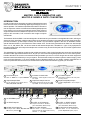
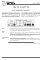
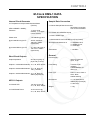
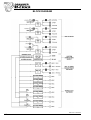
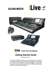
DRAWMER
M-Clock
DMS-1
MASTER CLOCK GENERATOR
AND MULTIPLE SAMPLE
RATE CONVERTER
CONTENTS
Warranty . . . . . . . . . . . . . . . . . . . . . . . . . . . . . . . . . . . . . . . . . . . . . . . . . . . . . . . . . . . 2
Safety Consideration . . . . . . . . . . . . . . . . . . . . . . . . . . . . . . . . . . . . . . . . . . . . . . . . . 3
Radio Frequencies Statement . . . . . . . . . . . . . . . . . . . . . . . . . . . . . . . . . . . . . . . . . 3
Chapter 1 - Introduction
Introduction . . . . . . . . . . . . . . . . . . . . . . . . . . . . . . . . . . . . . . . . . . . . . . . . . . . . . . . . 4
Installation . . . . . . . . . . . . . . . . . . . . . . . . . . . . . . . . . . . . . . . . . . . . . . . . . . . . . . . . 5
Installation and Connection Guide . . . . . . . . . . . . . . . . . . . . . . . . . . . . . . . . . . . . . 5
Chapter 2 - Control Description
Multiple Sample Rate Converter . . . . . . . . . . . . . . . . . . . . . . . . . . . . . . . . . . . . . . 6
Master Clock Generator . . . . . . . . . . . . . . . . . . . . . . . . . . . . . . . . . . . . . . . . . . . . . 7
Fig.1 THD +Noise Diagram . . . . . . . . . . . . . . . . . . . . . . . . . . . . . . . . . . . . . . . . . . 8
Chapter 3 - General Information
If a fault develops . . . . . . . . . . . . . . . . . . . . . . . . . . . . . . . . . . . . . . . . . . . . . . . . . 10
Contacting Drawmer . . . . . . . . . . . . . . . . . . . . . . . . . . . . . . . . . . . . . . . . . . . . . . . 10
Chapter 4 - DMS-1 Data
Specification . . . . . . . . . . . . . . . . . . . . . . . . . . . . . . . . . . . . . . . . . . . . . . . . . . . . . 11
Block Diagram . . . . . . . . . . . . . . . . . . . . . . . . . . . . . . . . . . . . . . . . . . . . . . . . . . . .12
COPYRIGHT
This manual is copyrighted 8 2002 by Drawmer Electronics Ltd. With all rights reserved. Under copyright
laws, no part of this publication may be reproduced, transmitted, stored in a retrieval system or translated
into any language in any form by any means, mechanical, optical, electronic, recording, or otherwise, without the written permission of Drawmer Electronics Ltd.
ONE YEAR LIMITED WARRANTY
Drawmer Electronics Ltd., warrants the Drawmer DMS-1
M-Clock master clock generator and sample rate converter
to conform substantially to the specifications of this manual
for a period of one year from the original date of purchase
when used in accordance with the specifications detailed
in this manual. In the case of a valid warranty claim, your
sole and exclusive remedy and Drawmer’s entire liability
under any theory of liability will be to, at Drawmer’s
discretion, repair or replace the product without charge, or,
if not possible, to refund the purchase price to you. This
warranty is not transferable. It applies only to the original
purchaser of the product.
For warranty service please call your local Drawmer dealer.
Alternatively call Drawmer Electronics Ltd. at +44 (0)1709
527574. Then ship the defective product, with transportation
and insurance charges pre-paid, to Drawmer Electronics
Ltd., Coleman Street, Parkgate, Rotherham, S62 6EL UK.
Write the RA number in large letters in a prominent position
on the shipping box. Enclose your name, address,
telephone number, copy of the original sales invoice and a
detailed description of the problem. Drawmer will not accept
responsibility for loss or damage during transit.
This warranty is void if the product has been damaged by
misuse, modification or unauthorised repair.
THIS WARRANTY IS IN LIEU OF ALL WARRANTIES,
WHETHER ORAL OR WRITTEN, EXPRESSED, IMPLIED
OR STATUTORY. DRAWMER MAKES NO OTHER
WARRANTY EITHER EXPRESS OR IMPLIED,
INCLUDING, WITHOUT LIMITATION, ANY IMPLIED
WARRANTIES OF MERCHANTABILITY, FITNESS FOR
A PARTICULAR PURPOSE, OR NON-INFRINGEMENT.
PURCHASER’S SOLE AND EXCLUSIVE REMEDY
UNDER THIS WARRANTY SHALL BE REPAIR OR
REPLACEMENT AS SPECIFIED HEREIN.
IN NO EVENT WILL DRAWMER ELECTRONICS LTD. BE
LIABLE FOR ANY DIRECT, INDIRECT, SPECIAL,
INCIDENTAL OR CONSEQUENTIAL DAMAGES
RESULTING FROM ANY DEFECT IN THE PRODUCT,
INCLUDING LOST PROFITS, DAMAGE TO PROPERTY,
AND, TO THE EXTENT PERMITTED BY LAW, DAMAGE
FOR PERSONAL INJURY, EVEN IF DRAWMER HAS
BEEN ADVISED OF THE POSSIBILITY OF SUCH
DAMAGES.
Some states and specific countries do not allow the
exclusion of implied warranties or limitations on how long
an implied warranty may last, so the above limitations may
not apply to you. This warranty gives you specific legal
rights. You may have additional rights that vary from state
to state, and country to country.
In the interests of product development, Drawmer reserve the right to modify or
improve specifications of this product at any time, without prior notice.
2
DRAWMER
M-Clock
For the USA
DMS-1
FEDERAL COMMUNICATIONS COMMISSION RADIO
FREQUENCY INTERFERENCE STATEMENT
MASTER CLOCK GENERATOR
AND MULTIPLE SAMPLE
RATE CONVERTER
SAFETY CONSIDERATIONS
CAUTION - MAINS FUSE
TO REDUCE THE RISK OF FIRE
REPLACE THE MAINS FUSE ONLY WITH
A FUSE THAT CONFORMS TO IEC127-2.
250 VOLT WORKING, TIME DELAY TYPE
AND BODY SIZE OF 20mm x 5mm.
THE MAINS INPUT FUSE MUST
BE RATED AT T315mA.
CAUTION - MAINS CABLE
DO NOT ATTEMPT TO CHANGE
OR TAMPER WITH THE
SUPPLIED MAINS CABLE.
CAUTION - SERVICING
DO NOT PERFORM ANY SERVICING.
REFER ALL SERVICING TO QUALIFIED
SERVICE PERSONNEL.
WARNING
TO REDUCE THE RISK OF FIRE OR
ELECTRIC SHOCK DO NOT EXPOSE
THIS EQUIPMENT TO RAIN OR MOISTURE.
This equipment has been tested and found to comply with
the limits for a Class B digital device, pursuant to Part 15
of the FCC Rules. These limits are designed to provide
reasonable protection against harmful interference in a residential installation. This equipment generates, uses and
can radiate radio frequency energy and, if not installed and
used in accordance with the instructions, may cause harmful interference to radio communications. However, there
is no guarantee that interference will not occur in a particular installation. If this equipment does cause interference
to radio or television reception, which can be determined
by turning the equipment off an on, then the user is encouraged to try to correct the interference by one or more
of the following measures:
Re-orient or relocate the receiving antenna.
Increase the separation between the equipment and
the receiver.
Connect the equipment into an outlet on a circuit
different from that to which the receiver is connected.
Consult the dealer or an experienced radio/TV
technician for help.
Unauthorised changes or modification to this system can
void the users’ authority to operate this equipment.
This equipment requires shielded interface cables in order
to meet FCC class B limit.
For Canada
CLASS B
NOTICE
This digital apparatus does not exceed the Class B limits
for radio noise emissions set out in the Radio Interference
Regulations of the Canadian Department of Communications.
CLASSE B
AVIS
Cet appareil numérique ne dépasse pas les limites de la
classe B au niveau des émissions de bruits radioélectriques
fixés dans le Règlement des signaux parasites par le
ministère Canadien des Communications.
3
CHAPTER 1
DRAWMER DMS-1
M-Cloc
k
M-Clock
MASTER CLOCK GENERATOR AND
MULTIPLE SAMPLE RATE CONVERTER
INTRODUCTION
In today's studio where increasing numbers of digital devices need
to be interconnected, maintaining digital signal integrity can be a
serious problem. The traditional professional solution has been to
use an expensive master clock that drives all the digital equipment
in the studio, but in most project studios there are often pieces of
equipment that don't have wordclock inputs such as consumer CD
players, MD recorders, DAT machines and budget computer
soundcards.
The Drawmer M-Clock DMS-1 has been designed to be the heart of syncronisation in the digital audio studio, offering an
extremely highly specified, multiple output master clock generator that also incorporates four further channels of sample-rate-conversion (a total output of twenty four Grade 1 synchronization signals in the form of AES/EBU, SPDIF,
optical Toslink and AES 11), all locked to the same master clock. The M-Clock generates seven Ultra Low Jitter sample
rates - 44.1k, 48k, 88.2k, 96k, 176.4k and 192k as well as 256x Superclock, all stable to < 1ppm. If any equipment in
the studio suffers jitter at its output the sample rate converters may be used to de-jitter and re-clock the signals before
further transmission.
The advantages of combining wordclock with multiple channels of 'clock-locked' sample rate conversion are significant
and often under-appreciated. With M-Clock, all your 'pro' and consumer digital equipment can run in the same system,
locked to the same clock, with no worries about finding a suitable sync source. You'll no longer have to switch equipment
between internal and external sync as you repatch - and the M-Clock helps to maintain optimum stereo imaging, lower
noise and lower distortion. If you have multiple pieces of digital equipment in your studio, whether professional or a
mixture of professional and consumer, the Drawmer M-Clock is the most effective upgrade you can make.
1
2
3
1 Front Panel Input:
4
2 4x Status Locked Leds:
either 1x S/PDIF or 1x optical TOSLINK
4 Output Sample Rate:
5 Output 5/6 sample rate x2:
13
11
10
7 2x AES/EBU Inputs:
8 1x S/PDIF Input:
10 4x SPDIF Outputs:
11 2x AES 11 XLR Outputs:
outputs to the AES 11 standard
(Also called DARS, Blank Frame).
13 8x BNC Clock Outputs:
the sample rate of 44.1k, 48k, 88.2k and
96k is set by switches 4 .
4
conveniently located on the front panel
for easy access.
6 Superclock (256x) Output:
doubles the sample rate as set by 4 upto 192k - for clock outputs 5 and 6.
12
14 5/6 x2 Clock Outputs:
when switch 5 is set to double the
output is twice the sample rate as set by
switches 4 , upto 192k.
6
3 4x Toslink Outputs:
indicates a locked signal for each of the
four inputs
the two switches set a sample rate of
44.1k, 48k, 88.2k and 96k.
15 14
5
provides Superclock to clock outputs 7
and 8.
9
8
7
9 4x AES/EBU Outputs:
12 2x AES 11 SPDIF Outputs:
outputs to the AES 11 standard.
(Also called DARS, Blank Frame).
15 7/8 Superclock (256x) Output:
when switch 6 is in, connectors 7/8
provide Superclock (256x) output.
INSTALLATION
The DMS-1 is designed for standard 19" rack mounting
and occupies 1U of rack space.Avoid mounting the unit
directly above power amplifiers or power supplies that
radiate significant amounts of heat.
If the unit is to be used in a mobile situation, it is strongly
recommended that the rear of the unit is supported in the
carrying rack to avoid bending the front panel rack mounting
‘ears’.
Always connect the mains earth to the unit. Use fibre or
plastic washers to prevent the front panel becoming marked
by the mounting bolts.
INSTALLATION AND CONNECTION GUIDE
5
CHAPTER 2
CONTROL DESCRIPTION
MULTIPLE SAMPLE RATE CONVERTER
Certain equipment in the studio may not have word clock
inputs which has in the past caused synchronisation
problems, using the four channels of high quality sample
rate conversion on the DMS1 M-CLOCK these digital audio
sources may be synched to the same ultra low jitter AES3
grade 1 stability master clock generator as the equipment
using the word clock or AES11 outputs from the DMS-1.
INPUT 4
Also if any equipment in the studio suffers jitter at its output
these sample rate converters may be used to de-jitter and
re-clock the signals before further transmission. Each
sample rate converter input is fed simultaneously to AES/
EBU, SPDIF and TOSLINK outputs solving any connectivity
problems and allowing signal distribution.
see fig.1
As well as the three inputs on the rear of the unit (2xAes/Ebu 1xSPDIF) two further sockets are
located on the front. These provide convenient access for the user to input from alternative sources,
and are selected between SPDIF and TOSLINK using the switch.
STATUS
1,2,3,4
The four LED’s indicate the status of the input sources, and correspond with the numbered input
connectors, 1 to 3 on the rear, and input 4 on the front.
When a led is lit continously a strong signal is being recieved by that input source and the M-Clock
is “locked on”. If a led flickers, the signal for that particular input source is weak or unstable - in this
case the source of this weak signal should be located and improved.
TOSLINK OUTPUTS
1,2,3,4
As well as the numerous outputs on the rear of the unit, four further TOSLINK sockets are located on
the front, providing convenient access for the user.
The numbers 1 to 4 correspond with the relavent input source i.e. Input source 3 (SPDIF on the rear)
has the TOSLINK output 3 etc.
See Fig 1. The Noise Floor of the Sample Rate Converters
6
Fig. 1 THD +Noise for Sample Rate Converter
7
MASTER CLOCK GENERATOR
The Drawmer M-Clock supplies word clock, S/PDIF, AES 11
grade 1, as well as Digidesign’s superclock (256x) allowing
you to synchronize Digidesign Pro Tools™, and a host of
other digital audio equipment through one stable and very
accurate unit.
The M-clock provides a wide range of sample rates from
44.1k upto 192k, as well as Superclock, all set using the front
OUTPUT SAMPLE RATE
RATE
Hi (x2)
panel switching. In addition upto three different sample rates
can be output at the rear of the unit, simultaneously, i.e. 96k
output from Word Clock outputs 1 to 4, 192k output from 5
and 6, and 256x superclock from 7 and 8. This feature allows,
for example, a DVD quality backup to be made whilst working
on Pro Tools™ simultaneously, making studio
synchronization easier than ever before.
The sample rate of the the unit is set using a combination of two switches, with the
resulting sample rate indicated by the corresponding led’s.
The RATE switch sets the base rate - either 44.1k, when the switch is out, or 48k, when in.
The Hi (x2) switch doubles the sample rate that is set by the RATE switch. i.e RATE is set to
48k (pressed in), Hi (x2) is pressed in - the resulting output sample rate is 96k.
The following output sample rates can be achieved:
RATE switch position
Hi (x2) switch position
Result
Out
Out
44.1 kHz
In
Out
48 kHz
Out
In
88.2 kHz
In
In
96 kHz
CLOCK OUTPUT OPTIONS
5/6
The 5/6 switch affects only connectors 5 and 6 on the BNC Clock Outputs on the rear of the
panel, working independantly from the other outputs, and can provide a maximum output
sample rate of 192k.
When pressed in the sample rate that is set by the RATE and Hi (x2) switches is doubled
i.e. Rate/Hi (x2) set the sample rate to 48k (Rate in/Hi out) - with 5/6 switch pressed in the
sample rate at the BNC output 5 and 6 is doubled to 96k even though the other outputs on
the M-Clock are still 48k. This would allow the user to have a workstation working at 48k
whilst similtaneously recording a DVD quality backup.
Output Sample Rate
8
5/6 Switched IN (x2)
44.1 kHz
88.2 kHz
48 kHz
96 kHz
88.2 kHz
176.4 kHz
96 kHz
192 kHz
7/8
When the 7/8 switch is active the M-Clock can output at the Superclock standard, as
used by Pro Tools™.
The 7/8 switch affects only connectors 7 and 8 on the BNC Clock Outputs on the rear of the
panel, working independantly from the other outputs.
Output Sample Rate
7/8 Switched IN (Superclock)
44.1 kHz
11.2896 mHz
48 kHz
12.288 mHz
88.2 kHz
11.2896 mHz
96 kHz
12.288 mHz
9
CHAPTER 3
GENERAL INFORMATION
IF A FAULT DEVELOPS
CONTACTING DRAWMER
For warranty service please call Drawmer Electronics Ltd.
or their nearest authorised service facility, giving full details
of the difficulty.
Drawmer Electronics Ltd., will be pleased to answer all
application questions to enhance your usage of this
equipment. Please address correspondence to:
A list of all main dealers can be found on the Drawmer
webpages.
Drawmer (Technical Help line)
Coleman Street
Parkgate
Rotherham
S62 6EL
UK
On receipt of this information, service or shipping
instructions will be forwarded to you.
No equipment should be returned under the warranty
without prior consent from Drawmer or their authorised
representative.
Alternatively contact us by E-mail on :
[email protected]
For service claims under the warranty agreement a service
Returns Authorisation (RA) number will be issued.
Write this RA number in large letters in a prominent position
on the shipping box. Enclose your name, address,
telephone number, copy of the original sales invoice and a
detailed description of the problem.
Authorised returns should be prepaid and must be insured.
All Drawmer products are packaged in specially designed
containers for protection. If the unit is to be returned, the
original container must be used. If this container is not
available, then the equipment should be packaged in
substantial shock-proof material, capable of withstanding
the handling for the transit.
10
Further information on all Drawmer dealers, Authorised
service departments and other contact information can be
obtained from our web pages on:
http://www.drawmer.com
CHAPTER 4
M-Clock DMS-1 DATA
SPECIFICATION
Internal Clock Generator
Sample Rate Conversion
2 x Temperature Compensated Xtal Oscillators
(TCXOs)
AES11 GRADE 1 Stability,
Tolerance
+/-1ppm (0-60
Celcius), <<+/-1ppm
(15-30 Celcius)
Phase noise
-130 dBc/Hz @ 1kHz
@ 24.5760 MHz to give Fs
48 kHz, 96 kHz &
192 kHz + 256Fs
(superclock)
@ 22.5792 MHz to give Fs
44.1 kHz, 88.2 kHz &
176.4 kHz + 256Fs
(superclock)
2 x Neutrik XLR AES/EBU inputs
1 x Phono SPDIF input
1 x Switchable Phono/TOSLINK input (Front Panel)
All outputs simultaneous on
4 x AES/EBU XLR,
4 x SPDIF Phono,
4 x TOSLINK
THD+Noise
> 120 dBFs
General
Word Clock Outputs
Output impedance
4 x Stereo Sample Rate Converters:
full up/down conversion
from 44.1kHz to 96kHz
Power Supply:
Internal, Universal
Input, 10 W
22.5 ohms giving 4v
pk-pk into 75 ohms
Fuse Rating
T315mA for All
voltages.
CONFORMING TO:
IEC127-2
Outputs 7-8 selectable between 44.1, 48, 88.2, 96,
256Fs (Superclock)
Fuse Type
20mm x 5mm, Class 3
Slow - Blow
250Volt working
AES 11 Outputs
Dimensions:
1u, 19" Rack Mount,
482mm(W) x 44mm(H)
x 145mm(D)
Weight
1.7 kg
Outputs 1-4 selectable between 44.1, 48, 88.2, 96 kHz
Outputs 5-6 selectable between 44.1, 48, 88.2, 96,
176.4, 192 kHz
2 x Neutrik XLR
2 x Gold Plated Phono
110 ohm source @
44.1, 48, 88.2, 96 kHz
75 ohm source @
44.1, 48, 88.2, 96 kHz
11
BLOCK DIAGRAM
Ref:1v01 C 29-03-05
12