1
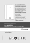
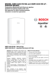
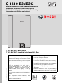
C 1210 ES/ESC
INDOOR RESIDENTIAL AND COMMERCIAL MODELS
Temperature Modulated with Electronic Ignition
Suitable for heating potable water and space heating
(Intended for variable flow applications)
C 1210 ES/ESC - Natural Gas
C 1210 ES/ESC - Liquefied Petroleum (LP) Gas
6 720 644 887 (2011/05) US
Warning: If the information in this manual is not
followed exactly, a fire or explosion may result
causing property damage, personal injury or death.
Do not store or use gasoline or other flammable
vapors and liquids in the vicinity of this or any other
appliance.
Improper installation, adjustment, alteration,
service or maintenance can cause injury or
property damage. Refer to this manual. For
assistance or additional information consult a
qualified installer, service agency or the gas
supplier.
In the Commonwealth of Massachusetts this
product must be installed by a licensed plumber or
gas fitter.
Upon completion of the installation, these
instructions should be handed to the user of the
appliance for future reference.
What to do if you smell gas
• Close gas valve. Open windows.
• Do not try to light any appliance.
• Do not touch any electrical switch; do not use any
phone in your building.
• Immediately call your gas supplier from a neighbor’s
phone. Follow the gas supplier’s instructions.
• If you cannot reach your gas supplier, call the fire
department.
• Installation and service must be performed by a
qualified installer, service agency or the gas supplier.
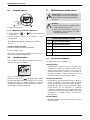
Index
Index
1
Warning
3
2
2.1
2.2
2.3
2.4
2.5
Appliance details
Features
Specifications (Technical data)
Unpacking the tankless water heater
General rules to follow for safe operation
Dimensions and minimum
installation clearances
5
5
5
6
8
3
3.1
3.2
3.3
3.4
3.5
3.6
3.7
3.8
3.9
3.10
3.11
3.12
3.13
3.14
Installation instructions
Specialized tools
Introduction
Venting
Combustion air requirements
Proper location for installing your heater
Heater placement and clearances
Mounting installation
Gas piping & connections
Water connections
Water quality
Filling the condensate trap
Domestic hot water recirculation
Space heating applications
Measuring gas pressure
10
10
10
10
24
25
25
25
26
29
29
31
32
33
35
Electrical connections
Electrical power supply
Position of the fuses in control unit
36
36
36
5
5.1
5.2
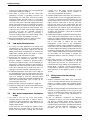
Operation instructions
Description of LCD Display
For your safety read before operating
your water heater
Power
Temperature selection
Use of optional remote control accessory
(part no. TSTAT2)
Operation
Reset button
Program button
Locked condition
37
37
5.6
5.7
5.8
5.9
2
Maintenance and service
Annual maintenance
Winterizing for seasonal use
Mineral scale build-up
Condensing heat exchanger unit
Adjusting CO2
Program values
Diagnostic menu
40
40
41
41
42
42
45
46
7
7.1
7.2
47
47
7.3
7.4
7.5
7.6
7.7
Troubleshooting
Introduction
Burner does not ignite when hot
water is turned on
Water is too hot
Water is not hot enough
Low water flow/pressure
Hot water temperature fluctuates at tap
Noisy burner/heater during operation
47
47
47
48
48
48
8
8.1
Error codes
Error code diagnostics
50
50
9
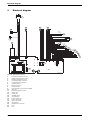
Electrical diagram
54
10
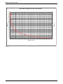
Sensor resistance charts
55
11
Functional scheme
57
9
4
4.1
4.2
5.3
5.4
5.5
6
6.1
6.2
6.3
6.4
6.5
6.6
6.7
38
38
38
39
39
39
40
40
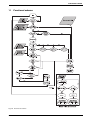
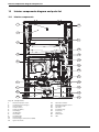
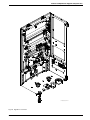
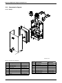
12
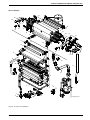
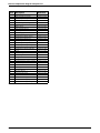
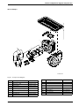
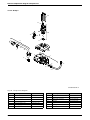
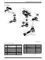
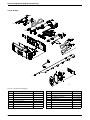
Interior components diagram
and parts list
12.1 Interior components
12.2 Components diagram
58
58
60
13
67
Protecting the environment
14
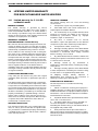
LIFETIME LIMITED WARRANTY
FOR BOSCH TANKLESS
WATER HEATERS
14.1 Limited warranty for C 1210 ES
residential model
14.2 Limited warranty for C 1210 ESC
commercial model
68
68
70
6 720 644 887
Warning
1
Warning
For your safety
Do not store or use gasoline or other flammable,
combustible or corrosive vapors and liquids in the
vicinity of this or any other appliance.
Warning: Carefully plan where to
install the heater. Correct combustion
air supply and flue pipe installation are
very important. If a gas appliance is not
installed correctly, fatal accidents can
result such as carbon monoxide
poisoning or fire.
Warning: Exhaust gas must be vented
to outside using approved vent material
See table 2, page 11 (For Canada use
only PVC ULC S636). Vent and
combustion air connector piping must
be sealed gas-tight to prevent
possibility of flue gas spillage, carbon
monoxide emissions and risk of fire,
resulting in severe personal injury or
death. Approved vent terminators must
be used when penetrating to the
outside.
Warning: Field wiring connections and
electrical grounding must comply with
local codes, or in the absence of local
codes, with the latest edition of the
National Electric Code, ANSI/NFPA 70,
or in Canada, all electrical wiring must
comply with the local codes and the
Canadian Electrical Code, CSA C22.1
Part 1.
Warning: Shock hazard: line voltage is
present. Before servicing the water
heater, unplug power supply cord from
outlet. Failure to do so could result in
severe personal injury or death.
Warning: The heater must be
disconnected from the gas supply
piping system during any pressure
testing of that system at test pressures
equal to or more than 0.5 psig.
Warning: The appliance should be
located in an area where water leakage
of the heat exchanger, piping or
connections will not result in damage to
the area adjacent to the appliance or to
lower floors of the structure. When such
locations cannot be avoided, it is
recommended that a suitable drain pan,
adequately drained, be installed under
the appliance. The pan must not restrict
combustion air flow.
Warning: The maximum inlet gas
pressure must not exceed the value
specified by the manufacturer and the
minimum value listed is for the purpose
of input adjustment.
Warning: If a water heater is installed in
a closed water supply system, such as
one having a backflow preventer in the
cold water supply line, means shall be
provided to control thermal expansion.
Contact the water supplier or local
plumbing inspector on how to control
this situation.
Warning:
B Every time there is a demand for hot
water the tankless must recognize the
activation flow, activate the burners, and
raise the temperature to the set point
temperature.
B The time to reach set temperature
depends upon the inlet temperature, the
distance to the tap and the water flow.
B Usage patterns with short duration
draws may not give the tankless the time
to reach the desired temperature.
Examples are commercial kitchen
sprayers and some dishwashers with
short cycles.
B In such applications a small buffer tank
may be needed to improve performance.
Contact Bosch Water Heating for
additional information.
Warning: Keep the appliance area
clear of combustible materials, gasoline
and other flammable vapors and liquids.
6 720 644 887
3
Warning
Warning: Do not obstruct the flow of
combustion and ventilation air.
DANGER
Warning: When manually operating the
relief valve, precautions must be taken
prior to operating the relief valve to avoid
contact with hot water coming out of the
relief valve and to prevent water
damage.
HOT
BURN
Caution: Label all wires prior to
disconnection when servicing controls.
Wiring errors can result in improper and
dangerous operation.
Verify proper operation after servicing.
Water temperature over 125°F can
cause severe burns instantly or
death from scalds.
Children, disabled and elderly are
at highest risk of being scalded.
Warning: If a relief valve discharges
periodically, this may be due to thermal
expansion in a closed water supply
system. Contact the water supplier or
local plumbing inspector on how to
correct this situation. Do not plug the
relief valve.
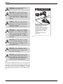
See instruction manual before
setting temperature at water
heater.
Feel water before bathing or
showering.
Fig. 1
Warning: If the water heater is used in
a space heating application, all piping
and components connected to the
water heater must be suitable for use
with potable water.
Warning: Toxic chemicals, such as
those used for boiler treatment, shall not
be introduced into the potable water
used for space heating.
Warning: A water heater which will be
used to supply potable water shall not
be connected to any heating system or
component(s) previously used with a
nonpotable water heating appliance.
FCC:
This device complies with Part 15 of the FCC rules.
Operation is subject to the following two conditions: (1)
This device may not cause harmful interference, and (2)
this device must accept any interference received,
including interference that may cause undesired operation.
4
6 720 644 887
Appliance details
2
Appliance details
• Pipe Cover (PTPCES)
• Recess box kit (7736500043)
2.1
Features
Residential/commercial models
• C 1210 ES residential model
– maximum temperature 140° F
• Pressure relief valve (FWL-2).
i
BOSCH is constantly improving its
products, therefore specifications are
subject to change without prior notice.
• C 1210 ESC commercial model
– maximum temperature 180° F
2.2
Parts
Approved in US/Canada
• Key pad interface control
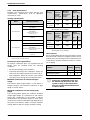
Capacity
• High power pre-mix compact burner with low NOx
emissions
Maximum flow rate: 9.2 GPM (35 l/min) at a 45°F
(25°C) rise. (with sufficient water pressure)
• Modulating gas valve with constant gas:air ratio
control
Maximum output
• Modulating water valve for improved comfort and
temperature control.
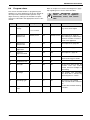
Specifications (Technical data)
210,000 Btu/h (61.5 kW)
Maximum input
High quality materials for long working life
225,000 Btu/h (65.9 kW)
• Copper heat exchanger
Efficiency in %
• High efficiency Ceramat Burner
Thermal efficiency > 94%
• Compact space saver: mounts on a wall with
supplied bracket.
Minimum Input
Features
25,000 Btu/h (7.3 kW)
• Easily removable one-piece cover
Temperature Control
• LCD Display with backlight
C 1210 ES:
• On/Off and Temperature control buttons
• Selection range: 100°F (38°C) - 140°F (60°C).
• Reset button
C 1210 ESC:
• Program button (Selectable temperature default)
• Selection range: 100°F (38°C) - 180°F (82°C).
• Error codes for easy diagnostics and repair
Default temperature: 122°F (50°C)
• Real-time diagnostics for troubleshooting/informational purposes
Stability: +/- 2°F (+/- 1°C)
• Built in freeze prevention.
Gas Requirement
Gas connection (inches) - ¾"
Note: The freeze prevention kit is designed to provide
protection for the water heater down to approximately
5°F for short term conditions only. It will not protect the
appliance in areas where the temperature is routinely
expected to be below freezing.
- The freeze prevention kit will not protect plumbing outside the appliance from freezing. Precautions should be
taken.
Inlet gas pressure under operation (with a high hot
water flow rate)*
Accessories (Bosch part #)
Water
• Optional wireless remote control to operate with the
appliance (TSTAT2)
• Cascading kit (77090003962)
• Outdoor kit (BTOK)
• External water filter (part # 8 703 305 356)
• Concentric termination kit (196016)
• Propane: 8" - 13" water column
• Natural Gas: 3.5" - 10.5" water column.
* To measure Gas Pressure, see Measuring Gas
Pressure, chapter 3.14, page 35.
• Hot water connection (inches) - ¾"
• Cold water connection (inches) - ¾"
• Water valve material: Polymer (PPS) (Polypropylene
Sulfid)
• Minimum water flow: 0.5 gallon/minute (1.9 l/m)
Note: Activation varies with inlet water temperatures
from 0.5 - 1.6 gallon/minute (1.9 - 6.1 l/m).
• Exhaust/Intake bird screen (L2594)
6 720 644 887
5
Appliance details
• Minimum recommended water pressure: 30 PSI
(2.07 bar)
• Minimum well pressure 40 psi, see page 29.
• Connections:
– Bottom of heater
Combustion
2.3
Unpacking the tankless water
heater
Before installing the unit, be certain you have the
correct heater for your type of Gas - Propane or
Natural Gas. Identification labels are found on the
shipping box, and on the rating plate which is located on
the right side panel of the cover.
• NOx ≤ 14 Ng/J (Nanograms of NOx (calculated as NO2)
per Joule of heat output)
• CO ≤ 290 ppm (measured)
• CO2 level set from factory, see chapter 6.5, page 43.
Dimensions
• Depth (in): 11¼" (286 mm)
• Width (in): 17 7/8" (452 mm)
• Height (in): 30½" (775 mm)
• Weight: 88 pounds (40 kg).
Gas types
Natural Gas.
LP Gas.
Fig. 2
A
B
Rating plate
Serial number
Type of gas
Voltage
The box includes:
120 V AC (60 Hz) nominal
• Tankless water heater
Amperage
• Bracket for wall hanging the heater
Idle - 40 mA
Operation - ≤ 2.5 A
• Exhaust vent adaptor (with 4 screws and gasket
provided)
Noise
• Combustion air inlet adaptor (with 3 screws and gasket provided)
45 - 65 db (A)
Safety devices
• Installation manual (manual can be downloaded from
www.bosch-climate.us)
• Flame failure device (ionization flame rod sensor)
• Product registration card.
• Overheat prevention (temperature limiter/ECO)
Please complete and return the enclosed product
registration card.
• Outlet temperature sensor
• Backflow temperature sensor
• Exhaust gas temperature sensor.
Water protection
IP X4 (protection against water drops)
i
If appliance is installed at elevations above
2000ft, refer to table 18, page 21.
The tankless water heater is not approved or
designed for:
• Manufactured (mobile) homes, boats or any
mobile installation. (Modular homes are
acceptable for installation).
• Use above 8000 ft A.S.L. altitude (see page 21).
• Outdoor installation without installation of
Outdoor kit (BTOK).
• Applications where inlet water temperature is
higher than 140°F (60°C). A thermostatic
mixing valve must be installed before the
appliance.
6
6 720 644 887
Appliance details
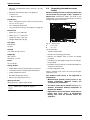
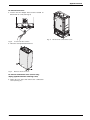
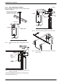
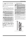
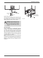
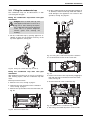
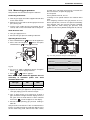
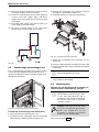
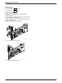
To remove front cover
B Loosen the two Phillips head screws located on
bottom rear of cover (see Fig. 3).
6720644956-11.1V
Fig. 5
Fig. 3
Remove the combustion cover
Loosen the two screws
B Lift front cover upward and remove.
Fig. 4
Remove the front cover
To remove combustion cover (service only;
unplug appliance before removing cover)
B Open the four clips and remove the combustion
cover (see Fig. 5).
6 720 644 887
7
Appliance details
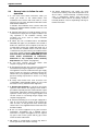
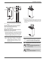
2.4
General rules to follow for safe
operation
B 1. You must follow these instructions when you
install your heater. In the United States: The
installation must conform with local codes or, in the
absence of local codes, the National Fuel Gas Code
ANSI Z223.1/NFPA 54.
In Canada: The Installation must conform with CSA
B149.(1,2) INSTALLATION CODES and /or local
installation codes.
B 11. Water temperatures over 125°F can cause
severe burns instantly. If the outlet temperature is set
above 125°F, a thermostatically controlled mixing
valve or temperature limiting valve should be
considered to reduce the risk of scalding. Contact a
licensed plumber or the local plumbing authority for
further information.
B 2. Carefully plan where to install the heater. Correct
combustion air supply and vent pipe installation are
very important. If not installed correctly, fatal
accidents can occur, such as carbon monoxide
poisoning or fire.
B 3. When the unit is installed indoors and ROOM
SEALED (twin pipe) it is permitted to be located in
bathrooms, bedrooms and occupied rooms that are
normally kept closed. See chapter 3.3 (page 10). If
the unit will be installed indoors and use indoor
combustion air, the place where you install the heater
must have enough ventilation. The National Fuel
Gas Code does not allow UNSEALED gas fired
water heater installations in bathrooms,
bedrooms or any occupied rooms normally
kept closed. See chapter 3.4 (page 24).
B 4. You must correctly vent your heater. See
chapter 3.3 (page 10) on VENTING.
B 5. The appliance and its gas connection must be leak
tested before placing the appliance in operation.
The appliance must be isolated from the gas supply
piping system by closing its individual manual gas
shutoff valve (not supplied with heater) during any
pressure testing at pressures in excess of ½ Psig
(3.5 kPa).
B 6. Keep water heater area clear and free from
combustibles and flammable liquids. Do not locate
the heater over any material which might burn.
B 7. Correct gas pressure is critical for the proper
operation of this heater. Gas piping must be sized to
provide the required pressure at the maximum output
of the heater, while all the other gas appliances are in
operation. Check with your local gas supplier, and
see the section on connecting the gas supply. See
chapter 3.8 (page 26).
B 8. Should overheating occur or the gas supply fail to
shut off, turn off the gas supply at the manual gas
shut off valve, on the gas line. Note: manual gas
shutoff valve is not supplied with the heater but must
be field installed.
B 9. Do not use this appliance if any part has been
underwater. Immediately call a qualified service
technician to inspect the appliance and to replace
any part of the control system and any gas control
which has been underwater.
B 10. Failure to install heater correctly may lead to
unsafe operation and void the warranty.
8
6 720 644 887
Appliance details
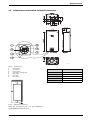
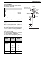
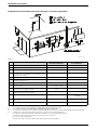
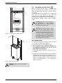
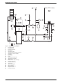
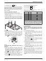
Dimensions and minimum installation clearances
6
2.5
4
6720608000-03.2AL
Fig. 6
1
2
3
4
5
6
7
Dimensions
On/Off button
Reset button
Program button
Power ON or stand-by LED
LCD display
Up button
Down button
Model C 1210 ES
TOP (A)
12"
FRONT (B)
1"
BACK
0"
SIDES
1"
FLOOR (C)
12"
Table 1 Minimum clearances
Fig. 7
Minimum clearances
Note: For servicing access, a 2 foot clearance is
recommended to the front cover.
6 720 644 887
9
Installation instructions
3
Installation instructions
3.1
Specialized tools
3.3
Venting
The following specialized tools may be required for
installation:
Warning:
• Manometer
B Do not reduce the exhaust
combustion air vent pipe sizes.
• Multi-meter
or
• Combustion Gas Analyzer.
B Do not common vent with any other
vented appliance or stove.
3.2
B Do not use Type-B vent as the actual
exhaust vent system for the appliance.
Introduction
Please follow these instructions. Failure to follow
instructions may result in:
B Damage or injury.
B Improper operation.
B Loss of warranty.
Warning:
The water heater must be installed by a
qualified installer in accordance with these
instructions. If improperly installed, a
hazardous condition such as explosion or
carbon monoxide poisoning could result.
Bosch Thermotechnology Corp. is not
responsible for improperly installed
appliances.
i
10
Common installation practice is to
first
determine
the
venting/
combustion air point of termination,
then design the piping layout back to
the heater.
Warning: Failure to vent the exhaust
gases to the outside (see Table 2 for
proper material) may result in
dangerous flue gases filling the
structure in which it is installed.
Warning: In areas where outside
temperatures routinely come close to
freezing, sealed combustion operation
is required. Concentric termination or
separate terminations for combustion
and vent, must be installed on the same
wall or roof surface; however, never
facing the direction of prevailing winds.
Failure to do so may result in heat
exchanger freezing and bursting. This
failure is not covered under the
manufacturer's warranty.
Warning: Protect the exhaust and inlet
from leaves and debris by installing a
screen on the end of the terminator.
¼" mesh minimum opening
recommended on screen.
6 720 644 887
Installation instructions
3.3.1
Vent material
All combustion air and vent pipe materials and fittings
must comply with the following:
Item
Vent or
air pipe
and
fitting
Material
United States
PVC schedule 40
ANSI/ASTM D1785
PVC-DWV
ANSI/ASTM D2665
CPVC schedule 40
ANSI/ASTM F441
ABS-DWV schedule 40 ANSI/ASTM D2661
PVC
Pipe
cement / CPVC
primer
ABS
Canada
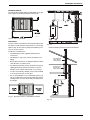
MAINTAIN 12 IN. (18 IN. FOR CANADA)
MINIMUM CLEARANCE ABOVE
HIGHEST ANTICIPATED SNOW LEVEL.
MAXIMUM OF 24 IN. ABOVE ROOF.
EXHAUST
COMBUSTION
AIR
ROOF BOOT/
FLASHING (FIELD
SUPPLIED
CONCENTRIC
VENT KIT
(BWH60L46)
CSA or ULC
certified only
(ULC-S636)
ANSI/ASTM D2564
ANSI/ASTM F493
INTAKE
ANSI/ASTM D2235
EXHAUST
3" (76mm)
Table 2 Approved vent material
For specific questions concerning vent material,
specifications, usage or installation, please
contact the vent manufacturer directly.
i
3" (76mm)
DRAIN TEE
Do not use cellular foam core pipe.
All vent connections must be glued, except for the
exhaust accessory (see section 3.3.4) which is
screwed into place on the top of the appliance. Slide
the vent pipe into the exhaust accessory. The exhaust
pipe must be properly supported and must be pitched
a minimum of a ¼ inch per foot back to the appliance.
This allows the condensate to drain properly.
6720608836-27.2V
Fig. 8
Concentric vent kit example
An optional concentric vent/air intake termination can
be used for the installation of a vertical or horizontal
venting system. (see Fig. 8).
The concentric vent/air intake body can be ordered
from your local wholesaler. (Part# 196016).
The appliance can also be installed with separate air
intake and exhaust piping (see Fig. 11, Fig. 18 and Fig.
19, page 18).
Description
Length
Kit part no. and
quantity
196016
3- In. Rain Cap
N/A
1
4- In. Diameter
SDR-26 Pipe
24 In. long
1
N/A
1
3- In. Y
Concentric Fitting
2- ½ In. Diameter
37-1/8 in. long
SDR-26 Pipe
1
3- In. Condensate
drain Tee
N/A
1
1.5- In. Condensate drain bushing
N/A
1
Table 3 Concentric vent part breakdown
6 720 644 887
11
Installation instructions
3.3.2
Vent specifications
Establish vent clearances that comply with the vent
manufacturer's specifications and all applicable
national/local codes.
3"
Venting
Maximum
allowable
Exhaust
pipe length
Maximum
allowable
Combustion
air pipe
length
Elbow
Equivalency
90°
45°
Venting specifications
Diam.
Aproved terminals
“T” terminal
E
x
h
a
u
s
t
90° elbow
3 or 4 inches
PVC Flue Cap*
(ECAP321)
Vertical terminations only
3" diameter only
Twin pipe
system
31ft
31ft
5 ft
3 ft
Concentric system
23ft
23ft
5 ft
3 ft
Table 5 Maximum Allowable Exhaust and Combustion
Air Lengths for 3" venting
4"
Venting
Maximum
allowable
Exhaust
pipe length
Concentric
(196016)
“T” terminal
I
n
t
a
k
e
90° elbow
3 or 4 inches
PVC Flue Cap*
(ECAP321)
Vertical & horizontal terminations approved
3" diameter only
Concentric
(196016)
Table 4 Venting specifications for intake and exhaust
*
ULC S636-95, UL1738 certified
Condensate drain requirements
An external condensate drain (not supplied with the
heater) must be installed under the following
conditions:
Maximum
allowable
Combustion
air pipe
length
Elbow
Equivalency
90°
45°
Twin pipe
system
63ft
63ft
2.5ft
1.5ft
Concentric system
23ft
23ft
2.5ft
1.5ft
Table 6 Maximum Allowable Exhaust and Combustion
Air Lengths for 4" venting
Use of elbows
It is recommended to limit the amount of elbows used in
the exhaust and combustion air piping to reduce friction
in the air flow. The following lists the maximum amount
of 90° elbows allowed in either the exhaust or combustion air piping:
Max. number of 90°
elbows
3"
venting
4"
venting
Twin pipe system
5
7
Concentric system
4
6
• All vertical terminating vent installations.
• Horizontal terminating vent installations where the
total linear vent length is greater than 6 feet (1.8 m).
• Vent installations where any section of the exhaust
vent pipe passes through an unconditioned space.
Minimum combustion air and exhaust pipe
length
The minimum exhaust pipe length is 1 feet (0.3m) of
straight vent pipe. The minimum combustion air pipe
length is one 90° elbow.
Table 7
i
Two 45° elbows are equal to one 90°
elbow. Any combination of 45° and
90° elbows may be used in the vent
system as long as the combination
does not exceed the maximum listed
in table 7 above.
Maximum combustion air and exhaust pipe
length
The following tables display the maximum allowable
straight pipe lengths for combustion air and exhaust
piping with consideration to the number of elbows
used. Reduce the equivalent length for each elbow
used from the maximum allowable length depending on
the system used. Refer to table 5 if using 3" diameter
venting. Refer to table 6 if using 4" diameter venting.
12
6 720 644 887
Installation instructions
Calculation example for 3" venting:
Calculation example for 4" venting:
Exhaust
Exhaust
System used
Concentric
System used
Twin pipe
Number of 90° elbows needed:
1
Number of 90° elbows needed:
1
Number of 45° elbows needed:
2
Number of 45° elbows needed:
2
Table 8
Table 12
Calculation of example
Calculation of example
Max. length
23’
Max. length
90° elbow reduction
- 5’
90° elbow reduction
sub-total =
45° elbow reduction
18’
- 6’
Total =
- 2.5’
sub-total =
45° elbow reduction
61.5’
- 3’
12’
Table 9
i
63’
Total =
58.5’
Table 13
For this example, the maximum allowable
exhaust pipe length is 12 feet.
Combustion air
i
For this example, the maximum allowable
exhaust pipe length is 58.5 feet.
Combustion air
System used
Concentric
System used
Twin pipe
Number of 90° elbows needed:
2
Number of 90° elbows needed:
2
Number of 45° elbows needed:
1
Number of 45° elbows needed:
2
Table 10
Table 14
Calculation of example
Calculation of example
Max. length
23’
Max. length
63’
90° elbow reduction
- 10’
90° elbow reduction
- 5’
sub-total =
45° elbow reduction
13’
- 3’
Total =
45° elbow reduction
10’
Table 11
i
sub-total =
58’
- 3’
Total =
55’
Table 15
For this example, the maximum allowable
combustion air pipe length is 10 feet.
6 720 644 887
i
For this example, the maximum allowable
combustion air pipe length is 55 feet.
13
Installation instructions
Required direct vent terminal clearances (twin pipe / concentric penetration)
6720608836-23.1Av
Fig. 9
Canadian installations1)
U.S. installations2)
A
Clearance above grade, veranda, porch, deck or balcony
12 in.
12 in.
B
Clearance to window or door that may be opened
36 in.
12 in.
C
Clearance to permanently closed window
*
*
D
Vertical clearance to ventilated soffit located above the vent
terminator within a horizontal distance of 2 feet (61cm) from the
center line of the terminator
*
*
E
Clearance to unventilated soffit
*
*
F
Clearance to outside corner
*
*
G
Clearance to inside corner
*
*
H
Clearance to each side of center line extended above meter/
regulator assembly
36 in. within a height 15 feet above
meter/ regulator assembly
*
I
Clearance to service regulator vent outlet
36 in.
*
J
Clearance to non-mechanical air supply inlet to building or the
combustion air inlet to any other application
36 in.
12 in.
K
Clearance to mechanical air supply inlet
72 in.
36 in. above if within 10 feet
horizontally
L
Clearance above paved sidewalk or paved driveway located on
public property
84 in. 3)
*
M
Clearance under veranda, porch deck or balcony
12 in. 4)
*
Table 16
1)
2)
In accordance with the current CSA B149.1 Natural Gas and Propane Installation Code
In accordance with the current ANSI Z223.1 / NFPA 54 National Fuel Gas Code
3)
4)
A vent shall not terminate directly above a sidewalk or paved driveway that is located between two single family dwellings and serves both dwellings.
Permitted only if veranda, porch, deck or balcony is fully open on a minimum of two sides beneath the floor.
*
For clearances not specified in ANSI Z223.1 / NFPA 54 or CSA-B149.1, one of the following shall be indicated:
a) A minimum clearance value determined by testing in accordance with section 2.20, or;
b) A reference to the following footnote:
“Clearance in accordance with local installation codes and the requirements of the gas supplier.”
14
6 720 644 887
Installation instructions
Required other than direct vent terminal clearances (single pipe penetration)
6720608836-23.1Av
Fig. 10
Canadian installations1)
U.S. installations2)
A
Clearance above grade, veranda, porch, deck or balcony
12 in.
12 in.
B
Clearance to window or door that may be opened
36 in.
4 feet below or to side of opening;
1 foot above opening
C
Clearance to permanently closed window
*
*
D
Vertical clearance to ventilated soffit located above the vent
terminator within a horizontal distance of 2 feet (61cm) from the
center line of the terminator
*
*
E
Clearance to unventilated soffit
*
*
F
Clearance to outside corner
*
*
G
Clearance to inside corner
*
*
H
Clearance to each side of center line extended above meter/
regulator assembly
36 in. within a height 15 feet above
meter/ regulator assembly
*
I
Clearance to service regulator vent outlet
36 in.
*
J
Clearance to non-mechanical air supply inlet to building or the
combustion air inlet to any other application
36 in.
4 feet below or to side of opening;
1 foot above opening
K
Clearance to mechanical air supply inlet
72 in.
36 in. above if within 10 feet
horizontally
L
Clearance above paved sidewalk or paved driveway located on
public property
84 in. 3)
84 in.
M
Clearance under veranda, porch deck or balcony
12 in. 4)
*
Table 17
1)
2)
In accordance with the current CSA B149.1 Natural Gas and Propane Installation Code
In accordance with the current ANSI Z223.1 / NFPA 54 National Fuel Gas Code
3)
4)
A vent shall not terminate directly above a sidewalk or paved driveway that is located between two single family dwellings and serves both dwellings.
Permitted only if veranda, porch, deck or balcony is fully open on a minimum of two sides beneath the floor.
*
For clearances not specified in ANSI Z223.1 / NFPA 54 or CSA-B149.1, one of the following shall be indicated:
a) A minimum clearance value determined by testing in accordance with section 2.20, or;
b) A reference to the following footnote:
“Clearance in accordance with local installation codes and the requirements of the gas supplier.”
6 720 644 887
15
Installation instructions
3.3.3
Vent configuration examples
MINIMUM
1”
Below are approved examples of vertical and horizontal
venting installations.
MAINTAIN 12 IN. (18 IN. FOR CANADA)
MINIMUM CLEARANCE ABOVE
HIGHEST ANTICIPATED SNOW LEVEL.
MAXIMUM OF 24 IN. ABOVE ROOF.
3" (80mm)
3" (80mm)
INTAKE
EXHAUST
DRAIN TEE
EXHAUST
COMBUSTION
AIR
EXHAUST
3" (80mm)
INTAKE
6720608643-11.2V
DRAIN TEE
Fig. 13 Horizontal venting system (concentric vent)
6720608836-24.2V
Fig. 11 Vertical venting system (single pipe penetration)
4"
Fig. 14 Horizontal parallel venting system (twin pipe
direct vent)
HORIZONTAL RUN
DOWN TO
TERMINATOR.
NOTE:
MINIMUM 1FT OF
STRAIGHT VENT PIPE
REQUIRED
6720608836-25.1Av
SIDE
OF
WATER
HEATER
6720608542-10.1V
Fig. 12 Horizontal venting installation (combustion air
piping not shown)
* Warning: Single pipe penetration should be used in
non-freezing climates only!
16
6 720 644 887
Installation instructions
3" (80mm)
EXHAUST
INTAKE
4” Min.
DRAIN TEE
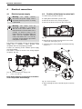
Fig. 16 Exhaust connection
6720608643-12.2V
B Attach the combustion air inlet accessory to the top
of the unit Fig. 17 (position 2) using the 3 screws and
gasket provided, and install 3" air intake pipe over the
accessory.
Fig. 15 Horizontal venting system (single pipe penetration)
*Warning: Single pipe penetration should be
used in non-freezing climates only!
3.3.4
Vent connections
Attaching the exhaust and air inlet connection
adaptors to the top of the heater
B Attach the flue gas exhaust accessory to the top of
the unit Fig. 16 (position 1) using the 4 screws and
gasket provided, and fully insert vent pipe into the
accessory. If using 4" venting, a 3" to 4" increaser
should be installed directly after this accessory.
i
NOTE: Vent pipe must be completely
vertical when inserting or blue gasket
inside exhaust accessory can become
displaced. Exhaust accessory can be
removed with vent pipe attached to check
gasket position.
Fig. 17 Inlet connection
i
3.3.5
NOTE: The combustion air accessory can
be installed on the top right or on the top
left side of the heater. The combustion air
inlet that is not used must be kept sealed.
Connecting the condensate water drain
Warning:
B Failure to properly install condensate
drain can damage the appliance and will
void the warranty.
Warning:
B Do not install condensate drain tubing in
areas where it may freeze.
6 720 644 887
17
Installation instructions
i
i
The condensate must be disposed of in
accordance with local codes.
See chapter 3.11 “Filling the condensate
trap”.
• 3. To install condensate drain in vent system, use
PVC 3" X 3" X 1.5" tee and reduce for drain
connection.
Use materials approved by the authority
having jurisdiction. In the absence of other
authority, PVC, and CPVC pipe must
comply with ASTM D1785, F441 or
D2665. Cement and primer must comply
with ASTM D2564 or F493. For Canada,
use CSA or ULC certified PVC or CPVC
pipe, fittings and cement, see table 2.
4” Min.
Condensate drain
Appliance condensate drain installation
The appliance comes equipped with an internal
condensate drain and siphon. This drains condensation
formed in the secondary heat exchanger. Piping must
be installed under the condensate drain outlet on the
water heater and piped for disposal in accordance with
local codes.
Dispose of condensate in
accordance with local codes
6720608643-17.2V
Fig. 19 External condensate drain installation
3.3.6
Leave min. ¼" air gap
1 ½" x ¾" PVC Reducer
Trap required
Fig. 18 Appliance drain installation
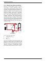
Freeze prevention
In cold climates, components of a tankless water heater
can freeze and burst from negative draft. A leading
cause of negative draft is combustion appliances in the
building not being supplied with sufficient combustion
air. A wood stove or furnace can pull its combustion air
from the water heater‘s vent pipe, allowing the cold
incoming air to freeze the cold water in the heat
exchanger. Supplying more combustion air for all combustion appliances is the solution. A HVAC specialist
should be consulted to design solutions for providing
more combustion air.
Listed below is an additional measure designed to further limit backdraft in extreme conditions assuming all
other possible causes have been addressed.
External condensate drain installation
If an external condensate drain (installer supplied) must
be installed (Section 3.3.2), the following is
recommended:
• 1. Install condensate drain on a horizontal section of
the exhaust pipe as close to the heater as possible.
• 2. The condensate must be disposed of according to
local codes.
18
6 720 644 887
Installation instructions
Backdraft reducer
The Heat Fab backdraft reducer (9301BFP) is the preferred option for limiting backdraft (see Fig. 20).
6720608643-18.1V
Fig. 20 Part nr 9301BFP
Installation
6720608542-06.2V
For this solution to be effective, the internal flapper must
be 100% closed when the water heater is not running.
Refer to Fig. 22 and 23 for preferred installation positions in the vent system.
Fig. 22
Preferred damper position for vertical terminations
Installation considerations:
• Install damper per the supplied manufacturer‘s
instructions.
• The damper is only to be used in the exhaust vent
piping.
Unconditioned
space. Do not
install damper.
• Ensure directional arrow on damper label faces in the
same direction as exhaust flow.
• If installed horizontally, the axis must be horizontal or
slightly pitched up towards termination to ensure
damper closes 100% when heater is not running.
Enclosed vent
pipe. Do not
install damper.
• To allow accessibility, damper must not be installed
in an enclosed section of vent pipe.
• Do not install damper in unconditioned spaces (e.g.
attics) Condensation can build up while the heater is
running which can later freeze and potentially block
the flapper.
6720608643-19.1V
Fig. 21 Blackflow reducer (9301BFP) installed
6720608836-30.2V
Fig. 23
6 720 644 887
19
Installation instructions
3.3.7
Fan speed adjustment
! IMPORTANT INFORMATION:
Natural gas heaters with installation altitudes
below 2,000 ft above sea level disregard this
section.
Installation adjustment:
After installing the tankless water heater, the fan speed
values for minimum power (P2) and maximum power
(P1) may need adjustment due to variations in altitude
and vent pipe length. Failure to make necessary
adjustments to fan speed values may result in improper
operation of the appliance.
First calculate the total equivalent vent length. Use This
is the straight pipe length of both exhaust and combustion air plus the number of elbows used. To determine
the length equivalency of each elbow refer to tables 5
and 6.
Use the equivalent vent length value to determine the
appropriate fan speed values found in table 18 and 19.
Refer to page 22 on how to adjust the fan speeds if an
adjustment is necessary. After changing fan speed values, proceed to section 6.5 to confirm CO2 values are
within specified ranges.
20
6 720 644 887
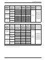
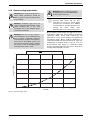
Installation instructions
Altitude
(above sea
level)
0 - 2000 ft
(0 - 610 m)
2000 - 4500 ft
(610 - 1372 m)
4500 - 8000 ft
(1372 - 2439 m)
Table 18
1)
Vent
terminal
Concentric
Twin
system
Concentric
Twin
system
Concentric
Twin
system
NG
LPG
NG/LPG
Minimum
power fan
speed (P2)
12
12
12
12
12
13
12
13
13
13
13
13
Minimum
power fan
speed (P2)
12
13
12
14
14
14
13
14
14
15
14
15
Maximum
power fan
speed (P1)
NG
LPG
NG/LPG
Total equivalent
vent length1)
Minimum
power fan
speed (P2)
Minimum
power fan
speed (P2)
Maximum
power fan
speed (P1)
3.5 - 25 ft
12
12
26 - 46 ft
12
13
3.5 - 59 ft
12
12
60 - 126 ft
12
14
3.5 - 25 ft
12*
14*
26 - 46 ft
13*
14*
3.5 - 59 ft
12*
13*
60 - 126 ft
13*
14*
3.5 - 25 ft
13*
14*
26 - 46 ft
13*
14*
3.5 - 59 ft
13*
14*
60 - 126 ft
13*
15*
Total equivalent
vent length1)
6 - 25 ft
26 - 46 ft
6 - 37 ft
38 - 62 ft
6 - 25 ft
26 - 46 ft
6 - 37 ft
38 - 62 ft
6 - 25 ft
26 - 46 ft
6 - 37 ft
38 - 62 ft
No
modification
For operation at
elevations above
2,000 ft (610 m)
the equipment
ratings shall be
reduced at the
rate of 4% for
each 1,000 ft
(305 m) above
sea level
Fan speed adjustment for 3" piping
Full equivalent length (inlet + outlet piping + fittings)
Altitude
(above sea
level)
Vent
terminal
Concentric
0 - 2000 ft
(0 - 610 m)
Twin
system
Concentric
2000 - 4500 ft
(610 - 1372 m)
Twin
system
Concentric
4500 - 8000 ft
(1372 - 2439 m)
Twin
system
No
modification
required
For operation at
elevations above
2,000 ft (610 m)
the equipment ratings shall be
reduced at the rate
of 4% for each
1,000 ft (305 m)
above sea level
* Above 2000 ft, CO2 levels must be checked with a combustion gas analyzer, see section 6.5 for instructions.
Table 19
1)
Fan speed adjustment for 4" piping
Full equivalent length (inlet + outlet piping + fittings)
6 720 644 887
21
Installation instructions
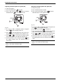
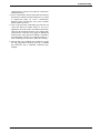
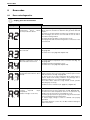
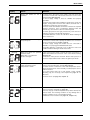
Adjusting minimum power fan speed (P2)
Adjusting maximum power fan speed (P1)
To select fan speed:
To select fan speed:
B Press ON/OFF button
into OFF.
B Press and hold "Program"
button and press
ON/OFF button
to turn appliance ON.
B Press ON/OFF button into OFF.
B Press and hold "Program" button
and press
ON/OFF button to turn appliance ON.
Fig. 25
Fig. 24
B As soon as '188' is displayed, release "Program" button
, and the display reads P2.
B As soon as '188' is displayed, release "Program"
button
, and the display reads P2.
B Press the minus button
B Press
to enter P2 adjustment. The current setting will appear on the display (factory default: 12).
B Press
or
to choose the fan speed suitable
with your installation, see table 18 and table 19.
B Press and hold (± 5 sec.) “Program” button
until
the display flashes, then the selected value is
memorized.
i
22
Proceed directly to Section 6.5 to confirm
CO2 values are within range.
to display P1.
B Press “Program” button
to enter P1 adjustment.
The current setting will appear on the display.
B Press
or
to choose the fan speed suitable
with your installation, see table 18 and table 19.
B Press and hold (± 5 sec.) “Program” button
until
the display flashes, then the selected value is memorized.
i
Proceed directly to Section 6.5 to confirm
CO2 values are within range.
6 720 644 887
Installation instructions
Attention residents of the Commonwealth of Massachusetts:
In the Commonwealth of Massachusetts the following
regulation went into effect on 12/30/2005:
signage installed in accordance with the provisions of
248 CMR 5.08(2)(a)1 through 4.
(a)For all side wall horizontally vented gas fueled
equipment installed in every dwelling, building or
structure used in whole or in part for residential
purposes, including those owned or operated by the
Commonwealth and where the side wall exhaust vent
termination is less than seven (7) feet above finished
grade in the area of the venting, including but not limited
to decks and porches, the following requirements shall
be satisfied:
(b)EXEMPTIONS: The following equipment is exempt
from 248 CMR 5.08(2)(a)1 through 4:
1. INSTALLATION OF CARBON MONOXIDE
DETECTORS. At the time of installation of the side wall
horizontal vented gas fueled equipment, the installing
plumber or gasfitter shall observe that a hard wired
carbon monoxide detector with an alarm and battery
back-up is installed on the floor level where the gas
equipment is to be installed. In addition, the installing
plumber or gasfitter shall observe that a battery
operated or hard wired carbon monoxide detector with
an alarm is installed on each additional level of the
dwelling, building or structure served by the side wall
horizontal vented gas fueled equipment. It shall be the
responsibility of the property owner to secure the
services of qualified licensed professionals for the
installation of hard wired carbon monoxide detectors.
a.In the event that the side wall horizontally vented gas
fueled equipment is installed in a crawl space or an at
tic, the hard wired carbon monoxide detector with alarm
and battery back-up may be installed on the next
adjacent floor level.
b. In the event that the requirements of this subdivision
can not be met at the time of completion of installation,
the owner shall have a period of thirty (30) days to
comply with the above requirements; provided,
however, that during said thirty (30) day period, a
battery operated carbon monoxide detector with an
alarm shall be installed.
2.APPROVED CARBON MONOXIDE DETECTORS.
Each carbon monoxide detector as required in
accordance with the above provisions shall comply with
NFPA 720 and be ANSI/UL 2034 listed and IAS
certified.
3. SIGNAGE. A metal or plastic identification plate shall
be permanently mounted to the exterior of the building
at a minimum height of eight (8) feet above grade
directly in line with the exhaust vent terminal for the
horizontally vented gas fueled heating appliance or
equipment. The sign shall read, in print size no less than
one half (1/2) inch in size, "GAS VENT DIRECTLY
BELOW. KEEP CLEAR OF ALL OBSTRUCTIONS".
1. The equipment listed in Chapter 10 entitled
"Equipment Not Required To Be Vented" in the most
current edition of NFPA 54 as adopted by the Board;
and
2. Product approved side wall horizontally vented gas
fueled equipment installed in a room or structure
separate from the dwelling, building or structure used in
whole or in part for residential purposes.
(c) MANUFACTURERS REQUIREMENTS - GAS
EQUIPMENT VENTING SYSTEM REQUIRED. When
the manufacturer of Product Approved side wall
horizontally mounted gas equipment provides a venting
system design or venting system components with the
equipment, the instructions provided by the
manufacturer for the installation of the equipment and
the venting shall include:
1. Detailed instructions for the installation of the venting
system or the venting system components: and
2. A complete parts list for the venting system design or
venting system.
(d)MANUFACTURER REQUIREMENTS - GAS
EQUIPMENT VENTING SYSTEM NOT PROVIDED.
When the manufacturer of a product approved side wall
horizontally vented gas fueled equipment does not
provide the parts for the venting of flue gases, but
identifies "special venting systems," the following
requirements shall be satisfied by the manufacturer:
1. The referenced "special venting system" instructions
shall be included with the appliance or equipment
installation instructions; and
2. The "special venting systems" shall be product
approved by the Board, and the instructions for that
system shall include a parts list and detailed installation
instructions.
(e) A copy of all installation instructions for all products
approved side wall horizontally vented gas fueled
equipment, all venting instructions, all parts lists for
venting instructions, and/or all venting design
instructions shall remain with the appliance or
equipment at the completion of the installation.
4. INSPECTION. The state or local gas inspector of the
side wall horizontally vented gas fueled equipment shall
not approve the installation unless, upon inspection, the
inspector observes carbon monoxide detectors and
6 720 644 887
23
Installation instructions
3.4
Combustion air requirements
Warning: In areas where outside
temperatures routinely come close to
freezing, sealed combustion operation
is required. Use a concentric
termination or separate terminations for
combustion and vent, which must be
installed on the same wall or roof
surface, however never facing the
direction of prevailing winds. Failure to
do so may result in heat exchanger
freezing up and bursting. This failure is
not covered under the manufacturer's
warranty.
Warning: When installed in an
environment where corrosive chemicals
or dirty air are present, the twin pipe or
concentric vent system is required.
Twin pipe
The tankless water heater is designed as a sealed
combustion appliance. It is recommended that the
combustion air be provided by a dedicated 3" or 4" pipe
from the outside. The combustion air pipe may be PVC
or any other rigid sealed 3" or 4" pipe. The combustion
air piping must pitch down ¼ inch per foot towards
termination to prevent rain water from entering the
appliance. The combustion air inlet, whether terminating
vertically or horizontally, must be located in such a
manner as to provide a minimum 3 foot clearance
from any exhaust vent terminator.
See table 4 for combustion air piping specifications.
Warning: Terminations must prevent
rain and debris from entering the
combustion air and exhaust vent piping.
• Appliances located in unconfined spaces:
– a) An unconfined space is one whose volume is
greater than 50 cubic feet (1.42 cubic meter) per
1000 Btu per hour (292.81 Watts) of the
combined rating of all appliances installed in the
space. That would be 11250 cubic feet (318.6
cubic meters) for the C 1210 ES alone.
– b) In unconfined spaces in buildings of
conventional
frame,
masonry,
or
metal
construction, infiltration air is normally adequate to
provide air for combustion.
• Appliances located in confined spaces:
The confined space must be provided with two permanent openings, one commencing within 12 inches
(304.8mm) of the top and one commencing within
12 inches (304.8mm) of the bottom of the enclosure.
Each opening must have a minimum free area of one
square inch per:
– 1000 Btu/hr (292.81 Watts) if all air is taken from
inside the building
– 2000 Btu/hr (585.62 Watts) if all air is taken from
the outside by horizontal ducts
– 4000 Btu/hr (1171.24 Watts)if all air is taken from
the outside by direct openings or vertical ducts
Or the confined space must be provided with one
permanent opening or duct that is within 12 inches
(304.8mm) of the ceiling of the enclosure. This opening
must have a minimum free area of one square inch per:
– 3000 Btu/hr (878.43 Watts) if all air is taken from
the outside by a direct opening or vertical duct.
Louvers, grills and screens have a blocking effect, when
used, increase the sizes of your openings by 300% for
wood louvers (as wood type will reduce the free air by
75%) and 43% for metal louvers (as metal will reduce
the free air by 30%). Refer to the National Fuel Gas
Code for complete information. In buildings of tight
construction all air should be taken from outside.
Single pipe
Note: This appliance requires 11,250 cubic feet of
available combustion air, or a minimum of 1,406
square feet of space with an 8 foot ceiling to
operate. If the large amount of air space, which
equates to about half of most average sized
homes, is not available, the appliance must pull
air from the outside (see twin pipe above).
Although it is permissible to draw combustion air from
the inside, it is not the manufacturer’s recommended
installation method. Always install a 3 inch 90° elbow on
the top of the combustion air inlet adaptor to prevent
foreign objects from falling into the unit.
If a single pipe installation is utilized, follow guidelines
below for providing adequate combustion air for the
water heater as well as any other appliances that may
consume air in the same space. Always follow local
codes if they are more stringent and regulations.
24
6 720 644 887
Installation instructions
3.5
Proper location for installing your
heater
3.7
Warning: before starting installation:
Carefully select the location of the water heater. For
safety and for proper heater operation, you must provide
combustion air to the heater and a proper exhaust vent
system.
Follow the guidelines below:
B Check that there are no loose or
damaged parts inside the appliance
B Confirm that the gas type of the
heater matches the gas supply you
will be connecting to the heater,
See Fig. 2, page 6.
B 1. Locate the heater where venting, gas and
plumbing connections are feasible and convenient.
B 2. The hot water lines should be kept short and
insulated to save energy. Centrally locating the water
heater is recommended to keep hot water
distribution times even throughout the structure.
Warning: The water in this water
heater is cold and always remains cold
except for the times the burner is on. In
the event of power outage in
conjunction with freezing temperatures,
it is recommended that the heater be
drained.
See chapter 6.2, page 41 “Winterizing”
for draining instructions.
Warning:
Flammable
materials,
gasoline, pressurized containers, or any
other items or articles that are potential
fire hazards must NOT be placed on or
adjacent to the heater. The appliance
area must be kept free of all
combustible materials, gasoline and
other flammable vapors and liquids.
3.6
Mounting installation
i
Front cover should be removed (see
instructions on page 7) in order to inspect
components visually.
Warning: Do not install this appliance
on a carpeted wall. The heater must be
mounted on a wall using appropriate
anchoring materials.
If wall is sheathed with plaster or drywall, it is
recommended that two support boards, either 1"x4" or
½" (minimum) plywood first be attached across a pair of
studs, see Fig. 26, page 26.
B Secure the wall mounting bracket provided with the
heater to a wall surface. The heater must be kept
level on the wall surface, see Fig. 27, page 26.
B Hang the appliance on the bracket, see Fig. 28, page
27.
Heater placement and clearances
The tankless water heater is approved for
installation on a combustible wall (see
chapter 3.7 Mounting installation) provided the
floor
covering
below
the
heater
is
noncombustible.
For installations in an alcove or closet, maintain the
minimum clearances to combustible and noncombustible materials listed below. See also Fig. 7,
page 9.
Studs 16"
(406mm) on
center
Fig. 26 Distance between support boards
6 720 644 887
25
Installation instructions
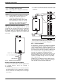
3.8
Gas piping & connections
Before connecting the gas supply, check the rating
plate on the right side of the heater to be sure that the
heater is rated for the same gas to which it will be
connected.
In the United States: The installation must conform with
local codes or, in the absence of local codes, the
National Fuel Gas Code ANSI Z223.1/NFPA 54.
In Canada: The Installation must conform to CGA B149
INSTALLATION CODES and/or local installation
codes.
Warning: DO NOT connect directly to
an unregulated or high pressure
propane line or to a high pressure
commercial natural gas line.
6720608836-10.1AL
Fig. 27 Leveling wall mounting bracket
Warning: The heater must be isolated
from the gas supply piping system
during any pressure testing of that
system at test pressures equal to or
more than 0.5 psig. If overpressure has
occurred, such as through improper
testing of the gas lines or malfunction of
the supply system, the gas valve must
be checked for safe operation.
GAS CONNECTIONS
B Install a manual gas shut off valve on the gas supply
line within easy reach of the appliance.
B Install a union when connecting gas supply.
B The minimum internal diameter required for
any appliance connector is ¾", see Fig. 31 for
more details on pipe sizing.
B Undersized flexible appliance connectors are not
permitted.
6720608158-05.1AL
B National Fuel Gas Code requires that a sediment
trap (drip leg) be installed on gas appliances not so
equipped. The drip leg must be accessible and not
subject to freezing conditions. Install in accordance
with the recommendations of the serving gas
supplier, see Fig. 2.
Fig. 28 Mounting the heater
Warning: Appliance must be installed
vertically.
26
6 720 644 887
Installation instructions
Minimum
3”
Gas supply
Cap
Inlet gas particle
screen (included)
Fig. 29 Gas connection
Once connections are made, check for gas leaks at all
joints. Apply some gas leak detection solution to all gas
fittings. Bubbles are a sign of a leak. A combustible gas
detector may also be used to detect for leaks.
Gas piping
Fig. 30
Danger: If you have a leak, shut off the
gas. Tighten appropriate fittings to stop
leak. Turn the gas on and check again
with a gas leak detection solution.
Never test for gas leaks using a match
or flame.
GAS LINE SIZING
The gas supply piping for a single heater should be
sized for a maximum draw of 225,000 BTUH. Measure
the length of gas supply line from the building's gas
main to the heater and use the tables in Fig. 31, page
28 or the gas line manufacturer’s sizing tables to
determine the pipe diameter necessary. If there are
more gas appliances on the line, size the gas line
according to the total maximum amount of BTU input
rating of all appliances combined.
Note: Undersizing the gas line may result in diminished
hot water flow rate and temperature. See chapter 3.14,
page 35 for the procedure to measure gas pressure.
Proper gas pressure must be confirmed at time of
installation.
6 720 644 887
27
Installation instructions
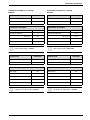
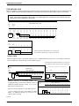
FOR NATURAL GAS
Maximum Capacity of pipe in Cubic Feet of Gas per Hour for Gas Pressure of 0.5 Psig or less and a Pressure drop
of 0.3” in Water Column (0.75mbar).(Based on a 0.60 Specific Gravity Gas) Btu numbers given in thousands.
Follow boxed numbers for piping just one C 1210 ES/ESC (example: ¾” B.I. Natural Gas pipe for 10 ft
(3.0m). will handle 278,000 btu’s (81.5 kWh). For multiple appliances combine the total maximum btu input
load and then refer to applicable chart below.
Nominal
Length of Black iron Pipe , Feet
Iron
Pipe
Internal
Size,
Diameter
inches
inches
10
20
30
40
50
60
70
80
90
100
125
150
175
200
1/4
0.364
32
22
18
15
14
12
11
11
10
9
8
8
7
6
3/8
0.493
72
49
40
34
30
27
25
23
22
21
18
17
15
14
1/2
0.622
132
92
73
63
56
50
46
43
40
38
34
31
28
26
3/4
0.824
278
190
152
130
115
105
96
90
84
79
72
64
59
55
1
1.049
520
350
285
245
215
195
180
170
160
150
130
120
110
100
1 1/4
1.380
1050
730
590
500
440
400
370
350
320
305
275
250
225
210
1 1/2
1.610
1600
1100
890
760
670
610
560
530
490
460
410
380
350
320
2
2.067
3050
2100
1270 1150 1050
990
930
870
780
710
650
610
1650 1450
Length of Flexible Corrugated Stainless Steel Tubing (CSST), Feet
Tube
size,
inches
1/2
EHD*
10
20
30
40
50
60
18 EHD 82
58
47
41
37
34
3/4
23 EHD 161
116
96
83
75
68
1
30 EHD 330
231
188
162
144
131
1 1/4
37 EHD 639
456
374
325
292
267
* EHD = Equivalent Hydraulic Diameter. The greater the
value of EHD, the greater the gas capacity of the tubing.
FOR LP GAS
Maximum Capacity of Pipe in Thousands of BTU per Hour of Undiluted Petroleum Gases (at 11 inches Water Column Inlet
Pressure) (Based on a Pressure Drop of 0.5 Inch Water Column).
* EHD = Equivalent Hydraulic Diameter. The greater the
value of EHD, the greater the gas capacity of the tubing.
Length of Flexible Corrugated Stainless Steel Tubing (CSST), Feet
Nominal
Tube
size
inches
Black Iron Pipe
iron
Length of Pipe, Feet
pipe
Inches
1/2
3/4
1
Maximum
10
20
30
40
50
60
80
100
125
150
200
291
200
160
137
122
110
94
84
74
67
58
418
336
287
255
231
197
175
155
140
120
1145 787
608
632
541
480
434
372
330
292
265
227
Capacity
of
Semi-Rigid
(flexible,
EHD*
10
Undiluted Liquefied Petroleum Gases (at 11 inches
Water Column Inlet Pressure).
(Based on a Pressure Drop of 0.5 Inch Water Column)
* Source National Fuel Gas Code NFPA 54, ANSI
Z223.1 - No Additional Allowance is necessary for an
ordinary number of fittings
30
40
50
60
1/2
18 EHD 129
91
74
64
58
53
3/4
23 EHD 254
183
151
131
118
107
1
30 EHD 521
365
297
256
227
207
1 1/4
37 EHD 971
661
528
449
397
359
non
corrugated) Tubing in Thousands of BTU per Hour of
20
Copper
Length of Tubing, Feet
Outside
diameter
Inch
10
20
30
40
50
60
70
80
3/8
39
26
21
19
_
_
_
_
90 100
_
_
1/2
92
62
50
41
37
35
31
29
27
26
5/8
199 131
107
90
79
72
67
62
59
55
3/4
329 216
181 145
131
121 112 104
95
90
Fig. 31
28
6 720 644 887
Installation instructions
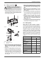
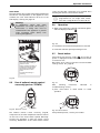
3.9
Water connections
Warning: This heater is not approved
for preheated water supply exceeding
140°F (60°C).
B When facing the heater, the ¾" cold connection is
on the bottom right and the hot connection is on the
bottom left. Centrally locating the water heater is
recommended to keep hot water distribution times
even throughout the structure.
B Never sweat any piping directly to or beneath
the water connections, as damage will occur to
the internal water valve from heating of the
pipe.
B Keep water inlet and outlet pipes to no less
than ¾" (19.05mm) diameter to allow the full
flow capacity.
B If the cold and hot connections to the heater are
reversed, the heater will not function. Be certain there
are no loose particles or dirt in the piping. Blow out
or flush the lines before connecting to the water
heater.
B Full port shutoff or isolation valves must be
installed on both the cold water supply and hot
water outlet lines to facilitate servicing the
heater (see Fig. 34).
B For installation on a private well system with the use
of a pressure tank, the lowest pressure range setting
recommended is 40-60 psi (2.75 - 4.15bar).
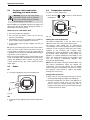
3.10 Water quality
HOT
COLD
Fig. 32
1
2
Water quality can have an impact on appliance
longevity and may void the manufacturer's warranty.
For water analysis data call your local water department,
or if on a well, have well water analyzed periodically. If
water quality exceeds one or more of the values
specified below, Bosch recommends installing a water
conditioner or softener. If the tankless water heater is
operating in applications where the outlet temperature
exceeds 140°F, a water softening system is strongly
recommended. The higher the set temperature is on the
appliance, the greater the risk for scale/mineral
deposits. Damage from scale/mineral deposits is not
covered under warranty. Refer to manufacturer’s limited
warranty.
Description
pH
6.5 - 8.5
TDS (total Dissolved
Solids)
mg/l or ppm
500
Total hardness
mg/l or ppm
100
(6 grains)
Aluminum
mg/l or ppm
2.0
Chlorides
mg/l or ppm
250
Copper
mg/l or ppm
1.0
Iron
mg/l or ppm
0.3
Manganese
mg/l or ppm
0.05
Zinc
mg/l or ppm
5.0
pH
6720608836-11.1AL
Fig. 33 Water filter
1
2
Water valve with engine
Water filter
B The use of unions when connecting both water
pipes to the inlet and outlet connections is
required. This will facilitate any necessary
servicing.
B Plastic or PEX type plumbing line materials are not
suitable for connecting directly to the water heater.
B Although water piping throughout the building may
be other than copper, we recommend that copper or
suitably rated stainless steel flex line piping be used
for the water connections for at least 1.5 feet on
either side of the water heater (follow local codes if
more stringent).
6 720 644 887
Max. Levels
Table 20
29
Installation instructions
Connecting the pressure relief valve (PRV)
The listed pressure relief valve must be installed at the
time of installation. No valve is to be placed between
the PRV and the heater. No reducing coupling or
other restriction may be installed in the discharge line.
The discharge line must be a minimum of 4" above a
drain and installed such that it allows complete drainage
of both the PRV and the line. The discharge line must be
placed where it will not cause any damage.
The location of the PRV must be readily accessible for
servicing or replacement, and be mounted as close to
the water heater as possible. See Fig. 34. To install the
PRV, a suitable fitting connected to an extension on a
“T” fitting can be sweated to the hot water line.
Support all piping.
Pressure
relief
valve
Fig. 34 Plumbing Connections (with isolation valves)
and Pressure Relief Valve
Warning:
In applications where inlet water
temperature can exceed 140°F (60ºC), a
thermostatic or mixing valve must be
installed before the appliance to prevent
water exceeding 140°F (60°C) from
entering the appliance.
30
6 720 644 887
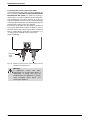
Installation instructions
3.11 Filling the condensate trap
The condensate trap can be filled before or after
connecting the vent pipe.
B Fill the condensate trap by pouring approximately 14
oz. (400ml) of water into the top of the drain tube. To
avoid damage to the appliance use a funnel in this
operation, see Fig. 37, page 31.
Filling the condensate trap before vent pipe
installation
Danger: Prior to initial start up, and
after appliance has been out of use for a
long time or after cleaning the siphon,
the condensate trap must be filled with
water. This is to prevent dangerous
exhaust gases from entering the
building.
B Fill the condensate trap by pouring approx.14 oz.
(400ml) of water into the exhaust accessory on the
top of the appliance, see Fig. 35.
Fig. 37 Filling the condensate trap after installation
B Loosen the three screws of the control unit.
Fig. 35 Filling the condensate trap at start up
Filling the condensate trap after vent pipe
installation
After appliance has been out of use for a long time or
after cleaning siphon, refill the condensate trap with
water.
Please proceed as follows:
Fig. 38
B Put the control unit in service position by engaging its
tabs with the holes in the bottom horizontal sheet
metal, see Fig. 39.
B Check water level in the condensate trap.
B Remove front cover, see Fig. 4, page 7.
B Open the four clips and remove the combustion
cover, see Fig. 5, page 7.
B Remove the clip and disconnect the drain tube, see
Fig. 36.
Fig. 39 Water level in condensate trap
B After filling, reassemble all parts in reverse order.
Fig. 36 Disconnect drain tube
6 720 644 887
31
Installation instructions
3.12 Domestic hot water recirculation
Although recirculation directly through the tankless
water heater is allowed, temperature stability is
improved by recirculating through a mini-tank as shown
in Fig. 35. By using the design in Fig. 35, there is no
recirculation of hot water through the tankless water
heater and therefore, does not affect the heat
exchanger warranty of 15 years. Direct recirculation
through the tankless water heater is permissible,
however, the heat exchanger warranty is reduced to 3
years; contact Bosch Thermotechnology for further
installation requirements. The following drawing is
provided to outline one possible recirculation design
using the water heater in conjunction with an Ariston
mini tank water heater. This schematic is for illustration
only and must not be used for actual Installation without
appropriate engineering and technical advice from a
properly licensed professional in the locality where the
installation is made.
GWH
C 1210
ES/
ESC
5
2
1
4
3
6720608836-12.1AL
Ariston Minitank
Fig. 40 Recirculation application
1
2
3
4
5
Full port isolation valve
Circulator on timer or aquastat
Check valve
PRV
Expansion tank
The use of a small electric mini-tank water heater (4-6
gallon size) should be used for this application and
designed so the circulator will circulate the water
through the mini-tank and the building's hot water return
loop only. Timed or thermostatically controlled
operation of the pump is commonly done. Contact
Bosch Water Heating if further information is needed.
32
6 720 644 887
Installation instructions
3.13 Space heating applications
Warning: Ensure the primary pump is
properly sized to provide adequate flow
for the system heat load.
Warning: If the set point temperature is
above 120°F, precautions should be
taken to protect users of potable water
from scalding.
For Pump sizing please refer to the
pressure drop curves, Fig. 41. Also
remember to account for system piping
pressure loss. A minimum of 1.7 GPM is
recommended to provide adequate flow
through the water heater when
determining the size of the primary pump.
i
Warning: Propylene glycol may be
used for freeze prevention ONLY on the
space heating side of the heat
exchanger. Do not use ethylene glycol
(automotive antifreeze).
Warning: The use of a flow switch is
recommended to ensure DHW priority
and to prevent “cold-blow” situations
when the Bosch tankless water heater is
used with an air-handling system. The
flow switch should be used to disable
the blower on the air-handling system
when domestic water is used.
Bosch tankless water heaters are approved for use in
combination DHW and space heating applications
(open-loop setup). These water heaters are not
approved for use in space heating only applications
(closed-loop setup). Bosch supports applications of
combination DHW and space heating in an open loop
configuration if plumbed similar to Fig. 42. Use of a
Bosch tankless water heater in a combination DHW
and space heating application will result in the product
warranty being reduced to 3 years.
C1210ES\ESC
70
60
Pressure (Feet of Head)
50
40
30
20
10
0
0.0
1.0
2.0
3.0
Flow (GPM)
4.0
5.0
6720644887-01.1V
Fig. 41 Pressure drop curve
6 720 644 887
33
Installation instructions
8
18
13
17
T
5
7
12
22
16 15
2
1
11
21
14
9
5
20
9
10
3
6
9
5
4
6720644887-02.1V
19
Fig. 42 Space heating diagram
1
2
3
4
5
6
7
8
9
10
11
12
13
14
15
16
17
18
19
20
21
22
34
Hot water outlet
Cold water inlet
Pressure relief valve
Gas supply
Shut off gas valve
Thermal expansion tank (as required)
Atmospheric vacuum breaker
Cold inlet
Check valve
Pump
Thermostatic mixing valve
Thermometer (optional)
DHW outlet
Water to water heat exchanger
Backflow preventer
Automatic water feed
Thermostat
Space heating zone
Zone controller
Space heating pump
Expansion tank
Pressure relief valve
6 720 644 887
Installation instructions
3.14 Measuring gas pressure
Gas pressure must be measured upon installation.
Connecting manometer
B Shut off gas supply at installer supplied shutoff valve
for this water heater.
B Remove front cover and locate inlet gas pressure test
port (see Fig. 44).
B Loosen screw inside left test point fitting (do not
remove) and connect manometer tube to test point.
possible error code faults and must be corrected. See
Gas Connections, chapter 3.8, page 26.
P1 fan speed:
Factory default: NG: 52, LP: 53
Lowering P1 fan speed reduces the maximum BTU
input.
As a temporary measure if the gas pressure in P1 is
below specification, lower P1 fan speed incrementally
until minimum inlet gas pressure reaches specified
range (table 21). After raising gas pressure, reset
appliance to P1 factory default setting (NG: 52, LP: 53).
Static Pressure Test
B Turn gas supply back on.
B Record static gas pressure reading in table 22.
Operating Pressure Test
B Press ON/OFF button
to turn off the appliance.
B Press and hold "Program"
button and press
ON/OFF button
to turn appliance ON.
Fig. 44 Gas pressure test port (left tapping)
Static Gas Pressure Reading (see Chapter 3.14)
enter here: ___________________ Date: ___________
Operating Gas Pressure Reading (see Chapter 3.14)
Fig. 43
B As soon as '188' is displayed, release "Program"
button
, and the display reads P2.
B Press
or
enter here: ___________________ Date: ___________
Table 22
until P1 appears.
Note: While in this mode the appliance will run
constantly at maximum power and allow
maximum water flow.
Gas type
NG
LPG
minimum pressure
3.5" WC
8" WC
Table 21Minimum inlet gas pressure under full operation
B Operate all other gas appliances (except heater) on
same gas piping system at maximum output.
B Turn on high volume of hot water flow (at least 6
gpm) and burner will light. If heater display reverts to
P2, open more hot water fixtures to allow sufficient
flow. Press
until P1 reappears on the display.
B Record lowest operating gas pressure reading in
table 22.
Gas pressures lower than 3.5" W.C. for Natural Gas or
8" W.C. for LPG will result in insufficient degree rise to
the hot water being used, reduced hot water volume,
6 720 644 887
35
Electrical connections
4
Electrical connections
4.1
Electrical power supply
4.2
Warning:
For
safety
reasons,
disconnect the power supply cord to
the heater before any service or testing
is performed.
Warning: This heater must be
electrically grounded in accordance
with the most recent edition of the
National Electrical Code. NFPA 70. In
Canada, all electrical wiring to the
heater must be in accordance with local
codes and the Canadian Electrical
Code, CSA C22.1 Part 1. Do not rely
on the gas or water piping to ground the
metal parts of the heater.
The tankless water heater requires an electrical power
supply from a 120VAC / 60Hz properly rated
receptacle and must be properly grounded.
A means for switching off the 120VAC power supply
must be provided.
The heater is wired as shown in the wiring diagram
(chapter 9, Fig. 72).
Position of the fuses in control unit
To check fuses, proceed as follows:
B Unplug the water heater's power cord.
B Remove the front cover, see Fig. 4, page 7.
B Remove the three screws from the control unit.
Fig. 46
B Remove the six screws from the back cover of the
control unit, see Fig. 47, pos. 2.
B Check the fuses on the printed circuit board, see Fig.
47, pos. 3.
1
6720608643-15.1AL
1
2
Fig. 45 Connecting power supply cord
1
Power cord length: 3ft.
3
Note: Outlet appliance is plugged in to should be
clear from possible water damage.
6720608158-78.1AL
Fig. 47 Fuses position
B After checking the fuses, reinstall all parts in reverse
order.
36
6 720 644 887
Operation instructions
5
Operation instructions
Fig. 48
1
2
3
4
5
6
7
5.1
On/Off button
Reset button
Program button
LCD display
Up button
Down button
Power On or stand-by LED
Description of LCD Display
Warning: Do not use any cleaning
agressive or corrosive agents to clean
the window.
Fig. 52 Locked condition indicator (only with remote
control)
Fig. 53 Flame indicator
Fig. 49 Power bar indicator (input)
Fig. 50 Temperature indicator
Fig. 51 Error indicator
6 720 644 887
Fig. 54 Solar mode indicator (see chapter 5.4,
page 38)
Fig. 55 Remote control indicator
37
Operation instructions
5.2
For your safety read before
operating your water heater
Warning: If you do not follow these
instructions exactly, a fire or explosion
may result causing property damage,
personal injury or loss of life.
5.4
Temperature selection
To select hot water temperature:
B Press buttons
temperature.
or
in order to reach desired
A. This appliance is equipped with electronic ignition for
lighting the main burner. When turning the heater on,
follow these instructions exactly.
WHAT TO DO IF YOU SMELL GAS
B Do not try to light any appliance.
B Do not touch any electric switch; do not use any
phone in your building.
Fig. 57
B Immediately call your gas supplier from a neighbors
phone. Follow the gas supplier’s instructions.
Setting the water temperature
B If you cannot reach your gas supplier, call the fire
department.
B. Use only your hand to press the on/off control switch.
Never use tools. Follow these instructions exactly. If
control switch is jammed, close the gas supply and call
a qualified service technician. Attempted forceful repair
may result in a fire or explosion.
C. Do not use this appliance if any part has been under
water. Immediately call a qualified service technician to
inspect the appliance and to replace any part of the
control system and any gas control which has been
under water.
5.3
Power
On
B To start the appliance press the On/Off button.
The desired temperature of the hot water can be
adjusted on the front control panel of the heater.
The tankless water heater has an electronically
controlled gas valve that modulates the burner input in
response to both varying hot water flow rates and/or
changes in any incoming and outgoing water
temperatures. Set the temperature on the appliance to
the desired outlet temperature. Avoid setting the
appliance to a higher temperature and mixing in cold
water. This causes unnecessary gas consumption and
risks the formation scale/mineral deposits. See
Section 3.10 Water Quality.
Note: The water heater, running at minimum BTU, may
still achieve temperatures above the desired set
temperature. Low flow rate fixtures are the leading
cause of this type of temperature overshoot. To combat
this symptom, clean fixtures or replace with higher
flowing ones if necessary.
Saving water resources:
B Make sure you close all the taps after any use. Avoid
leaving the taps dripping. Repair any leaking tap.
B Define the temperature you want, in the appliance or
with the remote control. This way you have the
precise water flow needed (mixing cold water to
regulate temperature will increase the water flow with
consequent waste of water)
Fig. 56
Off
B To shut down the appliance press the On/Off button
again.
38
6 720 644 887
Operation instructions
Solar mode
The water heater will not ignite if inlet water temperature
exceeds the set temperature on the appliance. In this
condition, the solar mode indicator will show on the
LCD display. See Fig. 54, page 37.
Warning:
In applications where inlet water
temperature can exceed 140°F (60ºC), a
thermostatic or mixing valve must be
installed before the appliance to prevent
water exceeding 140°F (60°C) from
entering the appliance.
control unit (Fig. 84, component 16) is required when
installing the remote control with this heater.
i
5.6
NOTE: up to 6 remote controls can be
programmed for one single water heater,
each with a range distance of 98 ft. (30 m).
Operation
B When a hot water tap is opened, main burner ignites
and LCD displays indication
.
DANGER
Fig. 60
B LCD flashes until selected temperature is reached.
B Power bar indicates power percentage in use.
HOT
5.7
BURN
Water temperature over 125°F can
cause severe burns instantly or
death from scalds.
Reset button
If the LCD shows the error symbol
do not shut off
power or unplug the heater. Follow instructions below
to reset error first.
Record the error code on LCD and consult “Problem
solving” section 8.1, page 50.
Children, disabled and elderly are
at highest risk of being scalded.
See instruction manual before
setting temperature at water
heater.
Feel water before bathing or
showering.
Fig. 58
5.5
Use of optional remote control
accessory (part no. TSTAT2)
Fig. 61
After
following
instructions
“Troubleshooting” section,
indicated
in
B press reset button to return heater to normal
operation.
Fig. 59 Remote control
Fig. 62 Reset button
The wireless remote control accessory (Fig. 84,
component 13) and the temperature selector buttons
on the front of the water heater operate identically.
Contact your distributor to order the remote control
accessory. Modification of the water heaters interior
If the problem persists, contact your installer.
6 720 644 887
39
Maintenance and service
5.8
6
Program button
Maintenance and service
Warning: Always shut off the electrical
power supply, shut off the manual gas
valve and shut off the water valves when
servicing.
Caution:
B Check and clean the complete water
heating system once a year.
Fig. 63 “Program” key
5.8.1
B Carry out maintenance if necessary.
Immediately repair defects to avoid
damage to the system.
Memorizing selected temperature
B Press buttons
temperature.
or
to select desired
B Hold “Program” button for 3 seconds to save
temperature.
When LCD stops blinking, temperature is saved in
memory.
Annual maintenance table
1.
Inspect venting system
2.
Inspect heat exchanger
Using “Program” function
In order to select memorized temperature
3.
Inspect burner
B Press “Program” key.
4.
Inspect condensate trap
LCD shows pre-memorized temperature, which is now
the hot water selected temperature.
5.
Inspect water filter
5.9
Locked condition
This condition is only valid for appliances with one or
more remote controls installed.
Table 23 Annual maintenance
6.1
Annual maintenance
(To remove front cover, see page 7.)
Venting System
Fig. 64 Locked condition
Whenever LCD shows
the temperature setting
cannot be adjusted because the appliance is in use by
another user who has already selected a different
temperature. Appliance will be automatically unlock 5
minutes after closing hot water tap.
• Venting system - inspect inside of flue pipe for any
blockage or restriction. Observe burner flames
during heater operation. (front cover must be
removed). Inspect the combustion air inlet pipe for
blockage or debris. Inspect combustion air and
exhaust terminations for blockage or debris.
Combustion Chamber
• Inspect burner observation window (Fig. 77, #14) for
cracks or spillage of flue gases. Observe burner
flames during heater operation. Flames should be
steady and blue with no signs of yellowing. Yellow
burner flames are an indication of improper
combustion. Refer to Section 3.4, page 24 & & 3.3,
page 10 of this manual to verify exhaust system and
combustion air supply meets manufacturer's
specifications.
Pressure Relief
• Manually open the pressure relief valve to ensure
proper operation.
40
6 720 644 887
Maintenance and service
water heater to catch residual water remaining inside
the water heater.
Inlet Water Filter
• Verify the inlet filter screen is clean and undamaged.
The inlet water filter is located between the ¾" cold
water inlet fitting on the right side of the appliance,
and the water valve (See Fig. 33, page 29). Close
installer supplied water shutoff, carefully lift the water
valve, then rotate back. Remove filter, clean and or
replace if damaged.
Descaling
• In areas where the water supply has a high mineral
content, the heat exchanger should be flushed with a
descaling solution. Scale build up will shorten the life
of the water heater and damage resulting from scale
is not covered under warranty. Refer to section 6.3
for detailed instructions on descaling the heat
exchanger.
Fin Coils
• Inspect heat exchanger fin coil for soot build-up or
blockage. To access fin coil, consult service bulletin
at www.bosch-climate.us. If there is evidence of soot
build-up or blockage, the heat exchanger should be
removed by a professsional and cleaned thoroughly.
Condensate trap
• Check water level in the condensate trap,
see Fig. 35.
• If appliance is out of service for more than 10 days,
fill as described on page 31.
6. Using an air compressor, blow short bursts of air
(100psi max) through the outlet water connection
until there is no water present coming through the
inlet water connection of the heater.
7. Reconnect water fittings and return heater to service
when danger of freezing has passed.
6.3
Periodic descaling may be necessary in areas with high
mineral content in the water or if the heater is operating
in applications where the outlet temperature exceeds
140°F. Scale buildup in the heat exchanger may result
in lower flow rates, error codes of A7 and E9 and boiling
sounds in the heat exchanger.
A water softener is required if the water hardness
exceeds 6 grains/gal (103 mg/l) calcium carbonate.
Damage to the water heater resulting from hard water or
scale deposits will not be covered under warranty. See
Section 3.10 Water Quality.
Descaling using a pump
1.
Disconnect electrical supply from the water heater.
2.
Shut off the water supply to the water heater using
(installer supplied) shutoff valve.
3.
Open hot water taps to drain and relieve pressure
from the plumbing system.
4.
Drain water from the unit's heat exchanger by
disconnecting inlet and outlet water connections
from the heater.
5.
Connect a line (A) from the outlet of the circulating
pump (installer supplied) to the inlet water fitting on
the water heater (see Fig. 65.)
6.
Using another line (B), connect to the water outlet
fitting on the water heater. Route the other end of
this line into a descaling reservoir.
7.
Using a 3rd line (C) from the descaling reservoir,
connect to the inlet side of circulating pump. Install
a filter on the end of the line in the descaling
reservoir.
8.
Make sure all connections are "water tight.".
9.
Fill tank with descaling solution so both lines inside
are submersed. We recommend a straight white
vinegar solution. If using a commercial descalant,
refer to manufacturer's instructions for proper
dilution ratio.
• Check for debris and clean if needed.
6.2
Winterizing for seasonal use
The water heater must not be installed in a location
where it may be exposed to freezing temperatures. If the
heater must be left in a space which is likely to
experience freezing temperatures, all water must be
drained from the heater. Freeze damage is not covered
under the warranty. NOTE: Use of agents such as antifreeze is not permitted and voids the warranty, as they
may cause damage to the water heater's internal
components.
1. Press ON/OFF switch on the water heater to turn
OFF the heater and unplug power supply cord. The
display should be blank.
2. Shut off gas supply to heater.
3. Shut off the cold water supply to the water heater
using installer supplied shutoff valve.
4. Open hot water taps to drain and relieve pressure
from the plumbing system. If water continues to flow
after 5 minutes, a crossover of the hot and cold water
pipes is present and must be corrected before
proceeding.
5. Disconnect inlet and outlet water pipes from the
water heater. Place a small bucket underneath the
6 720 644 887
Mineral scale build-up
10. Operate the circulating pump.
11. Make sure there are no leaks and the solution is
flowing from the descaling reservoir through the
heater and returning to the reservoir.
12. Run solution through the heater until the solution
returning to the descaling reservoir comes out
clear. (Changing to a fresh solution may be
necessary during this process).
41
Maintenance and service
13. Disconnect all lines and drain all solution from heat
exchanger. Properly discard of solution.
B Remove the condensing heat exchanger unit from
the appliance by pulling it towards you.
14. Position a container below the hot water outlet and
connect cold water supply. Open cold water
supply shutoff valve and flush heat exchanger with
clean water.
B Dismantle all parts for inspection and cleaning.
15. Shut cold water shutoff valve and reconnect hot
water supply to the water heater.
16. Reconnect electrical supply to unit, open water
shutoff valves, and return the unit to service.
6720608836-03.1AL
Fig. 67 Condensing heat exchanger
B Check the condensing heat exchanger for any
obstruction.
Fig. 65
6.4
B Flush the condensing heat exchanger unit with water.
Condensing heat exchanger unit
The condensing heat exchanger unit must be checked
once a year by a qualified and trained technician. If
repairs are needed, the repairs should be done by a certified Bosch technician.
B Check all gasket and o-rings for damage and replace
if necessary.
i
It is important to inspect and properly
replace the gaskets and o-rings.
B Assemble the condensate unit and all other parts in
reverse order of disassembly.
6.5
Adjusting CO2
The CO2 can only be adjusted by a certified gas
technician with a calibrated CO2 analyzer.
i
6720608836-01.1AL
Fig. 66 Condensing heat exchanger unit
Condensing heat exchanger unit maintenance:
B Shut off power. Disconnect power cord.
B Dismantle all inlet, outlet pipes and the condensate
tube from the condensing heat exchanger unit.
42
CO2 adjustment is required in Natural
Gas installations where energy content
is less than 900 BTU/cuft, and in
installations with repeated unresolved
EA and EC errors (ref. to page 50
“Problem solving”).
Caution: One factor that may affect
CO2 levels is insufficient gas pressure.
Please see Chapter 3.14 for the
procedure to measure gas pressure
and record your findings below:
Static Gas Pressure:
“ WC
6 720 644 887
Maintenance and service
P1 Operating Pressure:
“ WC
The P1 minimum operating gas pressure is 3.5" WC for
Natural Gas and 8" WC for Propane. Do not proceed in
adjusting CO2 until pressure is at or above these levels,
but not to exceed 10.5" WC for Natural Gas and 13"
WC for Propane.
B Record the CO2 reading in P2 below.
P1 CO2 Reading:
% CO2
P2 CO2 Reading:
% CO2
Note: When making adjustments,
combustion cover is installed.
A. Once Gas Pressure is adequate
CO2 range (%)
B Press ON/OFF button to turn OFF the heater.
B Remove brass flat head screw on the exhaust collar
as seen in Fig. 68.
B Insert CO2 analyzer probe into the measuring port.
The tip of the probe should be in the center of the flue
pipe (approx 1.5" inserted). Avoid air gaps between
probe and measuring port as they can alter readings.
make
sure
Max. CO level
(measured)
Nat. Gas
max. input
P1
8.3 % - 8.9%
< 290 ppm
min. input
P2
2.1 % - 2.4 %
< 60 ppm
LP Gas
max. input
P1
9.9 % - 10.5 %
< 290 ppm
min. input
P2
2.5 % - 2.8 %
< 60 ppm
* Values above are for climate controlled conditions.
Inputs such as gas pressure, heating value of the gas,
humidity and temperature of combustion air all impact CO
and CO2 values. Changes in these inputs can result in
different CO and CO2 values on the same appliance.
Table 24 CO2 & CO target numbers
C. Adjusting CO2:
Note: P1 adjustment will change the P2 reading.
Confirm the P1 value BEFORE adjusting the P2
level.
Fig. 68 Measuring port
B While holding the Program (P) button, press the ON/
OFF button to turn ON the heater (see Fig. 69).
When ‘188’ flashes on the display, release the
Program button. The display should now read P2.
Press
button until “P1” appears on display.
1. If P1 CO2 level is incorrect:
B Loosen yellow painted Phillips screw (1) and cover
should rotate down (2) revealing a recessed brass
slotted screw. Fig. 70.
B Turning the slotted screw counter clockwise will
raise P1 CO2 levels and clockwise will lower P1
CO2 levels. Adjustments to the slotted screw will
also change P2 CO2 levels.
B After bringing the P1 CO2 readings into proper
range, press the
button to enter the P2 mode.
Measure CO2 readings in P2 mode.
2. If P2 CO2 level is incorrect:
Fig. 69
B Remove yellow painted #40 Torx cover from the front
of the gas valve. (Fig. 71) A plastic #40 Torx screw
will be revealed.
B. Measuring CO2 (Combustion cover must be
installed):
B Turning the plastic #40 Torx screw counterclockwise will lower P2 CO2 levels and clockwise
will raise P2 CO2 levels.
B Open all hot water taps to achieve a flow rate of at
least 6 gallons per minute. (1 tub and 2 sinks should
be sufficient). If heater display reverts back to P2,
open more hot water fixtures to allow sufficient flow.
Press
until P1 reappears on the display.
Note: This screw adjustment is very sensitive and
should be made in small increments. It may take several
minutes for readings to stabilize.
B Record the CO2 reading in P1 below. (Analyzer
reading may take several minutes to stabilize).
B Press the
button until P2 appears. Unit will ramp
down to low fire and the water flow should decrease.
6 720 644 887
3. Verify that both P1 and P2 CO2 readings are within
the ranges specified in table 24. Repeat steps 1 and 2
as necesssary until CO2 values are within the specified
ranges.
43
Maintenance and service
Final Readings
P1 CO2 Reading:
% CO2
P2 CO2 Reading:
% CO2
D. Returning to Service:
1. Return slotted screw cover to original position.
2. Reinstall Torx cover.
3. Remove CO2 analyzer probe and reinstall flathead
screw with gasket in exhaust collar.
4. Press ON/OFF button to turn OFF the heater and
then turn ON the heater.
5. Heater is ready for normal operation.
1
3
2
6720608836-04.1AL
Fig. 70 Adjusting P1 CO2 level
6720608836-05.1AL
Fig. 71 Adjusting P2 CO2 level
44
6 720 644 887
Maintenance and service
6.6
Program values
This section describes details on programming the
appliance. For most applications the factory default values will provide robust and stable operation. Only
adjust the factory settings if the installation requires
changes as indicated in the appropriate section of this
manual.
Program Description
P0
Factory Default
Temperature range H: C 1210 ES
settings
Refer to chapter 6.7 Control board diagnostics (page
35) regarding how to access these P-modes.
Caution: Misadjusted program
values can lead to appliance
malfunction, errors, and service
calls.
MIN
MAX
Comment
_
_
This values are set from factory
they cannot be changed.
C: C 1210 ESC
P1
Maximum Fan
Speed Power
NG:52, LP:53
21
NG:52, LP:53
see chapter 3.14, page 35
note: reducing P1 values below
maximum will reduce maximum
power of the appliance.
P2
Minimum Fan
Speed Power
12
12
20
see chapter 3.3.7, page 20
P3
Remote Control
Registration
_0
_0
6
see chapter 5.5, page 39
P4
Access to
Diagnostic Mode
E
0d
10F
see chapter 6.7, page 46
P5
Cascade Mode
NO
NO
CC
contact Bosch
Thermotechnology for details
P6
Temperature Unit
°F
°F
°C
P8
Back light
dE
dE
ON
P9
Fan Purge
PH
Cascading type
IC
IC
SC
PC
Master/Slave
mode
CS
CS
CM
Table 25
dE turns back light off after 60
seconds from last button
pushed, ON turns backlight on
permanently
runs primary and secondary
fans when P9 is selected by
depressing the “P” - button
This menu is only available
when cascade mode is selected
CC.
Contact Bosch Water Heating
for details.
Program values, factory default settings and ranges.
6 720 644 887
45
Maintenance and service
6.7
Diagnostic menu
1. Press ON/OFF button to turn off the appliance.
2. Press and hold "Program"
button and press
ON/OFF button to turn appliance ON.
3. Release the
button when '188' appears on the
display. The display should read 'P2' when the
program button is released. If not, repeat process.
4. Press and release the
button on the control
panel until the display reads 'P4'. You are now in the
diagnostic mode of the control board.
5. When the display reads 'P4', press and release the
button once again and the display should read
'E'.
6. Use the
and
buttons on the control unit to
cycle through different diagnostic modes available.
7. Once in the selected diagnostic mode of your
choice, press and release the
button to display
the diagnostic information.
B EXAMPLE: to read the flow rate in gallons per minute
while the unit is flowing water, cycle to the '3d' mode
and press the
button. A reading of 25 on the
display would indicate the heater is reading a flow
rate of 2.5 gallons/minute.
B Once the information is obtained, press the
button again to return to the diagnostic mode menu
and scroll to addition diagnostic information.
8. Press ON/OFF button to turn OFF the appliance and
back ON again to return heater to normal function.
Diagnostic menu
7F
7th most recent error
8F
8th most recent error
9F
9th most recent error
10F
10th most recent error
H0
Numbers of hours - mode 0
H1
Numbers of hours - mode 1
H2
Numbers of hours - mode 2
Table 26
6.7.1
Working hours
To see how many hours the appliance has worked,
please enter the “Diagnostic menu” (chapter 6.7);
B Select the sub-mode “H0”.
Write the number that shows in the display.
B Select the sub-mode “H1”.
Write the number that shows in the display.
B Select the sub-mode “H2”.
Write the number that shows in the display.
After checking the sub-modes H0, H1 and H2, introduce the values in the table below;
Working hours
Number in H0
______
_______ +
Number in H1
______ (X 100) =
_______ +
Number in H2
______ (X 10 000) =
_______ +
(H0 + H1 + H2) = Total of hours
_________
Table 27
Example:
E
Entry/Exit into sub-modes
0d
Set-point temperature
1d
Inlet water temperature (°F)
Working hours
2d
Outlet water temperature (°F)
Number in H0
60
3d
Water flow (gallons/min)
Number in H1
5
4d
Gas type (LP or NG)
Number in H2
0 (X 10 000) =
5d
Fan speed (Hz)
6d
Burner power (%)
7d
Maximum power (kW)
8d
Back flow temperature (°C)
9d
Exhaust temperature (°C)
1F
Most recent error/failure
2F
2nd most recent error
3F
3rd most recent error
4F
4th most recent error
5F
5th most recent error
6F
6th most recent error
Calculation of number of working hours,
60
(X 100) =
(H0 + H1 + H2) = Total of hours
+
500 +
0 +
560
Table 28
Table 26
46
6 720 644 887
Troubleshooting
7
Troubleshooting
Warning: If you are unable to perform
the tasks listed below, or need
additional assistance please contact
your original installer or a licensed gas
technician.
7.1
Introduction
Many of the questions customers ask regarding
operation of this unit can be answered by following the
troubleshooting steps as outlined below. Visit our web
site at www.bosch-climate.us for more detailed
troubleshooting. For best results, perform each step
before proceeding to the next. The suggested solutions
may require that the cover be taken off. (See Page 7.
Fig. 3).
7.2
Burner does not ignite when hot
water is turned on
It is recommended to use “Control board diagnostics”
page 46, chapter 6.7 as a tool for problem solving.
1. If the display is blank, verify power to outlet.
(120VAC/60Hz properly grounded circuit required).
Verify that the heater power button is pressed ON.
2. Verify the fuses in the control board are good. To
access fuses, the control board must be removed.
See chapter 4.2, page 36.
3. Make sure cold water inlet connection is plumbed to
the right side of heater when facing unit. See Fig. 32,
page 29.
4. A minimum of 0.5 gallons per minute (GPM) (1,9 l/m)
is required to activate the heater. A quart container
should fill in 23 seconds or less, from hot water tap
only, to activate heater. Refer to 3d in diagnostics
(Table 26).
faucet mixing valves are common causes of plumbing
crossovers.
8. With the power button pressed to OFF and the
power supply cord unplugged, remove the unit's
front cover (See Page 7. Fig 3). Check wire
connections between the water valve, control unit
and electrode set. See chapter 12.2, page 60 for
location of these parts.
9. Water heater in solar mode. If inlet water
temperatures exceed the water heater's set
temperature, the burners will not ignite and the solar
mode indicator will show on the display. See Fig. 54,
page 37.
7.3
Water is too hot
1. Selected temperature on the unit is too high. To
lower output temperature, see chapter 5.4, page 38.
2. Clean inlet filter screen, see chapter 6.1, page 40 to
increase flow through the heater.
3. Inspect the water path for obstructions. Make sure all
showerheads, faucet aerators and whole house
filters are clear of debris.
4. Confirm that the heater's gas type coincides with the
type of gas being supplied. See Fig. 2, page 6 for
location of rating plate.
5. Avoid restrictive outlets. Clean all showerheads and
faucet aerators. It may be necessary to upgrade to
higher flow rate shower heads if allowable by local
code.
6. In areas where the water has a high mineral content,
periodic descaling may necessary. See chapter 6.3,
page 41 for directions.
7. Ensure the outlet temperature sensor is making
contact and firmly mounted on the hot water pipe.
5. Clean inlet filter screen, see chapter 3.9, page 29.
7.4
6. Inspect the water path for obstructions. Make sure all
showerheads, faucet aerators and whole house
filters are clear of debris.
1. Selected temperature on the unit is too low. To raise
output temperature, see chapter 5.4, page 38.
7. The heater activates when the water flow through the
unit is at or above the required minimum of 0.5 GPM
(1,9 l/m). A crossover in the hot and cold plumbing
pipes creates back pressure on the water flowing
through the heater. Therefore, a higher flow rate than
normal is needed to force the heater to activate. To
check for a plumbing crossover, shut off the cold
water supply to the water heater. Then open all of the
hot water taps served by the heater. Wait 10 minutes
and check for water flow at each tap. There should
be no water flowing. Any continuous flow of water,
small or large, indicates a crossover is present and
must be corrected. Consult a professional plumber
for help in correcting a crossover. Failing single lever
6 720 644 887
Water is not hot enough
2. Clean inlet filter screen. See chapter 6.1, page 40 to
increase flow through the heater.
3. Inspect the water path for obstructions. Make sure all
showerheads, faucet aerators and whole house
filters are clear of debris.
4. Confirm the heater's gas type coincides with the type
of gas being supplied. See Fig. 2, page 6 for location
of rating plate.
5. Check inlet gas particle screen for blockage at gas
inlet connection on bottom of unit.
6. Verify gas pressure is in accordance with
specifications in chapter 3.14, page 35. A gas
pressure reading is needed to proceed further.
47
Troubleshooting
Contact your original installer or a local certified gas
technician to obtain this reading.
7. Cold water is mixing into the hot water lines
(plumbing crossover). A plumbing crossover can
unintentionally mix cold water with the hot water
leaving the heater. The end result is a cooler water
temperature than desired. To check for a plumbing
crossover, shut off the cold water supply to the water
heater. Then open all of the hot water taps served by
the heater. Wait 10 minutes and check all taps for
water flow. There should be no water flowing. Any
continuous flow of water, small or large, indicates a
crossover and must be corrected. Consult a
professional plumber for help in correcting a
crossover. Failing single lever faucet mixing valves
are common causes of plumbing crossovers.
8. Ensure the temperature sensor is making contact
and firmly mounted on the hot water pipe.
7.5
Low water flow/pressure
1. Too many hot water applications are being used
simultaneously or too much flow is demanded. The
water heater will effectively support two 2.0-2.5
GPM shower heads simultaneously or multiple sink
applications. Greater draws will result in a water
pressure drop and reduced flow at taps.
2. Ensure that gas pressure is in accordance with
specifications in chapter 3.14, page 35. A gas
pressure reading is needed to proceed further.
Contact your original installer or a local certified gas
technician to obtain this reading. If gas pressure is
inadequate, the water heater will close its motorized
water valve, reducing the hot water flow rate in an
attempt to reach the selected output temperature.
3. If selected temperature on the unit is set too high for
the demanded flow rate, the water heater will close
its motorized water valve, reducing the hot water flow
rate in an attempt to reach the selected output
temperature. Lowering the selected temperature will
allow the motorized water valve to open up for
increased water flow rate.
4. Clean inlet filter screen per chapter 6.1, page 40.
5. Inspect the water path for obstructions. Make sure all
showerheads, faucet aerators and whole house
filters are clear of debris.
7.6
Hot water temperature fluctuates
at tap
1. Hot water is very hot out of the water heater,
requiring mixing in cold water in order to attain a
useable hot water temperature. The addition of too
much cold will overpower hot water flow from the
tankless water heater.
If this slows the flow through the tankless water
heater below its activation point, it will shut off the
burners. The end result is nothing but cold water
48
coming out of the outlet. Consult www.boschclimate.us for a detailed service bulletin on
overcoming temperature fluctuations.
2. Unbalanced pressure in water lines. Any restriction in
the water heater, such as a clogged inlet filter screen,
can result in unequal pressures between the cold
and hot water lines. In such cases, when mixing in the
higher pressure cold water at the tap, the lower
pressure hot water can be overpowered. This will
shut down the burners because the hot water flow
rate fell below the minimum flow rate required for
activation. Verify inlet filter screen is clean and clear
of debris. See chapter 6.1, page 40 for inlet filter
cleaning instructions.
3. Heater deactivated by temperature balancing valves.
If the outlet water temperature is set too high, the
heater can produce temperatures that are too hot. A
temperature balance shower valve will automatically
mix in cold water to reduce the hot water
temperature. In the event of any temperature
instability at a fixture using a temperature balancing
valve, refer to the valve manufacturer for instructions
on internal adjustment setting. An adjustment should
be made to minimize the amount of cold water the
valve is adding. Additionally, the temperature setting
on the heater can be lowered to prevent the
temperature balance valve from mixing in too much
cold.
4. Inlet water pressure is erratic due to fluctuating
supply water pressure. For installation on a private
well system with the use of a pressure tank, the
lowest pressure range setting recommended is 40 60 psi (2.75 - 4.15 bar). Consult your installer or
local plumber for effective ways to maintain constant
water pressure to the appliance when on a well
system.
7.7
Noisy burner/heater during
operation
1. Sealed combustion leak. Make sure combustion
cover is securely fastened. Ensure the exhaust vent
adaptor is properly sealed with supplied gasket.
Leaky seals create improper combustion resulting in
noise.
2. Improper venting. Venting that is unsealed, the wrong
material, too big in diameter or too long in run will
result in unstable burner flames and noise. Ensure
venting is in accordance with specifications in
chapter 3.3, page 10.
3. Lack of adequate combustion air. Drawing
combustion air from a room area of inadequate size
will result in unstable burner flames and noise.
Improper piping of combustion air to the outside or
insufficient space will result in unstable burner flames
and noise. Ensure adequate combustion air is
provided from the unit in accordance with
6 720 644 887
Troubleshooting
specifications in Section 3.4, page 24 Combustion
Air Requirements.
4. Cross contamination. Ensure that intake and exhaust
terminations maintain required clearances as stated
in chapter 3.3, page 10. Cross contamination
between intake and exhaust may cause unstable
burner flames and noise.
5. Lack of gas pressure. Inadequate gas pressure will
cause the fuel-to-air mixture (CO2) to be out of
adjustment. This will result in unstable burner flames
and noise. Ensure gas pressure is in accordance with
specifications in Section 3.14, page 35 Measuring
Gas Pressure. A gas pressure reading is needed to
proceed further. Contact your original installer or a
local certified gas technician to obtain this reading.
6. Verify proper CO2 readings per chapter 6.5, page
42. CO2 adjustments must be done by a certified
gas technician with a calibrated combustion gas
analyzer.
6 720 644 887
49
Error codes
8
Error codes
8.1
Error code diagnostics
i
To remove error code from the
display, press the reset button.
Display
(Flashing)
Cause
Solution
Fault in the flue gas limiter.
Temperature
above
230°F
(110°C) inside the cabinet.
1. Check continuity of the flue gas limiter (see Fig. 77, page 58).
Go to steps two and three to determine flue gas limiter fault and
repair it.
2. Check for flue gas leakage around the top and bottom seals of
heat exchanger, use mirror to check around the rear as well as
around the viewing window.
3. Check that flue gas limiter connections are secure.
4. Unplug heater and check the wiring harness connections on the
control board.
Exhaust temperature sensor is
disconnected.
1. Check exhaust temperature sensor connection. See Fig. 77,
#1, page 58.
2. Check sensor (ref. page 55, chapter 10).
Backflow temperature sensor is
disconnected or short circuit.
1. Check backflow temperature sensor connection. See Fig. 77,
#1, page 58.
2. Replace backflow temperature sensor.
3. Check sensor (ref. page 55, chapter 10).
Outlet temperature sensor fault
(Temperature below 36°F or above
210°F).
1. Check red wire connections at hot water temperature sensor.
Clean terminals with an eraser. If badly corroded, replace sensor
and wire harness. See Fig. 72, page 54.
2. Sensor may trip if water temperature drops below 36°F to
protect heater from freezing conditions. Any damage due to
freezing conditions is not covered under warranty.
3. In areas where water has a high mineral content, periodic
descaling may necessary.
4. Measure sensor resistance (ref. page 55, chapter 10).
Outlet temperature sensor not
sensing
expected
output
temperature.
(Status message, not an error).
1. Check that the outlet temperature sensor is firmly attached to
the vertical section of the hot water pipe, see Fig. 83, page 65.
2. Ensure that outlet temperature sensor is not placed on any
bends in the hot water pipe or misreading may occur.
3. Check gas pressure. Low gas pressure may prevent the heater
from reaching desired output temperature.
4. Check supply voltage. It must be 120VAC and properly
grounded.
5. Possible defective control unit, call Bosch Water Heating for
further instructions.
Table 29
50
6 720 644 887
Error codes
Display
(Flashing)
Cause
Solution
Primary fan rotation too low in
operation.
1. Reset errors, disconnect power supply cord and check wire
connection on back side of fan and the connectors on the control
board, see Fig. 84, page 66.
2. Check supply voltage. It must be 120VAC and properly
grounded.
3. Check that venting meets installation specifications. Long vent
lengths, venting with more than three elbows, blocked vent or
combination venting may cause this failure.
4. Ensure intake and exhaust terminations maintain the required
minimum clearances. Cross contamination between intake and
exhaust may cause the fan to alter its rotational speed.
5. Check gas pressure. Low gas pressure may cause the fan to
change its speed to meet desired temperature.
6. Possible defective control unit call Bosch Water Heating for
further instructions.
No rotational speed sensor signal
from primary fan.
1. Reset errors, disconnect power supply cord and check wire
connections on back side of primary fan and the two connectors
on the control board, see Fig. 84, page 66.
2. Check supply voltage. The heater must be connected to
120VAC on a properly grounded dedicated outlet.
3. Possible defective component in fan or defective control unit
call Bosch Water Heating for further instructions.
Water flow signal over specified
maximum value.
Water flow > 10 gallon/min.
(Status message).
1. Disconnect power supply cord and check wire connections on
water valve and the two connectors on the control board, see Fig.
84, page 66.
2. Excessive water pressure and flow. Ensure water pressure is
less than 150psi and flow rate is below 10 gallons per minute.
Over-temperature detected
outlet temperature sensor.
Temperature > 203°F
by
1. Check that the outlet sensor is firmly attached to the vertical
section of the hot water pipe, see Fig. 83, page 65.
2. Check red wire connections at hot water temperature sensor.
Clean terminals with an eraser. If badly corroded, replace sensor
and wire harness.
3. In areas where water has a high mineral content, periodic
descaling may be necessary. See chapter 6.3, page 41 for
directions.
4. Check sensor (ref. page 54, chapter 9).
Cold water temperature sensor
fault.
1. Check connector on wires coming from top of watervalve for a
secure connection. See Fig. 77, page 58.
2. Sensor may trip if water temperature drops below 36°F (2 °C).
Protect heater from freezing conditions as any damage due to
freezing conditions is not covered under warranty.
3. Measure sensor resistance (ref. page 55, chapter 10).
Table 29
6 720 644 887
51
Error codes
Display
Cause
Solution
Exhaust temperature sensor - the
appliance will close the burner and
lock if it gets over 194°F; (only
applied for condensing unit).
1. Clean and check heat exchanger.
2. Clean and check condensing heat exchanger.
3. Reduce maximum power (chapter 3.14, page 35).
4. Reduce water temperature setting.
Backflow temperature sensor over
309°F.
The appliance will close the burner
and lock (non-volatile).
1. Check inlet/outlet vent pipes.
2. Check if secondary fan connections are disconnected.
3. Check if venting specifications are met. Long vent lengths,
venting with more than three elbows, blocked vent or combination
venting may cause this failure. See chapter 3.3, page 10.
4. Call Bosch Water Heating for further instructions.
Overheat sensor (ECO) open
circuit (resets when cooler
temperatures are detected 220 °F/
104 °C).
1. Disconnect power supply cord and check wire connections on
the overheat sensor (Fig. 77, page 58) and the two connectors
on the control board.
2. Check white wire connections at the overheat sensor. Clean
terminals with an eraser. If badly corroded, replace sensor and
wire harness.
3. Check that venting specifications are met. Long vent lengths,
venting with more than three elbows, blocked vent or combination
venting may cause this failure.
4. In areas where water has a high mineral content, periodic
descaling may necessary, see chapter 6.3, page 41.
5. Unplug power supply cord to the water heater. Open a hot
water tap for several minutes to allow cold water to pass through
heat exchanger. Close hot water tap and disconnect lead wires to
overheat sensor. Using a multimeter, check continuity through
overheat sensor contacts. Replace sensor if open.
No flame ionization detected with
water flow.
1. Verify that all manual gas shut off valves are open.
2. Check gas type. See Fig. 2, page 6.
3. Reset error code and open a water tap to cycle the heater in an
effort to purge air. Cycling hot water tap on and off multiple times
may be necessary. If heater still faults with EA error code, have a
licensed gas technician properly purge air out of the gas line
leading to the water heater.
4. Check three wire connections on the lower front of the heat
exchanger are secure.
5. Check gas pressure. See chapter 3.14, page 35.
6. Check venting specifications are met. Improper venting may
cause premature failure of the flame sensor rod. See chapter 3.3,
page 10.
7. Check that the minimum power fan speed has been adjusted to
the proper value. See page 21.
8. Observe inside the viewing window of the heat exchanger when
a hot water tap is opened. Sparking should be followed by a
steady blue flame. If flame is unstable/yellow with proper gas
pressure, confirm CO2 readings per chapter 6.5, page 42.
Table 29
52
6 720 644 887
Error codes
Display
Cause
Solution
Ionization failure during operation.
1. Check gas type, Fig. 2, page 6.
2. Check three wire connections to ignition group on the lower
front of the heat exchanger are secure.
3. Verify that venting specifications are met. Improper venting may
cause premature failure of the flame sensor rod. See chapter 3.3,
page 10.
4. Check gas pressure. See chapter 3.14, page 35.
5. Check and adjust CO2 readings. See chapter 6.5, page 42.
6. Check that the minimum power fan speed has been adjusted to
the proper value. See page 21.
Internal hardware/software failure.
1. Disconnect power supply cord and check the two wire and
ground connections on control board as well as ground connection
on heater chassis.
2. Pressing the wrong combination of buttons on the control unit
can create confusion among the microprocessors inside. In this
case, the error code should not happen more than once or twice.
Turn off the water heater. Turn water heater back on and try
resetting error code. Use the reset button (
) to reset any error
codes.
3. Possible defective control unit call Bosch Water Heating for
further instructions.
Ionization error at standby.
1. Loose connection to the flame ionization rod. Verify that the
thinner wire leading from the control unit is securely connected to
the set of electrodes located on the lower front of the heat
exchanger.
2. Flame ionization rod or control unit may be damaged. Contact
Bosch Water Heating for further instruction.
Gas leakage error, gas valve circuit
not closing properly.
1. Disconnect power supply cord and check wire connections on
gas valve and the two connectors on the control board.
2. Loose connection to the flame ionization rod. Verify that the
thinner wire leading from the control unit is securely connected to
the set of electrodes located on the lower front of the heat
exchanger.
3. Gas valve may be defective, contact Bosch Water Heating for
further instrucation.
Table 29
6 720 644 887
53
Electrical diagram
9
Electrical diagram
16
20
15
13
M
M
12
M
E
PS
T=90°C
T=194°F
11
10
19
T=104°C
T=220°F
18
9
T=110°C
T=230°F
8
FS
7
6
Casc.
5
input
Casc.
4
output
Back flow
3
2
1
17
16
...
1 20
...
1
21
14
JP2
JP7
JP5
JP8
JP6
22
6720608158-01.1AL
Fig. 72 Electrical scheme
1
2
3
4
5
6
7
8
9
10
11
12
13
14
15
16
17
18
19
20
21
22
54
Inlet water temperature sensor
Outlet water temperature sensor
Backflow temperature sensor
Cascading output connection
Cascading input connection
Ionization sensor
Water flow sensor
Flue gas limiter
Heat exchanger overheat sensor (ECO)
Gas valve
Exhaust temperature sensor
Water valve
Primary fan
ON/OFF switch
Secondary fan
Power supply cord
Power connection
Ignition electrodes
Ground post
Antifreeze kit connection
Fuse
Fuse
6 720 644 887
Sensor resistance charts
10
Sensor resistance charts
110
222
2 17
2 12
207
202
19 7
19 2
18 7
18 2
177
172
16 7
16 2
157
152
14 7
14 2
13 7
13 2
12 7
12 2
117
112
10 7
10 2
97
92
87
82
77
72
67
62
57
52
47
42
37
32
10 5
10 0
95
90
85
80
75
70
65
60
55
50
Temp ºC
Temp ºF
Outlet sensor characteristics
45
40
35
30
25
20
15
10
5
0
0
1
2
3
4
5
6
7
8
9
10
11
12
13
14
15
16
17
18
19
20
21 22
23
24
25 26
27 28
29
30
31 32
33
34
35 36
37
Resistance (kΩ)
Fig. 73
12 0
247
242
237
232
227
222
2 17
2 12
207
202
19 7
19 2
18 7
18 2
177
172
16 7
16 2
157
152
14 7
14 2
13 7
13 2
12 7
12 2
117
112
10 7
10 2
97
92
87
82
77
72
67
62
57
52
47
42
37
32
115
110
10 5
10 0
95
90
85
80
75
70
65
60
55
Temp ºC
Temp ºF
Inlet sensor characteristics
50
45
40
35
30
25
20
15
10
5
0
0
1
2
3
4
5
6
7
8
9
10
11
12
13
14
15
16
17
18
19
20
21
22
23
24
Resistance (kΩ)
Fig. 74
6 720 644 887
55
Sensor resistance charts
155
302
297
292
287
282
277
272
267
262
257
252
247
242
237
232
227
222
2 17
2 12
207
202
19 7
19 2
18 7
18 2
17 7
17 2
16 7
16 2
15 7
15 2
14 7
14 2
13 7
13 2
12 7
12 2
117
112
10 7
10 2
97
92
87
82
77
72
67
62
57
52
47
42
37
32
150
14 5
14 0
13 5
13 0
12 5
12 0
115
110
10 5
10 0
95
90
85
80
75
70
Temp ºC
Temp ºF
Back Flow and Exhaust sensor characteristics
65
60
55
50
45
40
35
30
25
20
15
10
5
0
0
1
2
3
4
5
6
7
8
9
10
11
12
13
14
15
16
17
18
19
20
21
22
23
24
25
26
27
28
29
30
31
32
33
34
35
36
37
Resistance (kΩ)
Fig. 75
56
6 720 644 887
Functional scheme
11
Functional scheme
Fig. 76 Functional scheme
6 720 644 887
57
Interior components diagram and parts list
12
Interior components diagram and parts list
12.1 Interior components
1
10
2
11
3
12
4
13
14
5
15
16
17
6
18
7
19
8
20
9
21
6720608836-06.1AL
Fig. 77 Components
1
2
3
4
5
6
7
8
9
10
11
12
58
Exhaust temperature sensor
Condensing heat exchanger
Heat exchanger
Ionization sensor
Primary fan (Mixer)
LCD display
On/Off button
Reset button
Program button
Flue gas limiter
Heat exchanger overheat sensor (ECO)
Ignition electrodes
13
14
15
16
17
18
19
20
21
Observation window
Backflow temperature sensor
Secondary air fan
Gas valve
Condensate trap
Control unit
Up button
Down button
LED
6 720 644 887
Interior components diagram and parts list
6720608836-02.1AL
Fig. 78 Appliance overview
6 720 644 887
59
Interior components diagram and parts list
12.2 Components diagram
12.2.1 Group 1
9
16
9
15
12
9
13 15
17
14
10
5
6
8
9
7
3
2
11
4
1
6720902973.AB JF
Fig. 79 Components Diagram
Reference
Item
Description
Reference
Front cover
8 705 431 412
10
Combustion cover clip
8 701 201 032
Cover shield
8 705 506 906
11
Grommet set
8 710 203 039
8 701 103 140
12
Exhaust accessory
8 705 504 152
Gasket exhaust
8 700 103 710
8 708 006 022
Item
Description
1
2
3
Trade mark badge
4
Cover screw
8 703 401 170
13
5
Combustion cover
8 700 506 300
14
Inlet air cover
6
Combustion cover gasket
8 704 701 084
15
Inlet air gasket
8 700 103 166
7
Observation window
8 705 600 003
16
Inlet air accessory
8 705 504 154
8
Holding bracket
8 708 104 103
17
Mounting bracket
8 701 309 164
9
Screw
8 703 403 012
Table 30
Table 30
60
6 720 644 887
Interior components diagram and parts list
12.2.2 Group 2
15
27
28
17
13
19
12
30
21
16
20
26
16
18
22
25
13
17
14
23
24
12
19
13
13
27
17 28
35
10
3
2
34
28
31
11
33
8
1
8
5
32
4
8
6
9
7
6720902987.AA JF
Fig. 80 Components Diagram
6 720 644 887
61
Interior components diagram and parts list
Item
Description
Reference
1
Heat exchanger
8 705 406 419
2
Heat exchanger top gasket
8 704 701 052
3
Condensing exchanger inlet
8 705 700 159
4
Overheat sensor (ECO)
8 707 206 204
5
Heat exchanger bottom gasket
8 704 701 054
6
Site window
8 701 000 401
7
Ignition group
8 701 302 249
8
Heat exchanger O-ring
8 700 205 147
9
Rubber grommet
8 710 303 027
10
Connecting pipe
8 700 715 497
11
Pipe connection clip
8 701 201 028
12
Condensing exchanger gasket
8 704 701 090
13
Condensing exchanger nut
8 703 301 157
14
Condensing heat exchanger
8 705 700 188
15
Condensing exchanger left side
8 705 700 186
16
Condensing exchanger side gasket
8 704 701 091
17
Allen screw
2 918 060 162
18
Condensing exchanger right side
8 705 700 187
19
Screw
2 910 611 496
20
Fincoil O-ring
8 700 205 226
21
Condensing fincoil
8 700 715 402
22
O-ring
8 700 205 228
23
Condensate drain connector
8 705 506 838
24
Condensate drain connector gasket
8 704 701 092
25
Exhaust temperature sensor
8 707 206 459
26
Washer
8 704 701 097
27
U-bend pipe
8 703 305 352
28
Condensing exchanger clip
8 701 300 023
30
Flue gas collector
8 705 506 841
31
Cold water pipe upper
8 700 715 436
32
Siphon
8 705 202 141
33
Condensate drain pipe
8 700 703 177
34
Condensate drain pipe clip
8 716 102 607
35
Condensate drain pipe O-ring
8 704 701 094
Table 31
62
6 720 644 887
Interior components diagram and parts list
12.2.3 Group 3
5
1
2
4
3
6
9
6
16
13
8
12
11
7
15
14
17
6720902988.AA JF
Fig. 81 Components Diagram
Item
Description
Reference
Item
Description
Reference
Gas / Air Mixer
8 705 700 170
1
Main burner - NG
8 708 120 650
9
1
Main burner - LPG
8 708 120 673
11
Venturi
8 700 306 226
2
Burner gasket
8 704 701 087
12
O-ring
8 700 205 224
3
Primary fan
8 707 204 081
13
Mixer / Fan gasket
8 704 701 059
4
Backflow temperature sensor
8 707 206 459
14
Screw
2 910 642 150
5
Washer
8 704 701 097
15
Plate gasket
8 701 004 049
Air supply duct
8 705 700 155
Screw
2 910 952 122
6
Fan mount nut
2 915 011 006
16
7
Secondary fan
8 707 204 082
17
8
Screw
8 703 403 012
Table 32
Table 32
6 720 644 887
63
Interior components diagram and parts list
12.2.4 Group 4
14
11
10
13
12
11
6
7
9
1
8
5
2
3
4
6720902990.AA JF
Fig. 82 Components Diagram
Item
Description
Reference
Item
Description
Reference
Gas filter
8 700 507 002
1
Gas valve
8 707 021 019
8
2
Pressure tapping
8 703 404 219
9
Gasket
8 704 701 107
3
Washer
8 700 203 041
10
Gas / Fan connector
8 705 202 140
4
Pressure balance tube
8 700 703 136
11
Washer
8 704 701 062
Regulation screw
8 703 404 220
5
Pressure balance nut
8 703 300 041
12
6
Gas supply pipe
8 700 715 442
13
O-ring
8 700 205 009
7
Gas valve washer
8 700 103 014
14
Screw
2 910 149 181
Table 33
64
Table 33
6 720 644 887
Interior components diagram and parts list
12.2.5 Group 5
1
4
5
12
6
8
2
13
11
7
3
12
4
9
10
9
11
15
16
17
14
(optional)
6720902989.AA JF
Fig. 83 Components Diagram
Item
Description
Reference
Item
Description
Reference
10
Inlet fitting
8 703 305 348
1
Water valve with engine and
temperature sensor
8 708 505 024
11
O-ring
8 700 205 157
2
O-ring
8 700 205 147
12
Watervalve clip
8 716 102 607
3
Cold water pipe
8 700 715 443
13
Water filter
8 700 507 001
4
Pipe connection clip
8 701 201 028
14
Inlet fitting with filter (optional)
8 703 305 356
5
Hot water pipe
8 700 715 469
15
Washer (optional)
8 700 103 764
6
Temperature sensor
8 700 400 015
16
Water filter (optional)
8 700 507 059
7
Outlet fitting
8 703 305 349
17
O-ring (optional)
8 700 205 231
8
Inlet / Outlet washer
8 710 103 045
9
Wireform spring
8 701 300 025
Table 34
Table 34
6 720 644 887
65
Interior components diagram and parts list
12.2.6 Group 6
4
5
6
7
9
10
3
2
11
1
14
15
16
12
13
6720608158-75.2V
Fig. 84 Components Diagram
Item
Description
Reference
Item
Description
Reference
1
Control unit - C 1210 ES
8 707 207 367
9
Electrode cables
8 704 401 346
8 707 207 369
10
Flue gas limiter
8 700 400 032
1 904 521 342
11
Kit Inteligent Cascading
7 709 003 962
Anti freeze kit
7 709 003 665
1
2
Control unit - C 1210 ESC
Fuse T2.5A
3
Fuse T1.6A
8 700 609 008
12
4
Power supply cables
8 704 401 371
13
Remote control (optional)
TSTAT2
5
Power supply cord
8 704 401 378
14
Shaped seal (optional)
8 700 201 012
6
Fan cables
8 704 401 347
15
Screw (optional)
8 703 401 109
8 704 401 348
16
Printed circuit transciever (optional)
8 708 300 123
7
Table 35
66
Wire harness
Table 35
6 720 644 887
Protecting the environment
13
Protecting the environment
Packing
The packing box may be fully recycled as confirmed by
the recycling symbol
.
Components
Many parts in the heater can be fully recycled in the end
of the product life. Contact your city authorities for
information about the disposal of recyclable products.
Saving water resources:
B Make sure you close all the taps after any use. Avoid
leaving the taps dripping. Repair any leaking tap.
B Define the temperature you want, in the appliance or
with the remote control. This way you have the
precise water flow needed (mixing cold water to
regulate temperature will increase the water flow with
consequent waste of water).
6 720 644 887
67
LIFETIME LIMITED WARRANTY FOR BOSCH TANKLESS WATER HEATERS
14
LIFETIME LIMITED WARRANTY
FOR BOSCH TANKLESS WATER HEATERS
14.1 Limited warranty for C 1210 ES
residential model
MODELS COVERED
ITEMS NOT COVERED
This limited warranty does not cover the following
circumstances:
1.
Components or parts not provided by BTC.
This limited warranty is provided by Bosch
Thermotechnology Corp. (BTC) and covers model C
1210 ES (hereinafter referred to as "Water Heater").
This warranty is provided as long as the Water Heater
remains in the possession of the original purchaser and
installed at its original place of installation.
2.
Serviceable items and normal maintenance as
required per the Installation Manual.
WARRANTY COVERAGE
4.
Any labor or material costs for removal,
reinstallation, repair and replacement of the defective
component or part unless otherwise provided above.
HEAT EXCHANGER -Limited Warranty
BTC warrants that the heat exchanger will remain free
of leaks for Fifteen (15) years from the date of original
installation provided that the heat exchanger is properly
maintained by a qualified heating contractor and the
other conditions of this warranty are met. If during this
time a leak occurs and BTC determines that this leak is
the result of a defect in workmanship or materials, BTC,
will replace the heat exchanger. However, if the Water
Heater is used within an approved hot water recirculation system and supplied with circulated water, the heat
exchanger warranty is limited to three (3) years from the
date of original installation. If the Water Heater is
installed in other than a single family dwelling, the heat
exchanger warranty is limited to five (5) years from date
of original installation.
OTHER WATER HEATER PARTS
If any other part fails with five (5) years after original
installation, BTC will furnish a replacement part fee of
charge.
The Water Heater may be delivered with components
not manufactured by BTC ("Other Components). Other
Components are warranted by their manufacturer. BTC
also will warrant the Other Components to be free from
defects in workmanship and material for one year from
the date of installation, provided they are installed and
properly maintained by a qualified heating contractor
and the other conditions of this warranty are met. If a
defect exists in the Other Components, BTC will repair
or replace them, if BTC determines that a defect in
workmanship or materials exists.
SERVICE LABOR COSTS
This warranty provides labor costs, at BTC approved
rates, for one (1) year from the date of original installation, provided it is installed and properly maintained by
a qualified heating contractor and the other conditions
of this warranty are met.
68
3.
The workmanship of any installer. BTC disclaims
and does not assume any liability of any nature for
unsatisfactory performance caused by improper
installation, repair or maintenance.
5.
Transportation to BTC, if necessary.
6.
Damage caused by operation of the Water Heater
in a corrosive atmosphere, scale depots and/or highly
mineralized or unsoftened water supply, electrical
failures, flooding, or acts of God.
7.
Any Water Heater that has a failure of malfunction
resulting from operation with either the flame sensor rod
or overheat sensor removed.
8.
Damage caused by any attachment or
modification to the Water Heater, including any energysaving device.
9.
Damage caused by operation of the Water Heater
at water temperatures exceeding the maximum rating,
or if the water is not supplied with potable water.
10. Shipping charges, delivery expenses or
administrative fees incurred by the purchaser in
repairing or replacing the Water Heater.
CONDITIONS OF WARRANTY
The warranty herein is void under the following
circumstances:
1.
Failure or malfunction resulting from improper or
negligent operation, accident, abuse, freezing, misuse,
unauthorized alteration or improper installation, repair or
maintenance. See the Owner's Manual for installation
and maintenance information.
2.
Any Water Heater that is operated without a flame
sensor rod or overheat sensor.
3.
Any Water Heater that is used or operated in a
corrosive atmosphere or at water temperatures
exceeding the maximum rating, or if the Water Heater is
not supplied with potable water.
4.
Work performed without prior authorization or
approval and without authorization/requisition number
and without proper documentation verifying compliance
with above terms.
6 720 644 887
LIFETIME LIMITED WARRANTY FOR BOSCH TANKLESS WATER HEATERS
LIMITED WARRANTY
OTHER THAN THE OBLIGATIONS OF BTC
EXPRESSLY SET FORTH HERIN, BTC DISCLAIMS
ALL WARRANTIES, EXPRESS OR IMPLIED,
INCLUDING BUT NOT LIMITED TO ANY IMPLIED
WARRANTIES OF MERCHANTABILITY OR FITNESS
FOR A PARTICULAR PURPOSE. BTC'S SOLE
OBLIGATION WITH RESPECT TO THE TANK AND
PURCHASER'S EXCLUSIVE REMEDIES ARE SET
FORTH IN THE FOREGOING LIMITED WARRANTY.
BTC SHALL NOT BE LIABLE FOR ANY INDIRECT,
PUNITIVE,
INCIDENTAL,
SPECIAL,
CONSEQUENTIAL
OR
SIMILAR
DAMAGES
INCLUDING, WITHOUT LIMIITATION, INJURY OR
DAMAGE TO PERSONS OR PROPERTY OR
DAMAGES FOR LOSS OF USE, LOST PROFITS,
INCONVENIENCE OR LOSS OF TIME.
NOTE THAT ANY REPAIRED OR REPLACED
PRODUCT WILL BE WARRANTED FOR ONLY THE
UNEXPIRED TERM OF THE ORIGINAL WARRANTY.
Some states do not allow the exclusion of limitation of
damages, or limitations on how long an implied warranty lasts, so the above limitations and exclusions may
not apply to you.
WARRANTY CLAIMS PROCESS
If you have a warranty claim you should notify the heating contractor who installed your Tank and ask that the
contractor notify the distributor from whom the contractor purchased the Tank. If this action is not possible or
you don't receive a response, contact Bosch Thermotechnology Corp., 50 Wentworth Avenue, Londonderry,
NH 03053. To process your claim, you will need a
copy of your original invoice or other proof of purchase
and documentation showing the original installation
date and location. The alleged defective components
or parts must be returned to BTC in accordance with
BTC procedure then in force for handling goods
returned for the purpose of inspection to determine
cause of failure (contact BTC if you have questions
regarding the return process). If BTC determines that
the returned components and/or parts are defective
and that this warranty applies, BTC will furnish the
repaired or replacement components and/or parts to an
authorized BTC distributor who, in turn, will forward the
components and/or parts to the heating contractor who
installed your Water Heater.
6 720 644 887
69
LIFETIME LIMITED WARRANTY FOR BOSCH TANKLESS WATER HEATERS
14.2 Limited warranty for C 1210 ESC
commercial model
MODELS COVERED
This limited warranty is provided by Bosch
Thermotechnology Corp. (BTC) and covers model C
1210 ESC (hereinafter referred to as "Water Heater").
This warranty is provided as long as the Water Heater
remains in the possession of the original purchaser and
installed at its original place of installation.
WARRANTY COVERAGE
HEAT EXCHANGER -Limited Warranty
BTC warrants that the heat exchanger will remain free
of leaks for Five (5) years from the date of original installation provided that the heat exchanger is properly maintained by a qualified heating contractor and the other
conditions of this warranty are met. If during this time a
leak occurs and BTC determines that this leak is the
result of a defect in workmanship or materials, BTC, will
replace the heat exchanger. However, if the Water
Heater is used within an approved hot water recirculation system and supplied with circulated water, the heat
exchanger warranty is limited to three (3) years from the
date of original installation. If the Water Heater is
installed in other than a single family dwelling, the heat
exchanger warranty is limited to five (5) years from date
of original installation.
OTHER WATER HEATER PARTS
If any other part fails with five (5) years after original
installation, BTC will furnish a replacement part fee of
charge.
The Water Heater may be delivered with components
not manufactured by BTC ("Other Components). Other
Components are warranted by their manufacturer. BTC
also will warrant the Other Components to be free from
defects in workmanship and material for one year from
the date of installation, provided they are installed and
properly maintained by a qualified heating contractor
and the other conditions of this warranty are met. If a
defect exists in the Other Components, BTC will repair
or replace them, if BTC determines that a defect in
workmanship or materials exists.
SERVICE LABOR COSTS
This warranty provides labor costs, at BTC approved
rates, for one (1) year from the date of original installation, provided it is installed and properly maintained by
a qualified heating contractor and the other conditions
of this warranty are met.
ITEMS NOT COVERED
This limited warranty does not cover the following
circumstances:
1.
Components or parts not provided by BTC.
2.
Serviceable items and normal maintenance as
required per the Installation Manual.
70
3.
The workmanship of any installer. BTC disclaims
and does not assume any liability of any nature for
unsatisfactory performance caused by improper
installation, repair or maintenance.
4.
Any labor or material costs for removal,
reinstallation, repair and replacement of the defective
component or part unless otherwise provided above.
5.
Transportation to BTC, if necessary.
6.
Damage caused by operation of the Water Heater
in a corrosive atmosphere, scale depots and/or highly
mineralized or unsoftened water supply, electrical
failures, flooding, or acts of God.
7.
Any Water Heater that has a failure of malfunction
resulting from operation with either the flame sensor rod
or overheat sensor removed.
8.
Damage caused by any attachment or
modification to the Water Heater, including any energysaving device.
9.
Damage caused by operation of the Water Heater
at water temperatures exceeding the maximum rating,
or if the water is not supplied with potable water.
10. Shipping charges, delivery expenses or
administrative fees incurred by the purchaser in
repairing or replacing the Water Heater.
CONDITIONS OF WARRANTY
The warranty herein is void under the following
circumstances:
1.
Failure or malfunction resulting from improper or
negligent operation, accident, abuse, freezing, misuse,
unauthorized alteration or improper installation, repair or
maintenance. See the Owner's Manual for installation
and maintenance information.
2.
Any Water Heater that is operated without a flame
sensor rod or overheat sensor.
3.
Any Water Heater that is used or operated in a
corrosive atmosphere or at water temperatures
exceeding the maximum rating, or if the Water Heater is
not supplied with potable water.
4.
Work performed without prior authorization or
approval and without authorization/requisition number
and without proper documentation verifying compliance
with above terms.
LIMITED WARRANTY
OTHER THAN THE OBLIGATIONS OF BTC
EXPRESSLY SET FORTH HERIN, BTC DISCLAIMS
ALL WARRANTIES, EXPRESS OR IMPLIED,
INCLUDING BUT NOT LIMITED TO ANY IMPLIED
WARRANTIES OF MERCHANTABILITY OR FITNESS
FOR A PARTICULAR PURPOSE. BTC'S SOLE
OBLIGATION WITH RESPECT TO THE TANK AND
PURCHASER'S EXCLUSIVE REMEDIES ARE SET
FORTH IN THE FOREGOING LIMITED WARRANTY.
BTC SHALL NOT BE LIABLE FOR ANY INDIRECT,
PUNITIVE,
INCIDENTAL,
SPECIAL,
CONSEQUENTIAL
OR
SIMILAR
DAMAGES
6 720 644 887
LIFETIME LIMITED WARRANTY FOR BOSCH TANKLESS WATER HEATERS
INCLUDING, WITHOUT LIMIITATION, INJURY OR
DAMAGE TO PERSONS OR PROPERTY OR
DAMAGES FOR LOSS OF USE, LOST PROFITS,
INCONVENIENCE OR LOSS OF TIME.
NOTE THAT ANY REPAIRED OR REPLACED
PRODUCT WILL BE WARRANTED FOR ONLY THE
UNEXPIRED TERM OF THE ORIGINAL WARRANTY.
Some states do not allow the exclusion of limitation of
damages, or limitations on how long an implied warranty lasts, so the above limitations and exclusions may
not apply to you.
WARRANTY CLAIMS PROCESS
If you have a warranty claim you should notify the heating contractor who installed your Tank and ask that the
contractor notify the distributor from whom the contractor purchased the Tank. If this action is not possible or
you don't receive a response, contact Bosch Thermotechnology Corp., 50 Wentworth Avenue, Londonderry,
NH 03053. To process your claim, you will need a
copy of your original invoice or other proof of purchase
and documentation showing the original installation
date and location. The alleged defective components or
parts must be returned to BTC in accordance with BTC
procedure then in force for handling goods returned for
the purpose of inspection to determine cause of failure
(contact BTC if you have questions regarding the return
process). If BTC determines that the returned components and/or parts are defective and that this warranty
applies, BTC will furnish the repaired or replacement
components and/or parts to an authorized BTC distributor who, in turn, will forward the components and/or
parts to the heating contractor who installed your Water
Heater.
6 720 644 887
71
6720644887
Installer Checklist to be completed by installer upon installation
Serial Number
___ ___ ___ ___ ___ ___ ___ ___
(8 digit serial number is located on rating plate on right side panel)
Gas Pressure Reading*
Static__________
Operating__________
Building Water Pressure
__________
Range if on Well system __________
Installing Company
_____________________________________________
Installer name
_____________________________________________
Address
_____________________________________________
Phone
_____________________________________________
* See Chapter 3.14, page 35 and gas pressure table (to be filled out by installer)
Installation manual should be left with the owner after the installation is tested and completed
BOSCH THERMOTECHNOLOGY
CORP.
50 Wentworth Avenue
Londonderry, NH 03053
Tel. 866-330-2730
www.bosch-climate.us
Recycled paper
Bosch Termotecnologia SA
Estrada de Cacia
3800 - 533 Cacia - PORTUGAL
© 2011 Bosch Thermotechnology Corp.,
Londonderry, NH