1
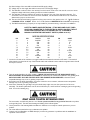
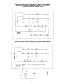
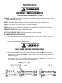
HEAVY HORSEPOWER GRINDER
OPERATING MANUAL & PARTS LIST
Models 342, 542, 548, 552, 7542, 7548, 7552, 1056, 1556
Applicable on HHP Grinders starting with Serial No. 2250
Biro Designed
Biro Built
+
IMPORTANT NOTICE
This Manual contains important
safety instructions which must
be strictly followed when using
this equipment.
+
PTCT
H400-078A
PTCT
4-13-25
H400-078A
7-04-22
NOTICE TO OWNERS AND OPERATORS . . . . . . . . . . . . . . . . . . . . . . . . . . . . . . . . . . . . . . . . . .1
SAFETY TIPS . . . . . . . . . . . . . . . . . . . . . . . . . . . . . . . . . . . . . . . . . . . . . . . . . . . . . . . . . . . . . . . .2
INSTALLATION . . . . . . . . . . . . . . . . . . . . . . . . . . . . . . . . . . . . . . . . . . . . . . . . . . . . . . . . . . . . . . .3
UNCRATING AND SET UP . . . . . . . . . . . . . . . . . . . . . . . . . . . . . . . . . . . . . . . . . . . . . . . . . . .3
MOTOR WIRING . . . . . . . . . . . . . . . . . . . . . . . . . . . . . . . . . . . . . . . . . . . . . . . . . . . . . . . . . . .3
ELECTRICAL REQUIREMENTS . . . . . . . . . . . . . . . . . . . . . . . . . . . . . . . . . . . . . . . . . . . . . . . .4
MOTOR SPECIFICATIONS . . . . . . . . . . . . . . . . . . . . . . . . . . . . . . . . . . . . . . . . . . . . . . . . . . .4
WIRING DIAGRAMS . . . . . . . . . . . . . . . . . . . . . . . . . . . . . . . . . . . . . . . . . . . . . . . . . . . . . . . . . . .5
OPERATION . . . . . . . . . . . . . . . . . . . . . . . . . . . . . . . . . . . . . . . . . . . . . . . . . . . . . . . . . . . . . . . . .6
TO PROCESS PRODUCT . . . . . . . . . . . . . . . . . . . . . . . . . . . . . . . . . . . . . . . . . . . . . . . . . . . .6
CLEANING . . . . . . . . . . . . . . . . . . . . . . . . . . . . . . . . . . . . . . . . . . . . . . . . . . . . . . . . . . . . . . . . . .7
MAINTENANCE . . . . . . . . . . . . . . . . . . . . . . . . . . . . . . . . . . . . . . . . . . . . . . . . . . . . . . . . . . . . . .8
GRINDING BOWL INSTALLATION . . . . . . . . . . . . . . . . . . . . . . . . . . . . . . . . . . . . . . . . . . . . . .8
BEARING HOUSING LUBRICATION . . . . . . . . . . . . . . . . . . . . . . . . . . . . . . . . . . . . . . . . . . . .9
ROLLER CHAIN AND DRIVE SPROCKET LUBRICATION . . . . . . . . . . . . . . . . . . . . . . . . . . . .9
MAIN DRIVE CHAIN TENSION . . . . . . . . . . . . . . . . . . . . . . . . . . . . . . . . . . . . . . . . . . . . . . . . . . .9
OPTIONAL EAGLE DRIVE BELT TENSIONING INSTRUCTIONS . . . . . . . . . . . . . . . . . . . .10 & 11
PARTS DIAGRAMS, MAIN BODY AND DRIVE SYSTEM
FOR 3, 5, 71/2 HORSEPOWER GRINDERS . . . . . . . . . . . . . . . . . . . . . . . . . . . . . . . . . . . . . .12
AND WARNING LABELS & LOCATIONS ON GRINDERS
PARTS DIAGRAMS, BOWL AND TRAY SECTION
FOR 3, 5, 71/2 HORSEPOWER GRINDERS . . . . . . . . . . . . . . . . . . . . . . . . . . . . . . . . . . . . . .13
AND WARNING LABELS & LOCATIONS ON GRINDERS
ELECTRICAL CONTROLS FOR 3, 5, 71/2 HORSEPOWER GRINDERS . . . . . . . . . . . . . . .14 & 15
PARTS DIAGRAMS, MAIN BODY AND DRIVE SYSTEM
FOR 10 & 15 HORSEPOWER GRINDERS . . . . . . . . . . . . . . . . . . . . . . . . . . . . . . . . . . . . . . .16
AND WARNING LABELS & LOCATIONS ON GRINDERS
PARTS DIAGRAMS, BOWL AND TRAY SECTION
FOR 10 & 15 HORSEPOWER GRINDERS . . . . . . . . . . . . . . . . . . . . . . . . . . . . . . . . . . . . . . .17
AND WARNING LABELS & LOCATIONS ON GRINDERS
ELECTRICAL CONTROLS FOR 10 & 15 HORSEPOWER GRINDERS . . . . . . . . . . . . . . . . . . . . .18
OPERATOR’S NOTES . . . . . . . . . . . . . . . . . . . . . . . . . . . . . . . . . . . . . . . . . . . . . . . . . . . .19 & 20
OPERATOR’S SIGNATURE PAGE . . . . . . . . . . . . . . . . . . . . . . . . . . . . . . . . . . . . . . . . . . . . . . . .21
LIMITED WARRANTY . . . . . . . . . . . . . . . . . . . . . . . . . . . . . . . . . . . . . . . . . . . . . . . . . . . . . . . . .22
NOTICE TO OWNERS AND OPERATORS
BIRO’s products are designed to process food products safely and efficiently. Unless the operator is properly trained and supervised, however, there is the possibility of a serious injury. It is the
responsibility of the owner to assure that this machine is used properly and safely, strictly following
the instructions contained in this Manual and any requirements of local law.
No one should use or service this machine without proper training and supervision. All operators should be thoroughly familiar with the procedures contained in this Manual. Even so BIRO
cannot anticipate every circumstance or environment in which its products will be used. You, the
owner and operator, must remain alert to the hazards posed by the function of this equipment –
particularly the ROTATING GRINDING WORM, which can severely injure an inattentive operator
amputating fingers and limbs. No one under eighteen (18) years of age should operate this equipment. If you are uncertain about a particular task, ask your supervisor.
This Manual contains a number of safe practices in the SAFETY TIP section. Additional warnings are placed throughout the Manual. Warnings related to your personal safety are indicated by:
OR
Warnings related to possible damage are indicated by:
BIRO also has provided warning labels on the equipment. If any warning label or Manual becomes misplaced, damaged, or illegible, please contact your nearest Distributor or BIRO directly
for a replacement.
Remember, however, this Manual or the warning labels do not replace the need to be alert and
to use your common sense when using this equipment.
This Manual applies to machines with serial number 2250 and higher.
- NOTE A copy of this manual is included with each HEAVY HORSEPOWER GRINDER.
The descriptions and illustrations contained in this manual are not binding.
The manufacturer reserves the right to introduce any modification
without updating the manual.
1
SAFETY TIPS
ROTATING GRINDING WORM
TO AVOID SERIOUS PERSONAL INJURY
NEVER Touch This Machine Without Training and Authorization By Your Supervisor.
ALWAYS Read Operation and Service Manual BEFORE Operating, Cleaning or Servicing.
NEVER Place Hands Into Machine Input or Output Openings.
NEVER Open Machine During Operation.
ONLY Use a Qualified Electrician to Install According to Local Building Codes: Machine MUST
Be Properly Grounded.
ALWAYS Connect to Proper Voltage & Phase.
ONLY Install on Level, Non-Skid Surface in a Clean, Well-Lighted Work Area Away From
Children and Visitors.
NEVER Use This Machine For Non-Food Products.
NEVER Operate Machine With Tray And/Or Tray Guard Removed, or Magnetic Safety Switch
By-Passed.
ALWAYS Turn Off, Unplug From Power Source and Perform Lockout/Tagout Procedure to This
Machine BEFORE Attempting to Unjam or Unclog, Cleaning or Servicing.
NEVER Leave Machine Unattended While Operating.
NEVER Alter This Machine From its Original Form as Shipped From Factory. DO NOT Operate
Machine With Parts Missing.
PROMPTLY REPLACE Any Worn or Illegible Warning Labels.
USE ONLY BIRO Parts and Accessories Properly Installed.
2
INSTALLATION
TO AVOID SERIOUS PERSONAL INJURY
PROPERLY INSTALL EQUIPMENT IN ADEQUATE WORK AREA
ALWAYS Use Qualified Technician and Electrician for Installation.
ALWAYS Connect to Proper Voltage & Phase.
ALWAYS Install Equipment in Work Area with Adequate Light and Space Away From Children
and Visitors.
ONLY Operate on a Solid, Level, Non-Skid Surface.
NEVER Bypass, Alter, or Modify This Equipment in Any Way From Its Original Condition.
NEVER Operate With Tray And/Or Tray Guard Removed, or Magnetic Safety Switch By-Passed.
NEVER Operate Without all Warning Labels Attached and Owner/Operator Manual Available to
the Operator.
UNCRATING AND SET UP
1. Read this Manual thoroughly before installation and operation. Do not proceed with installation and operation if
you have any questions or do not understand anything in this Manual. Contact your local Distributor, or BIRO
first.
2. Install machine on a level, solid, non-skid surface in a well-lighted work area away from children and visitors.
ALWAYS LEVEL MACHINE BEFORE USING
3. After installing machine in operational area, it is imperative that the four adjusting legs be adjusted to level the
machine and also eliminate rocking.
4. This machine is complete except for a knife and plate. There is a bowl shipping plug (stamped steel) placed in
the output end of the grinding bowl to retain the grinding worm during shipment. REMOVE THE BOWL
SHIPPING PLUG AND THE GRINDING WORM.
5. After checking and making sure the power supply is correct, plug in your machine. NEVER OPERATE
MACHINE WITHOUT TRAY AND GUARD INSTALLED (Machine will not run with tray removed).
6. Machine must be properly grounded. Use qualified electrician to install according to building codes.
MOTOR WIRING AND ELECTRICAL REQUIREMENTS
(A) Interchange of current is made in motor outlet box. Leads are properly marked. Changing instructions are
on the motor plate or motor outlet box.
(B) All grinders are wired 220 volts unless otherwise specified. Be sure motor specifications (voltage, cycle,
phase) match power supply line. Be sure line voltage is up to specification.
(C) Electrical connections to be accordance with safety codes and National Electrical Code.
3
(D) Rated voltage of the unit shall be identical with full supply voltage.
(E) Voltage drop on the supply line shall not exceed 10% of full supply voltage.
(F) The feederline conductor size in the raceway from the branch circuit to the unit must be correct to assure
adequate voltage under heavy starting and short overload conditions.
(G) The feederline conductor shall only be used for the supply of one unit of the relevant horsepower. For
connections of more than one unit on the same feederline, a local electrician will have to be consulted to
determine the proper conductor size.
(H) The size of the electrical wiring required from the power source to the grinder on the 3, 5, 71 2 HP Grinders is
a MINIMUM OF No. 10 WIRE. On the 10 & 15 HP Grinders a MINIMUM OF No. 8 and No. 6 respectively.
(I) The BIRO Manufacturing Company is not responsible for permanent wiring, connection or installation.
NOTE TO OWNER AND ELECTRICIAN: IF THIS MACHINE IS NOT CORD
AND PLUG CONNECTED TO THE ELECTRICAL SUPPLY SOURCE, THEN IT
SHOULD BE EQUIPPED WITH, OR CONNECTED TO, A LOCKABLE,
MANUALLY-OPERATED DISCONNECT SWITCH (OSHA 1010.147).
MOTOR SPECIFICATIONS
HP
KW
VOLTS
HZ
PH
AMPS
5
4
208/220
60
3
17/16
5
4
230
60
1
27
5
4
440
60
3
8
5
4
550
60
3
6.4
7.5
5.5
208/220
60
3
23/22
7.5
5.5
440
60
3
11
10
7.5
208/220
60
3
27/25.6
10
7.5
440
60
3
12.8
10
7.5
550
60
3
10
15
11
208/220
60
3
41/39
15
11
440
60
3
19.5
7. Located on the side of the machine is a toggle handle that activates the internal on/off switch. The interlock
safety switch is mounted to the top of the internal switch and will break contact with the magnetic starter should
the tray be removed.
8. Turn the toggle handle to the “ON” position. CHECK THE ROTATION OF THE WORM DRIVE SHAFT;
ROTATION MUST BE COUNTER-CLOCKWISE as indicated by the rotation decal affixed to the grinding bowl.
ROTATION MUST ONLY BE CHECKED WITH THE GRINDING WORM REMOVED, otherwise serious
irreparable damage may occur to grinding components.
9. If machine runs clockwise (backwards), it must be rewired to correct rotation, otherwise serious irreparable
damage may occur to grinding components.
10. Insert worm assembly into grinding bowl, place knife (sharp edges out) onto the square end of the worm
assembly. The breaker plate slides over the worm knife drive pin, and is held from rotating by pins in the grinding
bowl. Put on the retaining ring.
ONLY HAND TIGHTEN RETAINING RING
For best results, use knife and plate as a set. Do not operate machine for any period of time without product
in the grinding bowl. This will cause heating and dulling of the knife and plate.
11. Check placement of all warning labels and Manual. Machine is now ready for trained operators to process
product.
12. Use meat deflector attached to tray to eliminate meat splatter.
13. Contact your local Distributor or BIRO directly if you have any questions or problems with the installation or
operation of this machine.
4
WIRING DIAGRAM FOR HEAVY HORSEPOWER MANUAL FEED GRINDERS
EQUIPPED WITH AEG OR STROMBERG STARTER (3, 5, 712 HP ONLY)
STARTING WITH SERIAL NUMBER 24808
WIRING DIAGRAM FOR HEAVY HORSEPOWER MANUAL FEED GRINDERS
EQUIPPED WITH AEG OR STROMBERG STARTER (10,15 HP ONLY)
5
OPERATION
ROTATING GRINDING WORM
TO AVOID SERIOUS PERSONAL INJURY
ONLY Properly Trained Personnel Should Use This Equipment.
NEVER Place Hands Into Machine Input or Output Openings.
NEVER Open Machine During Operation.
DO NOT Wear Gloves While Operating.
DO NOT Tamper With, Bypass, Alter, or Modify This Equipment in Any Way From Its Original
Condition.
NEVER Operate Machine With Tray And/Or Guard Removed, or Magnetic Safety Switch
By-Passed.
ALWAYS Turn Off, Unplug From Power Source and Perform Lockout/Tagout Procedure to This
Machine Before Unjamming, Unclogging, Cleaning or Servicing.
NEVER Leave Unattended While Operating.
NEVER Operate Without All Warning Labels Attached and Owner/Operator Manual Available to
the Operator.
A. TO PROCESS PRODUCT
1. Before starting grinder, have meat stomper within easy reach and method of receiving ground product
located at output end of grinding bowl.
2. Turn toggle to “ON” position. Look down grinder bowl and make certain grinding worm is turning in the
proper direction (counter-clockwise).
3. Carefully push unground product to top opening of grinding bowl and let drop to grinding worm. Product will
then be ground out.
DO NOT REACH DOWN BOWL OPENING
4. Use meat stomper to assist any product that should “bridge up” in grinding bowl opening.
5. When finished grinding turn toggle handle to “OFF” position and unplug grinder from power source and
perform lockout/tagout procedure.
DO’S
• Always keep knife & plate as matched set.
• Always keep the knife & plate sharp.
• Always check for levelness by laying the knife on
the plate before inserting in machine.
• Always install the knife & plate in correct sequence,
knife 1st then plate.
• Always keep knives & plates lubricated in storage and
when starting up machine.
• Always use coolant when sharpening plates.
• Always inspect the plates making sure all holes are clearthat there are no cracks.
DON’Ts
• Never, never mix different knives to different plates.
• Never, never over tighten the bowl retaining ring on the
machine.
• Never, never run the grinder/mincer without product.
6 Product is a natural lubricant. Heat can build up so fast that
cold product could crack the plate.
• Never, never hit the plate against anything to clean the holes.
• Never, never throw the knives & plates.
6
MAINTENANCE
ROTATING GRINDING WORM
TO AVOID SERIOUS PERSONAL INJURY
ALWAYS Turn Off, Unplug From Power Source and Perform Lockout/Tagout Procedure to This
Machine BEFORE Servicing.
NEVER Touch This Machine Without Training and Authorization By Your Supervisor.
NEVER Place Hands Into Machine Input or Output Openings.
NEVER Bypass, Alter, or Modify This Equipment in Any Way From Its Original Condition.
PROMPTLY REPLACE Any Worn or Illegible Labels.
USE ONLY GENUINE BIRO Parts and accessories Properly Installed.
A. GRINDING BOWL INSTALLATION
1. Mount the grinding bowl on the two threaded studs on the front of the machine. Tighten in position with
provided nuts.
2. Place the grinding worm in the grinding bowl and fully seat rear drive tang into worm drive shaft.
3. Install knife, breaker plate and end retaining ring.
ONLY HAND TIGHTEN RETAINING RING
4. When the bowl assembly is mounted and tight, there should be approximately 1 8" gap between the back
inside wall of the bowl and the back of the worm (SEE FIGURE 1). The bowl ring wrench which is provided
with each grinder is used only for REMOVAL of the end retaining ring for cleaning purposes or for changing
knife and breaker plate.
5. To check wear: With bowl assembly removed, place a straight edge across outside flange of aluminum
bearing housing. The end of the worm drive shaft should just contact the straight edge, i.e. flange face and
worm drive shaft end should be in the same plane (SEE FIGURE 2).
8
B. BEARING HOUSING LUBRICATION
1. Unplug grinder from power source and perform lockout/tagout procedures.
2. Remove bolted on tray.
3. Check and relubricate with good grade of lithium bearing grease semi-annually.
4. Reinstall tray and bolt on tightly.
C. ROLLER CHAIN AND DRIVE SPROCKET LUBRICATION
Chains should be protected against dirt and moisture. Chain life will vary appreciably depending upon its lubrication. The better the lubrication, the longer the chain life.
Lubrication effectiveness will vary with the amount of lubrication and frequency of application. Ideally, a lubricant
film should always be present between the working parts. Manually lubricate the chain after the 1st six weeks then every 6 months thereafter.
Lubricating just the outside of the chain does little good. Apply lubrication on the inside of the chain span so that
it will work through the moving parts and joints by centrifugal force as the chain rotates and reach the area where one
surface “scrubs” another.
Recommended types of chain lubricant are those with Molybdenum Disulphide or Graphite added. Also bonded
lubricants such as Dow Corning’s Molykote 321R or equivalent are excellent for open chains. The lubricant should be
of a viscosity whereby it will “flow” somewhat and penetrate the internal working surfaces. Thick stiff greases are of little value because they cannot work into moving parts of the chain.
Symptoms of Inadequate Lubrication:
1. Excessive noise
2. Chain becomes stiff
3. Chain runs hot
4. Broken pins, bushings or rollers
5. Excessive chain elongation — caused by wear on the pin outside diameter and pushing inside diameter
Once a chain is elongated or worn past acceptable limits, jumping of sprocket teeth and/or improper
chain/sprocket mesh will occur.
LUBRICATING CHAIN AND SPROCKETS
1. Unplug grinder from power source and perform lockout/tagout procedures.
2. Remove bolted on tray.
3. Spray or brush lubricant on inside of chain, slowly and carefully turning large sprocket by hand.
4. Reinstall tray and bolt on tightly.
D. MAIN DRIVE CHAIN TENSION LUBRICATING CHAIN AND SPROCKETS
1. Unplug grinder from power source and perform lockout/tagout procedure.
2. Remove feed tray.
3. Loosen motor mounting bolts.
4. Remove shims from under the motor. Important to remove same shims from back of motor as from the front for
proper sprocket alignment.
5. Total chain flex should be 1 8" to 3 8" for proper chain tension. Do not over tension as this can cause excessive
wear or premature failure of motor bearings and journal box bearings.
6. Retighten all motor mounting bolts.
7. Reinstall feed tray.
9
OPTIONAL EAGLE BELT DRIVE SYSTEM
BIRO MANUAL FEED GRINDERS
MODELS 548,552,7548,7552,1056,1556
10
11
IMPORTANT: Must have Model and Serial Number when ordering Parts
MAIN BODY AND DRIVE SYSTEM FOR
3, 5 AND 712 HORSEPOWER GRINDERS
Applicable on Choppers Starting with Serial No. 2250
Part No.
Description
H301 . . . . . . . . . . . . Bearing box, aluminum
H301A . . . . . . . . . . . . Bearing box assembly
H302 . . . . . . Main drive shaft, 23 8 ´ 151 4 long
H303 . . . . . . . . . . Shaft collar, 25 8 ´ 11 4 long
H304 . . . . . . . . . . . . Shaft nut, 23 8 ´ 11 4 long
H305 . . . . . . . . . . . . . Shaft spacer, 23 8 ´ 11 2
H306 . . . . . . . . . . . . . . . . . . Grease brg. box
H307 . . . . . . . . Bearing box grease fitting, 1 8
H308. . . . . . . . . Main shaft key, 3 8 ´ 39 16 long
H309 . . . . . . . . . . . . . . . . . . . . . . . . . . . Seal
H310A . . . . . . . . . . . . . . . Front bearing cup
and cone assembly
H311A . . . . . . . . . . . . . . . . Rear bearing cup
and cone assembly
H313. . . . . . . . . . . . . . . . Bowl studs, 1 2 ´ 31 4
H317 . . . . . . . . . . . . . . . . . Switch rod, 203 4L
H317-1 . . . . Switch rod 201 8L after s/n 27182
H318 . . . . . . . . . . . . . Aluminum switch cam
(Ser. 9039 to 11260)
H318-1 . . . . . . . . . . . . . . Switch cam, nylon
(before 9039 & after 11260)
H319 . . . . . . . . . . . . . . . . . . . Switch handle
H322 . . . . . . . . . . . . . Connection box cover
H324. . . . . . . . . . . . . . . Base fee, 11 2", black
pipe coupling
H325A . . . . . . . . . . . . . Base plate assembly
H327-11 . . . . . . . . . Aluminum legs, 11 2 ´ 11
H328. . . . . . . . . . . . . . . . . Switch lock collar
H331 . . . . . . . . . . . . . . . . . . . Roll pin, 1 8 ´ 5 8
H333 . . . . . . . . Model & serial number plate
H335A. . . . . . . . . . . . . . . Bevel collar trim 8"
w/fastener
H346 . . . . . . . . . . . . . . . . . . Connection box
H366 . . . . . . . . . . 1 2-13 hex nut, bowl & bowl
stud locknut
H382 .. .. . . ..Hex
. Motor
19-tooth
- 60
Hz
H367.
Headpinion
Screw–5/8
11 x 2”
Long
H382-1
tooth
for 50Hz
H368
. . .. .. ... Motor
. . . . . pinion
. . . . . .–. 22
. Lock
Washer
5/8
H383 .. .. .. .. .. .. .Motor
. . . . .pinion
. . Sprocket
– 141
tooth
H382
– 19 tooth
- 60
Hz
H384-CL. .. 35-4
roller
chain
w/connecting
link
H382-1
. Motor
pinion
– 22
tooth for 50Hz
H384-1
. . . . . SEE
INSERT
H383
. . .. .. .. .. .. .. .. .. .. .. .. .. .Sprocket
– 141
tooth
H384-2 . 35-4 roller chain w/connecting
“A” ATlink
H384-CL
H384-3 . . . . . . . . . . . . . . . . . . SEE
RIGHT
H384-1
INSERT
H386A . . . . . . . . . . . . . . . SS case“A”
assembly
H384-2
AT
5 -18
H389-1.
.
.
.
.
.
.
.
.
.
.
Carriage
bolt,
16
H384-3
RIGHT ´ 4
1 -13 motor attachment
H390
.
.
.
.
.
Hex
nut,
2
H386A . . . . . . . . . . . . . . . SS case assembly
H406 . . .. .. .. .. .. .. .. .. .. .. Carriage
. . . . . Grease
chain
H389-1.
bolt, 5for
16-18 ´ 4
H425 .. .. .. .. .. Hex
. . . .nut,
. . . 1. .-13
. Motor
2" ´ 11"
H390
motorshim
attachment
2
7
H432 .. .. .. .. .. .. .. .. .. .. .. .. Box
bowl wrench
H406
. . . .end
. Grease
for chain8
H462
.
.
.
.
.
.
.
.
.
.
.
.
Guard
for
switch
toggle
H425 . . . . . . . . . . . . . . . Motor shim 2" ´ 11"
H462-1
. . . .end
. . . bowl
. Guard
ferrule
7
H432
. . .. .. .. .. .. .. .. .. .. .. Box
wrench
8
5 -18
H476 .. .. .. .. .. .. .. .. .. .. .. .. .Guard
. . . . Hex
nut SStoggle
16
H462
for switch
H591
.
.
.
.
.
.
.
.
.
.
.
.
.
.
.
Bushing,
switch
rod
H462-1 . . . . . . . . . . . . . . . . . . Guard ferrule
H591-1
Bushing
lock
nut
5 -18
H476
. . .............................. Hex
nut SS
16
H592.. .. .. .. .. .. Star
switch rod
bushing
H591
. . . . washer,
. . . . . Bushing,
switch
rod
H653-E .. .. .. .. .. .. .. .. .. .. .. .Warning
label,lock
English
H591-1
. . . Bushing
nut
H653-SP.
. . . washer,
. . . Warning
Spanish
H592.
. . . .. .. .Star
switchlabel,
rod bushing
H653-E . . . . . . . . . . . Warning label, English
H653-SP. . . . . . . . . . Warning label, Spanish
}
}
Motor Section
Part No.
Description
H379. . . . . . . . . . . . . 3 hp, 220/440-50/60-3
H380-U . . . . . . . . . . . 5 hp, 220/440-50/60-3
H380-5B . . . . . . . . . . . . . 5 hp, 230-50/60-1
H381-U . . . . . . . . . 71 2 hp, 220/440-50/60-3
NOT SHOWN
14572 . . . . . . . . . . . . . . Ring wrench hanger
INSERT A
To convert machines S/N2250
to 3173 equipped with 2"
Silent Chain, 21 2 " Silent
Chain, or 35-3 Roller Chain will
require:
1 Ea. H382 Motor Sprocket
1 Ea. H383 Main Sprocket
1 Ea. H384-CL 35-4 Roller Chain
w/Connecting Link
H653-E
H386A
H333
H367
H368
12
10
H653-SP
IMPORTANT: Must have Model and Serial Number when ordering Parts
MAIN BODY AND DRIVE SYSTEM FOR
3, 5 AND 712 HORSEPOWER GRINDERS
Applicable on Choppers Starting with Serial No. 2250
GRINDER HORSEPOWER AND BOWL SIZE AVAILABLE
Model 342 — 3 HP — #42 size bowl — tinned
Model 548 — 5 HP — #48 size bowl — tinned
Model 552 — 5 HP — #52 size bowl — tinned
Model 7548 — 7.5 HP — #48 size bowl — tinned
Model 7552 — 7.5 HP — #52 size bowl — tinned
48 Bowl Section
42 Bowl Section
Part Number
Description
HC42A . . . . . . . . . . . . . . . . . Bowl Assembly
HC42 . . . . . . . . . . . . . . . . . . . . . . . . . . Bowl
HS42A . . . . . . . . . . . . . . . . Worm assembly
HR42/48 . . . . . . . . . . . . . . . . . . . . . . . . Ring
HK48 . . . . . . . . . . . . . . . . . . . Knife drive pin
HP48 . . . . . . . . . . . . . . . . . . . . . . . Bowl Pin
H340. . . . . . . . . . . . . Aluminum ring wrench
Part Number
52 Bowl Section
Description
HC48A . . . . . . . . . . . . . . . . . Bowl assembly
HC48 . . . . . . . . . . . . . . . . . . . . . . . . . . Bowl
HS48A . . . . . . . . . . . . . . . . Worm assembly
HR42/48 . . . . . . . . . . . . . . . . . . . . . . . . Ring
HK48 . . . . . . . . . . . . . . . . . . . Knife drive pin
HP48 . . . . . . . . . . . . . . . . . . . . . . . Bowl pin
H340. . . . . . . . . . . . . Aluminum ring wrench
Part Number
Description
HC52A . . . . . . . . . . . . . . . . . Bowl assembly
HC52 . . . . . . . . . . . . . . . . . . . . . . . . . . Bowl
HS52A . . . . . . . . . . . . . . . . Worm assembly
HR52 . . . . . . . . . . . . . . . . . . . . . . . . . . Ring
HK52 . . . . . . . . . Knife drive pin, fine thread,
to #26795
HK52/56 . . . . Knife drive pin, coarse thread,
#26796 on
HP52 . . . . . . . . . . . . . . . . . . . . . . . Bowl pin
H340. . . . . . . . . . . . . Aluminum ring wrench
Tray Section For
3, 5, 7 Horsepower
Part Number
Description
H339-1. . . . . . . . . . . Spurt guard for SS tray
H388-1A . . . . . . Left hand tray assembly, SS
H388-2A . . . . . Right hand tray assembly, SS
H338-SFT-2A . . . . . . . . . Tray guard assem.
for SS tray
H387 . . . . . . . . Tray angles, .0625 ´ 13 4 ´ 29
H389-1. . . . . . . . . . . Carriage bolt, 5 16-18 ´ 4
H404SFT . . . . . . . . . . . Stomper, 121 2" long
H404SFT-SLD . . . . . . . Solid stomper, 121 2"
H407 . . . . . . . . . . . Wing nut, 3 8 SS tray only
H441 . . . . . . . . . . . . . . . . . . . Warning decal
H476 . . . . . . . . . . . . . . . . . Hex nut SS 5 16-18
H477 . . . . . . . . . . SS stand off for tray guard
H512 . . . . . . . . . . . . . . . . . . Magnet housing
H512-1. . . . . . . . . Magnet ser. no. 26628 on
H404SFT
BOWL, RING, & WORM IDENTIFICATION
ALL DIMENSIONS IN INCHES
11-13/16
13
11
15-3/8
15-1/16
IMPORTANT: Must have Model and Serial Number when ordering Parts
ELECTRICAL CONTROLS
3, 5 AND 712 HORSEPOWER GRINDERS
FROM SERIAL NO. 2250 TO
SERIAL NO. 5239
FROM SERIAL NO. 9039 TO
SERIAL NO. 11260
ORIGINALLY EQUIPPED WITH ALLEN BRADLEY
609-BAA MANUAL STARTER WITHOUT MAGNETIC
SAFETY SWITCH. THESE SWITCHES ARE OBSOLETE AND MUST BE UPDATED TO THE APPROPRIATE AEG EQUIVALENT. ORDER H478AE
(SPECIFY HP AND VOLTS TO COMPLETE
NUMBER). AEG SWITCH ASSEMBLY MUST BE INSTALLED BY A QUALIFIED BIRO SERVICE
AGENCY.
ORIGINALLY EQUIPPED WITH ALLEN BRADLEY
609U-BAA MANUAL STARTER WITH MAGNETIC
SAFETY SWITCH. THESE SWITCHES ARE OBSOLETE AND MUST BE UPDATED TO THE APPROPRIATE AEG EQUIVALENT. ORDER H478AE
(SPECIFY HP AND VOLTS TO COMPLETE
NUMBER). AEG SWITCH ASSEMBLY MUST BE INSTALLED BY A QUALIFIED BIRO SERVICE
AGENCY.
CONVERSION TO
AEG STARTER
FROM SERIAL NO. 2250 TO SERIAL
NO. 11260 WHEN REPLACING AN
ALLEN
BRADLEY
SERIES
609
STARTER WITH AN AEG STARTER.
NEW HOLE LOCATIONS MUST BE
DRILLED IN THE MACHINE CASE FOR
MOUNTING THE STARTER AND RELOCATING THE SWITCH ROD AS
SHOWN IN THE DIAGRAM.
14
12
FROM SERIAL NO. 5240 TO
SERIAL NO. 9038 AND SERIAL NO.
11281 TO SERIAL NO. 24807
SERIAL NO. 24808 TO 26493
ORIGINALLY EQUIPPED WITH ALLEN BRADLEY
709-BAA MAGNETIC STARTER WITH MAGNETIC
SAFETY SWITCH AND AN ALLEN BRADLEY
800S-2SA
START-STOP
STATION.
THE
START-STOP STATION IS STILL AVAILABLE, BUT
THE 709-BAA IS OBSOLETE AND NOT AVAILABLE. UNITS REQUIRING REPLACEMENT OR REPAIR
MUST
BE
UPDATED
WITH
THE
APPROPRIATE AEG STARTER. ORDER H478AE
(SPECIFY HP & VOLTS TO COMPLETE NO.)-LB.
AEG SWITCH ASSEMBLY LESS BUTTONS. THIS
SWITCH ASSEMBLY MUST BE INSTALLED BY A
QUALIFIED BIRO SERVICE AGENCY.
ORIGINALLY EQUIPPED WITH STROMBERG
STARTER WITH PUSH BUTTONS AND MAGNETIC
SAFETY SWITCH AS ONE UNIT. THE STROMBERG
STARTER AND INTERNAL COMPONENTS ARE NO
LONGER AVAILABLE. REPLACEMENT REQUIRES
UPDATE TO APPROPRIATE AEG EQUIVALENT.
SERIAL NO. 24808 TO PRESENT
EQUIPPED WITH AEG STARTER WITH PUSH BUTTONS AND MAGNETIC SAFETY SWITCH AS ONE
UNIT.
Part Number
Part Number
AEG Switch Section
AEG Switch Section
Description
H318. . . . . . . Switch cam, aluminum (#2250-5239 & #9039-11280)
H318-1 . . . . . . . . . . . . . . . . . . . . . . . . . . . . . . . . . Switch cam, nylon
42MC-Y64 . . . . . . . . . . . . . . . . . . Magnetic safety switch, low voltage
H442-1 . . . . . . . . . . . . . . . . . . . . Magnetic safety switch, high voltage
H457 . . . . . . . . . . . . . . . . . . . . . . . . . . . . . . . . . . Square head screw
H478AE-21A. . . . . . . . . . . Switch assembly BAEG/3-C12 (208/220V)
H478AE-22A. . . . . . . . . . . . Switch assembly BAEG/3-D6 (380/415V)
H478AE-23A . . . . . . . . . . . . . . . Switch assembly BAEG/3-E6 (440V)
H478AE-24A . . . . . . . . . . . . . . . Switch assembly BAEG/3-F6 (550V)
H478AE-25A. . . . . . . . . . . Switch assembly BAEG/5-C17 (208/220V)
H478AE-26A. . . . . . . . . . . Switch assembly BAEG/5-D12 (380/415V)
H478AE-27A . . . . . . . . . . . . . . Switch assembly BAEG/5-E12 (440V)
H478AE-28A . . . . . . . . . . . . . . . Switch assembly BAEG/5-F8 (550V)
H478AE-29A . . . . . . . . . Switch assembly BAEG/5S-C32 (230V-1PH)
H478AE-30A . . . . . . . . . Switch assembly BAEG/7.5 C23 (208/220V)
H478AE-31A . . . . . . . . . Switch assembly BAEG/7.5-D17 (380/415V)
H478AE-32A . . . . . . . . . . . . . Switch assembly BAEG/7.5-E17 (440V)
H478AE-33A . . . . . . . . . . . . . Switch assembly BAEG/7.5-F12 (550V)
H479AE-220 . . . . . . . . . . . . . Contactor SP27.10-C0 (208/220/230V)
H479AE-380 . . . . . . . . . . . . . . . . Contactor SP27.10-D0 (380/415V)
H479AE-440 . . . . . . . . . . . . . . . . . . . . Contactor SP27.10-E0 (440V)
H479AE-550 . . . . . . . . . . . . . . . . . . . . Contactor SP27.10-F0 (550)V
H481AE-51 . . . . . . . . . . . . . . Overload B27S-K (3HP-380/440/550V)
H481AE-52 . . . . . . . . . . . . . . . . . . . . . Overload B27S-L (5HP-550V)
H481AE-53 . . . . . . . . . . . . . . . . . . . . . . . . . . . . . . Overload B27S-M
(3HP-220V; 5HP-380/415/440V) (7.5HP-550V)
H281AE-31 . . . . . . . . . . . . . . . . . . . . . . . . . . . . . . Overload B27S-N
(5HP-220V; 7.5HP-380/415/440V) (10HP-380/415/440/550V)
H281AE-32 . . . . . . . . . . . . . . . . . . . . . . . . . . . . . . Overload B27S-O
(7.5PH-220V) (15HP-380/415/440/550V)
H281AE-33 . . . . . . . Overload B27S-P (5HP-230V-1PH; 10HP-220V)
H478AE-ENCL-PB. . . . . . . WT enclosure w/button holes (3/5/7.5HP)
H482-1. . . . . . . . . . . . . . . . . . . . . . . . Green Push Button (3,5,71 2HP)
H482-2 . . . . . . . . . . . . . . . . . . . . . . . . . Red Push Button (3,5,71 2HP)
Description
H318-1 . . . . . . Switch cam, nylon #5240-9038 & #11281 to present
42MC-Y64 . . . . . . . . . . . . . . . . . . Magnetic safety switch, low voltage
H442-1 . . . . . . . . . . . . . . . . . . . . Magnetic safety switch,high voltage
H478AE-21A-LB . . . . . . . . . . . . . . . . . Switch assembly less buttons
BAEG/3-C12 (3HP-208/220/230V)
H487AE-23A-LB . . . . . . . . . . . . . . . . . Switch assembly less buttons
BAEG/3-E6 (3HP-440V)
H478AE-25A-LB . . . . . . . . . . . . . . . . . Switch assembly less buttons
BAEG/5-C17 (5HP-208/220/230V)
H478AE-27A-LB . . . . . . . . . . . . . . . . . Switch assembly less buttons
BAEG/5-E12 (5HP-440V)
H478AE-30A-LB . . . . . . . . . . . . . . . . . Switch assembly less buttons
BAEG/7.5-C23 (7.5HP-208/220/230V)
H478AE-32A-LB . . . . . . . . . . . . . . . . . Switch assembly less buttons
BAEG/7.5-E17 (7.5HP-440V)
15
13
IMPORTANT: Must have Model and Serial Number when ordering Parts
MAIN BODY AND DRIVE SYSTEM
FOR 10 AND 15 HORSEPOWER GRINDERS
Applicable on Choppers Starting with Serial No. 2250
Part No.
Description
H101 . . . . . . . . . . . . . . . . . . . . . Bearing box
H101A . . . . . . . . . . . . Bearing box assembly
H102 . . . . . . . . Main drive shaft, 31 4 rd ´ 151 2
H103 . . . . . . . . . . . . . . . Shaft collar, 31 4 ´ 1
H104 . . . . . . . . . . . . . . . . Shaft nut 31 4 ´ 11 4
H105 . . . . . . . . . . . . . . Shaft spacer 31 4 ´ 11 4
H109 . . . . . . . . . . . . . . . . . . . . . . . . . . . Seal
H110A . . . . . . . . . . . . . . . Front bearing cup
& cone assembly
H111A . . . . . . . . . . . . . . . . Rear bearing cup
& cone assembly
H113 . . . . . . . . . . . . . . . Bowl stud 3 4-10 ´ 4
H117 . . . . . . . . . . . . . . . . . Switch rod, 241 4L
H117-1 . . . Switch rod 235 8L after s/n 27192
H125A . . . . . . . . . . . . . Base plate assembly
H127S-6 . . . . . . . . . . . . . . Steel legs, 11 2 ´ 6
H135A . . . . . . . . . . . . Bevel collar trim — 10
w/fastener
H182. . . . . . Motor pinion – 17 tooth – 60 Hz
H182-1 . . . . Motor pinion – 21 tooth – 50Hz
H183 . . . . . . . . . . . . . . . 128 tooth sprocket
H184 . . . . . . . . . . . . . . . . . . . 3" silent chain
H184-1 . . . . . . . . . . . . Master link 1 2 pitch 3"
H186A . . . . . . . . . . Case assembly, stainless
H222 . . . . . . . . . . . Hex nut for bowl stud, 3 4
H224 . . . . . . . . . . . . . Motor shim, 1 ´ 2 CF,
11" long, 10, 15 HP
H225 . . . . . . . . . . . . Motor Shim, 1 8 ´ 2 ´ 11
(use H425)
H232 . . . . . . . . . . . . . . . Box end wrench, 1"
H306 . . . . . . . . . . . . . . . . . Grease, brg. box
H307 . . . . . . . . . Bearing box grease fitting,
H308 . . . . . . . . . . . . Main shaft key, 3 long
H318-1 . . . . . . . . . . . . . . Switch cam, nylon
H319 . . . . . . . . . . . . . . . . . . . Switch handle
H322 . . . . . . . . . . . . . Connection box cover
H324 . . . . . . . . . . . . . . Base feet, 11 2", black
pipe coupling
H328 . . . . . . . . . . . . . . . . . Switch rod collar
H331 . . . . . . . . . . . . . . . . . . . Roll pin, 1 8 ´ 5 8
H333 . . . . . . . . Model & serial number plate
H346 . . . . . . . . . . . . . . . . . . Connection box
H389-1. . . . . . . . . . . Carriage bolt, 5 16-18 ´ 4
H390 . . . . . Hex nut, 1 2-13 motor attachment
H406 . . . . . . . . . . . . . . . . . Grease for chain
H462 . . . . . . . . . . . . Guard for switch toggle
H462-1 . . . . . . . . . . . . . . . . . . Guard ferrule
H476 . . . . . . . . . . . . . . . . . Hex nut SS 5 16-18
H591 . . . . . . . . . . . . . . . Bushing, switch rod
H591-1 . . . . . . . . . . . . . . . Bushing lock nut
H592. . . . . . Star washer, switch rod bushing
H653-E . . . . . . . . . . . Warning label, English
H653-SP. . . . . . . . . . Warning label, Spanish
Motor Section
Part No.
Description
H179-U . . . . . . . . . . 10 hp, 220/440-50/60-3
H180-B . . . . . . . . . . 15 hp, 220/440-50/60-3
NOT SHOWN
14572 . . . . . . . . . . . . . . Ring wrench hanger
H653-E
H653-SP
H333
16
14
16-25/32
18-11/16
17
IMPORTANT: Must have Model and Serial Number when ordering Parts
ELECTRICAL CONTROLS
10 AND 15 HORSEPOWER GRINDERS
AEG Switch Section
FROM SERIAL NO. 2250
TO SERIAL NO. 24729
Part Number
ORIGINALLY EQUIPPED WITH ALLEN BRADLEY
709-BAA MAGNETIC STARTER WITH MAGNETIC
SAFETY SWITCH AND AN ALLEN BRADLEY
800S-2SA
START-STOP
STATION.
THE
START-STOP STATION IS STILL AVAILABLE, BUT
THE 709-BAA IS OBSOLETE AND NOT AVAILABLE. UNITS REQUIRING REPLACEMENT OR REPAIR
MUST
BE
UPDATED
WITH
THE
APPROPRIATE AEG STARTER. ORDER H278AE
(SPECIFY HP & VOLTS TO COMPLETE NO.) AEG
SWITCH ASSEMBLY. THIS SWITCH ASSEMBLY
MUST BE INSTALLED BY A QUALIFIED BIRO SERVICE AGENCY.
FROM SERIAL NO. 24780
TO SERIAL NO. 26586
ORIGINALLY EQUIPPED WITH STROMBERG
STARTER WITH MAGNETIC SAFETY SWITCH AND
AN ALLEN BRADLEY 800S-2SA START-STOP
STATION. THE START-STOP STATION IS STILL
AVAILABLE, BUT THE STROMBERG STARTER AND
INTERNAL COMPONENTS ARE NO LONGER
AVAILABLE. REPLACEMENT REQUIRES UPDATE
TO APPROPRIATE AEG EQUIVALENT.
FROM SERIAL NO. 24780
TO PRESENT
EQUIPPED WITH AEG MAGNETIC STARTER AND
AN ALLEN BRADLEY 800S-2SA START-STOP
STATION.
18
16
Description
H277. . . . . . . . . . . SO Cord, 16/4 (10, 15HP
push button to starter)
H278AE-11A . . . . . . . . . . Switch Assembly,
BAEG/10-C32 (220V)
H278AE-12A . . . . . . . . . . Switch Assembly,
BAEG/10-D17 (380/415V)
H278AE-13A . . . . . . . . . . Switch Assembly,
BAEG/10-E17 (440V)
H278AE-14A . . . . . . . . . . Switch Assembly,
BAEG/10-F17 (550V)
H278AE-15A . . . . . . . . . . Switch Assembly,
BAEG/15-C50 (220V)
H278AE-16A . . . . . . . . . . Switch Assembly,
BAEG/15-D23 (380/415V)
H278AE-17A . . . . . . . . . . Switch Assembly,
BAEG/15-E23 (440V)
H278AE-18A . . . . . . . . . . Switch Assembly,
BAEG/15-F23 (550V)
H279AE-220. . . . . . . Contactor SP37.10-C0
(208/220/230V)
H279AE-380 . . . . . . Contactor SP37.10-D0
(380/415V)
H279AE-440. . . . . . . Contactor SP37.10-E0
(440V)
H279AE-550. . . . . . . Contactor SP37.10-F0
(550V)
H281AE-31 . . . . . . . . . . . Overload B27S-N
(5HP-220V; 7.5HP-380/415/440V)
(10HP-380/415/440/550V)
H281AE-32 . . . . . . . . . . . Overload B27S-O
(5HP-220V)
(15HP-380/415/440/550V)
H281AE-33 . . . . . . . . . . . . Overload B27S-P
(5HP-230V-1PH; 10HP-220V)
(10HP-380/415/440/550V)
H281AE-34 . . . . . . . . . . Overload B77S-QN
(15HP-220V)
H278AE-ENCL . . . . . . . . . . . . WT enclosure
less button holes (10/15HP)
H318-1 . . . . . . . . . . . . . . Switch cam, nylon
(before 9039 & 11281 to present)
H348 . . . . . . . Push button station 800S2SA
42MC-Y64 . . . . . . . . Magnetic safety switch,
low voltage
H442-1 . . . . . . . . . . . Magnetic safety switch,
high voltage
– OPERATOR’S NOTES –
19
– OPERATOR’S NOTES –
20
OPERATOR'S SIGNATURE PAGE
WARNING
READ AND UNDERSTAND THIS ENTIRE
MANUAL BEFORE SIGNING BELOW
MY SIGNATURE ATTESTS THAT I HAVE COMPLETELY READ AND UNDERSTAND THIS MANUAL.
I REALIZE THAT THIS MACHINE, IF OPERATED CARELESSLY, CAN CAUSE SERIOUS INJURY TO
MYSELF AND OTHERS.
NAME (PRINT)
SIGNATURE
21
17
SUPERVISOR’S
INITIALS
DATE
LIMITED WARRANTY
WARRANTY: The BIRO Manufacturing Company warrants that the BIRO Heavy Horsepower
Grinder will be free from defects in material and workmanship under normal use and with recommended service. BIRO will replace defective parts, which are covered by this limited warranty, provided that the defective parts are authorized for return, shipping charges prepaid, to a designated
factory for inspection and/or testing.
DURATION OF WARRANTY: The warranty period for all parts covered by this limited warranty is
one (1) year from date of Inspection/Demonstration advised on the returned Warranty Registration
card, or eighteen (18) months from original factory ship date, whichever occurs first, except as
noted below.
PARTS NOT COVERED BY WARRANTY: The following are not covered by this limited warranty:
wearable parts in the grinding system such as bowl, ring, worm, drive shaft, and knife drive pin.
This limited warranty does not apply to machines sold as used, rebuilt, modified,or altered from
the original construction in which the machine was shipped from the factory. (WATER CONTAMINATED ELECTRICAL SYSTEMS ARE NOT COVERED UNDER THIS LIMITED WARRANTY.)
BIRO is not responsible for electrical connection of equipment, adjustments to switch controls or
any other electrical requirements, which must be performed only by a certified electrician. BIRO is
not responsible for service charges or labor required to replace any part covered by this limited
warranty or for any damages resulting from misuse, abuse, lack of proper or recommended service.
EXCLUSION OF WARRANTIES AND LIMITATION OF REMEDIES: BIRO gives no warranties
other than those expressly stated in this limited warranty. THE IMPLIED WARRANTY OF MERCHANTABILITY, THE IMPLIED WARRANTY OF FITNESS FOR PROCESSING FOOD PRODUCTS, AND ALL OTHER IMPLIED WARRANTIES ARE SPECIFICALLY EXCLUDED. BIRO IS NOT
LIABLE FOR CONSEQUENTIAL OR INCIDENTAL DAMAGES, EXPENSES, OR LOSSES. THE
REMEDIES PROVIDED IN THIS BIRO LIMITED WARRANTY ARE PURCHASER’S SOLE AND EXCLUSIVE REMEDIES AGAINST BIRO.
REGISTRATION CARDS: You must sign, date and complete the warranty registration card supplied with each machine. The warranty card must be returned to The Biro Manufacturing Company for proper registration. If no warranty card is returned to BIRO, the warranty period will begin
from the date the machine was originally shipped from the factory.
HOW TO GET SERVICE:
1. Contact the agency from whom you purchased the machine; or
2. Consult the yellow pages of the phone directory for the nearest authorized dealer; or
3. Contact Biro Mfg. Company for the nearest authorized service entity (250 plus worldwide) in
your area.
THE BIRO MANUFACTURING COMPANY
1114 Main Street
Marblehead, Ohio 43440-2099
Ph. 419-798-4451
Fax 419-798-9106
E-mail: Service@biro saw.com
Web: http://www.birosaw.com
ITEM
NO.: H400-078A
ITEM NO. H400-078A
PTCT
HHP-078A-4-13-25
PPD
PTCT
HHP-078A-7-04-22 COMM
22
18