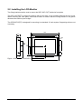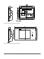
1
High Resolution 31 cm/12" LCD-Monitor SCD 1297 Operating Instructions SCD 1297-C/CT (1) (Chassis) 6GF6240-3MA (-3MB with Touch) SCD 1297-E/ET/ETH/ETC/ETB (1) (Mountable) 6GF6240-4MA (-4MB with Touch) 6GF6244-4MB/ 6GF6240-4MC/6GF6242-4MB SCD 1297-R/RT (1)(Rack 19") 6AV8100-0CA00.0AA1/6AV8100-0CB00-0AA1) 6GF6240-6MA01 (-6MB01 with Touch) Copyright Siemens AG LCD-Monitor SCD1297 Page 1 / 19 DOC-No.: B3 0071D1.DOC No part of this document may be reproduced or transmitted without express permission. Violations will result in prosecution. All rights reserved. 2001 All rights reserved 이 기기는 업무용(A급) 전자파 적합기기로서 판매자 또는 사용자는 이 점을 주의하시기 바라며 가정 외의 지역에서 사용하는 것을 목적으로 합니다. LCD-Monitor SCD1297 Page 2 / 19 DOC-No.: B3 0071D1.DOC Contents 1 Overview ..................................................................................................................................... 4 1.1 Layout of this Handbook ...................................................................................................... 5 1.2 Warnings and Safety Notes ................................................................................................. 6 1.2.1 Instructions for Handling Assemblies Susceptible to Electrostatic Shock ..................... 7 2 General Installation ..................................................................................................................... 7 2.1 Removing the Packaging and Checking Individual Parts ..................................................... 7 2.2 Installing the LCD-Monitor ................................................................................................... 8 2.2.1 Installation of the AC/DC-power supply unit or 24V-DC/DC-Converter....................... 10 2.3 Cable Connections and Pin Assignments .......................................................................... 10 2.4 Electrical Installation .......................................................................................................... 12 2.5 Touch-screen version SCD 1297xx/T ................................................................................ 12 3 Operation and Alignment........................................................................................................... 13 3.1 Location of the Operation and Alignment Controls............................................................. 13 3.2 Using and Adjusting the Converter .................................................................................... 14 3.2.1 OSD-Menu................................................................................................................. 14 3.2.2. Quick-OSD-Menu-Functions ...................................................................................... 15 3.2.3. OSD-Menu-Function .................................................................................................. 16 4 Technical Data .......................................................................................................................... 18 4.1 Display Module .................................................................................................................. 18 4.2 Power Supply .................................................................................................................... 18 4.3 Operating Conditions ......................................................................................................... 18 4.4 Protection .......................................................................................................................... 18 4.5 Enclosure .......................................................................................................................... 19 4.6 Input Signals...................................................................................................................... 19 4.7 EU Declaration of Conformity on EMC............................................................................... 19 Figures Figure 1: Dimensions of the SCD 1297-C/CT...................................................................................... 8 Figure 2: Dimensions of the SCD 1297-E/ET ...................................................................................... 9 Figure 3: Dimensions of the SCD 1297-R/RT...................................................................................... 9 Figure 4: VGA Interface..................................................................................................................... 11 Figure 5: Location of the operation and alignment controls ............................................................... 13 LCD-Monitor SCD1297 Page 3 / 19 DOC-No.: B3 0071D1.DOC 1 Overview The LCD monitor SCD 1297 has been developed and constructed especially for industrial applications. This monitor can be used in applications where a standard CRT-device would be unsuitable, due to space or environmental restrictions. Its compact enclosure opens up a wide spectrum of possible application areas for the SCD 1297, ranging from air-conditioned computer rooms behind a switching cabinet door, to the immediate vicinity of machinery in a special protective enclosure. As is the case for all industrial systems, the monitor has been designed to withstand the particular demands placed upon such equipment, e.g., it is immune to electromagnetic radiation and can withstand a large temperature range. The trend-setting LCD technology in this monitor has relegated picture geometry distortion and colour patches to the past. Even at the low refresh rate of 50 Hz. the screen remains flicker-free. The SCD 1297 thus fulfils even the strictest ergonomic requirements. Pictures of lower resolution are expanded to fill the screen. The SCD 1297 can simultaneously display up to 262144 colours enabling realistic colour images and videos to be displayed. The LCD-monitor contains special hardware to convert a standard analogue VGA video signal for the display controller. Compatibility with conventional CRT monitors is, thus, guaranteed. It is very easy to adjust the monitor settings using the clearly designed OSD (On Screen Display). The “Automatic Alignment” function does away with the need to carry out tedious adjustments such as picture position and phase. At the press of a button, the monitor performs these alignments automatically. The SCD 1297 is equipped with an active 12.1” TFT display module with a maximum resolution of 800x600 pixels. The integrated power management system VESA DPMS, allows a significant reduction in power consumption when the synchronisation signal from the computer has been switched off, compared with that under “normal” operation. Three versions of the monitor are available: stand-alone chassis mountable with front plate 19“ rack 6 HE LCD-Monitor SCD1297 SCD1297-C(CT with Touch) SCD1297-E (ET with Touch) SCD1297-R(RT with Touch) Page 4 / 19 DOC-No.: B3 0071D1.DOC 1.1 Layout of this Handbook This handbook should be kept within reach while installing and operating the LCD-monitor. It has been laid out so that even inexperienced users can find the information they require. Chapters are clearly arranged according to subject. In detail, the chapters are arranged as follows: • Chapter 1 Introduction This chapter provides a brief description of the SCD 1297, including its properties, application areas and special features. • Chapter 2 Installation This chapter is mainly concerned with preparing the LCD-monitor for use, its installation and cabling. • Chapter 3 Operation All operations and adjustment possibilities for the SCD 1297 are described here • Chapter 4 Technical Data This chapter contains technical details such as dimensions, power supply, environmental considerations and EMC data. Important: The manufacturer has gone to great lengths to match the quality of the documentation to the high standard of this product. In achieving this, we are reliant on the support of our customers. If anything in this handbook is not clearly understandable or if there are any errors, then please submit a short note to that effect. The same applies for any suggestions for improvement. We are grateful for all such assistance. LCD-Monitor SCD1297 Page 5 / 19 DOC-No.: B3 0071D1.DOC 1.2 Warnings and Safety Notes Transport The LCD-monitor should only be transported in its original packaging to ensure it will be protected against shocks and rough handling. Setting up When installing the monitor, it should be noted whether any moisture (condensation) has entered the unit during transport or storage. Additional important installation information can be found in the “Technical Data” chapter. EMC This is a Class A piece of equipment (industrial use). In domestic situations, it may cause interference. Under such circumstances, the operator can be required to undertake appropriate measures to minimise problems . This LCD-monitor is a component designed for building into industrial systems. The operator of the entire plant is responsible for maintaining electromagnetic compatibility according to EMC-law. Repairs Before the unit is opened, the supply voltage must be switched off. Only authorised persons may open the unit. Additions or changes to the unit may damage the system or affect its EMC behaviour. Cleaning The unit must be isolated from the power supply before cleaning. If heavily soiled, the LCD-monitor can be cleaned with a damp cloth and mild detergent. Care must be taken to ensure that no moisture enters the unit during cleaning. Scouring powders and solvents must never be allowed to come in contact with the unit. The inside of the unit is to be cleaned by qualified service technicians only. LCD-Monitor SCD1297 Page 6 / 19 DOC-No.: B3 0071D1.DOC 1.2.1 Instructions for Handling Electrostatic Shock Assemblies Susceptible to Most of the assemblies within the SCD 1297 LCD-monitor contain components which can be destroyed by electrostatic voltages. It is also possible for the assemblies to be damaged in such a way that total failure does not occur. If you (as an authorised service technician) are handling such assemblies then the following precautions should be observed: When such assemblies are being handled, a means of electrostatic discharge must be available. This can be, for example, an earthed object, which can be touched to discharge electrostatic voltages. This applies to all tools used (insulated). They must also be discharged at an earthed object. When assemblies are removed or added to the system, the unit must always be switched off and the power supply cable disconnected. Vulnerable assemblies should always be held by their edge. Avoid touching tracks and contact pins. 2 General Installation Preparation for installing the LCD-monitor include the following points: Removal of all packaging Checking of components for damage Comparison of components received with those on the delivery note Connection to the computer system and power supply Building into your system, bearing in mind technical and ergonomic aspects 2.1 Removing the Packaging and Checking Individual Parts After unpacking all the delivered components, they should be checked for completeness and for possible transport damage (visual inspection). If any deficiencies are found then please contact the service department given on the delivery note. Have the delivery note number, serial number and a description of the deficiency to hand. The original packaging should be kept for future transportation. LCD-Monitor SCD1297 Page 7 / 19 DOC-No.: B3 0071D1.DOC 2.2 Installing the LCD-Monitor Two fixing brackets can be used to mount the SCD 1297-C(CT) behind a front plate. The SCD 1297-E(ET) is delivered together with a front plate. It has a sealing band all the way round. When mounting the front plate, care must be taken to ensure that the O-ring remains in its groove otherwise the seal may not be tight. The SCD1297-R(RT) is designed for mounting in a standard 19“ rack system. Supporting rails are not necessary. 329 307 40 5x20 ACTIVE AREA 246x184.5 41 111 147 229 A 76 154.5 Figure 1: Dimensions of the SCD 1297-C/CT LCD-Monitor SCD1297 319 Page 8 / 19 DOC-No.: B3 0071D1.DOC 40 M3x10 A 76 4 Figure 2: Dimensions of the SCD 1297-E/ET 483 465 40 SIEMENS A ACTIVE AREA 246x184.5 + - 265.9 190.4 ON 76 4 Figure 3: Dimensions of the SCD 1297-R/RT LCD-Monitor SCD1297 Page 9 / 19 DOC-No.: B3 0071D1.DOC Thermal Problems In order that the LCD-monitor maintains an optimum operating temperature while in use, air must be allowed to circulate freely around the SCD 1297 enclosure. It is particularly important that the rear of the system is kept free. Please bear in mind that increased temperatures can lead to defects and to a significant reduction in the lifetime of the monitor. EMC Problems This LCD-monitor is a piece of equipment designed for building into an industrial system. The operator of the entire plant is responsible for maintaining electromagnetic compatibility according to EMC laws. Safety Problems All voltage and signal connections must adhere to appropriate legal requirements. Ergonomics The screen should be easily viewable from all sides and without reflections. 2.2.1 Installation of the AC/DC-power supply unit or 24V-DC/DCConverter Either an AC/DC power supply unit or a DC/DC converter can be used to supply the control panel with 24DC. If an AC/DC power supply unit is used, it is attached to the enclosure using the bracket indicated in Fig. 1 on page 10. If the DC/DC converter, which is delivered with the unit, is to be used then it should be inserted below the AC/DC power supply unit shown in Fig. 1, so that the 24V connector is accessible. The DC/DC converter should then be screwed to the enclosure using to the two holes provided for the bracket. The cable from the AC/DC power supply unit (12VDC) or from the DC/DC convertr is plugged directly into the socket (power) on the SCD 1297-K. It should be secured using a pul-relief. Einschieben des DC/DC-Wandlers unter den Deckel Befestigungslöcher für DC/DC-Wandler 2.3 Cable Connections and Pin Assignments The LCD-monitor has been tested and set-up in the factory. Before use, the power supply and the VGA signals should be connected to the sockets provided. Connections to the monitor should adhere to EMC regulations. LCD-Monitor SCD1297 Page 10 / 19 DOC-No.: B3 0071D1.DOC A high-quality 75-ohm coaxial cable must be used for the VGA-signals. Low quality cables can result in interference and shadowing on the display. VGA-Interface The VGA interface is a standard 15-pin male HD-D-type connector. Figure 4: VGA Interface Pin 1 2 3 4 5 6 7 8 9 10 11 12 13 14 15 Signal Video input RED Video input GREEN Video input BLUE Not used Not used GND (RED) GND (GREEN) GND (BLUE) Not used GND Not used Not used H-Sync. V-Sync. Not used LCD-Monitor SCD1297 Page 11 / 19 DOC-No.: B3 0071D1.DOC Power Supply Power is supplied to the SCD 1297 via a standard power connector on the rear of the unit. Pin O Name GND +12V Description Power supply ground GND Power supply +12VDC 2.4 Electrical Installation Before connecting the SCD 1297 to the power supply, a check should be carried out as to whether the VGA connector is plugged in properly and that the screws are tightened. There is a compartment on the rear of the unit to hold the standard power supply unit delivered with the display. The monitor can, however, also be powered by a 12 V supply (observe polarity of the power supply connections). If a video signal is connected, the image will appear immediately on the screen. There are many possible reasons why an image might fail to appear on the display after it has been switched on: - no VGA signal connected - no synchronisation signal connected - horizontal and vertical synchronisation signals are connected the wrong way round 2.5 Touch-screen version SCD 1297xx/T The installation of the necessary touch screen driver software is described in the manufacturers original touch-screen manual which is enclosed. LCD-Monitor SCD1297 Page 12 / 19 DOC-No.: B3 0071D1.DOC 3 Operation and Alignment This chapter contains a description of all the operating and alignment functions. 3.1 Location of the Operation and Alignment Controls All the controls are accessible from the rear of the unit. Their exact position in shown in Figure 1 on page 32. These controls are used for navigating in the OSD menu and for selecting and altering parameters. S1 S2 S3 S4 Power supply VGA-interface Touchscreen (option) and service connector Figure 5: Location of the operation and alignment controls S1 S2 S3 S4 LCD-Monitor SCD1297 + Menu Set Page 13 / 19 DOC-No.: B3 0071D1.DOC 3.2 Using and Adjusting the Converter Since there are no standards for video output signals from VGA cards, the first time the unit is switched on it will automatically adjust itself to the graphic card currently being used. 3.2.1 OSD-Menu The „On Screen Display“ OSD is a menu system, which is shown on the display. With the help of OSD and the described controls elements, all adjustments of the monitor are executable. There are just 4 keys S1 to S4 to control the OSD. OSD-Menu / Quick-OSD-Menu In addition to the OSD menu there are more possibilities to adjust important functions like brightness, contrast and automatic adjustment directly via a Quick-OSD-menu. Function(s) of the control keys: <+> Increase value, menu navigation (go to sub menu / go to right) Invoke Quick-OSD-menu: To execute an automatic adjustment <-> Decrease value, menu navigation (go to left) MENU Invoke OSD Menu navigation (switching between main- and sub-menu) SET Menu navigation (go down) Invoke Quick-OSD-menu: Brightness and contrast adjustment LCD-Monitor SCD1297 Page 14 / 19 DOC-No.: B3 0071D1.DOC 3.2.2. Quick-OSD-Menu-Functions Following adjustments can do via the Quick-OSD-menu: Brightnes Contrast Auto adjust Invoke via key <SET> Function Contrast Brightness Adjustment/value Range: 0 to 100 via key <+>/<-> Range: 0 to 100 via key <+>/<-> Description Contrast adjustment Brightness adjustment Invoke via key <+> Function Adjustment/value Description Automatic image adjustment Press key <+> to start the adjustment Perform an automatic image adjustment. Adjustment of frequency, phase and image position. LCD-Monitor SCD1297 Page 15 / 19 DOC-No.: B3 0071D1.DOC 3.2.3. OSD-Menu-Function Invoke via key <MENUE> Main menu Function Adjust function / value / range Description Picture 1 Brightness setting range: 0 to 100 through key (+/-) adjust brightness Contrast setting range: 0 to 100 through key (+/-) adjust contrast change contrast between dark and light colors H Position setting range: 0 to 100 through key (+/-) move picture in horizontal direction V-Position setting range : 0 to 100 through key (+/-) move picture in vertical direction Phase setting range : 0 to 31 through key (+/-) adjust phase of input signal Frequency setting range : 950 to 1050 (dependent to picture) through key (+/-) adjust frequency of input signal Sharpness 1, 2, 3, 4, 5 adjust sharpness of the picture by using no. 1 to 5 1=sharp, 5= soft Gamma Linear or CRT correction of gamma curve value of colors will be forwarded to the display Color temperature 5000 - 6500 – 9300 - VAR color temperature / adjust color three defined and one adjustable color temperatures are for selection activate „VAR“ - for RGB shows up a adjustment beam. 0 to 100 % (50% correspond to factor 1) Picture 2 Option 1 OSD select between nine defined OSD positions f define position OSD OSD H-Position setting range : 0 to 100 through key (+/-) move OSD-menu in horizontal position OSD V-Position setting range : 0 to 100 through key (+/-) move OSD-menu in vertical position OSD timeout 5 ... 60 seconds adjust time after the OSD menu is automatically fade out the adjustment ensures between 5 to 60 s in steps of5 s. OSD background Opaque – Transparent select background color of the OSD menu you have the choice between transparent and colored background. Backlight setting range : 0 to 100 through key (+/-) adjust brightness ob backlight display herewith you can match the brightness of the picture with the brightness of the room. Noise suppression ON - OFF Standard adjustment OFF. By ON: Activate the function noise suppression. This function suppresses interference at the sync signal lines to avoid A new auto adjustment during short interference. LCD-Monitor SCD1297 Page 16 / 19 DOC-No.: B3 0071D1.DOC Main menu Function Adjust function / value / range Description Option 2 DPMS ON – OFF Display Power Management System (DPMS) on or off If DMPS activated, the monitor is turn off (backlight) when a synch signal is left. The screen is dark. Source scan OFF – ON – Standard Standard: ON Note: To scan new video source is not relevant because the monitor has one RGB input source only. Blank color red – reen – blue – black Choose the background color of the screen when no input signal is present. Display – Display resolution (not from the input source) Info signal source ON – OFF Input source icon on or off The icon is shown when input signal are changed. The icon shows the following information’s: signal source (e.g. RGB analog) Mode number (internal mode number of the timing list) Image resolution of the input signal H- and V-frequency Language Englisch – German Calibration <+> press OSD language Adjustment of the internal A/D converter (following the menu instruction) Factory reset <+> press Reset of values like brightness, contrast,.. to default values Installation RGBMode <+> press Enter a new timing which is not in the internal timing table. This function should used, when the shown image resolution is not the resolution are expect. When press <+> the sub menu expect 9 timing parameter. – Show the H- and V-Frequency of the present input signal. H/V-total, H/V-start – Show the used timing parameter of the present input signal Option Var. RGB-Mode inactive, Mode1, Mode2, Mode3 Inaktiv: used the internal timing table only Mode1: use the timing parameter and perform a complete auto adjustment. (usually used) Mode2: use the timing parameter and perform an auto adjustment without an automatic image position adjustment. Mode3: use the timing parameter and perform an auto adjustment without an automatic frequency adjustment. H-resolution 100 to 2000 through key (+/-) Horizontal image resolution (important parameter) V-resolution 100 to 2000 through key (+/-) Vertical image resolution (important parameter) H-total 100 to 2500 through key (+/-) Whole pixel per line (important parameter) H-Start 0 to 750 through key (+/-) Number of Pixels from H-sync start to image start V-Start 0 to 500 through key (+/-) Number of lines from V-sync start to image start Install Utilities When <+>, H- and VFrequency Info <+> press Activate the feed timing parameter test pattern <+> press Show a test image Firmware, Resolution, Timing – Show the firmware version and timing data of the present input signal LCD-Monitor SCD1297 Page 17 / 19 DOC-No.: B3 0071D1.DOC 4 Technical Data 4.1 Display Module Type Diagonal Display area (WxH) Resolution Pitch Colours Backlight Brightness (typical) Colour active TFT-LCD 30.8 cm (12.1") 246 x 184.5 mm² 800 x 600 pixels 0.33 x 0.33 mm² 262144 2xCCFT (Cold Cathode Fluorescent Tube) approx. 250 cd/m² 4.2 Power Supply Input voltage Power consumption (normal operation) Power consumption (StandBy) 11.4 – 12.6 VDC approx. 18 W approx. 5 W 4.3 Operating Conditions Operating temperature Storage temperature Humidity +5 to +45°C -20 to +60°C max. 95% (non condensing) 4.4 Protection Protection Class Front screen in E(ET) and R(RT) LCD-Monitor SCD1297 IP20 IP65 Page 18 / 19 DOC-No.: B3 0071D1.DOC 4.5 Enclosure Weight Enclosure material Enclosure colour approx. 3.2 kg steel light basic 4.6 Input Signals Level (Video) Bandwidth Impedance Synchronisation 0.7Vss RGB analogue at 75Ω 140Mhz (-3dB) 75Ω Sep. Sync. (TTL) Sync on green Composite Sync 30 to 97 kHz 50 to 100 Hz** H-Frequency V-Frequency 4.7 EU Declaration of Conformity on EMC Product LCD-Monitor SCD 1297 Test foundations EU framework guidelines Harmonised used standards EN 55022 +A1/EN55022/A1 EN 50082-2 EN 60950 LCD-Monitor SCD1297 No. 89/336/EWG No. 92/031/EWG No. 73/23/EWG No. 93/68/EWG Edition 05/1995 Edition 08/1994 Edition 02/1996 Interference emissions Edition 11/1997 Safety Page 19 / 19 Interference resistance DOC-No.: B3 0071D1.DOC