1
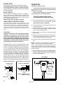
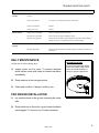
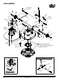
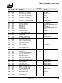
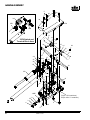
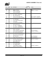
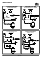
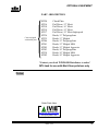
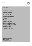
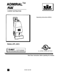
MERIT
FLOOR POLISHER
TM
Owner’s Guide
Contents:
1
Warnings - Product Description
2
Operation / Maintenance / Service
3
Troubleshooting
4
Main Assembly
6
Handle Assembly
8
Wiring Diagrams
9
Optional Equipment & Notes
Order Parts Here:
www.ivie-ent.com/parts
Ph:(918)254-5161
WARNING OF
POTENTIAL INJURY:
10 Warranty
This product contains moving parts. To
reduce the risk of injury unplug the
machine before servicing.
Whenever repairs are made ensure electrical
connections are correct and wiring matches
APPROPRIATE diagram before plugging
machine into an electrical outlet.
CAUTION:
Record model and serial number located on data label.
Refer to these numbers when calling Windsor dealer for
parts or service.
MODEL :
SERIAL NO. :
PURCHASE DATE :
1.)
See the Owner’s Guide for
complete operating instructions.
2.)
Maintenance and repairs must onlybe done
by qualified personnel.
3.)
Using non-Windsor parts to repair this
machine will void the warranty.
REV.
A
98295 7/1/97
INDUSTRIES, INC., 1351 W. Stanford Ave., Englewood CO 80110 USA *303-762-1800*FAX
303-762-0817
INSPECTION
OPERATION
Please carefully unpack and inspect your machine
for shipping damage. Each unit is operated and thoroughly inspected before shipment, and any damage is
the responsibility of the delivering carrier who should be
notified immediately.
CAUTION: For Indoor Use Only.
To prevent possible damage to the floor when using
the Brush option, use water or other approved cleaning
solution while operating.
When using the pad optioin, always keep the machine moving when in contact with the floor.
ELECTRICAL
This rotary polisher is designed to operate on a standard 15
amp, 115 volt, 60 hz, AC household current. Check that the
voltage shown on the serial number plate is suitable for the
supply available. Voltages below 105 volts or above 125 volts
could cause damage to the motor.
NOTE: 230/250 volt 50 hz models are available.
WARNING:HIGH STARTING TORQUE.
HOLD MACHINE FIRMLY WITH BOTH HANDS.
1.)
GROUNDING INSTRUCTIONS
This appliance must be grounded. If it should malfunction or break
down, grounding provides a path of least resistance for electric current
to reduce the risk of electric shock. This appliance is equipped with a
cord having an equipment-grounding conductor and grounding plug.
The plug must be inserted into an appropriate outlet that is properly
installed and grounded in accordance with all local codes and ordinances.
2.)
Plug the machine into a wall outlet as described in the
grounding instructions.
3.) Lower the handle by unlocking the adjustment handle
and moving the handle into position. Relock the handle
when it is in a comfortable position.
WARNING:
4.) Check to be sure the pad driver or brush is installed
before starting.
Improper connection of the equipment-grounding
conductor can result in a risk of electric shock.
Check with a qualified electrician or service person
if you are in doubt as to whether the outlet is properly grounded. Do not modify the plug provided with
the appliance - if it will not fit the outlet, have a proper
outlet installed by a qualified electrician.
5.) With the switch lock(s) rotated forward, squeeze one of
the switch levers, turning the machine on. (These levers
can be operated independently of each other)
6.) To stop the machine, release the switch lever and switch
lock.
NOTE: The machine is equipped with a circuit breaker to
protect the motor in the event an overload condition
occurs. The circuit breaker is located at the bottom of the
switch housing. Push the reset button to restart the machine.
If the breaker trips again, correct the cause of overloading
before proceeding.
This appliance is for use on a nominal 120-volt circuit,
and has a grounded plug that looks like the plug in “Fig.
A” below. A temporary adaptor that looks like the adaptor
in “Fig . C” below may be used to connect this plug to a
2-pole receptacle as shown in “Fig. B” below, if a properly
grounded outlet is not available. The temporary adaptor
should be used only until a properly grounded outlet (Fig.
A) can be installed by a qualified electrician. The green
colored rigid ear, lug, or the like extending from the
adaptor must be connected to a permanent ground such
as a properly grounded outlet box cover. Whenever the
adaptor is used, it must be held in place by a metal screw.
7.) Do not let machine rest on pad. When finished with the
machine for the day return handle to the storage position.
Be sure to leave machine in a safe place where there
is no risk of being tipped over.
CONTROLS
Switch Locks
PROPER GROUNDING
GROUNDING CONNECTION
CONNECTION
USING AN ADAPTOR
Grounding Pin
Grounded
Outlet
Ensure that the pad driver or brush is installed correctly
and in good shape. Install or change pad if necessary
(See Page 3 for detail of installation).
Switch Lever
Metal Screw
Solution Lever
(For optional
Solution Tank)
Adaptor
Fig. A
Tab For Grounding
Screw
Grounded Outlet Box
Fig. B
NOTE: Adaptors are not
allowed in Canada.
ADAPTOR
Fig. C
2
Switch Lever
98295 7/1/97
Circuit Breaker
TROUBLE SHOOTING CHART
PROBLEM
No power to
machine
Electrical shock
Circuit breaker
tripping
POSSIBLE CAUSE
SOLUTION
Dead electrical circuit breaker or
fuse box.
Check building circuit
Power switch failure
Test switch for continuity and replace if necessary.
Faulty circuit breaker
Replace.
Faulty power cord
Replace.
Equipment not grounding
Follow grounding instructions exactly.
Receptacle not grounded
Have an electrician inspect building’s wiring.
Internal wiring problem
Ensure that the machines wiring matches the appropriate wiring diagram.
Replace any wires or components which are short circuiting
Faulty circuit breaker
Test circuit breaker for continuity. Replace circuit breaker if necessary.
Mechanical problem
Higher amp draws indicate a mechanical problem, find the parts which are
not moving
DAILY MAINTENANCE:
PAD INSTALLATION:
(At the end of each working day):
1.) Inspect power cord for wear. To prevent electrical
shock replace cords with frayed or cracked insulation
immediately.
Ensure Pad is Centered on Pad
Driver. Pull Pad to edge of Pad
Driver in several directions to
check for proper engagement.
2.) Place machine in the storage position.
3.) Check pad condition. Change if soiled or torn.
PAD DRIVER INSTALLATION:
1.) Lay machine back on the ground, exposing the under
side.
2.) Place pad driver on the motor lug and rotate clockwise
until engaged. To remove, turn Counter-clockwise.
98295 7/1/97
3
MAIN ASSEMBLY
16 See asm.
below
A
8
9
7
32
10
31
17
5(3)
4AB
18
33(2)
19(2)
12
38
39
11
35 15
8
22
23
6AB
1ABCE
FGHK
13ABC
20
14
2ABC
9
8
20 21 8
10
7
3ABC
Optional Pad Driver shown.
See Page 9 ”Optional Equipment”
for additional options.
24(4)
25(4)
6C
5(3)
26
Adjustment Handle Asm (38268)
6D
36A
38
51237
27
4C
57018
37
34(2)
28
30
29
1DJ
67342
Motor Assembly
(2 Speed Only)
4
70478
98295 7/1/97
MAIN ASSEMBLY Parts List
Ref
Part No.
Qty
1A
1B
1C
1D
1E
1F
1G
1H
1J
1K
2A
2B
2C
3A
3B
3C
4A
4B
4C
5
6A
6B
6C
6D
7
8
9
10
11
12
13A
13B
13C
14
15
16
17
18
19
20
21
22
23
24
25
26
27
28
29
30
31
32
33
34
35
36A
36B
37
38
39
53219
53220
53218
53226
53221
53222
53223
53224
53227
53225
14992
14608
14561
20081
20071
20070
27603
27602
27608
70351
50673
50674
50675
50681
57196
87146
89086
87140
03079
73779
34246
34245
34244
73780
57021
38268
87148
41270
70384
87003
57119
27682
70461
87067
70305
72144
27376
73696
73697
27606
73195
23180
87025
70351
87021
51116
51118
87101
50688
50776
1
1
1
1
1
1
1
1
1
1
1
1
1
1
1
1
1
1
1
3
1
1
1
1
2
6
2
2
1
2
1
1
1
1
1
1
1
1
2
2
1
1
1
4
4
1
1
1
1
1
1
1
2
2
1
1
1
1
1
1
Serial No.
Description
From
Motor, 115V 1/3 HP (175 RPM)
Motor, 115V 1 HP (175 RPM)
Motor, 115V 1.5 HP 175 RPM)
Motor, 115V 1.5 HP (175/300 RPM)
Motor, 115V 1.5 HP (300 RPM)
Motor, 220V 1/3 HP (175 RPM)
Motor, 220V 1 HP (175 RPM)
Motor, 230V 1.5 HP (175 RPM)
Motor, 240V 1.5 HP (175/300 RPM)
Motor, 230V 1.5 HP (300 RPM)
Bumper, 13” dia shroud
Bumper, 17” dia shroud
Bumper, 20” dia shroud
Clamp, Merit 13”
Clamp, Merit 17”
Clamp, Merit 20”
Cover, small motor
Cover, large motor
Cover, 2 speed motor
Scr, 10-32 x 3/8 HHTR w/star
Label, Merit 175
Label, Merit 300
Label, Merit 175/300 large
Label, Merit 175/300 small
Nut, 1/2 push-on dome cap
Washer, 1/2”ID x 1”OD x .06” nylon
Wheel, 5”OD x .5”ID x 1” grey
Washer, 1/2”ID x 3/4”OD wave
Axle, 1/2” dia x 13.615” CRS PLTD
Support, Merit handle RT
Frame, 13” polisher
Frame, 17” polisher
Frame, 20” polisher
Support, Merit handle LT
Nut, 1/2-20 Ny-loc
Handle asm, adjustment
Washer, 3/8”ID x .88”OD x .19” flat
Hook, Merit cord
Scr, 1/4-20 x 1/2 PHTR BLK PLT
Washer, 3/8”ID x 7/8”OD SS
Nut, 3/8-16 lock PLTD
Clamp, Merit handle lock
Scr, 3/8-16 x 3.5” HHCS GR5
Washer, 5/16 int star lock PLT
Scr, 5/16-18 x 3/4 HHCS GR5
Switch, 125V SPST Rockr w/Boot
Clip, switch retainer
Screen, upper motor
Screen, lower motor
Cover, 2sp polisher switch
Strain relief, 1/2 NPT
Cord set, 14/3 SJTW x 45” Blk
Washer, 1/4 lock ext. star SS
Scr, 10-32 x 3/8 HHTR w/star
Washer, 1/2 int. star lock
Light, 115V Brush Wear
Light, 230V Brush Wear
WASHER, 1/2 ID Spring
Label, Windsor logo
Label, Warning for Safety
98295 7/1/97
To
Notes:
M13
M17,M20
M20X, M17X
MDS20
M320
M13I
M17I,M20I
M20XI
MDS20I,MDS17I
M320I
M13
M17,MDS17I
M20,M20X,MDS20,M320, M17X
M13
M17,MDS17I
M20,M20X,MDS20,M320, M17X
M13
M17,M20,M20X,M320, M17X
MDS20
M13,M17,M20,M20X, M17X
M320
MDS20,MDS17I
MDS20,MDS17I
M13
M17,MDS17I
M20,M20X,MDS20,M320, M17X
See inset on p.4 for assembly.
MDS20,MDS17I
MDS20,MDS17I
MDS20,MDS17I
MDS20,MDS17I
MDS20,MDS17I
MDS20,MDS17I
MDS20
MDS17I
MDS20,MDS17I
5
HANDLE ASSEMBLY
5
16
36
34
36
7A
27B
20B
11
13
230V Switch and
Terminal Block Asm
14
15
33
15
14
24
12
32
11
10
24
23
20A
21
33
17
29
26
9
25
10
22
27A
19
9
30
31
8
28
18
1ABC
35
A
7A (On 115V machines)
7B (On 230V ”I” machines)
2
3
6
4
5
5
6
98295 7/1/97
HANDLE ASSEMBLY Parts List
Ref
Part No.
Qty
1A
1B
1C
2
3
4
5
6
7A
7B
8
9
10
11
12
13
14
15
16
17
18
19
20A
20B
21
22
23
24
25
26
27A
27B
28
29
30
31
32
33
34
35
36
14700
14668
14312
27558
50649
14942
70384
57006
41234
41246
51188
66187
51187
36139
51192
51191
73571
70242
70451
70455
73400
73402
72123
72119
70351
20054
70335
87016
57003
99627
23167
23169
78288
73572
62251
62344
78270
66199
76112
87067
87025
1
1
1
1
1
1
4
2
2
1
1
3
2
2
1
1
2
2
2
2
1
1
1
1
1
1
1
1
1
1
1
1
1
1
1
1
1
2
1
1
2
Serial No.
Description
From
Breaker 15A 250VAC 50VDC
Breaker, 8A Circuit
Breaker, 7A Circuit
Collar, Circuit Breaker
Label, Circuit Breaker
Boot, 3/8 circuit breaker
Scr, 1/4-20 x 1/2 PHTR Pltd.
Nut, 1/4-20 Hex Pltd
Housing, POL Handle (Logo)
Housing, POL Handle Rear Mach’d
Lever, Height Polisher Handle
Pin, POL Handle
Lever, Switch Polisher Handle
Grip, Handle
Lock, Switch Lt. POL Handle
Lock, Switch Rt. POL Handle
Spring, Handle Lock
Scr, 4-40 x 1/4 PHMS Pltd.
Scr, 1/4-20 x 1.62 SHCS Pltd
Scr, #6-32 x 1.00 PPHTF Pltd.
Spacer, UL Switch
Spacer, Adj. Handle
Switch, 25A SPST 125-250V Snap
Switch, Snap POL Handle 230V
Scr, 10-32 x 3/8 HHTR w/Star
Clamp, 3/8 Nylon UL/CSA
Scr, 10-32 x 1/2 PHTR Grn/Grnd
Washer, #10 Lock Ext Star SS
Nut, Yellow Wire
Electric Tape, 3/4 w/UL-CSA
Cord Set, 14/3 Std x 50’ Yellow
Cord Set, 1.5mm Euro x 50’ Blk
Tube, Polisher Handle Merit
Spring, Switch Handle
Plate, Handle Lever
Plate, Lever Plug
Tube, Handle Polisher
Pin, Polisher Handle
Terminal Block, 3 position
Washer, 5/16 lock int star plt.
Washer, 1/4 lock ext star
98295 7/1/97
To
Notes:
M17,M20,M20X,MDS20,M320 M17X
M13
All 230V ”I” machines.
Qty.1 on 230V ”I” machines.
Used on 230V ”I” machines only.
Installed for optional Sol. tank.
Used on 115V machines only.
All 115V machines.
All 230V ”I” machines.
All 115V machines.
All 115V machines.
All 115V machines.
All 230V ”I” machines.
All 230V ”I” machines.
7
WIRING DIAGRAMS
115V Diagram Single Speed
230V Diagram Single Speed
(All models except MDS20)
(All models except MDS17I, MDS20I)
115V Diagram Dual Speed
230V Diagram Dual Speed
(MDS20 only)
8
(MDS17I, MDS20I)
98295 7/1/97
OPTIONAL EQUIPMENT
PART #DESCRIPTION
Come equipped
with clutch plate
02220
02216
02218
02219
02217
02236
02235
02206
02241
02205
02203
02238
02202
Clutch Plate
Pad Driver, 12” Merit
Pad Driver, 16” Merit
Pad Driver, 19” Merit
Pad Driver, 19” Merit high speed
Brush, 11” Polypropylene
Brush, 11” Malgrit
Brush, 15” Polypropylene
Brush, 15” Malgrit Mild
Brush, 15” Malgrit Aggresive
Brush, 18” Polypropylene
Brush, 18” Malgrit Mild
Brush, 18” Malgrit Aggresive
*Contact your local WINDSOR Distributor to order*
MT4 tank for use with Merit floor polishers only
Notes:
Order Parts Here:
www.ivie-ent.com/parts
Ph:(918)254-5161
98295 7/1/97
9