1
SIMATIC Industrial PC SIMATIC Industrial PC SIMATIC Panel PC 677B
SIMATIC
Industrial PC
SIMATIC Panel PC 677B
Operating Instructions
1
Preface
______________
2
Safety
______________
3
Description
______________
4
Application planning
______________
5
Mounting
______________
6
Connecting
______________
Integration into an
7
______________
automation system
8
Commissioning
______________
9
Operation and configuration
______________
10
Operation
______________
11
Functions
______________
12
Maintenance and service
______________
Alarm, error, and system
13
messages
______________
05/2007
A5E01035609-01
14
______________
15
Specifications
______________
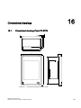
16
Dimensional drawings
______________
17
Detailed descriptions
______________
A
Appendix
______________
List of
B
Abbreviations/Acronyms
______________
Troubleshooting/FAQs
Safety Guidelines
Safety Guidelines
This manual contains notices you have to observe in order to ensure your personal safety, as well as to prevent
damage to property. The notices referring to your personal safety are highlighted in the manual by a safety alert
symbol, notices referring only to property damage have no safety alert symbol. These notices shown below are
graded according to the degree of danger.
Danger
indicates that death or severe personal injury will result if proper precautions are not taken.
Warning
indicates that death or severe personal injury may result if proper precautions are not taken.
Caution
with a safety alert symbol, indicates that minor personal injury can result if proper precautions are not taken.
Caution
without a safety alert symbol, indicates that property damage can result if proper precautions are not taken.
Notice
indicates that an unintended result or situation can occur if the corresponding information is not taken into
account.
If more than one degree of danger is present, the warning notice representing the highest degree of danger will
be used. A notice warning of injury to persons with a safety alert symbol may also include a warning relating to
property damage.
Qualified Personnel
The device/system may only be set up and used in conjunction with this documentation. Commissioning and
operation of a device/system may only be performed by qualified personnel. Within the context of the safety notes
in this documentation qualified persons are defined as persons who are authorized to commission, ground and
label devices, systems and circuits in accordance with established safety practices and standards.
Prescribed Usage
Note the following:
Warning
This device may only be used for the applications described in the catalog or the technical description and only
in connection with devices or components from other manufacturers which have been approved or
recommended by Siemens. Correct, reliable operation of the product requires proper transport, storage,
positioning and assembly as well as careful operation and maintenance.
Trademarks
All names identified by ® are registered trademarks of the Siemens AG. The remaining trademarks in this
publication may be trademarks whose use by third parties for their own purposes could violate the rights of the
owner.
Disclaimer of Liability
We have reviewed the contents of this publication to ensure consistency with the hardware and software
described. Since variance cannot be precluded entirely, we cannot guarantee full consistency. However, the
information in this publication is reviewed regularly and any necessary corrections are included in subsequent
editions.
Siemens AG
Automation and Drives
Postfach 48 48
90437 NÜRNBERG
GERMANY
A5E01035609-01
Ⓟ 03/2007
Copyright © Siemens AG 2007.
Technical data subject to change
Table of contents
1
Preface ...................................................................................................................................................... 7
2
Safety ........................................................................................................................................................ 9
3
4
5
6
7
2.1
Safety guidelines............................................................................................................................9
2.2
General Information .....................................................................................................................12
2.3
ESD directives..............................................................................................................................15
Description............................................................................................................................................... 17
3.1
Panel PC 677B design.................................................................................................................17
3.2
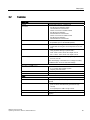
Features .......................................................................................................................................19
3.3
Panel PC 677B accessories ........................................................................................................21
Application planning................................................................................................................................. 23
4.1
Overview ......................................................................................................................................23
4.2
Unpacking and checking the delivery ..........................................................................................24
4.3
Device identification data .............................................................................................................25
4.4
4.4.1
4.4.2
4.4.3
4.4.4
Mounting positions and fastening ................................................................................................26
Installation guidelines...................................................................................................................26
Permitted mounting positions.......................................................................................................28
Type of fixation.............................................................................................................................28
Protection against dust and water ...............................................................................................29
4.5
4.5.1
4.5.2
Mounting cut-out ..........................................................................................................................30
Preparing the mounting cut-out....................................................................................................30
Mounting depth of the device.......................................................................................................32
4.6
EMC Guideline .............................................................................................................................33
Mounting.................................................................................................................................................. 35
5.1
Securing the device with clamps..................................................................................................35
5.2
Securing with screws ...................................................................................................................37
Connecting .............................................................................................................................................. 39
6.1
Connection elements and operator controls ................................................................................39
6.2
Connecting the 120 V / 240 V Ac power supply ..........................................................................41
6.3
Connecting the (24 V) DC power supply .....................................................................................44
6.4
Connecting the Equipotential Bonding Circuit .............................................................................45
6.5
Connecting Ethernet strain relief..................................................................................................46
6.6
Connecting the power plug locking mechanism ..........................................................................46
Integration into an automation system ..................................................................................................... 47
SIMATIC Panel PC 677B
Operating Instructions, 05/2007, A5E01035609-01
3
Table of contents
8
9
10
4
7.1
Overview ..................................................................................................................................... 47
7.2
7.2.1
7.2.2
Device in SIMATIC S7 network................................................................................................... 48
MPI/PROFIBUS-DP network....................................................................................................... 48
Connecting an S7 automation system ........................................................................................ 48
7.3
Transferring authorizations ......................................................................................................... 49
7.4
Networking via Industrial Ethernet .............................................................................................. 49
Commissioning ........................................................................................................................................ 51
8.1
Overview ..................................................................................................................................... 51
8.2
Switching on the device .............................................................................................................. 52
8.3
Setting up the Microsoft Windows operating system .................................................................. 53
8.4
8.4.1
8.4.2
8.4.3
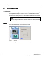
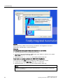
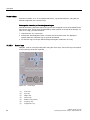
Additional applications ................................................................................................................ 54
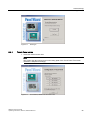
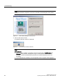
Touch Panel set-up ..................................................................................................................... 55
Key Panel adjustment ................................................................................................................. 58
RAID1 system (optional) ............................................................................................................. 59
8.5
BIOS settings .............................................................................................................................. 65
8.6
USB ............................................................................................................................................. 65
Operation and configuration..................................................................................................................... 67
9.1
9.1.1
9.1.2
9.1.3
Normal operation......................................................................................................................... 67
Switching on the device .............................................................................................................. 67
Logging on to the operating system using the on-screen keyboard ........................................... 69
Switching off the device .............................................................................................................. 69
9.2
9.2.1
9.2.2
9.2.3
9.2.4
9.2.5
9.2.6
9.2.7
9.2.8
9.2.9
9.2.10
9.2.11
Additional drivers and applications ............................................................................................. 70
Touch screen calibration ............................................................................................................. 70
Activate touch functionality.......................................................................................................... 71
Deactivate touch functionality ..................................................................................................... 72
Windows Security Center (Windows XP Professional / Windows XP Embedded)..................... 73
KeyTools (for key panel devices)................................................................................................ 74
On-screen keyboard (for touch panel device)............................................................................. 75
Panel PC Tools ........................................................................................................................... 76
CheckLanguageID ...................................................................................................................... 77
Multilingual settings for the operating system ............................................................................. 78
DVD burner ................................................................................................................................. 79
USB keyboard controller ............................................................................................................. 79
Operation................................................................................................................................................. 81
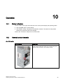
10.1
Status indicators.......................................................................................................................... 81
10.2
General control elements ............................................................................................................ 81
10.3
10.3.1
10.3.2
10.3.3
10.3.4
10.3.5
10.3.6
10.3.7
Device with key panel ................................................................................................................. 82
Safety .......................................................................................................................................... 82
Overview ..................................................................................................................................... 83
Keys ............................................................................................................................................ 84
External keyboards ..................................................................................................................... 87
Using the direct control key module............................................................................................ 87
Labelling function keys and softkeys .......................................................................................... 90
Using the integrated mouse ........................................................................................................ 91
10.4
10.4.1
Device with touch panel .............................................................................................................. 92
Operating a touch panel.............................................................................................................. 92
SIMATIC Panel PC 677B
Operating Instructions, 05/2007, A5E01035609-01
Table of contents
11
12
Functions ................................................................................................................................................. 93
11.1
Overview ......................................................................................................................................93
11.2
Safecard on Motherboard (SOM).................................................................................................94
11.3
Temperature monitoring...............................................................................................................95
11.4
Watchdog (WD)............................................................................................................................95
11.5
Fan monitoring .............................................................................................................................96
Maintenance and service......................................................................................................................... 97
12.1
Maintenance.................................................................................................................................97
12.2
Spare parts...................................................................................................................................99
12.3
Separating the control unit from the computer unit....................................................................100
12.4
12.4.1
12.4.2
12.4.3
12.4.4
12.4.5
12.4.6
12.4.7
12.4.8
12.4.9
12.4.10
12.4.11
12.4.12
12.4.13
12.4.14
Removing and installing hardware components ........................................................................103
Repairs.......................................................................................................................................103
Opening the Device ...................................................................................................................104
Removing/Installing Memory Module.........................................................................................106
Installing PCI / PCI express cards .............................................................................................109
Installing drives ..........................................................................................................................111
Installing/removing an on-board Compact Flash card ...............................................................116
Installing/removing an additional Compact Flash card ..............................................................119
Replacing the Backup Battery....................................................................................................122
Removing/Installing the Power Supply ......................................................................................125
Installing / removing the bus board............................................................................................128
Installing / removing the motherboard .......................................................................................129
Installing / removing the equipment fan .....................................................................................131
Installing / removing the power supply fan.................................................................................132
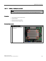
Installing / removing the processor ............................................................................................135
12.5
12.5.1
12.5.2
Reinstalling the operating system ..............................................................................................138
Windows XP Embedded ............................................................................................................138
Windows XP Professional / Windows 2000 Professional ..........................................................140
12.6
12.6.1
12.6.2
Partitioning the hard disk ...........................................................................................................147
Setting up the partitions under Windows XP Embedded...........................................................147
Setting up partitions under Windows XP Professional / Windows 2000 MUI ............................147
12.7
12.7.1
12.7.2
Installing drivers and software ...................................................................................................148
Installing drivers and software ...................................................................................................148
Driver installation under Windows XP Embedded .....................................................................148
12.8
Installing the RAID Controller software......................................................................................149
12.9
Installing the burner software.....................................................................................................149
12.10
Installing updates .......................................................................................................................150
12.10.1 Updating the operating system ..................................................................................................150
12.10.2 Installing or updating application programs and drivers ............................................................150
12.11
Data backup ...............................................................................................................................151
12.11.1 Creating an image......................................................................................................................151
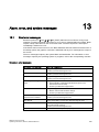
13
Alarm, error, and system messages ...................................................................................................... 153
13.1
Boot error messages..................................................................................................................153
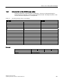
13.2
Introduction to the BIOS beep codes.........................................................................................155
SIMATIC Panel PC 677B
Operating Instructions, 05/2007, A5E01035609-01
5
Table of contents
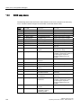
13.3
14
15
16
17
6
BIOS beep codes ...................................................................................................................... 156
Troubleshooting/FAQs........................................................................................................................... 159
14.1
General problems...................................................................................................................... 159
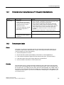
14.2
Problems when Using Modules of Third-party Manufacturers.................................................. 161
14.3
Temperature limits .................................................................................................................... 161
Specifications ........................................................................................................................................ 163
15.1
General specifications............................................................................................................... 163
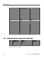
15.2
Power requirements of the components ................................................................................... 169
15.3
Device with AC voltage supply.................................................................................................. 170
15.4
Device with DC voltage supply ................................................................................................. 171
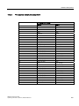
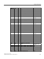
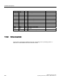
15.5
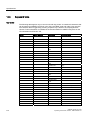
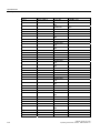
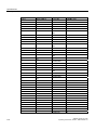
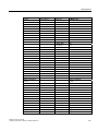
Keyboard table .......................................................................................................................... 172
Dimensional drawings............................................................................................................................ 179
16.1
Dimensional drawings Panel PC 677B ..................................................................................... 179
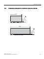
16.2
Dimensional drawings for the installation of expansion modules ............................................. 181
Detailed descriptions ............................................................................................................................. 183
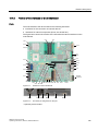
17.1
17.1.1
17.1.2
17.1.3
17.1.4
17.1.5
17.1.6
Motherboard.............................................................................................................................. 183
Structure and functions of the motherboard.............................................................................. 183
Technical features of the motherboard ..................................................................................... 184
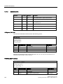
Position of the interfaces on the motherboard .......................................................................... 185
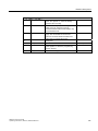
External ports ............................................................................................................................ 186
Front ports ................................................................................................................................. 191
Internal interfaces...................................................................................................................... 196
17.2
17.2.1
17.2.2
17.2.3
17.2.4
Bus board .................................................................................................................................. 200
Layout and principle of operation.............................................................................................. 200
PCI slot pin assignment ............................................................................................................ 201
Pin assignment 12 V power supply connection for WinAC module .......................................... 202
PCI Express slot x4 pin assignment ......................................................................................... 203
17.3
17.3.1
17.3.2
System resources ..................................................................................................................... 204
Currently allocated system resources....................................................................................... 204
System resources used by the BIOS/DOS ............................................................................... 204
17.4
17.4.1
17.4.2
17.4.3
17.4.4
17.4.5
17.4.6
17.4.7
17.4.8
17.4.9
17.4.10
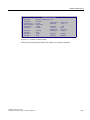
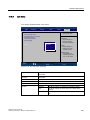
BIOS Setup ............................................................................................................................... 211
Overview ................................................................................................................................... 211
Starting BIOS Setup.................................................................................................................. 211
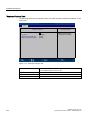
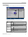
BIOS Setup menus ................................................................................................................... 212
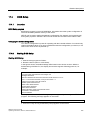
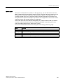
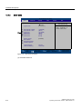
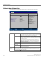
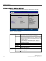
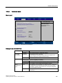
Main menu................................................................................................................................. 214
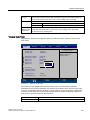
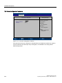
Advanced menu ........................................................................................................................ 225
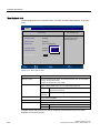
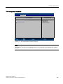
Security menu ........................................................................................................................... 231
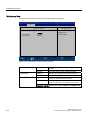
Boot Menu ................................................................................................................................. 233
Version Menu ............................................................................................................................ 234
Exit menu .................................................................................................................................. 235
BIOS Setup default settings ...................................................................................................... 236
A.1
Certificates and guidelines ........................................................................................................ 239
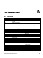
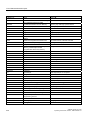
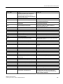
B.1
Abbreviations ............................................................................................................................ 245
SIMATIC Panel PC 677B
Operating Instructions, 05/2007, A5E01035609-01
1
Preface
Purpose of this manual
These operating instructions contain all the information you need for commissioning and
using the SIMATIC Panel PC 677B.
It is intended both for programming and testing personnel who commission the device and
connect it with other units (automation systems, programming devices), as well as for service
and maintenance personnel who install add-ons or carry out fault/error analyses.
Basic knowledge required
A solid background in personal computers and Microsoft operating systems is required to
understand this manual. General knowledge in the field of automation control engineering is
recommended.
Scope of this manual
This manual applies to devices with order numbers 6AV780.…
Approvals
For more information, please refer to the chapter "Certificates and Guidelines" in the
appendix.
CE marking
For more information, please refer to "Directives and Declarations" in the "Certificates and
Guidelines" section of the appendix.
Standards
Please refer to sections "Application planning" and "Technical data".
SIMATIC Panel PC 677B
Operating Instructions, 05/2007, A5E01035609-01
7
Preface
Position in the information landscape
The documentation for the Panel PC includes the following sections:
● SIMATIC Panel PC 677B, Operating Instructions (compact) with the following information:
– Commissioning
– Legal information
● SIMATIC Panel PC 677B, Operating Instructions
The documentation is supplied with the Panel PC in electronic form as a PDF file on the
"Documentation and Drivers" CD. The documentation is available in German, English,
French, Italian, Spanish, and Chinese.
Conventions
Representation
Validity
"File"
•
•
•
Terminology that appears in the user interface, for example
menu commands, tabs, buttons
Required input, for example limit values, tag values
Path information
"File > Edit"
Operational sequences, for example, menu commands, shortcut
menu commands
<F1>, <Shift>+<F1>
Keys and key combinations
The term "Panel PC 677B", "control unit" and "computer unit" is uniformly referred to as the
"device" in these operating instructions. The full term is only used when a concrete reference
is necessary.
Note
A note is important information about the product, handling the product or a reference to
specific sections of the documentation that require special consideration.
Trademarks
All names labeled with ® symbol are registered trademarks of Siemens AG. Other names
used in this documentation may be trademarks, the use of which by third parties for their
own purposes could violate the rights of the owner.
HMI®
SIMATIC®
SIMATIC HMI®
SIMATIC WinCC®
SIMATIC WinCC flexible®
Panel PC 677B®
8
SIMATIC Panel PC 677B
Operating Instructions, 05/2007, A5E01035609-01
2
Safety
2.1
Safety guidelines
Warning
Emergencies
In the event of a device fault, interrupt the power supply immediately. Inform the customer
service personnel responsible. Malfunctions can occur when the operator controls or power
cable are damaged or when liquids or foreign objects penetrate the device.
Warning
Following the results of a risk analysis, additional protection equipment on the machine or
the system is necessary to avoid endangering persons. With this, especially the
programming, configuration and wiring of the inserted I/O modules have to be executed, in
accordance with the safety performance (SIL, PL or Cat.) identified by the necessary risk
analysis. The intended use of the device has to be ensured.
The proper use of the device has to be verified with a function test on the system. This test
can detect programming, configuration and wiring errors. The test results have to be
documented and, if necessary, entered into the relevant documents that verify safety.
Note
This device corresponds to the regulations of the EU low-voltage directive and the GPSG,
verified by conformity with national and international standards (DIN EN, IEC) by a UL
approval (cULuc). Please comply with all the information in these operating instructions
when assembling the device.
SIMATIC Panel PC 677B
Operating Instructions, 05/2007, A5E01035609-01
9
Safety
2.1 Safety guidelines
Electrical connection
Warning
Disconnect the device from the mains before every intervention.
Do not touch power lines or data transmission lines during electrical storms and do not
connect any cables.
System expansions
Only install system expansion devices designed for this device. If you install other
expansions, you may damage the system or violate the safety requirements and regulations
for radio frequency interference suppression. Contact your technical support team or where
you purchased your PC to find out which system expansion devices may safely be installed.
Caution
If you install or exchange system expansions and damage your device, the warranty
becomes void.
High frequency radiation
Caution
Unintentional operating situations
High frequency radiation, from cell phones for example, can cause unintentional operating
situations under some circumstances. Further information is available in the section "EMC
requirements" of the "Technical data" chapter.
10
SIMATIC Panel PC 677B
Operating Instructions, 05/2007, A5E01035609-01
Safety
2.1 Safety guidelines
Handling and disposal of lithium batteries
Warning
Danger of explosion and the release of harmful substances!
Do not throw lithium batteries into fire, do not solder onto the cell body, do not open, do not
short circuit, do not reverse pole, do not heat above 100 °C, dispose of according to
regulations, and protect from direct sunlight, moisture and condensation.
Replace lithium batteries with the same brand or a brand recommended by the
manufacturer.
Dispose of used lithium batteries as hazardous waste, individually, in accordance with the
local regulations.
Repairs
Only authorized personnel are permitted to repair the device.
Warning
Unauthorized opening of and improper repairs to the device may result in substantial
damage to equipment or risk of personal injury to the user.
SIMATIC Panel PC 677B
Operating Instructions, 05/2007, A5E01035609-01
11
Safety
2.2 General Information
2.2
General Information
Overview
Caution
The device must only be operated in closed rooms. Failure to comply nullifies the warranty
Operate the device only in acordance with the ambient conditions specified in the technical
specifications. Protect the device against dust, moisture and heat. Do not place the device in
direct sunlight.
Transport
Unpack the device at its installation location. Transport the device only in the original
packaging. Do not transport the device when it is mounted.
Notice
Adhere to these stipulations each time the device is transported, otherwise the guarantee is
void.
Caution
Condensation
When transporting the device at low temperatures, ensure that no moisture gets on or into
the device. This also applies if the device is subjected to extreme changes in temperature.
Commissioning
Allow the device to slowly adjust to room temperature before commissioning the device. Do
no place the device near heat radiation. If moisture condensation occurs, wait at least 12
hours before you switch on the device.
Vibration
Optical drives are sensitive to vibration. Inadmissible vibration during operation may result
in loss of data or damage to the drive or data medium.
Before transporting the device, wait at least 20 seconds to allow the drive to stop
completely.
12
SIMATIC Panel PC 677B
Operating Instructions, 05/2007, A5E01035609-01
Safety
2.2 General Information
Tools & downloads
Please check regularly if updates and hotfixes are available for download to your device.
Downloads are available on the Internet at
http://www.siemens.com/asis under "Support".
Click "Overview of Panel PCs" under "Tools & Downloads". Using the global search function,
you can then also search for any downloads you require.
Optical drive
Notice
An optical drive should only be operated in a mechanically undisturbed environment without
vibrations and shock.
Safety-relevant applications
Warning
Maloperation
Do not perform safety-relevant functions of the user software with the touch screen.
Resistance to chemicals
Caution
Adhere to the information regarding chemical resistance of the panel front. You can find
information on the Internet under
"Tools & Downloads > Downloads > Product > Support > Industrial PC":
http://www.siemens.com/asis
Enter the article ID 22591016 as the search term. The available articles are displayed.
SIMATIC Panel PC 677B
Operating Instructions, 05/2007, A5E01035609-01
13
Safety
2.2 General Information
Sources of light
Notice
Position the screen so that it is not subject to direct sunlight or other strong sources of light.
Defective pixels in the display
At present, the manufacturing process of modern displays does not guarantee that all pixels
of the display will be perfect. A small number of defective pixels in the display is therefore
unavoidable. This does not present a functional problem as long as the defective pixels are
not bunched in one location.
Further information is available in the section "General technical data" of the "Technical
data" chapter.
Burn-in effect on TFT displays
A permanent picture with bright images can lead to a burn-in effect on the TFT LCD.
If a screen saver is activated, please observe the following:
● The liquid crystals in screen savers which actuate active black when the backlighting is
on, e.g. flying stars "starfield simulation," renew themselves. Pay attention to the length of
time the backlighting is activated
● The following applies to screen savers that turn off the backlighting: Each time the
backlighting is turned on, its life is reduced by 50 minutes.
Consider the following carefully:
● Screen saver
● Switch off the backlighting regularly
● Permanent display of the customer application
14
SIMATIC Panel PC 677B
Operating Instructions, 05/2007, A5E01035609-01
Safety
2.3 ESD directives
2.3
ESD directives
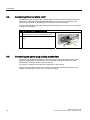
What does ESD mean?
Almost all electronic modules are equipped with highly integrated components and elements
in MOS technology. For technological reasons, these electronic components are very
sensitive to overvoltages and, consequently, to electrostatic discharge. These components
are therefore marked as follows:
● ESD: Electrostatically Sensitive Devices
● ESD: Internationally recognized marking for components and modules susceptible to
electrostatic discharge
The following symbols on switch cabinets, module carriers or packaging indicate their
susceptibility to electrostatic discharge:
ESD components are destroyed by voltage and energy far below the limits of human
perception. Voltages of this kind occur as soon as a device or an assembly is touched by a
person who is not electrostatically discharged ESD components which were subject to such
voltage are usually not recognized immediately as being defective, because the malfunction
does not occur until after a longer period of operation.
Note
More information is located on the rating label. The rating label is described in the chapter
"Planning use."
Precautions against electrostatic discharge
Most plastics can be charged easily. Therefore, keep plastics away from ESD components!
When working with electrostatically sensitive components, make sure that the person, the
workstation and the packaging are properly grounded. Conduct the electrostatic charge
away from your body by touching the mounting plate for the interfaces, for example.
SIMATIC Panel PC 677B
Operating Instructions, 05/2007, A5E01035609-01
15
Safety
2.3 ESD directives
Handling ESD modules
As a rule: Only touch ESD components if unavoidable due to necessary tasks.
Only touch the components when the following holds true:
● You are permanently grounded by means of an ESD armband.
● You are wearing ESD shoes or ESD shoes grounding protective strips in connection with
ESD floors.
Before you touch an electronic assembly, your body must be discharged. Touch a
conductive object immediately beforehand, e.g. a bare metal part of a switch cabinet or the
water pipe.
Do not allow chargeable, highly insulated materials, e.g. plastic films, insulating tabletops,
synthetic clothing fibers, to come into contact with ESD components.
Place ESD components only on conductive surfaces (work surfaces with ESD surface,
conductive ESD foam, ESD packing bag, ESD transport container).
Do not expose ESD components to visual display units, monitors or televisions. Maintain a
distance of at least 10 cm to screens.
Handle flat components only by their edges. Do not touch component connectors or
conductors. This prevents charges from reaching and damaging sensitive components.
Measuring and modifying ESD components
Measure the ESD component under the following conditions only:
● The measuring device is grounded with a protective conductor, for example.
● The probe on the potential-free measuring device has been discharged, e.g. by touching
the bare metal of a part of the switch cabinet.
● Your body is discharged. To do so, touch a grounded metallic object.
Solder only with grounded soldering irons.
Shipping ESD modules
Always store or ship ESD components in conductive packaging, e.g. metallized plastic boxes
or metal cans. Leave the components and parts in their packaging until installation.
If the packaging is not conductive, wrap the ESD component in a conductive material, e.g.
rubber foam, ESD bag, household aluminum foil, or paper, before packing. Do not wrap the
ESD component in plastic bags or plastic film.
In ESD components containing installed batteries, make sure that the conductive packaging
does not touch the battery connectors or short circuit. Insulate the connectors with suitable
material.
16
SIMATIC Panel PC 677B
Operating Instructions, 05/2007, A5E01035609-01
3
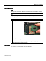
Description
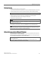
3.1
Panel PC 677B design
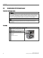
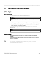
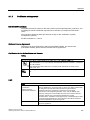
Design
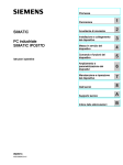
Figure 3-1
Panel PC 677B
(1)
Computer unit
(2)
Control unit
Product Brief
The device is available with different control units which are distinguished by the size of the
display and by the key or touch panel.
SIMATIC Panel PC 677B
Operating Instructions, 05/2007, A5E01035609-01
17
Description
3.1 Panel PC 677B design
Key panel variants
● Color display with backlighting:
– 12'' TFT technology with 800 x 600 resolution
– 15'' TFT technology with 1024 x 768 resolution
● Membrane keyboard with alphanumeric keys, numeric keys, cursor keys and control keys
● Function keys and softkeys
● Integrated mouse
● LEDs for power supply, temperature, softkeys, <Shift> and <ACK> function keys and
buttons
● Front-mounted USB 2.0 interface for connecting external I/O devices. All fronts are also
available without USB interfaces accessible from the front
Key panel variants
● Color display with backlighting
– 12" TFT technology; 800 x 600 resolution
– 15" TFT technology; 1024 x 768 resolution
– 17" TFT technology; 1280 x 1024 resolution
– 19" TFT technology; 1280 x 1024 resolution
● LEDs for power supply and temperature
● Front-mounted USB 2.0 interface for connecting external I/O devices. All fronts are also
available without USB interfaces accessible from the front
Refer to the "Specifications" section for more information.
18
SIMATIC Panel PC 677B
Operating Instructions, 05/2007, A5E01035609-01
Description
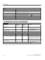
3.2 Features
3.2
Features
Basic data
Design
Panel mounting device, computer unit
Processor
•
•
•
Intel ® Celeron M 440 1.86 GHz
533 MHz Front Side Bus (FSB),
1024 KB Second Level Cache
Intel ® Core 2 Duo 1.66 GHz T5500
667 MHz Front Side Bus
2048 KB Second Level Cache
Intel ® Core 2 Duo 2.16 GHz T7400
667 MHz Front Side Bus,
4096 KB Second Level Cache
RAM
•
•
512 MB SDRAM (DDR2)
Expandable up to 4 GB SDRAM (DDR2)
Slots for add-ons
•
•
1x PCI 265 mm long and 1x PCI 175 mm long
1x PCI 265 mm long and 1x PCI Express x4 175 mm
long
Graphics
•
•
•
Graphics memory 8 to 128 MB SDRAM, partially
using dynamic sharing of system RAM
VGA: 1600 x 1200 / 32-bit color depth / 85 Hz
DVI-I: 1600 x 1200 / 32-bit color depth / 60 Hz
•
•
120 V / 230 V AC, 190 W; varying voltage
24 V DC, 210 W
Power supply
Both with bridging of transient loss of voltage according
to NAMUR: Max. 20 ms at 0.85 rated voltage
Drives and storage media
1 x 3.5" hard disk
2 x 2.5" hard disk or RAID1 system
Capacity see order forms
Hard disk drives
•
•
DVD drive
DVD burner
Flash drive
Slot for Compact Flash card
Ports
Ethernet
2x 10/100/1000 Mbps (RJ45)
PROFIBUS/MPI
12 Mbps (isolated potential, compatible to CP 5611),
optional
USB
•
COM
Serial V.24 port
Monitor
1x DVI-I (VGA monitors can be operated with a DVI/VGA
adapter)
•
SIMATIC Panel PC 677B
Operating Instructions, 05/2007, A5E01035609-01
External: 4 x USB 2.0 on the interface side
(max. 2 can be simultaneously operated as high
current)
Front panel ports: USB 2.0 high current
19
Description
3.2 Features
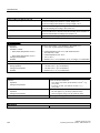
Monitoring and safety functions
Temperature
•
•
When permitted temperature range is exceeded
Warning messages from application program that can
be analyzed: local, via LAN (DiagMonitor, optionally
available )
Fans
•
•
Failure of device and power supply fans
Warning messages from application program that can
be analyzed: local, via LAN (DiagMonitor, optionally
available )
Watchdog
•
•
•
Monitoring function for program execution
Restart can be parameterized in the event of a fault
Warning messages from application program that can
be analyzed: local, via LAN (DiagMonitor, optionally
available )
Transient voltage interruption
Up to 20 ms buffer time with full load
Buffer memory
Battery-buffered SRAM
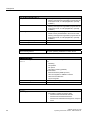
Optional accessories
Book mounting bracket
For space optimizing installation in switch cabinet
Optional expansions
SIMATIC PC DiagMonitor software
≥ V 3.1
Software tool for monitoring local and remote SIMATIC
PCs:
• Watchdog
• Temperature
• Fan speed
• Hard disk monitoring (SMART)
Communication:
• Ethernet interface (SNMP protocol)
• OPC for integration in SIMATIC software
• Client server architecture
• Layout of log files
SIMATIC PC Image Creator software
Software tool for saving data locally
PCI Multi-I/O module
Provides one parallel and one serial interface
Software
Operating systems
20
•
•
Without
Preinstalled / supplied on Restore DVD:
– Windows 2000 Professional SP4 MUI
– Windows XP Professional SP2 MUI
– Windows XP embedded SP2 English on Compact
Flash
SIMATIC Panel PC 677B
Operating Instructions, 05/2007, A5E01035609-01
Description
3.3 Panel PC 677B accessories
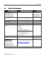
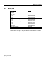
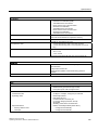
3.3
Panel PC 677B accessories
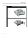
Accessories
Comment
Order No.
Direct control key module
6AV7671-7DA00-0AA0
Foil for protecting the touch panel against
dirt and scratches
for the 12" touch panel variant
for the 15" touch panel variant
for the 17" touch panel variant
for the 19" touch panel variant
6AV7671-2BA00-0AA0
6AV7671-4BA00-0AA0
6AV7672-1CF00-0AA0
6AV7672-1CE00-0AA0
Film for labeling the function keys
(slide-in labels)
You can find print templates for the slide-in labels
are available on the "Documentation and Drivers"
CD.
6AV7672-0DA00-0AA0
DVI / VGA adapter
6ES7648-3AB00-0XA0
Backing plate for screw fixing of the 17"
and 19" touch panel
6AV7672-8KE00-0AA0
External USB disk drive
1 m connecting cable
6FC5235-0AA05-1AA1
PCI multi-I/O module
Provides one parallel and one serial interface
6ES7648-2CA00-0AA0
SIMATIC PC DiagMonitor
software ≥ V 3.1
Software tool for monitoring local and remote
SIMATIC PCs:
• Watchdog
• Temperature
• Fan speed
• Hard disk monitoring (SMART)
• System / Ethernet monitoring (Heart Beat)
6ES7648-6CA02-2YX0
Communication:
• Ethernet interface (SNMP protocol)
• OPC for integration in SIMATIC software
• Client server architecture
• Layout of log files
SIMATIC PC Image Creator software
Software tool for saving data locally
6ES7648-6AA03-0YX0
Module for DDR2 RAM expansion
512 MB
1 GB
2 GB
6ES7648-2AG30-0HA0
6ES7648-2AG40-0HA0
6ES7648-2AG50-0HA0
Remote Kit order variant
Remote Kit, 24 V DC, 5 m
Remote Kit, 24 V DC, 10 m
Remote Kit, 24 V DC, 20 m
Remote Kit, 24 V DC, 30 m
Remote Kit, 100/240 V AC, 5 m
Remote Kit, 100/240 V AC, 10 m
Remote Kit, 100/240 V AC, 20 m
Remote Kit, 100/240 V AC, 30 m
You can find ordering information on the Internet
under:
http://www.siemens.com/automation/mall
You can find additional accessories in the catalog or in the Internet under: http://www.siemens.com/automation/mall
SIMATIC Panel PC 677B
Operating Instructions, 05/2007, A5E01035609-01
21
Description
3.3 Panel PC 677B accessories
22
SIMATIC Panel PC 677B
Operating Instructions, 05/2007, A5E01035609-01
Application planning
4.1
4
Overview
Introduction
This section describes the first steps after unpackaging, the permitted mounting positions
and the fixation. This section describes the necessary considerations for EMC.
Field of application
The Panel PC is an industry-standard PC platform for demanding tasks in the field of PCbased automation. The Panel PC is designed for on-site use on the machine, installed for
example in:
● Control cabinet installation
● Swivel arm mounting
● Rack mounting
Note
In the following, the term "switchgear cabinet" also refers to rack, mounting rack,
switchboard, operator panel and console. The term "device" represents the Panel PC and
its variants.
SIMATIC Panel PC 677B
Operating Instructions, 05/2007, A5E01035609-01
23
Application planning
4.2 Unpacking and checking the delivery
4.2
Unpacking and checking the delivery
Procedure
1. Please check the packaging material for transport damage upon delivery.
2. If any transport damage is present at the time of delivery, lodge a complaint at the
shipping company in charge. Have the shipper confirm the transport damage
immediately.
3. Unpack the device.
Caution
Do not lie the device on its back. This will avoid any damage to an optical drive which
may be present. Lie the front side on a soft surface to avoid damaging the front panel
USB port.
4. Keep the packaging material in case you have to transport the unit again.
Notice
The packaging protects the device during transport and storage. Therefore, never
dispose of the original packaging material!
5. Please keep the enclosed documentation in a safe place. You will need the
documentation when you start up the device for the first time.
6. Check the package contents for completeness and any visible transport damage. Check
for completeness using the enclosed scope of delivery list.
7. Should the contents of the package be incomplete or damaged, please inform the
responsible supply service immediately and fax us the enclosed form "SIMATIC IPC/PG
quality control report".
Warning
Make sure that a damaged device is not installed nor put into operation.
8. Note the identification information as described in the chapter "Identification data of the
device".
24
SIMATIC Panel PC 677B
Operating Instructions, 05/2007, A5E01035609-01
Application planning
4.3 Device identification data
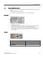
4.3
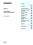
Device identification data
The device can be clearly identified with the help of this identification data in case of repairs
or theft.
Enter the following data in the table below:
● Serial number: The serial number (S VP...) is found on the rating plate.
Rating plate
SIMATIC Panel PC 677B
6AV7870-1AB00-0AA0
● Order number of the device
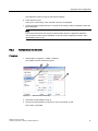
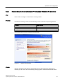
● Ethernet addresses: The Ethernet addresses of the device can be viewed in the BIOS
Setup (F2) under "Main > Hardware Options > Onboard Ethernet Address".
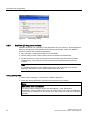
● Microsoft Windows "Product Key" on the "Certificate of Authenticity" (COA). The COA
label is bonded to the device. The Product Key is always required to reinstall the
operating system.
COA label
Serial number:
S VP ...
Order No.
6AV787.....
Microsoft Windows Product Key
Ethernet address 1
Ethernet address 2
SIMATIC Panel PC 677B
Operating Instructions, 05/2007, A5E01035609-01
25
Application planning
4.4 Mounting positions and fastening
4.4
Mounting positions and fastening
4.4.1
Installation guidelines
Before installing the device, read the following general notes relating to installation.
Warning
Danger, high voltage
Isolate the power supply to the switchgear cabinet before opening it. Ensure that the power
to the switchgear cabinet cannot be turned on accidentally.
Caution
The device is approved for operation in closed rooms only.
● Ensure that the protective contact socket of the building installation is easily accessible
and that there is a mains disconnect switch in switchgear cabinet installations.
● Position the screen in an ergonomic position favorable to the user. Choose a suitable
installation height.
● Position the screen so that it is not subject to direct sunlight or other strong sources of
light.
● Optical drives are susceptible to shock. Shocks during operation can lead to the loss of
data or damage to the drive or data carrier. Optical drives are not only suitable for
continuous operation.
● Applies to devices which are installed in swivel arm housings: Avoid rapid or jerky
movements of the swivel arm during operation. The ensuing forces could lead to possible
irreversible damage of the hard disk.
The stops of the swivel arm must be damped in order to avoid any mechanical shock
effect to the Panel PC on attachment.
● Applies to devices which are installed in cabinet doors: Prevent the doors being slammed
shut. The ensuing forces could lead to possible irreversible damage of the hard disk.
● The device wtih DC power supply applies in the area of the computer unit and above all
the power supply connection in accordance with the UL approval as "open type" or "open
equipment". For this reason, the device must be installed in a control cabinet or housing
that complies with fire-proofing requirements
26
SIMATIC Panel PC 677B
Operating Instructions, 05/2007, A5E01035609-01
Application planning
4.4 Mounting positions and fastening
Note
The computer unit with AC power supply satisfies fire protection requirements to EN
60950-1. It may therefore be installed without additional fire-proofing measures.
● Provide adequate volume in the switchgear cabinet for air circulation and heat transport.
Keep at least 10 cm distance between the device and switchgear cabinet.
● Ensure that the maximum air intake temperature, measured 10 cm before the air intake
opening on the fan, does not exceed 45°C. The maximum air intake temperature must be
accounted for especially when sizing closed switchgear cabinets.
● The minimum distance between the device and the housing is 10 cm on the air output
side at the fan.
● Position the device in such a way that the air vents of the housing are not covered up
following mounting.
● Ensure there is enough free space in the switchgear cabinet to allow the sheet metal
cover to be removed. You will otherwise have to remove the device from the switchgear
cabinet or swivel arm when replacing memory or the battery.
● Equip the switchgear cabinet with struts for stabilizing the mounting cut-out. Install struts
where necessary.
● Avoid extreme environmental operating conditions. Protect your device against dust,
moisture and heat.
● Install the device in such a way that it poses no danger, e.g. by falling over (see Chapter
"Specifications").
● During assembly, please comply with the approved installation positions.
Notice
If you mount the device in an impermissible installation position or you do not observe
the environmental conditions (see Chapter "Specifications"), you endanger the product
safety provided by the UL-approval and compliance with the low-voltage directive (via
EN 60950-1). In additional, the functionality of the device is no longer guaranteed.
For additional information, refer to the dimension diagrams in the appendix.
SIMATIC Panel PC 677B
Operating Instructions, 05/2007, A5E01035609-01
27
Application planning
4.4 Mounting positions and fastening
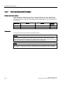
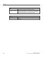
4.4.2
Permitted mounting positions
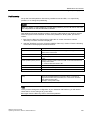
Approval
Only certain mounting positions are approved for the device.
$
%
Figure 4-1
Mounting position
Table 4-1
Permissible deviations from the vertical mounting position
Temperature
Angle A
Angle B
to 45°C
20°
20°
Note
When mounting the device at an angle, note the following.
• Do not subject the device to mechanical stress.
• Operation of a DVD drive is not permitted.
4.4.3
Type of fixation
The computer unit is secured in the mounting cut-out either with clamps or screws.
Notice
Securing with screws is not possible with the 12" touch screen variant.
Select the type of fixation suitable to your requirements for the degree of protection (see
section "Protection against dust and water").
28
SIMATIC Panel PC 677B
Operating Instructions, 05/2007, A5E01035609-01
Application planning
4.4 Mounting positions and fastening
4.4.4
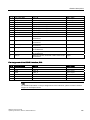
Protection against dust and water
Principle
With the relevant installation, the device is protected on the front agains the ingress of dust
and water. The "degree of protection" is in accordance with IEC 60529: On the front, the
device has degree of protection IP65, the rear of the operator section and the computer unit
have degree of protection IP20.
Caution
Ensure that the material strength at the mounting cut-out is a minimum of 2 mm and a
maximum of 6 mm. Please follow the specifications for the dimensions in the "Mounting cutout" section.
The degrees of protection IP65, IP54 and NEMA 4, are only guaranteed when the following
conditions are met:
• The surface plane deviation of the mounting cut-out in relation to the external
dimensions of the control unit amounts to ≤ 0.5 mm when the control unit is mounted.
Degree of protection IP65 and NEMA 4
IP65 degree of protection and compliance with the NEMA 4 regulations are only ensured
when clamp mounting together with a ring seal.
IP54 degree of protection
The IP54 degree of protection is applicable for the following conditions:
Key panel
Touch panel
12"
15"
15"
17"
19"
Screw mounting
X
X
X
-
-
Screw mounting with backing
plate
-
-
-
X
X
Note
A backing plate is available as an accessory for screw mounting the 17" and 19" touch
panel. You can find additional information under:http://www.siemens.com/automation/mall
SIMATIC Panel PC 677B
Operating Instructions, 05/2007, A5E01035609-01
29
Application planning
4.5 Mounting cut-out
4.5
Mounting cut-out
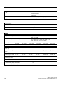
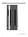
4.5.1
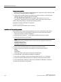
Preparing the mounting cut-out
The following illustration shows the dimensions for the mounting cut-out.
$
/
$
/
/
/
6
6
/
/
6
/
/
6 6
/
/
/
/
6
6
/
PP
/
Figure 4-2
Drill holes for the screws and pressure points for the clamp screws
(1)
Drill hole for screw attachment
(4)
Clamp
(2)
Pressure points for clamp
(5)
RZ 120 in the seal area
(3)
Setscrews
(6)
Seal area
Note
Mounting dimensions can be read from the dimension overview or they can be transferred to
the cabinet from the mounting template supplied.
30
SIMATIC Panel PC 677B
Operating Instructions, 05/2007, A5E01035609-01
Application planning
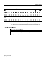
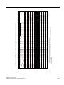
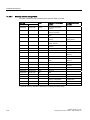
4.5 Mounting cut-out
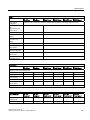
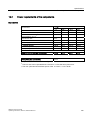
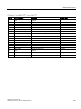
Table 4-2
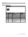
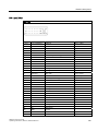
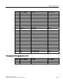
Dimensions for the mounting cut-out in mm
Control
unit
L1
L2
L3 1)
L4 1)
L5
L6 2)
L7 2)
L8 2)
L9 2)
A1
A2
S1
S2
S3
S4
S53)
S63)
S73)
Tolerance
±1
+1
±0,2
±0,2
±0,5
±0,5
±0,5
±0,5
+1
±1
±1
±1
±1
±1
±1
Key
panel
12" TFT
15" TFT
450
450
290
321
465
465
235
279
112
112
—
186
—
135
—
25
—
165
16
16
10
17
78
51
78
51
56
56
—
—
Touch
panel
12" TFT
15" TFT
17" TFT
19" TFT
368
450
450
450
290
290
380
380
—
465
465
465
—
235
235
235
112
112
112
112
—
—
—
—
—
—
—
—
—
—
—
—
—
—
—
—
16
16
16
16
10
10
10
10
19
81
46
46
35
81
46
46
56
56
—
—
—
—
33
33
1)
M6 thread or drill holes with a diameter of 7 mm
2)
Cut-outs for the shafts of the insert strips are only necessary for 15" key panels.
3)
Two clamps necessary for vertically securing clamps for 17" and 19" touch panels only.
Preparing the mounting cut-out
Steps for preparing the mounting cut-out
1
Select a location suitable for mounting, taking into account the mounting position.
2
On the basis of the dimensions, check whether the required screw and pressure points on the
rear and the seal area are easily accessible after the completion of the mounting cut-out.
Otherwise the mounting cut-out is useless.
3
Complete the mounting cut-out in accordance with the dimensions.
SIMATIC Panel PC 677B
Operating Instructions, 05/2007, A5E01035609-01
31
Application planning
4.5 Mounting cut-out
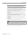
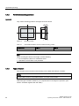
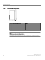
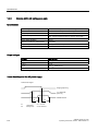
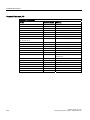
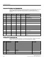
4.5.2
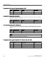
Mounting depth of the device
7
Panel PC with operator control units
Depth D
Key panel with 12" TFT
105 mm
Key panel with 15" TFT
124 mm
Touch panel with 12" TFT
123 mm
Touch panel with 15" TFT
121 mm
Touch panel with 17" TFT
130 mm
Touch panel with 19" TFT
130 mm
Note
Additional mounting depth with optical drive
The installation depth increases by 21 mm when an optical drive is installed in the device.
32
SIMATIC Panel PC 677B
Operating Instructions, 05/2007, A5E01035609-01
Application planning
4.6 EMC Guideline
4.6
EMC Guideline
Electromagnetic compatibility
The device fulfills the requirements of the EMC law of the Federal Republic of Germany as
well as the EMC directive of the Single European Market.
The device is designed as a built-in device. You can ensure compliance with the EN 610004-2 (ESD) EMC standard by installing the device in grounded metal cabinets (for example, 8
MC cabinets, Siemens catalog NV21).
Note
For additional information about EMC requirements, refer to the Specifications section.
Installing the device according to EMC directive
Basics for interference-free operation:
● Install the controller according to EMC directive
● Use interference immune cable
Note
The instructions "Guidelines for the assembly of interference immune programmable logic
controllers" with the article ID 1064706 and the manual "PROFIBUS networks" with the
article ID 1971286, which also applies to the installation of the device, is located on the
"Documentation and Drivers" CD.
SIMATIC Panel PC 677B
Operating Instructions, 05/2007, A5E01035609-01
33
Application planning
4.6 EMC Guideline
34
SIMATIC Panel PC 677B
Operating Instructions, 05/2007, A5E01035609-01
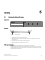
5
Mounting
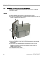
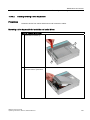
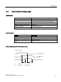
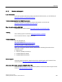
5.1
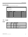
Securing the device with clamps
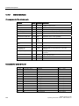
Requirement
Accessories
Display
Clamp
12"
15"
17"
19"
6x
6x
8x
8x
The clamps are provided with the control unit.
Tool
2.5 mm hexagonal spanner
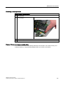
Procedure
Figure 5-1
Clamp assembly
1. Disconnect the device from the power supply.
2. Working from the front, insert the device into the 19" rack on the swivel arm or in the
mounting cut-out.
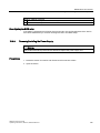
3. Fasten the control unit from the rear using the clamps.
4. Tighten the setscrews to a torque of 0.4 - 0.5 Nm.
IP65 degree of protection
The plant builder is responsible for the correct installation of the device.
The degree of protection IP65 is only guaranteed for the front of the device if the ring seal is
properly applied with the correct size of cutout, the unit has been clamped in place, and the
instructions below are observed.
SIMATIC Panel PC 677B
Operating Instructions, 05/2007, A5E01035609-01
35
Mounting
5.1 Securing the device with clamps
Notice
Control cabinet installation: Material strength at the mounting cut-out
Ensure that the material strength at the mounting cut-out is a minimum of 2 mm and a
maximum of 6 mm. Please follow the specifications for the dimensions in the "Preparing the
mounting cut-out" section.
The degrees of protection are only guaranteed when the following is observed:
• The surface plane deviation of the mounting cut-out in relation to the external
dimensions of the control unit amounts to ≤ 0.5 mm when the control unit is mounted.
36
SIMATIC Panel PC 677B
Operating Instructions, 05/2007, A5E01035609-01
Mounting
5.2 Securing with screws
5.2
Securing with screws
Note
Securing with screws is not possible with the 12" touch panel variant. To secure the 17" and
19" touch panel with screws, backing plates with order number 6AV7672-8KE00-0AA0 are
required on the front.
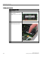
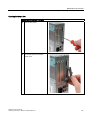
Drill holes in the control unit
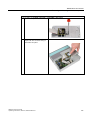
Steps for drilling holes
1
Drill holes (Ø approx. 2.5 mm) from the rear in the four recesses of the control unit
2
Drill these holes with a diameter of Ø 5.5 mm for M5 and a Ø 6.5 mm for M6.
3
Deburr the holes from the front of the control unit
Notice
Risk of damage
Ensure that no metal cuttings enter the device when the holes are drilled. Cover the device
with film or when drilling, use removal by suction.
SIMATIC Panel PC 677B
Operating Instructions, 05/2007, A5E01035609-01
37
Mounting
5.2 Securing with screws
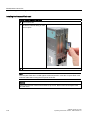
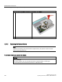
Drill holes in the mounting unit
1. Drill the holes at the prepared mounting cut-out according to the information for L3 and
L4. (see Chapter "Mounting cut-out" )
2. Working from the front, insert the device into the 19" rack on the swivel arm or in the
mounting cut-out of the control cabinet.
3. Secure the control unit by inserting suitable screws and nuts
IP54 degree of protection
The IP54 degree of protection is guaranteed for mounting together with the ring seal.
Caution
Observe the panel seal when mounting
Ensure you do not damage the panel seal when mounting the device.
Notice
Control cabinet installation: Material strength at the mounting cut-out
Ensure that the material strength at the mounting cut-out is a minimum of 2 mm and a
maximum of 6 mm. Please follow the specifications for the dimensions in the "Preparing the
mounting cut-out" section.
The degrees of protection are only guaranteed when the following is observed:
• The surface plane deviation of the mounting cut-out in relation to the external
dimensions of the control unit amounts to ≤ 0.5 mm when the control unit is mounted.
38
SIMATIC Panel PC 677B
Operating Instructions, 05/2007, A5E01035609-01
6
Connecting
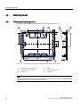
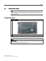
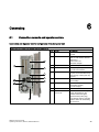
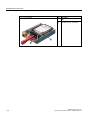
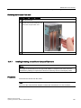
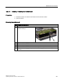
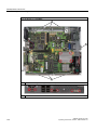
6.1
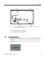
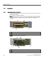
Connection elements and operator controls
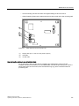
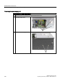
Connection and Operator Control Components of the Computer Unit
Locations of connection and operator control components
Pos
Name
Description
(1)
PCI (e)
2 slots for PCI expansion
module
(2)
DVI/VGA
DVI/VGA socket for
CRT or LCD monitor with DVI
interface or
VGA monitor via
DVI/VGA adapter
(3)
Compact Flash
Slot for Compact Flash card
(4)
COM 1
Serial port (RS232)
9-pin D-sub connector
(5)
USB
4 USB 2.0 ports
(2 ports can be simultaneously
used as high current (500 mA)
outputs)
(6)
Ethernet
2 RJ45 connections for
10/100 Mbps
(7)
PROFIBUS DP/MPI
MPI interface (RS485,
electrically isolated),
9-pin D-sub plug
(8)
On / Off switch
-
(9)
100 - 240 V AC
or 24 V DC
Connection for AC or DC power
supply (depending on the
product variant, the figure
shows the AC power plug)
The relevant angle is included
with the device for interlocking
the connector.
SIMATIC Panel PC 677B
Operating Instructions, 05/2007, A5E01035609-01
39
Connecting
6.1 Connection elements and operator controls
Notice
On / Off switch
The On / Off switch does not disconnect the device from the mains. When the switch is in
the 0 position, the device is still connected to the auxiliary voltage.
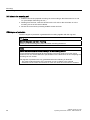
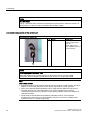
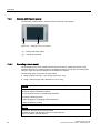
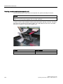
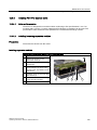
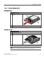
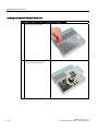
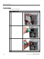
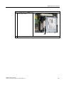
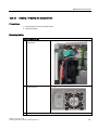
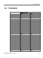
Connection components of the control unit
USB connection control unit
Pos
Name
Description
(1)
USB
1 connection
USB 2.0 high current /
500 mA
under sealed cover
(not available with every
product variant).
Notice
Ensuring degree of protection P65
When the sealed cover over the USB port is removed in order to connect a USB
component, the IP65 degree of protection for the device is no longer guaranteed.
Note
Use of USB devices
• Wait at least ten seconds between removal and reconnection of USB devices. This also
applies to control units with touch screen panels, especially for touch operation.
• When using standard USB peripherals, bear in mind that their EMC immunity level is
frequently designed for office applications only. These devices may be used for
commissioning and servicing. However, only industry-standard devices are allowed for
industrial operation.
• Peripherals are developed and marketed by individual vendors. The respective
manufacturers offer support for the peripherals. Moreover, the terms of liability of the
individual vendors or suppliers apply here.
40
SIMATIC Panel PC 677B
Operating Instructions, 05/2007, A5E01035609-01
Connecting
6.2 Connecting the 120 V / 240 V Ac power supply
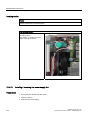
6.2
Connecting the 120 V / 240 V Ac power supply
Note before connecting the device
Note
The varying voltage power supply module is designed for operation on 120 / 240 V AC
networks. The setting of the voltage range takes place automatically.
Warning
Do not connect or disconnect power and data cables during thunderstorms.
Warning
The device is designed for operation on grounded power supply networks (TN networks to
VDE 0100, Part 300, or IEC 60364-3).
Operation on ungrounded or impedance-grounded power networks (IT networks) is
prohibited.
Warning
The permitted nominal voltage of the device must conform with local mains voltage.
Caution
The mains connector must be disconnected to fully isolate the device from the mains.
Ensure easy access to this area.
A master mains disconnect switch must be installed if the device is mounted in a switch
cabinet.
Always ensure free and easy access to the power inlet on the device or that the safety
power outlet of the building installation is freely accessible and located close to the device.
SIMATIC Panel PC 677B
Operating Instructions, 05/2007, A5E01035609-01
41
Connecting
6.2 Connecting the 120 V / 240 V Ac power supply
Note
The power supply contains an active PFC (Power Factor Correction) circuit to conform to the
EMC guidelines.
Uninterruptible AC power systems (UPS) must supply a sinusoidal output voltage in the
normal and buffered mode when used with SIMATIC PCs with an active PFC.
UPS characteristics are described and classified in the standards EN 50091-3 and IEC
62040-3. Devices with sinusoidal output voltage in the normal and buffered mode are
identified with the classification "VFI-SS-...." or "VI-SS-....".
Localized information
For countries other than the USA and Canada:
240 V supply voltage
This device is equipped with a safety-tested power cable which may only be connected to a
grounding outlet. If you choose not to use this cable, you must use a flexible cable of the
following type: Min 18 AWG conductor cross-section and 15-A / 250-V shockproof connector.
The cable set must be compliant with the safety regulations and stipulated IDs of the country
where the system is to be installed.
For the USA and Canada:
For the United States and Canada, a CSA or UL-listed power cord must be used.
The connector must be compliant with NEMA 5-15.
120 VAC power supply
Use a flexible power cord which is approved to UL and CSA, and which has the following
features: Type SJT with three leads, min. 18 AWG conductor cross-section, max. 4.5 m in
length and parallel ground contact connector 15 A, min. 125 V.
240 VAC power supply
Use a flexible power cord which is approved to UL and CSA, and which has the following
features: Type SJT with three conductors, min. 18 AWG conductor cross-section, max.
length 4.5 m, and tandem grounded connector 15 A, min. 250 V.
42
SIMATIC Panel PC 677B
Operating Instructions, 05/2007, A5E01035609-01
Connecting
6.2 Connecting the 120 V / 240 V Ac power supply
Connecting
How to connect the device to the 120 V AC / 240 V AC power supply
1
Ensure that the On/Off switch is in '0' position
(Off) when you plug in the power cord in order
to avoid unintentional startup of the device.
2
Connect the equipotential bonding.
3
Insert the power cable in the electrical socket.
4
Fasten the cable with the supplied power plug
latch, if necessary.
Power consumption
Depending on the size of the display and taking into account 15 W per PCI slot, the power
consumption for devices with 12" and 15" operator control units is max. 140 W, and with 17"
and 19" operator control units it is max. 163 W.
SIMATIC Panel PC 677B
Operating Instructions, 05/2007, A5E01035609-01
43
Connecting
6.3 Connecting the (24 V) DC power supply
6.3
Connecting the (24 V) DC power supply
Note before connecting the device
Warning
Only connect the device to 24 V DC power supply systems which meet the requirements of
a safe extra-low voltage (SELV); in addition, a protective conductor must be connected.
The conductors must withstand the short-circuit current of the 24 V DC power source, so
that a short-circuit will not damage the cable. Only connect cables with a minimum crosssection of 1.3 mm2 (AWG16) and a maximum cross-section of 3.3 mm2 (AWG12).
Notice
The 24 V DC power supply must match the power consumption of the device (see
Specifications).
Connecting
Steps for connecting the device to the 24 V DC power supply
1
Ensure that the On/Off switch is in the '0'
(OFF) position to prevent unintentional startup
of the device when connecting it to the 24 V
power supply.
2
Switch off the 24 V DC power supply.
3
Attach the DC connector.
(1) 24 V DC
(2) ground
(3) protective conductor
44
SIMATIC Panel PC 677B
Operating Instructions, 05/2007, A5E01035609-01
Connecting
6.4 Connecting the Equipotential Bonding Circuit
6.4
Connecting the Equipotential Bonding Circuit
A low-resistance ground connection ensures that interference signals generated by external
power supply cables, signal cables or cables to the I/O modules are safely discharged to
ground.
The equipotential bonding connection of the device is located underneath the device and is
identified by the following symbol:
Figure 6-1
Equipotential Bonding
Connecting the Equipotential Bonding Circuit
You require a TORX T20 screwdriver to connect the equipotential bonding conductor.
Steps for connecting the equipotential bonding
(1)
Connect the equipotential bonding connection (M4 thread) (1)
on the device (large surface, large-area contact) with the
central grounding point of the control cabinet.
The minimum permissible cross-section is 5 mm2.
SIMATIC Panel PC 677B
Operating Instructions, 05/2007, A5E01035609-01
45
Connecting
6.5 Connecting Ethernet strain relief
6.5
Connecting Ethernet strain relief
The Ethernet strain relief provided in the package is used to prevent accidental removal of
the Ethernet cable with Industrial EthernetFastConnect connector from the device. Two
cable ties (not included in the package) are needed to use this accessory.
To fix the Ethernet strain relief with Industrial EthernetFastConnect connector, you will need
a TORX T20 screwdriver.
Steps for connecting the Ethernet strain relief
1
Fasten the Ethernet strain relief (1) to the device
enclosure with two oval-head screws (M4 thread).
2
Connect the power cable and secure it with the cable
tie (2).
6.6
Connecting the power plug locking mechanism
The power plug locking mechanism is part of the scope of supply and prevents the power
plug from being pulled out accidentally. The power plug locking mechanism is a metal
bracket that is screwed onto the computer housing.
You require a TORX T20 screwdriver for attaching it to the housing.
The power plug locking mechanism is a safety-relevant part. Read the information in the
chapter "Connecting the (120 V / 240 V AC) power supply".
46
SIMATIC Panel PC 677B
Operating Instructions, 05/2007, A5E01035609-01
Integration into an automation system
7.1
7
Overview
Introduction
The following options are available for integrating the device in existing or planned system
environments and networks.
Ethernet
The integrated Ethernet interface can be used for communication and for data exchange with
automation devices such as SIMATIC S7.
You require suitable software for this: STEP7, WinCC, WinCC flexible, WinAC, SIMATIC
NET.
PROFIBUS/MPI
The potentially isolated Profibus interface can be used to connect distributed field devices or
to couple with SIMATIC S7.
You require suitable software for this: STEP7, WinCC, WinCC flexible, WinAC, SIMATIC
NET.
Additional information
You can find additional information in the catalog and in the Internet of Siemens A&D.
http://www.siemens.com/automation/mall
SIMATIC Panel PC 677B
Operating Instructions, 05/2007, A5E01035609-01
47
Integration into an automation system
7.2 Device in SIMATIC S7 network
7.2
Device in SIMATIC S7 network
7.2.1
MPI/PROFIBUS-DP network
You can connect the device to a SIMATIC S7 automation system or a PROFIBUS DP
network via the MPI/DP interface. You can connect up to 32 PC, PG, or AS devices to one
network segment. The use of repeaters allows you to interconnect several
MPI/PROFIBUS DP network segments. The complete MPI/PROFIBUS DP network consists
of a maximum of 127 stations.
The device is physically connected to the MPI/PROFIBUS DP network via an electrically
isolated RS485 interface on the PC motherboard. The potential is isolated within the safety
low voltage circuit (SELV).
The transmission rate is limited to 187.5 Kbps with the 5-meter MPI cable for connecting to
the SIMATIC S7-CPU. To achieve baud rates over 1.5 Mbps, you require a 12 Mbps
PROFIBUS cable with the order number 6ES7901-4BD00-0XA0. In the PROFIBUS DP MPI
network, you can achieve data transmission rates of 9.6 Kbps to 12 Mbps.
7.2.2
Connecting an S7 automation system
Coupling
The device is coupled via the MPI/DP interface as follows:
● With MPI networks S7-200, S7-300, and S7-400
● PROFIBUS DP networks with DP components
Hardware requirements
You can use the following components for coupling or networking with PROFIBUS:
● RS 485 interface, MPI/DP interface, onboard
● PROFIBUS cable
Note
Refer to the SIMATIC Net catalog IK PI for more information about SIMATIC Net
expansion cards.
48
SIMATIC Panel PC 677B
Operating Instructions, 05/2007, A5E01035609-01
Integration into an automation system
7.3 Transferring authorizations
Procedure
1. Disconnect the device from the mains.
Caution
Risk of damage to the device!
Neutralize the static charge of your body, the device, and the connecting cables. You
can do this by briefly touching the metal housing with the cable in your hand.
2. Insert the PROFIBUS cable in the MPI/DP socket.
3. Reconnect the device to the electrical power system.
7.3
Transferring authorizations
Note
The device has no floppy disk drive. Therefore, where necessary, transfer the authorizations
for SIMATIC HMI software from a USB floppy disk drive.
The following devices have been tested:
SINUMERIK floppy disk drive, order number 6FC5235-0AA05-1AA2
Caution
The USB floppy disk drive is only suitable when mounted in a control cabinet.
7.4
Networking via Industrial Ethernet
You can establish a network between the device and other computers via Industrial Ethernet.
The on-board LAN interface is a twisted-pair (TP) interface for data transfer rates of
10/100/1000 Mbps.
Notice
A catagory 6 Ethernet cable is required for 1000 Mbps operation.
SIMATIC Panel PC 677B
Operating Instructions, 05/2007, A5E01035609-01
49
Integration into an automation system
7.4 Networking via Industrial Ethernet
50
SIMATIC Panel PC 677B
Operating Instructions, 05/2007, A5E01035609-01
Commissioning
8.1
8
Overview
Check list
Before starting up the device for the first time, go through the following checklist:
● Have you taken into account the proper ambient and environmental conditions for the
device, as described in the specifications?
● Have you connected the equipotential bonding if required?
● Have you checked that the power supply is connected correctly and that the values are
appropriate?
● Read over this information in the respective "Connecting" chapter of the operating
instructions. Please follow all guidelines.
Caution
Condensation
When transporting the device at low temperatures, ensure that no moisture gets on or
into the device. This also applies if the device is subjected to extreme changes in
temperature. Wait 12 hours before switching the device on.
Allow the device to slowly adjust to room temperature before commissioning the device.
Do not subject the device to direct heat radiation from devices such as heaters.
Requirement
● The equipotential bonding is connected.
● The cables are correctly plugged in.
● A USB keyboard and a USB mouse are connected.
SIMATIC Panel PC 677B
Operating Instructions, 05/2007, A5E01035609-01
51
Commissioning
8.2 Switching on the device
8.2
Switching on the device
Procedure
1. Switch on the external AC or DC supply.
2. Connect the external keyboard and mouse.
3. Switch on the equipment using the switch next to the supply connector.
4. The "POWER" LED will light up: The device starts up and boots.
Self-test
After switching on, the device performs a self test. During the self test, the message
"Press <F2> to enter SETUP" appears briefly. Do not press this key during this first start
up.
When the self-test is finished, the operating system will be loaded. You will see this from
the screen display.
5. Before you install additional hardware in the SIMATIC Panel PC, such as a PCI card,
please start up the equipment once without it.
52
SIMATIC Panel PC 677B
Operating Instructions, 05/2007, A5E01035609-01
Commissioning
8.3 Setting up the Microsoft Windows operating system
8.3
Setting up the Microsoft Windows operating system
Introduction
The setup wizard appears immediately following the startup of the device. The wizard is
used to set the parameters of the operating system.
Note
The dialogs of the setup wizards differ slightly in some places for the Windows 2000
Professional and Windows XP Professional operating systems.
In order to change to the next dialog, click on the ">>" button. In order to change the entry in
the previous dialog, click on the "<<" button.
Procedure
1. Accept the Microsoft licensing agreement.
2. Leave the regional settings of the operating system unchanged. If required, adjust the
regional settings of the operating system only after commissioning.
3. Enter the company names and user names.
4. If this PC name is already in use as you attempt to connect the device to a network: Enter
a new PC name for identification.
The operating system will restart automatically.
The system settings are updated. The desktop is set up. The setup of the operating system
is complete.
SIMATIC Panel PC 677B
Operating Instructions, 05/2007, A5E01035609-01
53
Commissioning
8.4 Additional applications
8.4
Additional applications
First commissioning
● The "Panel Wizard" program is automatically started up once during first commissioning.
● The Panel Wizard implements the specific settings for the Panel PC during the initial
start-up of the operating system.
● During the first start-up of the Panel PC, different dialogs appear on the screen based on
which the drivers and applications can be set.
Notice
Start up the Panel PC for the first time exactly as it was delivered and complete all of the
installation dialogs, otherwise malfunctions can occur.
Procedure
During the hardware detection, device-specific drivers are set.
Figure 8-1
Start screen
Select the panel type.
54
SIMATIC Panel PC 677B
Operating Instructions, 05/2007, A5E01035609-01
Commissioning
8.4 Additional applications
Figure 8-2
8.4.1
Panel type
Touch Panel set-up
1. Select the desired screen size.
Note
The screen size data can be found on the rating plate of the Touch Panel. The screen
resolution is adapted accordingly.
Figure 8-3
Touch Panel; selection of the screen size
SIMATIC Panel PC 677B
Operating Instructions, 05/2007, A5E01035609-01
55
Commissioning
8.4 Additional applications
Note
During the hardware recognition, the Touch Controller is detected again and entered.
Figure 8-4
Touch Panel; exiting the Panel Wizard
2. Click on the button "Finish".
A hardware detection symbol is displayed.
Figure 8-5
Panel Wizard, hardware detection
Note
Soft keyboard
• If the checkbox "enable" is activated, at every program start of MS Windows the
Windows soft keyboard is displayed for log-in. This keyboard can be used, for
example, to enter the administrator password An external keyboard is then not
necessary.
• If you deactivate the checkbox, the soft keyboard does not appear when logging in.
56
SIMATIC Panel PC 677B
Operating Instructions, 05/2007, A5E01035609-01
Commissioning
8.4 Additional applications
Touch screen calibration
After concluding the "Panel Wizard" dialog, the touch controller is installed.
1. Calibrate the touch screen.
Figure 8-6
Start touch screen calibration
2. Confirm with "OK".
SIMATIC Panel PC 677B
Operating Instructions, 05/2007, A5E01035609-01
57
Commissioning
8.4 Additional applications
8.4.2
Key Panel adjustment
1. Select the desired screen size.
Note
The screen size data can be found on the rating plate of the Key Panel.
Figure 8-7
Key Panel; selection of the screen size
Figure 8-8
Key Panel; exiting the program
2. Click on the button "Finish".
58
SIMATIC Panel PC 677B
Operating Instructions, 05/2007, A5E01035609-01
Commissioning
8.4 Additional applications
8.4.3
RAID1 system (optional)
This is a RAID1 system configuration (mirroring with two hard disks). This configuration
enhances system availability as the system is able to continue operation if a hard drive fails,
or if there is a cable problem at a channel.
The two hard disks are configured as follows in the factory state of the device:
RAID1 system
Partition C: System, NTFS, 20 GB
Partition D: Data, NTFS, remaining capacity
Note
You can find information regarding Intel RAID controllers in the RAID documentation on the
included "Documentation and Drivers" CD in the Drivers\RAID\Intel directory.
Intel(R) Matrix Storage Manager option ROM v5.6.2.1002 ICH7R wRAID5
Copyright(C) 2003-06 Intel Corporation.
All Rights Reserved.
RAID Volumes:
ID
Name
0
Volume0
Level
RAID1(Mirror)
Physical Disks:
Port Drive Model
0
ST3160815AS
2
ST3160815AS
Serial #
5RA01YJT
5RA01YHY
Press
Size
149.1GB
Status
Normal
Bootable
Yes
Size
149.1GB
149.1GB
Type/Status(Vol ID)
Member Disk(0)
Member Disk(0)
<CTRL-I> to enter Configuration Utility...
Figure 8-9
Strip
N/A
Example
SIMATIC Panel PC 677B
Operating Instructions, 05/2007, A5E01035609-01
59
Commissioning
8.4 Additional applications
RAID system management functions
The pre-installed RAID system software offers enhanced functionality for RAID system
operation and management. Start the SW by selecting the "Start > Programs > Intel Matrix
Storage Manager command.
Figure 8-10
Example
The "View -> Advanced Mode" command returns details of the RAID volumes.
The command "View -> System Report" can be used to create a report with details of the
RAID volumes.
Notice
The RAID status entries are returned by default in the Windows event view and in the log
file of the program.
A hard drive can be synchronized at operating system level if a fault is detected. It may take
up to several hours to synchronize a new disk in the background, depending on the size of
the hard disk and on the system load.
The redundant system state RAID 1 is reached again only after synchronization is
completed.
60
SIMATIC Panel PC 677B
Operating Instructions, 05/2007, A5E01035609-01
Commissioning
8.4 Additional applications
Comments about faults
Notice
Input delay
System load may briefly increase due to synchronization when a hard disk has failed,
depending on processor load and current hard disk activity.
In extreme cases, input from the keyboard and touch screen may be delayed for a brief
period.
Replacing a faulty RAID system drive
Replace faulty RAID drives with a new drive in order to recover secure RAID1 state. The
RAID software reports the faulty drive and returns details of the operable hard drive.
The functioning hard drive is indicated in BIOS by its port number, or by the RAID software
by its device port number.
Figure 8-11
Example
Always replace the faulty drive with a new one of the same type and capacity.
SIMATIC Panel PC 677B
Operating Instructions, 05/2007, A5E01035609-01
61
Commissioning
8.4 Additional applications
Notice
The new HDD can be integrated into the RAID system at operating system level by means
of the RAID software. Synchronization may take several hours, depending on system load.
Integrating a new hard drive
Select the "Rescan for Plug and Play Devices" command to find and indicate the new HDD.
You can also choose to reboot the device. In this case, the RAID software automatically
integrates the new HDD and synchronizes the RAID system.
Figure 8-12
Example
Notice
BIOS messages during startup
At the first restart / cold start following a hard disk failure or installation of a new hard disk
(servicing), the RAID BIOS reports that the RAID functionality is no longer available and
offers the appropriate operator options.
62
SIMATIC Panel PC 677B
Operating Instructions, 05/2007, A5E01035609-01
Commissioning
8.4 Additional applications
The "Rebuild to this Hard drive" command initiates synchronization of the RAID1 system.
Figure 8-13
Example
Notice
The "SIMATIC PC DiagMonitor" diagnostics and alarm software also provides information
about the RAID status. This software only needs to be installed once - logons are not
required. The diagnostics and alarm software "SIMATIC DiagMonitor " is available as an
accessory.
Notes for RAID configuration with installed SIMATIC PC DiagMonitor software
When creating a RAID-system where SIMATIC PC DiagMonitor software is being used, the
Intel Matrix Storage Console may abort the process with the following error message:
SIMATIC Panel PC 677B
Operating Instructions, 05/2007, A5E01035609-01
63
Commissioning
8.4 Additional applications
Solution:
Before performing a RAID commissioning, the SIMATIC PC DiagMonitor should be
deactivated. Subsequently, it can be reactivated.
Measures:
If the DiagMonitor Management Station is in operation on your device:
● Close all applications, also the Management Station.
● Afterwards, stop the DiagMonitor SNMP Agent (SOL-Agent). In order to do so, select
Start > Run and enter cmd in the field.
● Afterwards, enter Net stop snmp and confirm with the Enter key.
If your device is remotely monitored with SIMATIC PC DiagMonitor:
In this case you need only stop the DiagMonitor SNMP Agent (SOL-Agent).
● In order to do so, select Start > Run and enter cmd in the field.
● Afterwards, enter Net stop snmp and confirm with the Enter key.
Notice
If you do not adhere to the procedure described above, a correct RAID configuration
cannot be guaranteed.
64
SIMATIC Panel PC 677B
Operating Instructions, 05/2007, A5E01035609-01
Commissioning
8.5 BIOS settings
8.5
BIOS settings
The BIOS setting "USB legacy Support" is enabled by default. Thus, the complete
functionality of a USB keyboard is available prior to starting up Windows. You can also
adjust the BIOS settings with the USB keyboard.
Note
To edit the BIOS on an operator device equipped with a touch screen, connect a USB
keyboard.
8.6
USB
Introduction
Commercially available USB peripherals can be easily and flexibly connected via the USB
interface. For example, you can connect an external USB keyboard and a USB mouse. If the
USB keyboard has a USB interface, you can connect other USB peripherals, such as a USB
mouse, directly to the keyboard.
USB interface
There are several types of USB peripherals:
● Low power devices: maximum 100 mA power consumption, e.g. mouse and keyboard
● High power devices: maximum 500 mA power consumption, e.g. hard disk with a
separate power supply and floppy drive
Note
The general USB specifications apply to the USB interfaces on the computer unit.
The USB interface on the control panel has been approved for a maximum of one
additional USB hub.
SIMATIC Panel PC 677B
Operating Instructions, 05/2007, A5E01035609-01
65
Commissioning
8.6 USB
Using USB peripherals
Notice
When installing a USB device for the first time, make sure you have the required device
driver.
Before removing an intelligent USB device, deactivate the device in the operating system
using the dialog "Unplug or Eject Hardware". For additional information, refer to the
documentation for the operating system.
66
SIMATIC Panel PC 677B
Operating Instructions, 05/2007, A5E01035609-01
Operation and configuration
9.1 Normal operation
Operation and configuration
9.1
Normal operation
9.1.1
Switching on the device
9
Requirement
● The peripheral devices are connected.
Caution
To comply with the EMC guideline of the device with I/O, ensure that the manufacturer
or supplier of the components used guarantees compliance with the regulations.
Connect the I/O devices via shielded cables with metal connectors. In doing so, the
shield must be connected over a wide area with the metal connector and the connector
must be firmly connected with the device housing.
● The operating system and the service packs have been installed and set up on the hard
disk of the device. Refer to the "Commissioning" chapter for more information.
● The pre-installed drivers and applications have been set up appropriately. Further
information is available in the "Operation and configuration" chapter in the section,
"Additional drivers and applications."
● The proper ambient and environmental conditions according to the specifications for the
device and the connected I/O modules have been observed.
SIMATIC Panel PC 677B
Operating Instructions, 05/2007, A5E01035609-01
67
Operation and configuration
9.1 Normal operation
Procedure
Warning
Danger of incorrect operations!
The following applies to external input devices or combinations of external input devices
and control units with key panels: Ambiguous key codes can cause serious malfunctions of
the application program.
Always activate the "Security features" of "KeyTools." Please note the applicable safety
information in the "Operation and configuration" chapter in the section, "Additional drivers
and applications."
Caution
The device must not be switched on if there is condensation. Switch it on only after it has
been stored in a (heated) room for at least 12 hours for temperature adjustment.
1. Connect the AC device to a sockeet with protective conductor with a cable suitable for the
application. You connect the DC device to your 24 V DC power supply using the supplied
special connector.
2. Switch on the power switch of the device.
The "POWER" LED will light up. The device is now in operation and booting.
Caution
Risk of data loss!
Do not switch off the power supply when the device is in operation. Disconnect the
power only after the device has been correctly shut down.
After switching on the power supply, the device performs a self-test. During the self-test,
the message "Press <F2> to enter SETUP" appears briefly.
When the self-test is finished, the operating system will be loaded and the desktop will be
displayed.
The booting process has been completed successfully.
68
SIMATIC Panel PC 677B
Operating Instructions, 05/2007, A5E01035609-01
Operation and configuration
9.1 Normal operation
9.1.2
Logging on to the operating system using the on-screen keyboard
The logon dialog is displayed when you have assigned an administrator password.
Note
An on-screen keyboard (OSK) appears for devices with touch screen panels. You can enter
the administrator password directly on the touch screen using the screen keyboard or using
the mouse. For additional information, refer to the Microsoft help on screen keyboards.
9.1.3
Switching off the device
Procedure
1. Shut down the operating system.
Caution
When using the operating systems Windows 2000 Professional,
Windows XP Professional or Windows XP Embedded, wait until the display has turned
dark.
2. Switch the device off using the On/Off switch.
3. In order to isolate the power supply completely, turn off the power at the power supply
switch and pull out the plug from the device.
Warning
Always pull out the plug to isolate the device from the mains.
In the case of the direct key module, make sure the keys of the membrane keyboard
that are configured as direct control keys remain operable until the voltage of the entire
device has been switched off.
SIMATIC Panel PC 677B
Operating Instructions, 05/2007, A5E01035609-01
69
Operation and configuration
9.2 Additional drivers and applications
9.2
Additional drivers and applications
The necessary drivers and applications are available on the supplied "Documentation and
Drivers" CD.
Note
The supplied drivers and applications have been system-tested and are approved for this
device. No warranty can be provided for other software.
Press the "Help" button to obtain information concerning the buttons of a dialog.
9.2.1
Touch screen calibration
Procedure
1. Select "Start > Programs > UPDD > Settings".
The "UPDD Console" dialog box opens.
Figure 9-1
Point calibration
2. Select the screen (1) you wish to calibrate.
3. Click on "Calibration" (2).
4. Activate "25-point calibration" (3).
5. Click on "Calibrate" (4).
70
SIMATIC Panel PC 677B
Operating Instructions, 05/2007, A5E01035609-01
Operation and configuration
9.2 Additional drivers and applications
The calibration mask is output on the selected display.
6. Touch the blue arrow.
The input is confirmed by a tick, and the next arrow is displayed.
7. Confirm all input prompts (arrows, or crosses in the center) until the complete screen has
been calibrated.
Note
If the touch screen does not react as expected when touched, repeat the calibration.
Only an active screen can be calibrated. An active screen is displayed in black, and a
deactivated screen in red.
9.2.2
Activate touch functionality
Procedure
1. Select "Start > Programs > UPDD > Settings".
The "UPDD Console" dialog box opens.
Figure 9-2
Activate touch functionality
2. Select the corresponding screen ①.
3. Set a tick in the "Enabled" ③ option box in the "Properties" ② tab.
The screen is activated.
SIMATIC Panel PC 677B
Operating Instructions, 05/2007, A5E01035609-01
71
Operation and configuration
9.2 Additional drivers and applications
9.2.3
Deactivate touch functionality
Description
It is possible to deactivate the touch functionality, e.g. if you wish to clean the screen.
Procedure
1. Select "Start > Programs > UPDD > Settings".
The "UPDD Console" dialog box opens.
Figure 9-3
Deactivate touch functionality
2. Select the screen ① you wish to deactivate ①.
3. Remove the tick in the "Enabled" ③ option box in the "Properties" ② tab.
The screen is deactivated.
Note
If you only require the screen for a short time, leave the dialog box open.
If you close the dialog box using "Close", the functionality remains deactivated.
72
SIMATIC Panel PC 677B
Operating Instructions, 05/2007, A5E01035609-01
Operation and configuration
9.2 Additional drivers and applications
9.2.4
Windows Security Center (Windows XP Professional / Windows XP Embedded)
Call
Select "Start > Settings > Control Panel > Security Center".
Function
The Windows Security Center has the following functions with the corresponding defaults:
Function
Default setting
Firewall
on
Automatic updates
Off
Virus protection
Off
Alarms
on
The default settings can be activated and deactivated.
Figure 9-4
Windows Security Center
Alarms
Click on "Change the way Security Center alerts me" to switch off security alarms upon
switching on the device. The "Alert Settings" dialog appears. Deactivate the desired alarms.
SIMATIC Panel PC 677B
Operating Instructions, 05/2007, A5E01035609-01
73
Operation and configuration
9.2 Additional drivers and applications
Figure 9-5
9.2.5
"Alert Settings" dialog
KeyTools (for key panel devices)
SIMATIC KeyTools is one selection of the applications for your Panel PC. These applications
allow you to adapt key codes that are sent by the key panel of the control unit. SIMATIC
KeyTools consists of the following applications:
● Key code table: Loading and editing of key code tables
● WinCC hotkey function: WinCC hotkey function activation and deactivation
● Security features: Lock function that prevents two function keys from being activated
simultaneously. This prevents incorrect operations and undefined states of the user
program.
Note
For a detailed description of the SIMATIC KeyTools, refer to the help menu and the
application description on the "Documentation and Drivers" CD.
Calling up KeyTools
1. Select "Start > Settings > Control Panel > SIMATIC KeyTools".
2. Select the desired application and follow the instructions on the screen.
Notice
Malfunctions of the user software
For security reasons always use the "Security features". If you deactivate it
nevertheless, serious malfunctions of the user software may occur when the additional
function keys and softkeys F11 to F20 and S1 to S16 are used or if own key code tables
are used.
74
SIMATIC Panel PC 677B
Operating Instructions, 05/2007, A5E01035609-01
Operation and configuration
9.2 Additional drivers and applications
9.2.6
On-screen keyboard (for touch panel device)
You can operate the device by means of a virtual screen keyboard. You can use it to enter
the characters directly on the touch panel or with an externally connected mouse.
Call "Touch input"
Start the "Touch input" application on the desktop. The screen keyboard is displayed.
(1) Button for language selection: German, English, Italian, Spanish, French
SIMATIC Panel PC 677B
Operating Instructions, 05/2007, A5E01035609-01
75
Operation and configuration
9.2 Additional drivers and applications
9.2.7
Panel PC Tools
The program installs program interfaces for the Panel PC. It covers three software
applications:
Controlling backlit display
Controlling backlit display using the screen saver
Controlling LEDs on the key control panel
76
SIMATIC Panel PC 677B
Operating Instructions, 05/2007, A5E01035609-01
Operation and configuration
9.2 Additional drivers and applications
9.2.8
CheckLanguageID
Scope
The following applies to Windows 2000 Professional MUI and
Windows XP Professional MUI.
Call
"c:\drivers\checklang\checklangid.exe" or reinstallation from the "Documentation and
Drivers" CD.
Function
"CheckLanguageID" displays the currently installed languages.
Figure 9-6
CheckLanguageID
● SystemDefaultLangID: System language
● UserDefaultLangID: Standard language
● UserDefaultUILangID: User interface language
Notice
All three languages displayed should have the same ID assigned.
SIMATIC Panel PC 677B
Operating Instructions, 05/2007, A5E01035609-01
77
Operation and configuration
9.2 Additional drivers and applications
9.2.9
Multilingual settings for the operating system
Windows MultiLanguage MUI operating system enables users to set the language of the GUI
to their individual preference. Some elements are not localized, however, and remain in the
original language of the system - English.
You should therefore always install English language service packs. Further information
about the language of the GUI, regional settings and inputs is available in the Internet at
http://support.microsoft.com.
Setting up the language selection for Windows 2000 Professional
The Multilanguage User Interface (MUI) allows you to set up the Windows 2000 Professional
menus and dialogs for additional languages.
To set the required languages for the Windows 2000 Professional menus, dialogs and
keyboard layout, select:
"Start > Settings > Control Panel > Regional Options", "General" tab, "Menus and dialogs" field and
"Language settings for the system" field and the "Keyboard layout" field in the "Input Locales" tab.
In addition to the menu and dialog language settings, you also need to set the default
language for the region by selecting "Set default..." from the regional options.
The default language setting of your Windows 2000 Professional installation is English and a
US keyboard layout. To change to another language and keyboard layout, open the Control
Panel and select:
Start > Settings > Control Panel > Regional Options > "General" tab, "Menus and dialogs" field and
"Language settings for the system" field and the "Input language" field in the "Input Locales" tab.
Setting up the language selection for Windows XP Professional
The Multilanguage User Interface (MUI) allows you to set up the Windows XP Professional
menus and dialogs for additional languages.
Default language of your Windows XP Professional MUI installation is English and a US
keyboard layout. You can change the language in the Control Panel.
"Start > Control Panel > Date, Time, Language, and Regional Options > Add other languages"
"Languages" tab, "Language used in menus and dialogs" field.
For the "Date, Time, Language, Regional Options" set the default as "non-Unicode
programs" under "Advanced" in addition to the language for menus and dialogs.
78
SIMATIC Panel PC 677B
Operating Instructions, 05/2007, A5E01035609-01
Operation and configuration
9.2 Additional drivers and applications
9.2.10
DVD burner
The drive of the DVD burner is installed optionally. Recording methods supported by the disk
drive: "Disc at once","Track at once", "Session at once", "Packet writing", whereby
"Disc at once" and "Track at once" are recommended due to their compatibility to other
optical drives.
Software
In order to utilize full functionality of the DVD drive, you need to install additional software.
This software is included on the CD supplied with the device. Insert the CD in the drive, run
setup and follow the instructions on the screen.
Information on burning CDs or DVDs
Caution
Danger of data errors when burning CDs or DVDs
Burning is permissible only in an undisturbed environment, i.e. shock and vibration stress
must be avoided. Because of heavy fluctuation in the quality of CD-Rs, data may be
corrupted in a burning session, even if no error message is initially displayed. The written
data can only be verified by comparing these with the source. To be on the safe side, data
should be verified after every burning session. When backing up an image, the data should
be restored to the hard disk and the system should be rebooted from the hard disk.
9.2.11
USB keyboard controller
The USB keyboard controller supports the following additional functions for key models:
● Keyboard programming with the "KeyTools" application
● Adjustment of the backlighting brightness with the application "SetBrightness."
● Control of the key LEDs
The USB keyboard controller must be installed before this function can be used. You can
find details about the installation on the "Documentation and Drivers" CD.
SIMATIC Panel PC 677B
Operating Instructions, 05/2007, A5E01035609-01
79
Operation and configuration
9.2 Additional drivers and applications
80
SIMATIC Panel PC 677B
Operating Instructions, 05/2007, A5E01035609-01
10
Operation
10.1
Status indicators
The two LEDs on the upper left hand side of the control panel display the operating status:
● LED "POWER" green: Active voltage
● LED "TEMP" orange: Temperature threshhold exceeded. The maximum temperature
threshold is preset and cannot be changed.
Refer to the "Functions" chapter for more information.
10.2
General control elements
On / Off switch
On / Off switch
Description
The On/Off switch does not disconnect the device from
supply voltage. When the switch is in 0 position (Off), the
device is still connected to the auxiliary voltage.
SIMATIC Panel PC 677B
Operating Instructions, 05/2007, A5E01035609-01
81
Operation
10.3 Device with key panel
Warning
The On/Off switch does not disconnect the device from supply voltage.
10.3
Device with key panel
10.3.1
Safety
Notice
Maloperation
If you activate several keys simultaneously, a malfunction on the device cannot be
excluded. Activate function keys and softkeys only in sequence!
Malfunctions of the user software
For security reasons, always use "Security features" of the KeyTools. If you deactivate it
nevertheless, serious malfunctions of the user software may occur when the additional
function keys and softkeys F13 to S16 are used or if own key code tables are used.
Risk of damage
Activating a key using a hard or pointed object, for example a screwdriver, reduces the life
of the key or can damage it.
82
SIMATIC Panel PC 677B
Operating Instructions, 05/2007, A5E01035609-01
Operation
10.3 Device with key panel
10.3.2
Overview
Overview
The number of keys, their labeling and function is the same on all key panels. The various
panel types differ in the arrangement of the keys and in the size and type of the display.
32:(57(03
Figure 10-1
Example of a 12" key panel
(1)
Display
(2)
Alphanumeric keys
(3)
Numeric keys
(4)
Control keys
(5)
Cursor keys
(6)
Integrated mouse
(7)
Function keys
(8)
Softkeys
(9)
USB ports (optional)
SIMATIC Panel PC 677B
Operating Instructions, 05/2007, A5E01035609-01
83
Operation
10.3 Device with key panel
10.3.3
Keys
10.3.3.1
Control keys
Control keys
The control keys activate editing functions and control functions in different applications:
Figure 10-2
84
Control keys
(1)
Cancel
(2)
Acknowledge
(3)
Enter
(4)
Delete
(5)
Insert/Print screen (in combination with FN)
(6)
Application-specific function key codes (see key code table in appendix)
(7)
Application-specific function key codes (see key code table in appendix)
(8)
Toggling between lower-case letters and upper-case letters
(9)
Function key
(10)
Call Help
(11)
Tabulator
(12)
Backspace
SIMATIC Panel PC 677B
Operating Instructions, 05/2007, A5E01035609-01
Operation
10.3 Device with key panel
10.3.3.2
Alphanumeric and numeric keys
Alphanumeric keys
Enter letters, special characters, blank spaces and underline using the alphanumeric keys.
Figure 10-3
Alphanumeric keys 2
(1)
Underline
(2)
Space character
Toggling between lower-case and upper-case letters
Enter the lower-case letters using the pre-defined assignment of the alphanumeric keys. To
enter an upper-case letter, proceed as follows:
1. Hold down the <Shift> key.
2. Activate the desired alphanumeric key at the same time. The displayed upper case letter
will be entered.
3. To enter lower case letters, release the <Shift> key.
4. You can, however, also activate the Caps Lock function using the <FN> and <Shift> keys.
The LED on the <Shift> key is then also lit.
SIMATIC Panel PC 677B
Operating Instructions, 05/2007, A5E01035609-01
85
Operation
10.3 Device with key panel
Numeric keys
Enter the numerals "0" to "9" and special characters, e.g. the decimal point, using the predefined assignment of the numeric keys.
Enter special characters, arithmetic signs and signs
Special characters, arithmetic signs and signs are also assigned to most of the alphanumeric
and numeric keys. These signs are indicated by white symbols on the top left of the keys. To
enter such a sign, proceed as follows:
1. Hold down the <FN> control key.
2. Activate the desired alphanumeric or numeric key at the same time. The displayed
special character, arithmetic sign or signs will be entered.
3. To enter the signs of the pre-defined assignment again, release the <FN> key.
10.3.3.3
Cursor keys
Navigate, scroll or move the writing mark using the cursor keys. The cursor keys correspond
to the usual keys of the PC keyboard.
Figure 10-4
(1)
86
Cursor keys
<Left> key
(2)
<Up> key
(3)
<Right> key
(4)
<Down> key
(5)
Position 1 key (Home)
(6)
<Page up> key
(7)
<Page down> key
SIMATIC Panel PC 677B
Operating Instructions, 05/2007, A5E01035609-01
Operation
10.3 Device with key panel
10.3.4
External keyboards
The keyboard layout has been set to "English/USA international." If you use a keyboard with
a layout other than the "English/USA international" layout, the key codes of the internal and
external keyboards might no longer correspond.
10.3.5
Using the direct control key module
The direct control key module is a module that is intended for use with the SIMATIC Panel
PC 677B (exclusively for variants with an integral membrane keyboard). Digital events can
be assigned to the function keys and softkeys (F1 to F20 and S1 to S16) of the membrane
keyboard via this module. This means that a digital input of a PLC can be activated at the
press of a key over PROFIBUS. The module is implemented as a PROFIBUS DP slave.
Functionality
The direct control key module is used to expand the functional scope of the SIMATIC Panel
PC 677B with the following features:
● Up to 32 function keys/softkeys on the membrane keyboard of the Panel PC can be
scanned over PROFIBUS as direct keys.
● Up to 16 additional keys from an external control panel can be connected if required.
● There are 16 digital outputs for activating checkback signal lamps (by the PLC over
PROFIBUS DP) in external control panels.
All direct control keys can be scanned over PROFIBUS DP from the PLC.
Software control
The direct control keys on the Panel PC are programmed using the "Key pad" software tool.
The codes for all keys of the Panel PC 677B can be changed using this tool. It can also be
used to assign the direct control key functionality to all function keys and softkeys of the
Panel PC. The "Key Pad" software for the direct control key module is supplied on a floppy
disk and on the "Documentation and Drivers" CD for the Panel PC 677B.
Assembly
The direct control key module can be ordered separately from the Panel PC. It can be
retrofitted in the immediate vicinity of the Panel PC: Either on a standard mounting rail (the
mounting equipment required is included in the package with the direct control key module)
or directly using four screws on a wall /front panel / control panel. Detailed mounting
instructions are included with every direct control key module on paper and with every Panel
PC 677B on the "Documentation and Driver" CD.
SIMATIC Panel PC 677B
Operating Instructions, 05/2007, A5E01035609-01
87
Operation
10.3 Device with key panel
Example:
The keyboard codes, that are sent when any key is operated, are stored in a code table. The
initial status of the table is as follows:
Table 10-1
Keyboard codes
Keys:
Keyboard code:
All standard PC keys
"English international"
Additional keys for Panel PC 677B
F13 to F20
SHIFT+F1 ... SHIFT+F8
S1 ... S4
SHIFT+F9 ... SHIFT+F12
S5 ... S16
CTRL+F1 ... CTRL+F12
This default setting for additional function keys corresponds to the specifications required for
using the keys (for example, from the HMI software package SIMATIC WinCC flexible).
Changing the defaults
The program "KeyPad.exe" can be used to assign each key individually with special key
codes.
After starting the "keypads15.exe" program, the following layout of the 15" key panel is
displayed on the Panel PC:
Figure 10-5
KeyPad
The individual key fields can be clicked to open a configuration form for the respective key.
In the example, the form for standard assignment of the F13 key is shown:
88
SIMATIC Panel PC 677B
Operating Instructions, 05/2007, A5E01035609-01
Operation
10.3 Device with key panel
Figure 10-6
Standard assignment of the F13 key
Explanation:
The key labeled <F13> outputs the key code <LSHIFT+F1> and sets digital input DI 0.0
when the direct key module is used.
Refer to the following Internet site for more details about the use of the tool. Enter "Keypad"
as the search term under "download".
http://www.siemens.com/asis
You can find more comprehensive information about using the additional function keys in
German and English in the file "F_KEY_Total.exe".
SIMATIC Panel PC 677B
Operating Instructions, 05/2007, A5E01035609-01
89
Operation
10.3 Device with key panel
10.3.6
Labelling function keys and softkeys
Scope
This section applies only to control units with key panels.
Introduction
The control unit has two horizontal and two vertical keypads Assign user specific functions to
the keys as needed. Label the keys with labelling strips from the accessories.
Note
The device is supplied with a sheet of labeling strips.
Caution
Labeling
Label the function keys and softkeys to conform with the project. Labeling without reference
to a project leads to incorrect operations on the system to be observed.
Procedure
1. Label the DIN A4 film with a laser printer, for example, using the print format templates for
MS Word on the "Documentation and Drivers" CD.
2. Cut the labeling strips along the pre-printed lines.
Note
Do not insert handwritten labeling strips until the ink has dried.
3. Insert the labeling strips into the slots provided from the rear side of the control unit.
90
SIMATIC Panel PC 677B
Operating Instructions, 05/2007, A5E01035609-01
Operation
10.3 Device with key panel
Figure 10-7
10.3.7
Rear side of the control unit with connections and slots for the labeling strips for the
example of a 12" touch panel front.
(1)
Slots for long labeling strips, vertical keypads
(2)
Slots for short labeling strips, horizontal keypads
(3)
Slots for labeling strips, horizontal keypads
Using the integrated mouse
The position on which you press the middle round button of the integrated mouse determines
the direction in which the cursor moves. The amount of pressure determines the speed of
the cursor.
Alternatively to using the integrated mouse you can also connect an external mouse to the
front USB port.
Figure 10-8
Integrated mouse
SIMATIC Panel PC 677B
Operating Instructions, 05/2007, A5E01035609-01
91
Operation
10.4 Device with touch panel
10.4
Device with touch panel
The individual variants differ in their dimensions and size of the display.
Figure 10-9
10.4.1
Example of a 15" touch panel
(1)
Display with touch panel
(2)
USB ports (optional)
Operating a touch panel
On the display that is touch-sensitive due to the touch sensor, application-specific user
interface elements, for example buttons, are displayed. When you tap the command button
with your finger, the function assigned to the button is activated.
The following types of pressure are permissible:
● Using a plastic pen with a 1 mm radius at the point: 25 g.
● Using a silicone finger with a diameter of 1.6 cm: 50 g.
Caution
Only touch one point on the touch panel and not several points at one time. You may
otherwise trigger unintended reactions.
Do not touch the screen in the following situations:
- During the booting process
- When plugging or unplugging USB components
- While Scandisk is running
Caution
Damage to device from incorrect operation.
Operate the touch panel with a finger or an approved pen.
Never use hard or pointed objects.
92
SIMATIC Panel PC 677B
Operating Instructions, 05/2007, A5E01035609-01
11
Functions
11.1
Overview
Functions implemented:
● Temperature monitoring and over/under-temperature display
● Watchdog
● Fan monitoring
Messages of the monitoring modules can be transferred to applications.
The SOM software (Safecard On Motherboard) and DiagMonitor software on CD (optional)
can be used to handle this functionality.
The DiagMonitor software CD contains the monitoring software, the software for the stations
to be monitored, and a library for creating user-specific applications.
The description of the driver and the SOM program are available on the "Documentation and
Drivers" CD.
SIMATIC Panel PC 677B
Operating Instructions, 05/2007, A5E01035609-01
93
Functions
11.2 Safecard on Motherboard (SOM)
11.2
Safecard on Motherboard (SOM)
Safecard on Motherboard (SOM)
This application is used to monitor PC hardware (temperature, watchdog and fans) and to
display the current measured values. You can also configure the temperature and fan
monitoring functions, and the watchdog function.
Your device is equipped with three temperature sensors, which are automatically detected
by the application.
D
E
F
D
E
Figure 11-1
(1)
Safecard on Motherboard
Temperature range
Here the current temperature and limit values are shown. You can
toggle the temperature display mode to indicate either the current
temperature, or the min./max. values measured since the start of the
application.
(1a)
Internal processor temperature
(1b)
Device temperature beneath the power supply:
upper threshold can be set from 40° to 80°C
(1c)
Cooling air temperature surrounding the DVI connector:
- depending on device 3°to 5°C higher than the ambient
temperature
- upper threshold can be set from 25°to 65°C
(2)
Watchdog range
Here, you can configure the watchdog function in your monitoring
application. You can specify the watchdog time, activate a PC reset
and activate / deactivate the watchdog.
(3)
Fan area
You can read the current fan speed in this area.
(3a)
Fan speed in the area close to the processor
(3b)
Fan speed on the power supply
For information on the SOM software, refer to the documentation on the
"Documentation and Drivers" CD.
94
SIMATIC Panel PC 677B
Operating Instructions, 05/2007, A5E01035609-01
Functions
11.3 Temperature monitoring
11.3
Temperature monitoring
The temperature is recorded by means of three thermocouples. One thermocouple monitors
the processor temperature, another the temperature in the area near the power supply, and
a third the air intake temperature next to the DVI port.
The following fault reactions are triggered if one of the temperature values exceeds the set
temperature threshold:
Response
Option
Device and CPU fans accelerate to maximum
speed.
None
SOM or DiagMonitor software is activated
None
The temperature error is retained in memory until temperatures have fallen below the
thresholds and are reset by one of the following measures:
● Error acknowledgement in the SOM program (manually by means of the broom icon)
● Restart of the device
11.4
Watchdog (WD)
Function
The watchdog monitors program execution and reports a program crash to the user by
means of various reactions.
The watchdog is idle when the PC is switched on or after a HW-RESET(cold restart), i.e., no
reaction of the WD is triggered.
WD reactions
If the WD is not retriggered within the set time (by the driver or in the SOM program), the
following reactions are triggered:
Response
Option
WD acknowledgement
None
Trigger a PC reset
Selectable
SOM or DiagMonitor software is activated
None
SIMATIC Panel PC 677B
Operating Instructions, 05/2007, A5E01035609-01
95
Functions
11.5 Fan monitoring
WD monitoring times (TWD)
The monitoring times can be set in increments of one second within a range from 3 to 255
seconds.
Note
The watchdog is retriggered if the monitoring time is changed at the active watchdog (that is
while the watchdog is running)!
11.5
Fan monitoring
The function monitors operation of the enclosure and power supply fans. When a fan fails,
the following reactions are triggered:
Response
Option
SOM or DiagMonitor software is activated
None
The temperature error is retained until the cause of the fan failure has been rectified and the
error is reset in one of the following ways:
● Acknowledgement of the error message by means of the SOM program
● Restart of the device
96
SIMATIC Panel PC 677B
Operating Instructions, 05/2007, A5E01035609-01
12
Maintenance and service
12.1
Maintenance
Scope of maintenance
The device is largely maintenance-free. If the functioning of components, such as the backup
battery, has been impaired after a limited period of operation, they must be replaced. Please
see the relevant chapters of these operating instructions for detailed information.
When working in areas where there is dust that may be hazardous to functionality, the
device must be operated in a control cabinet with a heat exchanger or with suitable supply
air.
Note
Dust deposits must be removed at regular intervals.
Maximum dust content in the air circulating in the cabinet
Suspended component
0.2 mg/m3
Deposits
1.5 mg/m3/h
Repairs
Only authorized personnel are permitted to repair the device.
Warning
Unauthorized opening of and improper repairs to the device may result in substantial
damage to equipment or risk of personal injury to the user.
SIMATIC Panel PC 677B
Operating Instructions, 05/2007, A5E01035609-01
97
Maintenance and service
12.1 Maintenance
Cleaning agents
Use dish soap or foaming screen cleaner only as cleaning agents for the front.
The rear side of the operator unit and the housing of the computer unit must only be drycleaned.
Caution
Do not clean the device with aggresive solvents or scrubbing agents or with pressurized air
or steam cleaner.
Procedure for cleaning the device (front)
1. Switch off the device. This prevents the accidental triggering of functions when the front is
touched.
2. Dampen the cleaning cloth.
3. Spray the cleaning agent on the cloth and not directly on the device.
4. Clean the device with the cleaning cloth.
Resistance to chemicals
Caution
Adhere to the information regarding chemical resistance of the panel front. You can find
information on the Internet at:
http://www.siemens.com/asis
Enter article ID 22591016 as a search term under
"Tools & Downloads > Downloads > Product Support > Industrial PC". The available
articles are displayed.
98
SIMATIC Panel PC 677B
Operating Instructions, 05/2007, A5E01035609-01
Maintenance and service
12.2 Spare parts
12.2
Spare parts
Replacement part
Key panel
12'' TFT
15'' TFT
Touch panel
12'' TFT
15'' TFT
17" TFT
19'' TFT
Key panel, without front USB port*)
12'' TFT
15'' TFT
Touch panel, without front USB port *)
12'' TFT
15'' TFT
17" TFT
19'' TFT
Order No.
6AV7672-1AB11-0AA0
6AV7672-1AD11-0AA0
6AV7672-1AA11-0AA0
6AV7672-1AC11-0AA0
6AV7672-1AF11-0AA0
6AV7672-1AE11-0AA0
6AV7672-1AB11-0AA0
6AV7672-1AD11-0AA0
6AV7672-1AA11-0AA0
6AV7672-1AC11-0AA0
6AV7672-1AF11-0AA0
6AV7672-1AE11-0AA0
Set of clamps
6FC5248-0AF06-0AA0
Plastic cap USB interface
A5E00378392
Lithium battery
A5E00331143
*)
For more information, refer to the chapter "Description."
Use only Siemens spare parts or spare parts released by Siemens, otherwise the warranty,
CE declaration of conformity and UL approval will be invalidated.
SIMATIC Panel PC 677B
Operating Instructions, 05/2007, A5E01035609-01
99
Maintenance and service
12.3 Separating the control unit from the computer unit
12.3
Separating the control unit from the computer unit
The control unit is separated from the computer unit to carry out repairs or to replace the
control unit, for example.
Procedure
1. Disconnect the device from the mains.
2. Open the switchgear cabinet. The device is now accessible from the back.
3. To swing away the computer unit (1): Loosen the four knurled screws (2) which attach the
computer unit to the rear of the control unit (3).
Figure 12-1
Separating the control unit from the computer unit
4. Swing the computer unit (1) away. The connectors on the back of the control unit (3) are
now accessible.
5. Loosen cables and the USB cable between the computer unit and the control unit
6. Two mounting rails are screwed onto the computer unit whose angled clips (4) are
located in the corresponding recesses in the computer unit. Lift the computer unit
vertically out of these recesses
7. Put the computer unit down carefully.
8. If required, remove the control unit as follows:
100
SIMATIC Panel PC 677B
Operating Instructions, 05/2007, A5E01035609-01
Maintenance and service
12.3 Separating the control unit from the computer unit
– Screw mounting: Secure the control unit against falling out and unscrew it.
– Clamp fastening: Remove the clamps that secure the control unit to the mounting wall.
Figure 12-2
Other interfaces on the computer unit
(1)
Display cable (for 17" and 19" touch panels 2 pieces)
(2)
USB cable
(3)
IO USB cable
Separating the device in an uninstalled state
As an alternative, dismount the device completely and separate the control unit and
computer unit from one another in an uninstalled state. So that the processing unit, which is
swung away from the control unit, does not bend the lugs (4), place a surface under the
processing unit.
SIMATIC Panel PC 677B
Operating Instructions, 05/2007, A5E01035609-01
101
Maintenance and service
12.3 Separating the control unit from the computer unit
Mounting operator control unit on computer unit
To mount the operator control unit on the computer unit, perform the steps in reverse:
Caution
When you swing the control unit and processing unit together, make sure that the flatband
cables are correctly folded together and do not get squished.
In order to do this, fold the flatband cables gently with specific spacing, as shown. The bend
dimensions are specified in the following table. The USB cable does not have to be folded
because it is stored as a loop in the computer unit.
%
$
Figure 12-3
102
Example for folding of the cable
Position
Bend dimension
A
4.5 cm
B
4 cm
SIMATIC Panel PC 677B
Operating Instructions, 05/2007, A5E01035609-01
Maintenance and service
12.4 Removing and installing hardware components
12.4
Removing and installing hardware components
12.4.1
Repairs
Repairing components
Only authorized personnel are permitted to repair the device.
Warning
Unauthorized opening and improper repairs may lead to material damage and hazards to
users.
● Always disconnect the power connector before you open the device.
● Install only system expansions which are designed for this computer. The installation of
other expansions can damage the system and violate the radio-interference suppression
regulations. Contact Technical Support or your local sales department to find out which
system expansions are suitable for installation.
If you install or exchange system expansions and damage your device, the warranty
becomes void.
Notice
Observe the ESD instructions.
Disclaimer of liability
All technical data and approvals apply only to expansion units which are released by
SIEMENS.
Siemens disclaims any liability for impairment of functions caused by the use of third-party
devices or components.
Tools
You can perform all installation tasks on the device using Torx T6, T10, and T15
screwdrivers and a Philips screwdriver.
SIMATIC Panel PC 677B
Operating Instructions, 05/2007, A5E01035609-01
103
Maintenance and service
12.4 Removing and installing hardware components
12.4.2
Opening the Device
Caution
Work on the open device may only be carried out by authorized and qualified personnel.
Within the warranty time, you are only allowed to install expansions for memory and
expansion card modules.
Caution
The device contains electronic components which may be destroyed by electrostatic
charge.
You therefore need to take precautionary measures before you open the device. Refer to
the ESD directives on handling components which are sensitive to electrostatic charge.
Disclaimer of liability
All specifications and approvals apply only to expansion units which are released by
SIEMENS.
Siemens disclaims any liability for impairment of functions caused by the use of third-party
devices or components.
Observe the installation instructions for the components. UL approval of the device only
applies when the UL-approved components are used according to their "Conditions of
Acceptability".
104
SIMATIC Panel PC 677B
Operating Instructions, 05/2007, A5E01035609-01
Maintenance and service
12.4 Removing and installing hardware components
Open the device up
Steps for opening the device
1
Disconnect the device from the mains.
2
Loosen the screws (1).
3
Swing the cover up and remove
it.
SIMATIC Panel PC 677B
Operating Instructions, 05/2007, A5E01035609-01
105
Maintenance and service
12.4 Removing and installing hardware components
12.4.3
Removing/Installing Memory Module
Memory expansion options
The motherboard is equipped with 2 slots for memory modules. For 184-pin DDR2 RAM
chips, unbuffered, no ECC. This allows you to expand device memory up to 4 GB, of which
you can use approx. 3.2 GB for the operating system and applications. You can install one or
two modules.
Combination
Slot X1
1
512 MB / 1 GB / 2 GB
2
512 MB / 1 GB / 2 GB
Slot X2
Maximum
expansion
2 GB
512 MB / 1 GB / 2 GB
4 GB
Preparation
Disconnect the device from mains and unplug all cables.
Caution
The electronic components on the PCBs are highly sensitive to electrostatic discharge.
Always take appropriate precautionary measures when handling these components. Refer
to the ESD directives on handling electrostatic sensitive components.
Notice
We highly recommend using memory modules approved by Siemens. Siemens disclaims
any liability for impairment of functions caused by the use of third-party memory modules.
106
SIMATIC Panel PC 677B
Operating Instructions, 05/2007, A5E01035609-01
Maintenance and service
12.4 Removing and installing hardware components
Removing a memory module
How to remove a memory module
1
Open the device.
2
Release the locking mechanism on
the left and right.
3
Pull the memory module out of the slot.
4
Close the device.
Display of the current memory configuration
A new memory module is automatically detected. The allocation of the "base memory and
extended memory" is automatically displayed when you switch on the device.
SIMATIC Panel PC 677B
Operating Instructions, 05/2007, A5E01035609-01
107
Maintenance and service
12.4 Removing and installing hardware components
Installing a memory module
How to install a memory module
1
Open the device.
2
Note where the (polarized) cutout is
on the pin side of the RAM chip
before inserting it.
Note: The modules can be installed in
any slot.
108
3
Insert the module downwards,
applying slight pressure and press it
until the locking snaps into place.
4
Close the device.
SIMATIC Panel PC 677B
Operating Instructions, 05/2007, A5E01035609-01
Maintenance and service
12.4 Removing and installing hardware components
12.4.4
Installing PCI / PCI express cards
12.4.4.1
Notes on the modules
The device is designed for use with modules conforming to PCI specifications V 2.2. PCI
modules with 5 V and 3.3 V supply voltage and PCI Express x4 modules can be used. The
permissible module dimensions are specified in the "Dimensional drawings" section.
12.4.4.2
Installing / removing expansion modules
Preparation
Disconnect the device from the mains.
Installing expansion modules
How to install an expansion module (PCI / PCI express card):
1
Open the device.
2
Remove the screws (1) and
remove the mount (2).
3
Remove the slot cover (5) from the
intended slot.
4
Insert the expansion module (4)
into the relevant slot. When using
long PCI cards, pay attention to the
guide rail (6).
5
Install the mount (2) and insert the
card retainer (3).
6
Screw down the steel slot cover (5)
for the expansion module.
7
Close the device.
SIMATIC Panel PC 677B
Operating Instructions, 05/2007, A5E01035609-01
109
Maintenance and service
12.4 Removing and installing hardware components
Inserting the card retainer
How to install the card retainer
1
Insert the card retainer through the
guide slot of the mount. The card
retainer must be solidly on the
module. Insert the module in the
notch.
Caution
Do not put pressure on the module! Do not apply excessive force to the card retainer when
you push it onto the module.
2
Remove any excess part from the
card retainer.
Notes on the allocation of resources
The two slots for the PCI cards each have an exclusive interrupt. Information on the
assignment of PCI IRQs to the PCI slots is available in the "Advanced menu" or "Bus board"
section.
110
SIMATIC Panel PC 677B
Operating Instructions, 05/2007, A5E01035609-01
Maintenance and service
12.4 Removing and installing hardware components
12.4.5
Installing drives
12.4.5.1
Options of installing disk drives
Drive bay module for hard disk drives and optical drives
DVD burner drive bay mount
Item Description
(1)
DVD burner drive bay mount
(2)
Slot for DVD burner drive
A 3.5" hard disk drive
Item Description
(1)
Hard disk drive bay for one 3.5"
drive
(2)
Slot for one 3.5" drive
SIMATIC Panel PC 677B
Operating Instructions, 05/2007, A5E01035609-01
111
Maintenance and service
12.4 Removing and installing hardware components
Two 2.5" hard disks
Item Description
(1)
Hard disk drive bay for 2.5" hard
disks
(2)
Two slots for 2.5" hard disks
112
SIMATIC Panel PC 677B
Operating Instructions, 05/2007, A5E01035609-01
Maintenance and service
12.4 Removing and installing hardware components
12.4.5.2
Installing/removing a drive bay module
Preparations
Isolate the device from mains and disconnect all connection cables.
Removing a drive bay module for hard disks and optical drives
Steps for removing the drive bay
1
Loosen the four screws (1).
2
Lift out the drive bay module for
hard disks and the optical drive.
SIMATIC Panel PC 677B
Operating Instructions, 05/2007, A5E01035609-01
113
Maintenance and service
12.4 Removing and installing hardware components
12.4.5.3
Removing / installing an optical drive
Preparations
Isolate the device from mains and disconnect all connection cables.
Required tools
You need a Torx 6 screwdriver to remove the the DVD burner.
Removing the DVD burner drive
How to remove a DVD burner drive
1
Remove the drive bay module.
2
Loosen the screws (1) on the DVD
burner drive bay.
3
Loosen the screws (2) on the drive.
4
Loosen the screws (3) of the adapter
board.
114
5
Disconnect the adapter board.
6
Lift the drive out.
SIMATIC Panel PC 677B
Operating Instructions, 05/2007, A5E01035609-01
Maintenance and service
12.4 Removing and installing hardware components
12.4.5.4
Installing / removing hard disks
Removing 2.5" drives
How to remove a 2.5" drive
1
Remove the drive bay module.
2
Loosen the screw (1) of the
drive.
3
Remove the hard disk drive and the steel mounting bracket from the bay.
4
Disconnect the power supply and the data cable from the drive.
Removing a 3.5" drive
How to remove a 3,5" drive
1
Remove the drive bay module.
2
Disconnect the power supply and the data cable from the drive.
3
Loosen the screws (1) on the
drive.
4
Remove the hard disk drive from the bay.
Note
Note that special screws with inch threads (6-32 x 3/16'' St G3E) are used!
SIMATIC Panel PC 677B
Operating Instructions, 05/2007, A5E01035609-01
115
Maintenance and service
12.4 Removing and installing hardware components
12.4.6
Installing/removing an on-board Compact Flash card
Notice
We highly recommend that use use approved SIMATIC Compact Flash cards. Siemens
disclaims any liability for impairment of functions caused by the use of third-party cards.
Memory expansion options
The device features a slot for Compact Flash cards types I / II.
Notice
This slot is not hot-plug capable. The Compact Flash card must be installed before the PC
is switched on and should only be removed when the device is switched off.
Preparation
Disconnect the device from the mains.
Caution
The electronic components on the PCBs are highly sensitive to electrostatic discharge.
Always take appropriate precautionary measures when handling these components. Refer
to the ESD directives on handling electrostatic sensitive components.
116
SIMATIC Panel PC 677B
Operating Instructions, 05/2007, A5E01035609-01
Maintenance and service
12.4 Removing and installing hardware components
Opening the board slot
How to install a Compact Flash card
1
Remove the screws.
2
Slide the cover plate of the module
slot towards the DVI connection
and lift it out.
SIMATIC Panel PC 677B
Operating Instructions, 05/2007, A5E01035609-01
117
Maintenance and service
12.4 Removing and installing hardware components
Installing the Compact Flash card
How to install a Compact Flash card
1
Open the board slot.
2
Insert the Compact Flash card in the
slot with the connector facing in until it
locks into place.
3
Open the module slot.
Note
The Compact Flash slot is coded against reversed insertion. Insert the Compact Flash card
so that its label side is facing the front panel of the PC.
Caution
If the Compact Flash card meets resistance, flip it over. Never insert the Compact Flash
card with force.
118
SIMATIC Panel PC 677B
Operating Instructions, 05/2007, A5E01035609-01
Maintenance and service
12.4 Removing and installing hardware components
Removing the Compact Flash card
How to remove a Compact Flash card
12.4.7
1
Open the board slot.
2
Press the eject button, for example
with the cover of the module slot, and
remove the Compact Flash card.
3
Open the module slot.
Installing/removing an additional Compact Flash card
Notice
We highly recommend that use use approved SIMATIC Compact Flash cards. Siemens
disclaims any liability for impairment of functions caused by the use of third-party cards.
Preparation
Disconnect the device from the mains.
Note
The use of the Compact Flash adapter excludes the simultaneous use of a hard disk.
SIMATIC Panel PC 677B
Operating Instructions, 05/2007, A5E01035609-01
119
Maintenance and service
12.4 Removing and installing hardware components
Installing the additional Compact Flash card
How to install the Compact Flash card in the Compact Flash adapter
120
1
Remove the hard disk cover.
2
Lift out the Compact Flash adapter
module and lay it on the device.
SIMATIC Panel PC 677B
Operating Instructions, 05/2007, A5E01035609-01
Maintenance and service
12.4 Removing and installing hardware components
How to install the Compact Flash card in the Compact Flash adapter
3
Open the Compact Flash latch.
4
Insert the Compact Flash card in the
adapter with the connector facing in
until it locks into place.
SIMATIC Panel PC 677B
Operating Instructions, 05/2007, A5E01035609-01
121
Maintenance and service
12.4 Removing and installing hardware components
How to install the Compact Flash card in the Compact Flash adapter
12.4.8
5
Close the Compact Flash latch.
6
Mount the hard disk cover.
Replacing the Backup Battery
Note
Batteries are wearing parts and should be replaced every five years in order to ensure
proper functioning of the PC.
To be noted before you replace the battery
Caution
Risk of damage!
The lithium battery may only be replaced with an identical battery or with a type
recommended by the manufacturer (Order No.: A5E00331143).
122
SIMATIC Panel PC 677B
Operating Instructions, 05/2007, A5E01035609-01
Maintenance and service
12.4 Removing and installing hardware components
Warning
Risk of explosion and release of harmful substances!
For this reason, do not burn lithium batteries, do not solder on the cell body, do not open,
do not short circuit, do not reverse polarity, do not heat above 100°C, dispose of correctly,
and protect against direct sunlight, dampness and dew.
Disposal
Caution
Batteries must be disposed of in accordance with local regulations.
Preparation
Note
For the BIOS setting "Profile: Standard" the configuration data of the device is deleted when
the battery replacement takes more than 20 seconds.
For the BIOS setting "Profile: User" the configuration data of the device is retained; only the
date and time has to be reconfigured.
The content of the SRAM is deleted when the battery replacement takes more than 20
seconds.
1. Note down the current settings of the BIOS Setup.
A list in which you can note down this information is found in the BIOS manual.
2. Isolate the device from mains and disconnect all connection cables.
Notice
You can also replace the battery while the device is running; do not touch anything with
the device in this case. We recommend switching off the device beforehand.
SIMATIC Panel PC 677B
Operating Instructions, 05/2007, A5E01035609-01
123
Maintenance and service
12.4 Removing and installing hardware components
Replacing the battery
Follow the steps outlined below:
Steps for replacing the battery
124
1
Open the battery compartment.
2
Remove the battery holder.
3
Detach the cable.
4
Remove the old battery.
SIMATIC Panel PC 677B
Operating Instructions, 05/2007, A5E01035609-01
Maintenance and service
12.4 Removing and installing hardware components
Steps for replacing the battery
5
Fasten the new battery and reinsert the battery holder.
6
Close the battery compartment.
Reconfiguring the BIOS setup
If the battery replacement took longer than 30 seconds, the configuration data of the device
have been deleted and you need to reconfigure these in the BIOS Setup.
12.4.9
Removing/Installing the Power Supply
Warning
Only authorized trained personnel are allowed to replace the power supply unit.
Preparations
1. Isolate the device from mains and disconnect all connection cables.
2. Open the device.
SIMATIC Panel PC 677B
Operating Instructions, 05/2007, A5E01035609-01
125
Maintenance and service
12.4 Removing and installing hardware components
Removing the power supply unit
How to remove the power supply module
1
Remove the drive bay module for the hard disk and DVD burner.
2
Loosen the screws (1) and remove
the power supply cover.
3
Remove the screws (1) (Torx T10).
126
SIMATIC Panel PC 677B
Operating Instructions, 05/2007, A5E01035609-01
Maintenance and service
12.4 Removing and installing hardware components
How to remove the power supply module
4
Detach the power plug (1) from the
power supply module.
6
Lift out the power supply module.
SIMATIC Panel PC 677B
Operating Instructions, 05/2007, A5E01035609-01
127
Maintenance and service
12.4 Removing and installing hardware components
12.4.10
Installing / removing the bus board
Preparation
1. Isolate the device from mains and disconnect all connection cables.
2. Open the device.
Removing the bus board
How to remove the bus board
1
Remove all modules from the slots.
2
Lift out the drive bay module for hard disks and the DVD burner.
3
Loosen the screws (1) and remove
the power supply cover.
4
Remove the power supply.
5
Remove the screws (1) on the bus
board.
128
6
Loosen the screws (1) on the
enclosure.
7
Pull the bus board from the motherboard.
SIMATIC Panel PC 677B
Operating Instructions, 05/2007, A5E01035609-01
Maintenance and service
12.4 Removing and installing hardware components
12.4.11
Installing / removing the motherboard
Preparation
1. Isolate the device from mains and disconnect all connection cables.
2. Open the device.
Removing the motherboard
How to remove the motherboard
1
Remove the drive bay module for the hard disk and DVD burner.
2
Loosen the screws (1). Remove the
module bracket (2).
3
Remove the power supply cover.
4
Remove the bus board.
5
Remove the power supply.
6
Disconnect all cables from the motherboard, noting down their positions while doing so.
7
Remove the screws (1) (6 pieces) and then the screws (2) (4 pieces). Remove the processor
heat sink.
SIMATIC Panel PC 677B
Operating Instructions, 05/2007, A5E01035609-01
129
Maintenance and service
12.4 Removing and installing hardware components
How to remove the motherboard
130
8
Remove the hexagon bolts (6 pieces) from the ports.
9
Remove the motherboard.
SIMATIC Panel PC 677B
Operating Instructions, 05/2007, A5E01035609-01
Maintenance and service
12.4 Removing and installing hardware components
12.4.12
Installing / removing the equipment fan
Preparations
1. Disconnect the device from the mains.
2. Open the device.
Removing the fan
How to remove the fan
1
Pull the fan plug from the
motherboard.
2
Loosen the four two plastic rivets
on the enclosure.
3
Take the fan out of the enclosure.
SIMATIC Panel PC 677B
Operating Instructions, 05/2007, A5E01035609-01
131
Maintenance and service
12.4 Removing and installing hardware components
Installing the fan
Notice
Always install a fan of the same type!
Fan mounting position
The figure shows the correct fan
mounting position.
Pay attention to the direction of the
arrow on the fan enclosure!
12.4.13
Installing / removing the power supply fan
Preparations
1. Disconnect the device from the mains.
2. Open the device.
3. Remove the power supply.
132
SIMATIC Panel PC 677B
Operating Instructions, 05/2007, A5E01035609-01
Maintenance and service
12.4 Removing and installing hardware components
Removing the fan
How to remove the fan
1
Pull out the fan connector.
2
Loosen the four screws on the
enclosure.
3
Take the fan out of the enclosure.
SIMATIC Panel PC 677B
Operating Instructions, 05/2007, A5E01035609-01
133
Maintenance and service
12.4 Removing and installing hardware components
Installing the fan
Notice
Always install a fan of the same type!
Fan mounting position
The diagram shows the correct
mounting position of the fan (1).
Pay attention to the direction of the
arrow on the fan enclosure!
134
SIMATIC Panel PC 677B
Operating Instructions, 05/2007, A5E01035609-01
Maintenance and service
12.4 Removing and installing hardware components
12.4.14
Installing / removing the processor
Caution
The processor replacement may only be carried out by authorized qualified personnel.
Preparation
1. Disconnect the device from the mains.
2. Open the device.
3. Remove the drive bay module.
4. Remove the power supply cover.
Removing the processor
How to remove the processor
1
Remove the four screws from the
processor heat sink and remove
the heat sink.
SIMATIC Panel PC 677B
Operating Instructions, 05/2007, A5E01035609-01
135
Maintenance and service
12.4 Removing and installing hardware components
How to remove the processor
136
2
Loosen the processor latch.
3
Remove the processor.
SIMATIC Panel PC 677B
Operating Instructions, 05/2007, A5E01035609-01
Maintenance and service
12.4 Removing and installing hardware components
Installing the processor
Note
When you insert the processor, make sure the markings on the processor and on the socket
match up.
Notice
The processor may overheat when the system is in operation! Apply the heat-conductive
paste very evenly, as a thin film!
How to install the processor
1
Insert the processor.
2
Close the processor latch.
3
Apply the heat-conductive paste on the processor.
4
Secure the processor heat sink with the four screws.
To do so, insert the screws diagonally and tighten them evenly, working diagonally in order to
avoid tilting of the fan unit..
Tighten the screws down to the mechanical stop.
Required tools
You need a Torx 10 screw driver for removing the processor.
SIMATIC Panel PC 677B
Operating Instructions, 05/2007, A5E01035609-01
137
Maintenance and service
12.5 Reinstalling the operating system
12.5
Reinstalling the operating system
12.5.1
Windows XP Embedded
12.5.1.1
General installation procedure
If your software becomes corrupt for any reason, you can return it to the factory state using
the Restore DVD. The Restore DVD contains a image file for the Compact Flash card with
the original software (operating system with installed hardware drivers) and is included in the
Windows XP Embedded package variant.
Note
You require a USB keyboard in order to reinstall the operating system and a USB CD-ROM
drive.
12.5.1.2
Restoring the software to factory state using the Restore DVD
You can reinstall the original factory software using the Restore DVD (included in the product
package). The DVD contains the necessary images and tools for transferring the factory
software to the Compact Flash card of your PC. The following options are available for
restoring software:
● Restoring the factory state with drive C and drive D
● or only drive C:. This allows you to retain any user data on drive D:.
Caution
With the option "Restore system partition only", all data on drive C: (system partition) will
be deleted. All data, user settings and all authorizations or license keys on drive C: are
lost! All data on drive C: of your hard disk drive will be deleted. Setup formats the hard
disk partition and reinstalls the original factory software.
When you select the "Restore entire hard disk" option, ALL the data, user settings and
authorizations or license keys will be lost on the Compact Flash card.
138
SIMATIC Panel PC 677B
Operating Instructions, 05/2007, A5E01035609-01
Maintenance and service
12.5 Reinstalling the operating system
Restoring factory state
To restore the factory state, proceed as follows:
1. If the device does not have an optical drive, connect a USB DVD-ROM drive to the device.
2. Insert the Restore DVD in the drive and reboot the device. When the BIOS message
Press <F2> to enter Setup or <ESC> to show Boot menu
appears, press the F2 key.
3. Select the Boot menu and move the entry "DVD Drive" to the first position.
4. Close the BIOS setup with the "Save Changes & Exit" option.
5. Follow the on-screen instructions.
Caution
All existing data, programs, user settings, authorizations or license -keys on the drives will
be deleted and are therefore lost.
For information on the functions, refer to the README.TXT file on the Restore DVD.
Note
The "Legacy USB Support" option has to be set to "Enabled" in the Advanced menu of the
BIOS so that the device can address a USB DVD-ROM drive.
SIMATIC Panel PC 677B
Operating Instructions, 05/2007, A5E01035609-01
139
Maintenance and service
12.5 Reinstalling the operating system
12.5.2
Windows XP Professional / Windows 2000 Professional
12.5.2.1
General installation procedure
If your software becomes corrupt for any reason, you have two possibilities:
● Restoring the factory state of the software with the Restore DVD
The Restore DVD contains an image file of the original supplied software (operating
system with installed drivers) and is included in the Windows XP Professional variant.
● Setting up the operating system with the Windows 2000 Professional Recovery CD
The recovery CD contains the tools required to set up the hard disk as well as the
operating system. After the required data have been copied to the hard disk, you can run
Windows XP professional Setup to install the operating system.
Note
You will need a USB keyboard in order to reinstall the operating system.
12.5.2.2
Restoring the Software to Factory State Using the Restore DVD
You can reinstall the original factory software (included in the Windows XP Professional
supply variant) using the Restore DVD. The DVD contains the necessary images and tools
for transferring the factory software to the hard disk of your PC. The following options are
available for restoring software:
● You can restore the entire hard disk with drive C: (system) and drive D:
● Or only drive C:. This allows you to retain any user data on drive D:.
Caution
With the option "Restore system partition only", all data on drive C: (system partition) will
be deleted. All data, user settings and all authorizations or license keys on drive C: are
lost! All data on drive C: of your hard disk drive will be deleted. Setup formats the hard
disk partition and reinstalls the original factory software.
When you select the "Restore entire hard disk" option, ALL the data, user settings and
authorizations or license keys will be lost on the hard disk.
140
SIMATIC Panel PC 677B
Operating Instructions, 05/2007, A5E01035609-01
Maintenance and service
12.5 Reinstalling the operating system
Restoring factory state
To restore the factory state, proceed as follows:
1. If the device does not have an optical drive, connect a USB DVD-ROM drive to the device.
2. Insert the Restore DVD in the drive and reboot the device. When the BIOS message
Press <F2> to enter Setup or <ESC> to show Boot menu
appears, press the F2 key.
3. Select the Boot menu and move the entry "CD-ROM Drive" to the first position.
4. Close the BIOS setup with the "Save Changes & Exit" option.
5. Follow the on-screen instructions.
Caution
All existing data, programs, user settings, authorizations and license keys on the drives will
be deleted and are therefore lost.
For information on the functions, refer to the "README.TXT" file on the Restore DVD.
Note
The "Legacy USB Support" option has to be set to "Enabled" in the Advanced menu of the
BIOS so that the device can address a USB DVD-ROM drive.
Setting up the language selection for Windows XP Professional
The Multilanguage User Interface (MUI) allows you to set up the Windows XP Professional
menus and dialogs for additional languages.
Default language of your Windows XP MUI installation is English and a US keyboard layout.
You can change the language in the Control Panel. Select:
"Start > Control Panel > Regional and Language Options" "Languages" tab, "Language used in
menus and dialogs" field.
For the "Regional and Language Options" set the default as "non-Unicode programs" under
"Advanced" in addition to the language for menus and dialogs.
SIMATIC Panel PC 677B
Operating Instructions, 05/2007, A5E01035609-01
141
Maintenance and service
12.5 Reinstalling the operating system
Setting up the language selection for Windows 2000 Professional
The Multilanguage User Interface (MUI) allows you to set up the Windows 2000 menus and
dialogs for additional languages.
The dialog language for Windows 2000 menus and for the keyboard layout are set in the
corresponding Control Panel dialog:
"Start > Settings > Control Panel > Regional Options" "General" tab, "Menus and Dialogs" field and
"Language Settings" field for the system and in the "Input locales" tab, "Keyboard layout" field.
The default language setting of your Windows 2000 installation is English with US keyboard
layout. To change to another language and keyboard layout, open the Control Panel and
select:
Start > Settings > Control Panel > Regional Options > "General" tab, "Menus and dialogs" field and
"Language settings for the system" field and the "Input language" field in the "Input Locales" tab.
In addition to the menu and dialog language settings, you also need to set the default
language for the region by selecting "Set default..." from the "Regional Options" dialog box.
12.5.2.3
Setting up the operating system via the Recovery DVD
Use the Recovery DVD to install Windows to suit your particular requirements. The operating
system used is Windows Preinstall Environment (WinPE). You also need the
"Documentation and Drivers" CD supplied in the package.
Booting with the Recovery DVD
1. Insert the Recovery DVD in your drive and reboot the device. When the BIOS message
Press <F2> to enter Setup or <ESC> to show Boot Menu
appears, press the <ESC> key. The "Boot Menu" is displayed when initialization is
completed.
2. Select the optical drive using the cursor keys.
3. Please follow the on-screen instructions until the "Siemens SIMATIC Recovery" window
appears.
142
SIMATIC Panel PC 677B
Operating Instructions, 05/2007, A5E01035609-01
Maintenance and service
12.5 Reinstalling the operating system
Partition setup
Set up the hard disk partitions after having installed a new hard disk, or to repair faulty
partitions, or to change the partitioning.
Caution
When you delete or create partitions or logical DOS partitions, you lose all data on the hard
disk. All partitions on the hard disk will be deleted.
With Windows XP/2000 operating systems, the factory state features two partitions with an
NTFS file system on the hard disk. To restore the partitions to factory state, proceed as
follows:
1. Boot from the Recovery DVD and then follow the on-screen instructions until the
"Recovery Functions" window is displayed.
2. Start the "DiskPart" tool in the "Siemens SIMATIC Recovery" window. Enter the following
commands in the displayed command interface:
list disk
Displays all available hard disks.
select disk 0
Selects the disk where you wish to change the configuration. 0
selects the first hard disk.
list partition
Displays all partitions on the selected hard disk.
clean
Completely wipes the selected hard disk. All information stored there
is lost.
create partition primary size=n
Creates a primary partition with the n MB on the selected hard disk.
Factory state values:
n = 10000 for Windows 2000 or XP
select partition 1
Select the primary partition
active
Activates the selected partition
exit
Closes DiskPart.
Additional DiskPart functions:
Help
Shows all available DiskPart commands. When a command is
supplemented with other parameters, the command is described
with additional information.
Example: create partition help
Note
Once you have change the configuration of your hard disk with DiskPart, you will need to
reboot the PC for the changes to go into effect.
Boot again from the Recovery DVD to format the partitions.
SIMATIC Panel PC 677B
Operating Instructions, 05/2007, A5E01035609-01
143
Maintenance and service
12.5 Reinstalling the operating system
Format primary partition
1. Boot from the Recovery DVD to format the partitions. Follow the screen instructions until
the Recovery functions window is displayed.
2. Select "Start command prompt" in the Recovery functions window. In the command
interface that opens, enter the following command:
format DL:/FS:File System
DL = Drive letter of the partition to be formatted. Valid values: C, D, E, F etc.
File system = Specifies the type of file system. Valid values: FAT, FAT32, NTFS.
NTFS is the factory setting for all Windows operating systems.
Example for a master hard disk on the IDE bus
format C:/FS:NTFS
format /? Shows all parameters of the command.
Installation of the operating system.
The recovery DVD contains encrypted data that can only be transferred to this system.
1. Boot from the Recovery DVD and then follow the on-screen instructions until the
"Recovery Functions" window is displayed.
2. Select "Recovery Windows ..." in the "Siemens SIMATIC Recovery" window.
3. Follow the instructions on the screen.
Note
Note that the following available space is required on the drive after transfer of the
selected recovery data:
500 MB for Windows 2000
1500 MB for Windows XP
4. Select "Start command prompt" in the "Recovery Functions" window.
5. Enter the following command in the displayed command prompt interface:
Drive:
cd \I386
Winnt32.bat
Drive: Drive letter of the folder containing the I386 directory.
6. The preparation of the Windows installation is displayed.
7. When this is completed, close the command prompt with the "exit" command.
8. Close the "Siemens SIMATIC Recovery" window by clicking the "Finish" button.
9. Setup automatically restarts the system and completes the installation of Windows.
10.Follow the instructions on the screen.
144
SIMATIC Panel PC 677B
Operating Instructions, 05/2007, A5E01035609-01
Maintenance and service
12.5 Reinstalling the operating system
Note
If you want to use Windows XP as a professional you should have the following manual
(not included in the scope of delivery) available:
Microsoft Windows XP Professional, the technical reference" (MSPress Nr 934)
this manual contains special information for administrators involved in installing,
managing and integrating Windows in networks or multi-user environments.
Setting up the language selection for Windows XP Professional
The Multilanguage User Interface (MUI) allows you to set up the Windows XP Professional
menus and dialogs for additional languages.
To install the MUI, start the "MUISETUP.EXE" program on the "MUI-english" Recovery DVD
under the folder
CD_DR:\MUI
or in the root directory of the "MUI Windows XP" Recovery DVD. Follow the on-screen
instructions, in order to install the required languages.
Default language of your Windows XP MUI installation is English and a US keyboard layout.
You can change the language in the Control Panel. Select:
"Start > Control Panel > Regional and Language Options", "Languages" tab, "Language used in
menus and dialogs" field.
For the "Regional and Language Options" set the default as "non-Unicode programs" under
"Advanced" in addition to the language for menus and dialogs.
SIMATIC Panel PC 677B
Operating Instructions, 05/2007, A5E01035609-01
145
Maintenance and service
12.5 Reinstalling the operating system
Setting up the language selection for Windows 2000 Professional
The Multilanguage User Interface (MUI) allows you to set up the Windows 2000 menus and
dialogs for additional languages.
To install the MUI, start the "MUISETUP.EXE" program in directory
CD_DR:\SOURCE\MUI
on the Recovery DVD. Follow the on-screen instructions, in order to install the required
languages.
The dialog language for Windows 2000 menus and for the keyboard layout are set in the
corresponding Control Panel dialog:
"Start > Settings > Control Panel > Regional Options", "General" tab, "Menus and dialogs" field and
"Language settings for the system" field and the "Keyboard layout" field in the "Input Locales" tab.
The default language setting of your Windows 2000 installation is English with US keyboard
layout. To change to another language and keyboard layout, open the Control Panel and
select:
Start > Settings > Control Panel > Regional Options > "General" tab, "Menus and dialogs" field and
"Language settings for the system" field and the "Input language" field in the "Input Locales" tab.
In addition to the menu and dialog language settings, you also need to set the default
language for the region by selecting "Set default..." from the "Regional Options" dialog box.
146
SIMATIC Panel PC 677B
Operating Instructions, 05/2007, A5E01035609-01
Maintenance and service
12.6 Partitioning the hard disk
12.6
Partitioning the hard disk
12.6.1
Setting up the partitions under Windows XP Embedded
You need to set up the partitions on the Compact Flash card after installed a new Compact
Flash card or to repair corrupt partitions or to change the partitioning.
Partitioning the Compact Flash card
The factory state of the Compact Flash card includes the following partitions:
Partition
Name
Size of card
2 GB
File system
1. Partition
SYSTEM
867 MB
NTFS (compressed)
2. Partition
DATA
Remainder *
NTFS (compressed)
* Due to partitioning/formatting, the actual capacity of the Compact Flash card does not
match the memory size specified on the Compact Flash card.
In order to revert to the original factory state partitions, we recommend using the software
tool "SIMATIC PC/PG Image Creator". Detailed information about using this tool is available
in the manufacturer documentation.
12.6.2
Setting up partitions under Windows XP Professional / Windows 2000 MUI
Set up the hard disk partitions after having installed a new hard disk, or to repair faulty
partitions, or to change the partitioning.
Partitioning the hard disk
The factory state of the hard disk with Windows XP/2000 includes the following partitions:
Partition
Name
Size
File system
1. Partition
SYSTEM
20 GB
NTFS (not compressed)
2. Partition
DATA
Remainder
NTFS (not compressed)
In order to revert to the original factory state partitions, we recommend using the software
tool "SIMATIC PC/PG Image Creator". Detailed information about using this tool is available
in the manufacturer documentation.
SIMATIC Panel PC 677B
Operating Instructions, 05/2007, A5E01035609-01
147
Maintenance and service
12.7 Installing drivers and software
12.7
Installing drivers and software
12.7.1
Installing drivers and software
Notice
Before you install new drivers or updates for multilingual operating systems, (MUI versions),
reset the regional settings for menus and dialogs and the default language to US English.
Install the drivers and software from the included "Documentation and Drivers" CD.
Procedure:
1. Place the CD into the drive.
2. Start the program with "START".
3. Select "Drivers / Tools" from the index.
4. Select the desired driver.
5. Install the required driver.
Notice
For new Windows 2000 / XP installations, the chipset driver must be installed before you
install any other drivers.
12.7.2
Driver installation under Windows XP Embedded
The driver installation under Windows XP Embedded is conducted in the same way as under
XP Professional. Pay attention to the installation instructions of the driver manufacturer.
When drivers are being installed under Windows XP Embedded, you may see a message
that the Windows XP Installation CD or SP2 CD is required.
In this case, insert the Restore DVD. The required files are in the \Drivers_XPE folder.
148
SIMATIC Panel PC 677B
Operating Instructions, 05/2007, A5E01035609-01
Maintenance and service
12.8 Installing the RAID Controller software
12.8
Installing the RAID Controller software
Note
You find the procedure for installing the RAID controller software in the RAID user manual on
the supplied "Documentation and Drivers" CD.
Windows 2000 Professional / XP Professional
You need to select the Intel 82801GR/GH SATA RAID Controller from the provided list when
installing Windows 2000 Professional /XP Professional for the first time.
12.9
Installing the burner software
The supplied CD provides information about installation of the burner software.
SIMATIC Panel PC 677B
Operating Instructions, 05/2007, A5E01035609-01
149
Maintenance and service
12.10 Installing updates
12.10
Installing updates
12.10.1
Updating the operating system
Windows XP Embedded
An update of the operating systems is only possible with a new version of the Restore CD.
Please contact customer support for more information about its availability.
Windows XP Professional
Monthly updates for the Windows XP Professional operating system are available on the
Internet under: http://www.microsoft.com
Notice
Before you install new drivers or operating system updates for Windows XP Professional
MUI versions, set the default language to US English in the regional settings for menus and
dialogs.
other operating systems
Please contact the corresponding manufacturer.
12.10.2
Installing or updating application programs and drivers
In order to install software from a CD and/or floppy disc under Windows XP Embedded /
Windows XP Professional, the corresponding drive must be installed or connected.
For information about installation of SIMATIC software packages, refer to the respective
manufacturer documentation.
For updates of drivers and application programs from third-party manufacturers, contact the
respective manufacturer.
Notice
Before you install new drivers or operating system updates for Windows XP Professional
MUI versions, set the default language to US English in the regional settings for menus and
dialogs.
150
SIMATIC Panel PC 677B
Operating Instructions, 05/2007, A5E01035609-01
Maintenance and service
12.11 Data backup
12.11
Data backup
12.11.1
Creating an image
Data backup under Windows XP Embedded/Windows XP Professional
To back up data under Windows XP Embedded / Windows XP Professional, we recommend
the software tool "SIMATIC PC/PG Image Creator". This tool provides comfortable and
efficient functions for backup and restoring the full content of Compact Flash cards, HDDs
and individual partitions (images.)
The software can be ordered from the Siemens A&D online ordering system. For detailed
information about SIMATIC PC/PG Image Creator, please refer to the corresponding product
documentation.
SIMATIC Panel PC 677B
Operating Instructions, 05/2007, A5E01035609-01
151
Maintenance and service
12.11 Data backup
152
SIMATIC Panel PC 677B
Operating Instructions, 05/2007, A5E01035609-01
Alarm, error, and system messages
13.1
13
Boot error messages
BIOS first performs a Power On Self Test (POST) within the boot routine to verify proper
operation of certain functional units of the PC. If an error is detected within this phase, BIOS
outputs a beep code based on the current test result. The boot sequence is interrupted
immediately if fatal errors occur.
If the POST does not return an error, the BIOS initializes and tests further functional units. In
this startup phase, the graphics controller is initialized and any error messages are output to
the screen.
The error messages output by the system BIOS are listed below. For information on error
messages output by the operating system or programs, refer to the corresponding manuals.
On-screen error messages
On-screen error message
Meaning / suggestions
Address conflict
Plug and Play problem.
Contact your technical support team.
Combination not supported
Plug and Play problem.
Contact your technical support team.
IO device IRQ conflict
Plug and Play problem.
Contact your technical support team.
Invalid System Configuration
Data
Plug and Play Problem
• Set the RESET CONFIGURATION DATA option in the
"Advanced" menu of Setup.
• Contact your technical support team.
Allocation Error for ...
Plug and Play problem
• Please undo the last hardware change.
• Contact your technical support team.
System battery is dead.
Replace and run SETUP
The battery on the CPU module is defective or dead.
Contact your technical support team.
System CMOS checksum bad
Run SETUP
Call up SETUP, adjust settings and save. If this message appears
during each startup, contact your technical support team.
Failure Fixed Disk
Error accessing the hard drive.
Check the SETUP settings.
Contact your technical support team.
Keyboard error
Check whether the keyboard is properly connected.
SIMATIC Panel PC 677B
Operating Instructions, 05/2007, A5E01035609-01
153
Alarm, error, and system messages
13.1 Boot error messages
154
On-screen error message
Key seizure
Meaning / suggestions
System RAM Failed at offset:
Memory error.
Contact your technical support team.
Shadow RAM Failed at offset:
Memory error.
Contact your technical support team.
Extended RAM Failed at offset:
Memory error.
Contact your technical support team.
Failing Bits:
Memory error.
Contact your technical support team.
Operating system not found
Possible causes:
• No operating system present
• Wrong drive addressed (disk in drive A/B)
• Incorrect active boot partition
• Wrong boot drive settings in SETUP
• Hard disk is not connected / defective
Previous boot incomplete
Default configuration used
Abort of the previous BOOT procedure, for example, due to a
power failure. Adjust the settings in SETUP.
System cache error Cache
disabled
Error in the CPU’s cache module.
Contact your technical support team.
Monitor type does not match
CMOS Run SETUP
The monitor does not match the SETUP entries.
Adapt the SETUP entries to the monitor.
System time-out
Hardware error.
Contact your technical support team.
Real-time clock error
Clock chip error.
Contact your technical support team.
Keyboard controller error
Keyboard error.
Contact your technical support team.
Check whether a key on the keyboard has seized.
SIMATIC Panel PC 677B
Operating Instructions, 05/2007, A5E01035609-01
Alarm, error, and system messages
13.2 Introduction to the BIOS beep codes
13.2
Introduction to the BIOS beep codes
The device performs a self-test when it is switched on. If an error is detected during the
POST (Power On Self-Test), a series of beep signals are issued. The beep tones are a code
for errors and are composed of 2 x 2 sequences.
Table 13-1
Converting the beep codes in a Hex display
Beep tones
Hex code
B
B
0
B
BB
1
B
BBB
2
B
BBBB
3
BB
B
4
BB
BB
5
BB
BBB
6
BB
BBBB
7
BBB
B
8
BBB
BB
9
BBB
BBB
A
BBB
BBBB
B
BBBB
B
C
BBBB
BB
D
BBBB
BBB
E
BBBB
BBBB
F
Example
Tone sequence
B
Hex code
2
Meaning
Determine RAM size
SIMATIC Panel PC 677B
Operating Instructions, 05/2007, A5E01035609-01
BBB
BBB
B
8
155
Alarm, error, and system messages
13.3 BIOS beep codes
13.3
BIOS beep codes
The following section lists the POST codes relevant to users in the sequence in which they
occur: Contact Customer Support for information on all other POST codes.
Display
(hex)
Meaning
Description
Remedy
16H
28H
TP_CHECKSUM
BIOS checksum test
Service event
TP_SIZE_RAM
Determine DRAM size
Replace the memory modules
2AH
2CH
TP_ZERO_BASE
Set base RAM 64KB to 0
Replace the memory modules
TP_ADDR_TEST
Check address busses
Replace the memory modules
2EH
TP_BASERAML
BaseRam Low
Replace the memory modules
30H
TP_BASERAMH
BaseRam High
Replace the memory modules
38H
TP_SYS_SHADOW
BIOS is copied to DRAM
Replace the memory modules
3AH
TP_CACHE_AUTO
Determine CPU cache
Exchange CPU
22H
TP_8742-TEST
Test keyboard controller
Check if keyboard is connected or
defective
3CH
TP_ADV_CS_CONFIG
Configure the advanced
chipset
Test by switching off the hardware
components in Setup
49H
TP_PCI_INIT
Initialize the PCI interface
Run a test by disabling the
hardware components in Setup, or
by removing the expansion
modules installed on the bus
module
55H
TP_USB_INIT
Activation of the USB
hardware
Removal of USB devices
4AH
TP_VIDEO
Initialize the video interface
5CH
TP_MEMORY_TEST
Test of the system memory
Replace the memory modules
60H
TP_EXT_MEMORY
Test of the complete
memory
Replace the memory modules
62H
TP_EXT_ADDR
Test of the address busses
Replace the memory modules
90H
TP_FDISK
Initialization and test of the
hard disk hardware
Disconnect hard disk, replace if
necessary
95H
TP_CD
Initialization and test of the
CD hardware
Disconnect CD ROM, replace if
necessary
98H
TP_ROM_SCAN
Search for BIOS
expansions
Run a test by disabling the
hardware components in Setup, or
by removing the expansion
modules installed on the bus
module
BCH
TP_PARITY
Test of the memory
modules
Replace the memory modules
00H
156
BIOS Power On Self Test
completed. Loading
operating system
SIMATIC Panel PC 677B
Operating Instructions, 05/2007, A5E01035609-01
Alarm, error, and system messages
13.3 BIOS beep codes
Special codes
The following special code are provided in addition to the beep codes:
Special code
Meaning
3x short
The <Ins> key is pressed during the system start: The on-board device
installation is skipped. The on-board graphic controller is used as the default
display.
1x long 8x short
Error reading the MPI system information. Contact customer service.
4x short
MPI-EPROM programmed for the first time.
1x long 5x short
Ethernet error Contact customer service.
2x short
Error in checksum test of the BIOS:
This can occur following a battery replacement or when the battery is empty.
SIMATIC Panel PC 677B
Operating Instructions, 05/2007, A5E01035609-01
157
Alarm, error, and system messages
13.3 BIOS beep codes
158
SIMATIC Panel PC 677B
Operating Instructions, 05/2007, A5E01035609-01
14
Troubleshooting/FAQs
14.1
General problems
This chapter provides you with tips on how to localize and troubleshoot frequently occurring
problems.
Problem
Possible causes
Remedy
The device is not
operational
There is no power supply
to the device.
•
•
Check the power supply, the network cable and the power plug.
Check if the On/Off switch is in the correct position.
Device is being operated
outside the specified
ambient. conditions
•
•
Check the ambient conditions.
After transport in cold weather, wait approximately 12 hours
before switching on the device.
Windows no longer
boots
Settings in the BIOS
Setup are incorrect
•
Check the setting in the BIOS Setup "SATA/PATA Configuration"
submenu
Check the setting in the BIOS Setup Boot menu
The external monitor
remains dark.
The monitor is switched
off.
Switch on the monitor.
The monitor is in "power
save" mode.
Press any key on the keyboard.
•
The brightness button has Increase the screen brightness. For detailed information, refer to the
been set to dark.
monitor operating instructions.
The power cord or the
monitor cable is not
connected.
•
•
Check whether the power cord has been properly connected to
the monitor and to the system unit or to the grounded shockproof
outlet.
Check whether the monitor cable has been properly connected to
the system unit and to the monitor.
If the monitor screen still remains dark after you have performed
these checks, please contact your technical support team.
The mouse pointer
does not appear on
the screen.
The mouse driver is not
loaded.
Check if the mouse driver is correctly installed.
The mouse is not
connected.
Check whether the mouse lead is connected to the system unit. If you
are using an adapter or extension for the mouse lead, check the
connectors.
Should the mouse cursor still not be visible on-screen after
completing these checks and measures, contact technical support.
SIMATIC Panel PC 677B
Operating Instructions, 05/2007, A5E01035609-01
159
Troubleshooting/FAQs
14.1 General problems
Problem
Wrong time and/or
date on the PC.
Possible causes
Although the BIOS
setting is OK, the time
and data are still
wrong.
The backup battery is
dead.
Replace the backup battery.
USB device not
responding.
The USB ports are
disabled in your BIOS.
Use a different USB port or enable the port.
USB 2.0 device
connected but USB 2.0 is
disabled.
Enable USB 2.0.
Operating system does
not support the USB port.
Enable USB Legacy Support for the mouse and keyboard.
For other devices you need the USB drivers for the respective
operating system.
The device is switched off
or the open/close button
is disabled by a software
application.
Emergency removal of the data medium:
1. Switching off the device
2. Insert a pointed object, a pin for example, or an opened paper clip
into the emergency extraction opening of the drive. Apply slight
pressure to the contact until the front loader opens.
3. Pull the loader further out.
DVD: The front loader
does not open.
160
Remedy
1. Press <F2> during the boot sequence to open BIOS Setup.
2. Set the time and date in the setup menu.
SIMATIC Panel PC 677B
Operating Instructions, 05/2007, A5E01035609-01
Troubleshooting/FAQs
14.2 Problems when Using Modules of Third-party Manufacturers
14.2
Problems when Using Modules of Third-party Manufacturers
Problem
Possible cause
The PC crashes
during startup
•
•
•
•
•
Double allocation of I/O
addresses
Double allocation of hardware
interrupts and/or DMA channels
Signal frequencies or signal
levels are incorrect.
Connector assignments deviate.
No "Reset Configuration" in
BIOS Setup
Remedy
Check your computer configuration:
• If the computer configuration corresponds with factory state,
please contact your technical support team.
• If the computer configuration has changed, restore the
original factory settings. Remove all third-party modules,
then restart the PC. If the error no longer occurs, the thirdparty module was the cause of the fault. Replace this
module with a Siemens module or contact the module
supplier.
• Force a "Reset Configuration" using the BIOS Setup.
If the PC still crashes, contact your technical support team.
•
14.3
If the performance of the
external 24 V power supply is
insufficient
•
use a larger power supply.
Temperature limits
Cause
If the device is used for its intended purpose, the temperature threshold values are not
exceeded or fallen below. When the LED "Temp" on the upper left side of the operator
control unit lights up, check the following:
● Are the fan apertures covered?
● Has the fan failed (check speed display in the SOM or on the DiagMonitor)?
● Is the ambient temperature higher than the allowed value (see "Technical data")?
● Is the total output of the power supply within the specified limit?
● Are the heatsinks inside the PC covered with dust?
Remedy
The temperature error is retained until the temperatures have fallen below the thresholds
and you have acknowledged the error alarm in the SOM program. Click on the button with
the "small broom" icon. When the error alarm has been acknowledged, the "TEMP" LED on
the devices goes off and the title bar and "SOM" icon in the status bar of the SOM program
changes from red to green. If you have not installed the SOM program or DiagMonitor, you
must restart the PC.
SIMATIC Panel PC 677B
Operating Instructions, 05/2007, A5E01035609-01
161
Troubleshooting/FAQs
14.3 Temperature limits
162
SIMATIC Panel PC 677B
Operating Instructions, 05/2007, A5E01035609-01
15
Specifications
15.1
General specifications
Electrical specifications
Supply voltage AC
Nominal 100 - 240 V AC (-15% / +10%), autorange
Supply voltage DC
Nominal 24 V DC (-15% / + +20%), SELV
AC device: Frequency
50 to 60 Hz, 47 to 63 Hz
Input current AC
Continuous current to 2.3 A (to 50 A for 1 ms at startup)
Input current DC
Continuous current to 9 A (to 14 A for 30 ms at startup)
Line voltage frequency
50 to 60 Hz (47 to 63 Hz)
Transient voltage interruption Namur
Max. 20 ms to (93 to 264 V)
Max. 10 events per hour, min. recovery time 1 s
Maximum power consumption AC and DC
Effective power 190 W / 210 W
Apparent power 250 VA / 275 VA
Maximum current
16.5 A (peak 18.5 A) at +5 V
8.5 A at +3.3 V
The total power of the +5 V and 3.3 V voltage is 90 W maximum.
6.5 A (peak 8 A) at +12 V
0.3 A at -12 V
The total power of all voltages is 150 W maximum.
Degree of protection
Complete unit, rear
IP 20
Degree of protection on front, screw mounted and backing plate (17" and 19")
(does not apply to 12" touch panel)
IP 54
Degree of protection on front, clamp mounted
IP 65
Electromagnetic compatibility (EMC)
AC device: Emitted interference
EN 55011 Class A, EN 61000-3-2 Class D
EN 61000-3-3
DC device: Emitted interference
EN 55022 Class A
Noise immunity:
Mains borne disturbance variables on supply
lines
± 2 kV, according to IEC 61000–4–4, burst
± 1 kV, according to IEC 61000–4–5, surge sym.
± 2 kV, according to IEC 61000–4–5, surge asym.
SIMATIC Panel PC 677B
Operating Instructions, 05/2007, A5E01035609-01
163
Specifications
15.1 General specifications
Electromagnetic compatibility (EMC)
Noise immunity on signal lines
± 1 kV, according to IEC 61000–4–4, burst, length < 5 m
± 2 kV, according to IEC 61000–4–4, burst, length > 5 m
± 2 kV, according to IEC 61000–4–5, surge, length > 30 m
Immunity to discharges of static electricity
± 6 kV contact discharge according to IEC 61000–4–2
± 8 kV air discharge according to IEC 61000–4–2
Immunity to RF interference
10 V/m 80–1000 MHz, 80% AM according to IEC 61000–4–3
10 V/m 900 MHz and 1.89 GHz, 50% ED according to IEC 61000–4–3
10 V/m 9 KHz-80 MHz according to IEC 61000–4–6
Magnetic field
30 A/m, 50 Hz according to IEC 61000–4–8
Climatic conditions
Temperature
• Operation1)
• Installed in cabinet:
– With outside temperature of 40° C
– With outside temperature of 45° C
Storage, transportation
Gradient
•
•
1)
Tested to IEC 60068-2-1, IEC 60068-2-2, IEC 60068-2-14
• +5° to +45° C (with maximum configuration)
•
•
•
•
Inside temperature max. 50° C (with total load of the
slots with max. 15 W)
Inside temperature max. 45° C
-20° to +60° C
Maximum 10° C / h in operation, 20° C / h storage, no condensation
When DVD burner is in operation, an ambient temperature of +5° to +40° C is applicable.
Relative humidity
• During operation
• Storage, transportation
• Gradient
Tested to IEC 60068–2–78, IEC 60068–2–30
• 5 to 80% at 25° C (no condensation)
• 5 to 95% at 25° C (no condensation)
• Maximum 10° C / h, no condensation
Mechanical environmental conditions
Vibration
• Operation
• Storage, transportation
Tested to DIN IEC 60068-2-6
• 10 to 58 Hz: 0.075 mm, 58 to 500 Hz: 9.8 m/s2 = 1 g
(10 cycles)
• 5 to 9 Hz: 3.5 mm, 9 to 500 Hz: 9.8 m/s2 = 1 g
(10 cycles)
Shock resistance
• Operation
• Storage, transportation
Tested to IEC 60068-2-27, IEC 60068-2-29
• 50 m/s2 approx. 5 g, 30 ms (3 cycles per axis)
• 250 m/s2 approx. 25 g, 6 ms (3 cycles per axis)
Noise emission
< 55 dB(A) according to DIN 45635-1
Motherboard
Chipset
164
Intel 945 GM and ICH7R
SIMATIC Panel PC 677B
Operating Instructions, 05/2007, A5E01035609-01
Specifications
15.1 General specifications
Motherboard
Processor
•
•
•
Intel ® Celeron M 440 1.86 GHz
533 MHz Front Side Bus (FSB),
1024 KB Second Level Cache
Intel ® Core 2 Duo 1.66 GHz T5500
667 MHz Front Side Bus
2048 KB Second Level Cache
Intel ® Core 2 Duo 2.16 GHz T7400
667 MHz Front Side Bus,
4096 KB Second Level Cache
RAM
2 sockets maximum 2 GB SDRAM DDR2 533 MHz
See order documentation for expansion memory
Buffer memory
512 KB SRAM
128 KB can be buffered over time
Free expansion slots
•
•
1 x PCI 265 mm long and 1x PCI 175 mm long
1 x PCI 265 mm long and 1 x PCI express x4 174 mm
long
Maximum permissible current consumption per PCI slot
•
•
•
5 V / 2 A or 3.3 V / 2 A,
12 V / 0.3 A,
-12 V / 0.05 A
The total consumption (all slots) may not exceed 30 W.
Disk drives
Hard disks
2.5'' or 3.5'' Serial ATA, hard disk capacity see order
documentation
3 Gbps data transfer rate
Supports NCQ (Native Command Queuing) SATA II
property
DVD burner
ATA 33, See order documentation for features
Ports
DVI-I
Port for external CRT / LCD monitor
USB
•
PROFIBUS/MPI interface
• Transmission rate
• Operating mode
9-pin sub-D socket
• 9.6 Kbps to 12 Mbps, configured per software
Electrically isolated:
• Data channels A, B
Control lines RTS AS, RTS_PG
5 V supply voltage (maximum 90 mA)
Grounded:
Shielding of the DP12 connection line
• RS485, electrically isolated (within SELV)
– Configured automatically
– Configured automatically
•
•
Physical interface
– Memory address area
– Interrupts
SIMATIC Panel PC 677B
Operating Instructions, 05/2007, A5E01035609-01
External: 4 x USB 2.0 on the port side (max. 2 can be
simultaneously operated as high current)
Front panel ports: USB 2.0 high current
165
Specifications
15.1 General specifications
Ports
Ethernet
2x Ethernet interface (RJ45)
10/100/1000 Mbps
Intel 82573 L
COM1
Serial interface, 9-pin Cannon plug
Compact Flash
Slot for Compact Flash card
Status displays
Control unit
•
•
Power LED
Temperature LED
Computer unit
•
•
Ethernet LEDs
Optical drive LED
Display
Graphics controller
Intel
Graphics memory
Graphics memory; 8 to 132 MB,
taken from RAM.
Resolutions, frequencies, color depth
VGA: 1600 x 1200, 32-bit color depth, 85 Hz
DVI-I: 1600 x 1200 / 32-bit color depth, 60 Hz
LCD: 1280 x 1024, 18-bit color depth
Color display*)
12" TFT
Key panel
15" TFT
Key panel
12" TFT
Touch panel
15" TFT
Touch panel
17" TFT
Touch panel
19" TFT
Touch panel
Resolution
800 x 600
1024 x 768
800 x 600
1024 x 768
1280 x 1024
1280 x 1024
Contrast ratio, typ.
600:1
450:1
450:1
450:1
800:1
700:1
Max. light density
cd/m², typ.
350
250
350
250
300
300
Horizontal viewing
angle
right/left/typ./min.
70° / 60°
60° / 50°
70° / 60°
60° / 50°
typically 80°
typically 80°
Vertical viewing angle 45° / 35°
l above / typ. / min.
40° / 30°
45° / 35°
40° / 30°
typically 80°
typically 80°
Vertical viewing angle 55° / 45°
l below / typ. / min.
60° / 35°
55° / 45°
60° / 35°
typically 80°
typically 80°
*) A small number of faults in the display is unavoidable. However, the displays do comply with the described quality
standards of the ISO standard 134062, class 2.
*) Bad pixels
• Permanently bright, dark pixels
• Permanently bright, green pixels
166
Permissible number
• ≤ 12
• ≤5
SIMATIC Panel PC 677B
Operating Instructions, 05/2007, A5E01035609-01
Specifications
15.1 General specifications
Front
12" TFT
Key panel
Service life of
backlighting
15" TFT
Key panel
12" TFT
Touch panel
15" TFT
Touch panel
17" TFT
Touch panel
19" TFT
Touch panel
50,000 h for 24 h continuous operation, temperature dependent, remaining brightness 50%
Membrane keyboard
with
alphanumeric and
numeric keys
X
—
Function keys
36 with LED
—
Direct control key
module
optional
—
Actuating force (test
pen with 3 mm
radius)
Maximum 3 N
—
Cycles (operation)
> 1 million
—
Resistive analog
touch screen
—
X
Touch force (with test —
pen 2 mm diameter)
5N
Slide-in labels for
function keys
X
—
Front-mounted
integrated mouse
X
—
Power loss *)
12" TFT
Key panel
15" TFT
Key panel
12" TFT
Touch panel
15" TFT
Touch panel
17" TFT
Touch panel
19" TFT
Touch panel
Efficiency of the power supply 86%
Control unit
30 W
30 W
30 W
30 W
50 W
53 W
Computer unit
75 W
75 W
75 W
75 W
75 W
75 W
PCI cards
(17.5 W each)
35 W
35 W
35 W
35 W
35 V
35 W
Panel PC 677B
105 W
105 W
105 W
105 W
125 W
128 W
Panel PC with 2 PCI
plug-in cards
140 W
140 W
140 W
140 W
160 W
163 W
*) The specified values apply to the maximum configuration of the device
Weight
Panel PC 677B
12" TFT
Key panel
15" TFT
Key panel
12" TFT
Touch panel
15" TFT
Touch panel
17" TFT
Touch panel
19" TFT
Touch panel
Weight of
complete unit
11.89 kg
16.01 kg
12.51 kg
14.44 kg
17.2 kg
16.8 kg
Control unit
4.89 kg
9.01 kg
5.51 kg
7.44 kg
10.2 kg
9.8 kg
SIMATIC Panel PC 677B
Operating Instructions, 05/2007, A5E01035609-01
167
Specifications
15.1 General specifications
Safety
Protection class
Protection class I to IEC 60536, i.e.: Device with PE ground terminal
Standards
IEC 60950-1, EN 60950-1, DIN EN 60950-1, EN 61131-2
Approvals
AC device: cULus in accordance with UL 60950-1
DC device: cULus in accordance with UL 508
Conformity
CE
Degree of protection
•
With clamp mount, encircling seal and
pressed-on plastic cap for USB port*)
IP 65, NEMA 4
•
With screw mount
IP 54
Liability of product nonconformance
24 months
Quality assurance
According to ISO 9001
*)
The front USB port cannot be used in some devices.
Permissible temperature ranges depend on the type of installation
Panel PC 677B
Complete unit
Temperature
in cabinet
Ambient
temperature
Cabinet
Comment
Installed in cabinet, different
temperatures
50 °C
40 °C
•
•
Maximum PCI load 15 W
Optical drives may not be operated
with a temperature > 40° C.
Installed in cabinet, same temperature
inside and outside
45 °C
45 °C
•
Complete configuration, maximum
PCI load 30 W (2 slots)
Computer unit and control unit separated, using Remote Kit
12" control unit
50° C
45° C
15" control unit
50° C
45° C
17" control unit
50° C
45° C
19" control unit
50° C
45° C
The USB port of the Remote Kit (rear
USB port) may not be used when the
19" panel is operated in an enclosure
with an inside temperature between 45°
and 50° C.
Computer unit 677B,
Intel ® Core 2 Duo
55° C
-
•
•
No PCI modules plugged.
Optical drives may not be operated
with a temperature > 40° C.
These values are applicable for vertical installation and when air is flowing through the cabinet.
168
SIMATIC Panel PC 677B
Operating Instructions, 05/2007, A5E01035609-01
Specifications
15.2 Power requirements of the components
15.2
Power requirements of the components
Basic device
Components
Voltage
+5 V
+3.3 V
+12 V
-12 V
Motherboard
3A
5.8 A
0.01 A
0.02 A
Core 2 Duo or Celeron M processor
7A
Hard diskdrive; 1x 3.5" or
Hard disk-drive; 2x 2.5" 1)
0.6 A
DVD burner drive 1)
0.8 A
0.8 A
Device fan
0,4 A
Power supply fan
0,15 A
Total (base device)
11.4 A
5.8 A
1.36 A
0.02 A
PCI / PCIexpress slots (total)
4A
2)
0.6 A
0.20 A
Front panel port
1.05 A
0.1 A
3.5 A
Single lines of current (max. permissible)
16.5 A 3)
8.5 A 3)
6.5 A
Total power (max. permissible)
150 W
1)
0.3 A
Depends on the selected device configuration
2) The
PCI slots can be operated both 5 V and on 3.3 V at the same power loss.
3) The
max. permitted accumulated power of the +5 V and + 3.3 V is 90 W
SIMATIC Panel PC 677B
Operating Instructions, 05/2007, A5E01035609-01
169
Specifications
15.3 Device with AC voltage supply
15.3
Device with AC voltage supply
Specifications
Input voltage
100 V - 240 V AC (85 V - 265 V) autorange
Input current
Continuous current up to 2.3 A, starting current 23 A < 5 ms
Frequency
50 to 60 Hz, 47 to 63 Hz
Power consumption
Max. 140 W for 12" and 15" control unit 1)
Max. 163 W for devices with 17" and 19" control unit 1)
Power failure buffering
20 ms
Maximum continuous output power
150 Watts
Degree of protection
IP20 (in installed state)
Protection class
VDE 0106
1)
15 W per PCI slot included
Output voltages
Voltage
Max. current
+ 12 V
6.5 A peak 8 A
- 12 V
0.3 A
+5V
16.5 A 2) Peak 18.5 A
+ 3.3 V
8.5 A 2)
2)
The max. permitted accumulated power of the +5 V and + 3.3 V is 90 W.
Power Good Signal of the AC power supply
3RZHU*RRG6LJQDO
(LQJDQJVVSDQQXQJ
96HNXQG¦U
VSDQQXQJ
32:(5*22'
7
7
7
170
SUHVHWWLPH
KROGXSWLPH
7
PV
PVPLQLPXP
SIMATIC Panel PC 677B
Operating Instructions, 05/2007, A5E01035609-01
Specifications
15.4 Device with DC voltage supply
15.4
Device with DC voltage supply
Specifications
Input voltage
24 V DC (20.4 to 28.8 V DC)
Input current
Continuous current to 9 A (to 14 A for 30 ms at startup)
Power consumption
Max. 140 W for 12" and 15" control unit 1)
Max. 163 W for devices with 17" and 19" control unit 1)
Power failure buffering
20 ms at nominal voltage
Maximum continuous output power
150 Watts
Degree of protection
IP20 (in installed state)
Protection class
VDE 0106
1)
15 W per PCI slot included
Output voltages
Voltage
Max. current
+ 12 V
6.5 A peak 8 A
- 12 V
0.3 A
+5V
16.5 A 1) Peak 18.5 A
+ 3.3 V
8.5 A 1)
1)
The max. permitted accumulated power of the +5 V and + 3.3 V is 90 W.
Power Good Signal of the DC power supply
3RZHU*RRG6LJQDO
(LQJDQJVVSDQQXQJ
96HNXQG¦U
VSDQQXQJ
32:(5*22'
7
7
7
SUHVHWWLPH
KROGXSWLPH
SIMATIC Panel PC 677B
Operating Instructions, 05/2007, A5E01035609-01
7
PV
PVPLQLPXP
171
Specifications
15.5 Keyboard table
15.5
Keyboard table
Key codes
The following table applies only to control units with key panels. It contains all characters that
can be entered in SIMATIC KeyTools in the "Key code table" area and under "User specific".
The character that is triggered by pressing a specific key is listed in the "Display/function"
column. Further information is available in the documentation for SIMATIC KeyTools on the
"Documentation and Drivers" CD.
Name
Code (Hex) 0x
Check-box
aA
4
—
a
L Shift/R Shift
A
R Alt
á
R Alt+L Shift/R
Shift
Á
bB
5
—
b
L Shift/R Shift
B
cC
6
—
c
dD
eE
fF
7
8
9
L Shift/R Shift
C
R Alt
©
R Alt+L Shift/R
Shift
¢
L Ctrl/R Ctrl
Copy
—
d
L Shift/R Shift
D
R Alt
ð
R Alt+L Shift/R
Shift
Ð
—
e
L Shift/R Shift
E
R Alt
é
L Shift/R Shift
É
L Gui/R Gui
Start Windows Explorer
—
f
L Shift/R Shift
F
L Gui/R Gui
Find folder and file
gG
0A
—
g
L Shift/R Shift
G
hH
0B
—
h
L Shift/R Shift
H
iI
172
Display/function
0C
—
i
L Shift/R Shift
I
SIMATIC Panel PC 677B
Operating Instructions, 05/2007, A5E01035609-01
Specifications
15.5 Keyboard table
Name
jJ
kK
lL
mM
nN
oO
pP
qQ
rR
sS
SIMATIC Panel PC 677B
Operating Instructions, 05/2007, A5E01035609-01
Code (Hex) 0x
0D
0E
0F
10
11
12
13
14
15
16
Check-box
Display/function
R Alt
í
R Alt+L Shift/R
Shift
Í
—
j
L Shift/R Shift
J
—
k
L Shift/R Shift
K
—
l
L Shift/R Shift
L
R Alt
ø
R Alt+L Shift/R
Shift
Ø
—
m
L Shift/R Shift
M
R Alt
µ
L Gui/R Gui
Minimize all windows
—
n
L Shift/R Shift
N
R Alt
ñ
R Alt+L Shift/R
Shift
Ñ
—
o
L Shift/R Shift
O
R Alt
ó
R Alt+L Shift/R
Shift
Ó
L Ctrl/R Ctrl
Open
—
p
L Shift/R Shift
P
R Alt
ö
R Alt+L Shift/R
Shift
Ö
L Ctrl/R Ctrl
Printing
—
q
L Shift/R Shift
Q
R Alt
ä
R Alt+L Shift/R
Shift
Ä
—
r
L Shift/R Shift
R
R Alt
®
L Gui/R Gui
Display "Run" dialog
—
s
L Shift/R Shift
S
173
Specifications
15.5 Keyboard table
Name
tT
uU
vV
wW
xX
yY
zZ
Code (Hex) 0x
17
18
19
1A
1B
1C
1D
Check-box
Display/function
R Alt
ß
R Alt+L Shift/R
Shift
§
L Ctrl/R Ctrl
Save
—
t
L Shift/R Shift
T
R Alt
þ
R Alt+L Shift/R
Shift
Þ
—
u
L Shift/R Shift
U
R Alt
ú
R Alt+L Shift/R
Shift
Ú
—
v
L Shift/R Shift
V
L Ctrl/R Ctrl
Paste
—
w
L Shift/R Shift
W
R Alt
å
R Alt+L Shift/R
Shift
Å
—
x
L Shift/R Shift
X
L Ctrl/R Ctrl
Cut
—
y
L Shift/R Shift
Y
R Alt
ü
R Alt+L Shift/R
Shift
Ü
—
z
L Shift/R Shift
Z
R Alt
æ
R Alt+L Shift/R
Shift
Æ
L Ctrl/R Ctrl
1!
2@
174
1E
1F
—
1
L Shift/R Shift
!
R Alt
¡
R Alt+L Shift/R
Shift
¹
—
2
L Shift/R Shift
@
R Alt
²
SIMATIC Panel PC 677B
Operating Instructions, 05/2007, A5E01035609-01
Specifications
15.5 Keyboard table
Name
Code (Hex) 0x
Check-box
3#
20
—
3
L Shift/R Shift
#
4$
5%
6^
7&
8*
9(
0)
21
22
23
24
25
26
27
Display/function
R Alt
³
—
4
L Shift/R Shift
$
R Alt
¤
R Alt+L Shift/R
Shift
£
—
5
L Shift/R Shift
%
R Alt
€
—
6
L Shift/R Shift
^
R Alt
¼
—
7
L Shift/R Shift
&
R Alt
½
—
8
L Shift/R Shift
*
R Alt
¾
—
9
L Shift/R Shift
(
R Alt
'
—
0
L Shift/R Shift
)
R Alt
'
Return
28
—
Return
Escape
29
—
Escape
Backspace
2A
—
Backspace
Tab
2B
—
Tab
Space
2C
—
Space
-_
2D
=+
[{
]}
SIMATIC Panel PC 677B
Operating Instructions, 05/2007, A5E01035609-01
2E
2F
30
—
-
L Shift/R Shift
_
R Alt
¥
—
=
L Shift/R Shift
+
R Alt
×
R Alt+L Shift/R
Shift
÷
—
[
L Shift/R Shift
{
R Alt
«
—
]
175
Specifications
15.5 Keyboard table
Name
\|
31
Check-box
Display/function
L Shift/R Shift
}
R Alt
»
—
\
L Shift/R Shift
|
R Alt
¬
R Alt+L Shift/R
Shift
¦
Europe 1
Europe 1
32
—
;:
33
—
;
L Shift/R Shift
:
R Alt
¶
R Alt+L Shift/R
Shift
°
’"
34
—
L Shift/R Shift
"
R Alt
´
R Alt+L Shift/R
Shift
¨
‘
‘~
35
—
L Shift/R Shift
~
,<
36
—
,
L Shift/R Shift
<
R Alt
ç
R Alt+L Shift/R
Shift
Ç
—
.
L Shift/R Shift
>
.>
/?
37
38
—
/
L Shift/R Shift
?
R Alt
¿
Caps Lock
39
—
Caps Lock
F1
3A
—
F1
F2
F3
F4
176
Code (Hex) 0x
3B
3C
3D
L Shift/R Shift
F13
L Ctrl/R Ctrl
S5
—
F2
L Shift/R Shift
F14
L Ctrl/R Ctrl
S6
—
F3
L Shift/R Shift
F15
L Ctrl/R Ctrl
S7
—
F4
L Shift/R Shift
F16
L Ctrl/R Ctrl
S8
SIMATIC Panel PC 677B
Operating Instructions, 05/2007, A5E01035609-01
Specifications
15.5 Keyboard table
Name
Code (Hex) 0x
Check-box
F5
3E
—
F5
L Shift/R Shift
F17
F6
F7
F8
F9
F10
F11
F12
3F
40
41
42
43
44
45
Display/function
L Ctrl/R Ctrl
S9
—
F6
L Shift/R Shift
F18
L Ctrl/R Ctrl
S10
—
F7
L Shift/R Shift
F19
L Ctrl/R Ctrl
S11
—
F8
L Shift/R Shift
F20
L Ctrl/R Ctrl
S12
—
F9
L Shift/R Shift
S1
L Ctrl/R Ctrl
S13
—
F10
L Shift/R Shift
S2
L Ctrl/R Ctrl
S14
—
F11
L Shift/R Shift
S3
L Ctrl/R Ctrl
S15
—
F12
L Shift/R Shift
S4
L Ctrl/R Ctrl
S16
Print Screen, FN+INS
46
—
Print Screen, FN+INS
Scroll Lock
47
—
Scroll Lock
Break, Ctrl+Pause
48
—
Break, Ctrl+Pause
Pause
48
—
Pause
Insert
49
—
Insert
Home
4A
—
Home
Page Up
4B
—
Page Up
Delete
4C
—
Delete
End
4D
—
End
Page Down
4E
—
Page Down
Right Arrow
4F
—
Right Arrow
Left Arrow
50
—
Left Arrow
Down Arrow
51
—
Down Arrow
Up Arrow
52
—
Up Arrow
Num Lock
53
—
Num Lock
Keypad /
54
—
Keypad /
Keypad *
55
—
Keypad *
Keypad -
56
—
Keypad -
SIMATIC Panel PC 677B
Operating Instructions, 05/2007, A5E01035609-01
177
Specifications
15.5 Keyboard table
Name
178
Code (Hex) 0x
Check-box
Display/function
Keypad +
57
—
Keypad +
Keypad Enter
58
—
Keypad Enter
Keypad 1 End
59
—
Keypad 1 End
Keypad 2 Down
5A
—
Keypad 2 Down
Keypad 3 PageDn
5B
—
Keypad 3 PageDn
Keypad 4 Left
5C
—
Keypad 4 Left
Keypad 5
5D
—
Keypad 5
Keypad 6 Right
5E
—
Keypad 6 Right
Keypad 7 Home
5F
—
Keypad 7 Home
Keypad 8 Up
60
—
Keypad 8 Up
Keypad 9 PageDn
61
—
Keypad 9 PageDn
Keypad 0 Insert
62
—
Keypad 0 Insert
Keypad . Delete
63
—
Keypad . Delete
Europe 2
64
—
Europe 2
App
65
—
App
Keyboard Power
66
—
Keyboard Power
Keypad =
67
—
Keypad =
F13
68
—
F13
F14
69
—
F14
F15
6A
—
F15
F16
6B
—
F16
F17
6C
—
F17
F18
6D
—
F18
F19
6E
—
F19
F20
6F
—
F20
F21
70
—
F21
F22
71
—
F22
F23
72
—
F23
F24
73
—
F24
Left Control
E0
—
Left Control
Left Shift
E1
—
Left Shift
Left Alt
E2
—
Left Alt
Left GUI
E3
—
Left GUI
Right Control
E4
—
Right Control
Right Shift
E5
—
Right Shift
Right Alt
E6
—
Right Alt
Right GUI
E7
—
Right GUI
SIMATIC Panel PC 677B
Operating Instructions, 05/2007, A5E01035609-01
16
Dimensional drawings
Dimensional drawings Panel PC 677B
,
-
PP
.
16.1
+
*
%
$
&
'
)
(
Figure 16-1
Dimensional drawings Panel PC 677B
SIMATIC Panel PC 677B
Operating Instructions, 05/2007, A5E01035609-01
179
Dimensional drawings
16.1 Dimensional drawings Panel PC 677B
/
1
0
Figure 16-2
Panel PC 677B dimensional drawing, computer unit swung away from control unit
Table 16-1
Panel PC 677B dimensions in mm
Key panel
Control unit
180
Touch panel
12" TFT
15" TFT
12" TFT
15" TFT
17" TFT
19" TFT
A
482,6
482,6
400,0
482,6
482,6
B
310,3
354,8
310,3
310,3
400,0
C
447,2
447,2
366,0
450,0
450,0
D
314,9
314,9
314,9
314,9
314,9
E
30,8
49,8
37,8
46,6
56,1
F
39,8
59,8
48,3
58,6
68,1
G
288,3
324,4
288,3
288,3
378,0
H
270,4
270,4
270,4
270,4
270,4
I
104,5
123,5
123,0
120,3
129,5
J
121,9
140,9
140,4
137,7
246,9
K
10,5
10,5
10,5
10,5
10,8
L
41,9
30,0
53,4
24,4
18,4
M
350,6
369,0
369,1
366,5
375,6
N
59,3
48,1
70,8
41,8
35,8
SIMATIC Panel PC 677B
Operating Instructions, 05/2007, A5E01035609-01
Dimensional drawings
16.2 Dimensional drawings for the installation of expansion modules
16.2
Dimensional drawings for the installation of expansion modules
Figure 16-3
PP
PP
PP
Short PCI module (5V)
Figure 16-4
PP
PP
PP
Maximum size of PCI module
SIMATIC Panel PC 677B
Operating Instructions, 05/2007, A5E01035609-01
181
Dimensional drawings
16.2 Dimensional drawings for the installation of expansion modules
182
SIMATIC Panel PC 677B
Operating Instructions, 05/2007, A5E01035609-01
17
Detailed descriptions
17.1
Motherboard
17.1.1
Structure and functions of the motherboard
The essential components of the motherboard are the processor and the chip set, two slots
for memory modules, internal and external interfaces and the Flash BIOS.
(1)
Processor heat sink
(2)
Two memory module slots
(3)
Slot for the bus board
SIMATIC Panel PC 677B
Operating Instructions, 05/2007, A5E01035609-01
183
Detailed descriptions
17.1 Motherboard
17.1.2
Technical features of the motherboard
Component /
interface
Description
Characteristics
Chip set
Single chip set
•
Intel 945 GM and ICH7R
BIOS
Update by means of software
•
Phoenix BIOS
V05.01.xx (with Profibus)
CPU
Intel ® Core 2 Duo /
Intel ® Celeron M
•
On-board L2 cache with 4096/2048/1024
KB
Memory
2 DIMM module slots, max. 2
GB/DIMM
•
•
•
•
•
64-bit data bus width
3.3 V
SDRAM DDR2
Up to 2048 Mbit chip size on the module
533/667 MHz bus clock (depending on
CPU type)
512 MB to 2 GB/DIMM variable
Graphics
integrated in chip set
•
•
•
•
•
•
Hard disk
2 channels, Serial ATA
•
Serial ATA 3 Gbps
RAID
On-board Serial ATA
•
•
Intel 82801 FR SATA
RAID controller
RAID 0, 1, 0+1
DVD burner
(depends on the
selected device
configuration)
Master on parallel ATA
interface or
•
UDMA-capable, ATA33
PROFIBUS/MPI
Communication port SIMATIC
S7
•
•
Electrically isolated 1 CP 5611 compatible
12 Mbps
1) Electrically isolated within SELV
USB
Universal Serial Bus
•
External: 4 x USB 2.0 on the port side
(max. 2 can be simultaneously operated
as high current)
Front panel ports: USB 2.0 high current
•
Ethernet
184
Mobile Intel 945GM Express Chipset
Family, compatible with Graphics Media
Accelerator 950
VGA: 1600x1200/32-bit color depth/85 Hz
DVI-I: 1600x1200/32-bit color depth/60 Hz
LCD: 1280x1024/18 bit colors
Graphics memory:
8-128 MB, uses dynamic sharing of
system RAM
2x 10BaseT/100Base-TX /
1000Base-TX
•
10/100/1000 Mbps, electrically
isolated;electrically isolated within SELV
SIMATIC Panel PC 677B
Operating Instructions, 05/2007, A5E01035609-01
Detailed descriptions
17.1 Motherboard
17.1.3
Position of the interfaces on the motherboard
Ports
The motherboard of the device features the following interfaces:
● Interfaces for the connection of external devices
● Interfaces for internal components (drives, bus boards etc.)
The figure below shows the location of the internal and external interfaces on the
motherboard.
;
;
;
;
;
;
;
;
;
;
;
;
;
;
;
;
;
3URILEXV
RSWLRQDO
; ; ; ; ;
;
;
;
;
; ; ;
Figure 17-1
;
Figure 17-2
Interfaces on the motherboard
; ;
;
;
;
Connector pin assignment on the port
* Optional product variant
SIMATIC Panel PC 677B
Operating Instructions, 05/2007, A5E01035609-01
185
Detailed descriptions
17.1 Motherboard
17.1.4
External ports
Interface
Position
Connector
Description
USB 2.0
external
X40
X41
Lower USB channel 0, upper USB channel 2
Lower USB channel 4, upper USB channel 5
PROFIBUS/MPI
external
Ethernet
external
X40
X41
First RJ45 port
Second RJ45 port
DVI-I
external
X302
26-pin socket
Compact Flash
external
X4
50-pin CF socket, types I / II
COM1
external
X616
Serial port
9-pin, standard socket, electrically isolated interface
USB ports, X40, X41
The Universal Serial Bus interfaces have the following pinout:
USB interface
Pin No.
Short description
Meaning
Input /Output
1
VCC
+ 5 V (fused)
Output
2
– Data
Data channel
Input / output
3
+ Data
Data channel
Input / output
4
GND
Ground
–
The connectors are of type A.
All ports are designed as high current USB (500 mA), you can only use a maximum of 2
simultaneously as high current, however.
PROFIBUS/MPI interface
PROFIBUS/MPI interface 1)
186
Pinno.
Short description
Meaning
Input / output
1
–
Unassigned
–
2
–
Unassigned
–
3
LTG_B
Signal line B of MPI module
Input/output
SIMATIC Panel PC 677B
Operating Instructions, 05/2007, A5E01035609-01
Detailed descriptions
17.1 Motherboard
PROFIBUS/MPI interface 1)
4
RTS_AS
RTSAS, control signal for received data
stream. The signal is "1" when the directly
connected AS is sending.
Input
5
M5EXT
M5EXT return line (GND) of 5 V supply. The
current load of an external consumer
connected between P5EXT and M5EXT may
not exceed the 90 mA.
Output
6
P5 EXT
P5EXT power supply (+5 V) of the 5 V power
supply. The current load of an external
consumer connected between P5EXT and
M5EXT may not exceed the 90 mA.
Output
7
–
Unassigned
–
8
LTG_A
Signal line A of the MPI module
Input/output
9
RTS_PG
RTS output signal of the MPI module. The
control signal is "1" when the programming
device is sending.
Output
Shield
1
on connector casing
Optional product variant
SIMATIC Panel PC 677B
Operating Instructions, 05/2007, A5E01035609-01
187
Detailed descriptions
17.1 Motherboard
Ethernet RJ45 connection, X40, X41
Ethernet RJ45 connection
/('
/('
Pinno.
Short description
Meaning
Input / output
1
BI_DA+
Bi-directional data A+
Input / output
2
BI_DA-
Bi-directional data A-
Input / output
3
BI_DB+
Bi-directional data B+
Input / output
4
BI_DC+
Bi-directional data C+
Input / output
5
BI_DC-
Bi-directional data C-
Input / output
6
BI_DB-
Bi-directional data B-
Input / output
7
BI_DD+
Bi-directional data D+
Input / output
8
BI_DD-
Bi-directional data D-
Input / output
Shield
–
LED 1
Off: 10 Mbps
Lit in green color: 100 Mbps
Lit in orange color: 1000 Mbps
–
LED 2
Lit: Active connection
(to a hub, for example)
Flashing: Activity
–
S
188
SIMATIC Panel PC 677B
Operating Instructions, 05/2007, A5E01035609-01
Detailed descriptions
17.1 Motherboard
DVI-I port, X302
DVI-I port
Pinno.
Short description
Meaning
Input / output
S
GND
Ground
–
S1
GND
Ground
–
C1
R
Red
Output
C2
G
Green
Output
C3
B
Blue
Output
C4
HSYNC
Horizontal synchronizing pulse
Output
C5
GND
Ground
–
CSA
GND
Ground
–
1
TX2N
TDMS data 2-
Output
2
TX2P
TDMS data 2+
Output
3
GND
Ground
–
4
NC
Unassigned
–
5
NC
Unassigned
–
6
DDC CLK
DDC clock
Input / output
7
DDC CLK
DDC data
Input / output
8
VSYNC
Vertical synchronizing pulse
Output
9
TX1N
TDMS data 1-
Output
10
TX1P
TDMS data 1+
Output
11
GND
Ground
–
12
NC
Unassigned
–
13
NC
Unassigned
–
14
+5 V
+5 V
Output
15
GND
Ground
–
16
MONDET
Hotplug detect
Input
17
TX0N
TDMS data 0-
Output
18
TX0P
TDMS data 0+
Output
19
GND
Ground
–
20
NC
Unassigned
–
21
NC
Unassigned
–
22
GND
Ground
–
23
TXCP
TDMS clock +
Output
24
TXCN
TDMS clock -
Output
SIMATIC Panel PC 677B
Operating Instructions, 05/2007, A5E01035609-01
189
Detailed descriptions
17.1 Motherboard
Compact Flash card, X4
Compact Flash card port
Pin no.
190
Short description
Meaning
41
RESET#
Reset (output)
7
CS0#
Chip select 0(output)
32
CS1#
Chip select 1(output)
34
IORD#
I/O read (output)
35
IOWR#
I/O write (output)
20, 19, 18,
A0-A2
Address bit 0-2 (output)
17, 16, 15, 14, 12, 11, 10, 8
A3-A10
Address bit 3-10 (output) to ground
21, 22, 23, 2, 3, 4, 5, 6, 47, 48, 49,
27, 28, 29, 30, 31
D0-D15
Data bits 0-15 (in/out)
37
INTRQ
Interrupt request (input)
9
OE# /ATA SEL#
Enables True IDE mode
24
IOCS16#
I/O-chip select 16 (input)
39
CSEL#
Cable select (output)
42
IORDY
I/O ready (input)
46
PDIAG#
Passed diagnostic
45
DASP#
Drive active/slave present (not
connected)
26, 25
CD1#, CD2#
Card detect (not connected)
33, 40
VS1#, VS2#
Voltage sense (not connected)
43
DMARQ
DMA request (input)
44
DMACK#
DMA acknowledge (output)
36
WE#
Write enable
1, 50
GND
Ground
13, 38
VCC
+ 3.3V power
SIMATIC Panel PC 677B
Operating Instructions, 05/2007, A5E01035609-01
Detailed descriptions
17.1 Motherboard
Serial port COM 1, X616
The COM1 serial port has the following pin assignment:
Serial interface COM1
Pinno.
17.1.5
Short description
Meaning
Input / output
1
DCD (M5)
Receive signal (carrier)
Input
2
RxD (D2)
Receive data
Input
3
TxD (D1)
Transmit data
Output
4
DTR (S1)
Data terminal ready
Output
5
GND (E2)
Functional ground (reference potential) –
6
DSR (M1)
Ready for operation
Input
7
RTS (S2)
Request to send
Output
8
CTS (M2)
Clear to send
Input
9
RI (M3)
Incoming call
Input
Front ports
Overview
Port
Position
Connecto Description
r
Display (LVDS)
Internal
X400
Connection of LCD displays with LVDS interface
(channel 1)
Display (LVDS)
Internal
X401
Connection of LCD displays with LVDS interface
(channel 2)
I/O front
Internal
X44
Ports for front I/O,
including USB channel 1
USB
Internal
X42
Internal USB 2.0 interface
(USB channel 3)
SIMATIC Panel PC 677B
Operating Instructions, 05/2007, A5E01035609-01
191
Detailed descriptions
17.1 Motherboard
Display interfaces
TFT displays with an LVDS interface can be connected to this interface. You can connect
18-bit displays with a resolution up to 1024 x 768 pixels on X400 only (single-channel
LVDS), and of 1280 x 1024 pixels on X400 and X401 (dual-channel LVDS). On the X401,
there is also +12 V as supply voltage for the backlight inverter (max. 4.2 A) for 19" / Dual
Channel LVDS displays. The permitted display clock rate is 20 MHz to 66 MHz. The display
is selected automatically based on the code of the display select inputs.
The display power supply voltages 3.3 V and 5 V are switched via the graphic controller
depending on the requirements of the connected display units. The maximum cable length is
50 cm at a transmission rate of 455 MHz. Special cable properties are required for the
differential cable pairs specified by the LVDS specification.
Display interface (1st LVDS channel), X400
Pin no.
Short description
Meaning
Input / output
1
P5V_D_fused
+5V (fused) display VCC
Output
2
P5V_D_fused
+5V (fused) display VCC
Output
3
RXIN0-
LVDS output signal bit 0 (-)
Output
4
RXIN0+
LVDS output signal bit 0 (+)
Output
5
P3V3_D_fused
+3.3V (fused) display VCC
Output
6
P3V3_D_fused
+3.3V (fused) display VCC
Output
7
RXIN1-
LVDS output signal bit 1 (-)
Output
8
RXIN1+
LVDS output signal bit 1 (+)
Output
9
GND
Ground
-
10
GND
Ground
-
11
RXIN2-
LVDS output signal bit 2 (-)
Output
12
RXIN2+
LVDS output signal bit 2 (+)
Output
13
GND
Ground
-
14
GND
Ground
-
15
RXCLKIN-
LVDS clock signal (-)
Output
16
RXCLKIN+
LVDS clock signal (+)
Output
17
GND
Ground
-
18
GND
Ground
-
19
NC
Unassigned
-
20
NC
Unassigned
-
192
SIMATIC Panel PC 677B
Operating Instructions, 05/2007, A5E01035609-01
Detailed descriptions
17.1 Motherboard
Display interface (2nd LVDS channel), X401
Pin no.
Short description
Meaning
Input / output
1
GND
Ground
-
2
GND
Ground
-
3
RXIN10-
LVDS input signal bit 0 (-)
Output
4
RXIN10+
LVDS input signal bit 0 (+)
Output
5
GND
Ground
Output
6
GND
Ground
Output
7
RXIN11-
LVDS input signal bit 1 (-)
Output
8
RXIN11+
LVDS input signal bit 1 (+)
Output
9
GND
Ground
-
10
GND
Ground
-
11
RXIN12-
LVDS input signal bit 2 (-)
Output
12
RXIN12+
LVDS input signal bit 2 (+)
Output
13
GND
Ground
-
14
GND
Ground
-
15
RXCLKIN1-
LVDS clock signal (-)
Output
16
RXCLKIN1+
LVDS clock signal (+)
Output
17
GND
Ground
-
18
P12VF
+12V fused
Output
19
P12VF
+12 V fused
Output
20
P12VF
+12 V fused
Output
SIMATIC Panel PC 677B
Operating Instructions, 05/2007, A5E01035609-01
193
Detailed descriptions
17.1 Motherboard
Assignment of the display to the display select pins
One of the 15 available displays is configured automatically via the display select inputs. The
display select inputs are connected to pull–up resistors, i.e. if these inputs are not
interconnected, they are high level. The input must be connected to ground to generate a
low level.
Pin no.
LCD_SEL3
LCD_SEL2
LCD_SEL1
LCD_SEL0
Display type
0
low
low
low
low
reserved
1
low
low
low
high
1280 x 1024 (SXGA), TFT, 2 x 18-bit, LVDS
channel 1 and 2
2
low
low
high
low
DVI LCD 640 x 480
3
low
low
high
high
DVI LCD 800 x 600
4
low
high
low
low
640 x 480 (VGA), TFT, 18 bits, LVDS channel 1
5
low
high
low
high
reserved
6
low
high
high
low
1024 x 768 (XGA), TFT, 18 bits, LVDS channel
1
7
low
high
high
high
800 x 600 (SVGA), TFT, 18 bits, LVDS channel
1
8
high
low
low
low
reserved
9
high
low
low
high
reserved
10
high
low
high
low
reserved
11
high
low
high
high
reserved
12
high
high
low
low
1024 x 768 (XGA), TFT, 2 x 18-bit, LVDS
channel 1 and 2
13
high
high
low
high
DVI LCD 1024 x 768
14
high
high
high
low
DVI LCD 1280 x 1024
15
high
high
high
high
No LVDS display or DVI LCD with automatic
DDC ID
I/O front port for operator panels, X44
This port carries all signals required for connecting operator panels in addition to the display
interface. The maximum cable length is 50 cm at a USB data rate of 12 Mbps.
Pin no. Short description
Meaning
Input / output
1
GND
Ground
-
2
P12V
Inverter voltage supply
Output
3
BL_ON
Backlight on (5 V = On)
Output
4
P5V_fused
+5 V (fused)
Output
5
GND
Ground
-
6
P3V3_fused
+3.3 V VCC (fused)
Output
7
Reserved
Reserved
-
8
Reserved
Reserved
-
9
Reserved
Reserved
-
10
Reserved
Reserved
-
11
P5V_fused
+5 V (fused)
Output
194
SIMATIC Panel PC 677B
Operating Instructions, 05/2007, A5E01035609-01
Detailed descriptions
17.1 Motherboard
Pin no. Short description
Meaning
Input / output
12
USB_D1M
USB data channel 1
Input / output
13
USB_D1P
USB data+, channel 1
Input / output
14
GND
Ground
-
15
LCD_SEL0
Display Type-Select Signal 0
Input
16
LCD_SEL1
Display Type-Select Signal 1
Input
17
LCD_SEL2
Display Type-Select Signal 2
Input
18
LCD_SEL3
Display Type-Select Signal 3
Input
19
RESET_N
Reset signal (active low)
Input
20
reserved
Reserved
-
21
HD_LED
HD LED, anode with 1 kW in series on the
motherboard
Output
22
DP_LED
MPI/DP LED, anode via 1 KOhms in series on the
motherboard
Output
23
Ethernet_LED
Ethernet LED, anode with 1 kW in series on the
motherboard
Output
24
TEMP_ERR
Temperature error LED, anode with 1 kW in series on
the motherboard
Output
25
RUN_R
Watchdog error LED, anode with 1 kW in series on
the motherboard
Output
26
RUN_G
Watchdog OK LED, anode with 1 kW in series on the
motherboard
Output
Pin Assignment of the USB 2.0 interface, X42
Pin no. Short description
Meaning
Input / output
1
VCC
+ 5 V, fused
Output
2
USB5
USB5_M
Input / output
3
USB5
USB5_P
Input / output
4
GND
Ground
-
S1
S
Shield
-
S2
S1
Shield
-
Note
For detailed information on the pin assignments of the interfaces, please contact Customer
Support or the Repair Center.
SIMATIC Panel PC 677B
Operating Instructions, 05/2007, A5E01035609-01
195
Detailed descriptions
17.1 Motherboard
17.1.6
Internal interfaces
Pin assignment of the internal ports
Interface
Positio
n
Connecto Description
r
Memory
Internal X19, X20
2 DIMM sockets, 64-bit
Processor
Internal X1
Socket for FCPGA processor
Bus expansion
Internal X10
Socket for bus expansion, assigned PCI bus signals
Power supply
Internal X13
20-pin connector plug for power supply
Hard disk drive Serial
ATA
Internal X50, X51
Serial ATA, max. 2 drives operable
Optical drive Serial ATA
Internal X52
Serial ATA, max. 1 drive operable
Connection for PS serial
ATA
Internal X25, X26, Voltage supply for serial ATA
X27,
X602
Optical drive Parallel
ATA
Internal X3
44-pin, 2 mm male connector
Connection for PS fan
Internal X129
Voltage supply for CPU fan, 3-pin male connector
Connection for
equipment fan
Internal X128
Voltage supply for equipment fan, 3-pin male
connector
Backup battery
Internal X24
Voltage supply for backup battery, 2-pin male
connector
Tap for backup battery
Internal X240,
X2400
Voltage tap ( = 3V) of the backup battery,
2-pin, male connector
USB interface
Internal X43
USB channel 6 and 7
Connection for optical drive, X3
196
Pin no.
Short description
Meaning
Input / Output
1
Reserved
Reserved
-
2
Reserved
Reserved
-
3
Reserved
Reserved
-
4
GND
Ground
-
5
Reset
Reset signal
Input / Output
6
D8
Data signal D8
Input / Output
7
D7
Data signal D7
Input / Output
8
D9
Data signal D9
Input / Output
9
D6
Data signal D6
Input / Output
10
D10
Data signal D10
Input / Output
11
D5
Data signal D5
Input / Output
12
D11
Data signal D11
Input / Output
13
D4
Data signal D4
Input / Output
SIMATIC Panel PC 677B
Operating Instructions, 05/2007, A5E01035609-01
Detailed descriptions
17.1 Motherboard
Pin no.
Short description
Meaning
Input / Output
14
D12
Data signal D12
Input / Output
15
D3
Data signal D3
Input / Output
16
D13
Data signal D13
Input / Output
17
D2
Data signal D2
Input / Output
18
D14
Data signal D14
Input / Output
19
D1
Data signal D1
Input / Output
20
D15
Data signal D15
Input / Output
21
D0
Data signal D0
Input / Output
22
DREQ
DMA request
Input
23
GND
Ground
-
24
IOR_N
Read signal
Output
25
IOW_N
Write signal
Output
26
GND
Ground
-
27
IORDY
Ready signal
Input
28
DACK_N
DMA acknowledgment
Output
29
IRQ15
Interrupt signal
Input
30
AD_1
Address1
Output
31
AD_0
Address 0
Output
32
AD_2
Address 2
Output
33
CS_N
Chip select signal
Output
34
HDACT_N
Activity
Input
35
CS1_N
Chip select 1
-
36
CSEL
Chip select signal
-
37
GND
Ground
-
38
P5V
+5 V voltage supply
Output
39
P5V
+5 V voltage supply
Output
40
P5V
+5 V voltage supply
Output
41
P5V
+5 V voltage supply
Output
Pin assignment of the equipment fan, X128
Pin no.
Short description
Meaning
Input / output
1
GND
Ground
-
2
+12 V
Switched voltage supply
Output
3
CPU FAN_CLK
Clock signal
Input
SIMATIC Panel PC 677B
Operating Instructions, 05/2007, A5E01035609-01
197
Detailed descriptions
17.1 Motherboard
Pin assignment of the supply for the power supply fan, X129
Pin no.
Short description
Meaning
Input / output
1
GND
Ground
-
2
+12 V
Switched voltage supply
Output
3
PG1 FAN_CLK
Clock signal
Input
Connection for backup battery, X24 (BATT)
A battery for buffering the CMOS RAM is connected to this connector. This is a 3 V Lithium
battery with a capacity of 750 mAh.
Pin no.
Short description
Meaning
Input / output
1
+
Plus pole
Input
2
-
Minus pole
-
Tap of the backup battery, X240, X2400 (OUT)
This connection is intended for expansion modules with on-board CMOS-RAM. The voltage
of the backup battery can be tapped here to backup the CMOS RAM data of the expansion
module.
Pin no.
Short description
Meaning
Input / output
1
2
+
Plus pole
Output
-
Minus pole
-
Notice
No battery should be connected to this connection.
Pin assignment of the supply for the serial ATA drives X25, X26, X27, X602
198
Pin no.
Short description
Meaning
Input / output
1
+12 V
Voltage supply
Output
2
GND
Ground
–
3
GND
Ground
–
4
+5 V
Voltage supply
Output
5
+3.3 V
Voltage supply
Output
SIMATIC Panel PC 677B
Operating Instructions, 05/2007, A5E01035609-01
Detailed descriptions
17.1 Motherboard
Pin assignment of the internal USB interface connector, X43
Pin no.
Short description
Meaning
Input / output
1
VCC 3.3V
+3.3V, fused
Output
2
VCC 5V
+ 5 V, fused
Output
3
USB3
USB3_M
Input / output
4
USB5
USB5_M
Input / output
5
USB3
USB3_P
Input / output
6
USB5
USB5_P
Input / output
7
GND
Ground
–
8
GND
Ground
–
9
GND
Ground
–
10
GND
Ground
–
SIMATIC Panel PC 677B
Operating Instructions, 05/2007, A5E01035609-01
199
Detailed descriptions
17.2 Bus board
17.2
Bus board
17.2.1
Layout and principle of operation
The bus board is designed as a link between the motherboard and the expansion modules. It
is secured with two screws.
Two models of the bus board are available:
Variant 1 has two PCI slots (1x short, 1x long). It can host expansion modules conforming to
PCI specification (Rev. 2.2) for 5 V and 3.3 V modules. All PCI slots are master compatible.
The expansion modules are supplied with power via the bus board to motherboard
connection.
(1)
Slot 1
(2)
Slot 2
(3)
12V power supply connection for WinAC module
Variant 2 has one PCI and one PCI Express slot.
200
(1)
Slot 1 PCI
(2)
Slot 2 PCI Express x4
(3)
12V power supply connection for WinAC module
SIMATIC Panel PC 677B
Operating Instructions, 05/2007, A5E01035609-01
Detailed descriptions
17.2 Bus board
17.2.2
PCI slot pin assignment
5V System Environment
Side B
Side A
1
-12V
TRST#
2
TCK
+12V
3
Ground
TMS
4
TDO
TDI
5
+5V
+5V
6
+5V
INTA#
7
INTB#
INTC#
8
INTD#
+5V
9
PRSNT1#
Reserved
10
Reserved
+5 V (I/O)
11
PRSNT2#
Reserved
12
Ground
Ground
13
Ground
Ground
14
Reserved
Reserved
15
Ground
RST#
16
CLK
+5 V (I/O)
17
Ground
GNT#
18
REQ#
Ground
19
+5 V (I/O)
Reserved
20
AD[31]
AD[30]
21
AD[29]
+3.3V
22
Ground
AD[28]
23
AD[27]
AD[26]
24
AD[25]
Ground
25
+3.3V
AD[24]
26
C/BE[3]#
IDSEL
27
AD[23]
+3.3V
28
Ground
AD[22]
29
AD[21]
AD[20]
30
AD[19]
Ground
31
+3.3V
AD[18]
32
AD[17]
AD[16]
33
C/BE[2]#
+3.3V
34
Ground
FRAME#
35
IRDY#
Ground
36
+3.3V
TRDY#
37
DEVSEL#
Ground
SIMATIC Panel PC 677B
Operating Instructions, 05/2007, A5E01035609-01
201
Detailed descriptions
17.2 Bus board
5V System Environment
17.2.3
38
Ground
STOP#
39
LOCK#
+3.3V
40
PERR#
SDONE
41
+3.3V
SBO#
42
SERR#
Ground
43
+3.3V
PAR
44
C/BE[1]#
AD[15]
45
AD[14]
+3.3V
46
Ground
AD[13]
47
AD[12]
AD[11]
48
AD[10]
Ground
49
Ground
AD[09]
50
CONNECTOR KEY
51
CONNECTOR KEY
52
AD[08]
C/BE[0]#
53
AD[07]
+3.3V
54
+3.3V
AD[06]
55
AD[05]
AD[04]
56
AD[03]
Ground
57
Ground
AD[02]
58
AD[01]
AD[00]
59
+5 V (I/O)
+5 V (I/O)
60
ACK64#
REQ64#
61
+5V
+5V
62
+5V
+5V
Pin assignment 12 V power supply connection for WinAC module
Pin
Short description
Meaning
Input /Output
1
+12 V
12 V voltage
Output
2
GND
Ground
-
3
GND
Ground
-
4
+5 V
5 V voltage
Output
1
1
1) max. permissible current: 1 A; with this power demand the total power demand for the PCI
slots are not allowed to be exceeded.
202
SIMATIC Panel PC 677B
Operating Instructions, 05/2007, A5E01035609-01
Detailed descriptions
17.2 Bus board
17.2.4
PCI Express slot x4 pin assignment
5V System Environment
Side B
Side A
1
P12V
PRSNT1_N
2
P12V
GND
3
P12V
P12V
4
GND
GND
5
SMBCLK
PTCK
6
SMBDAT
PTDI
7
GND
PTDO
8
P3V3
PTMS
9
PTRST_N
P3V3
10
Aux_3V3
P3V3
11
PCIE_Wake_N
PCI RST_N
12
Reserved
GND
13
GND
GND
14
PCIE_TX_P(1)
GND
15
PCIE_TX_N(1)
GND
16
M
PCIE_RX_P(1)
17
PRSNT2_N
PCIE_RX_N(1)
18
GND
GND
19
PCIE_TX_P(2)
Reserved
20
PCIE_TX_N(2)
GND
21
GND
PCIE_RXP(2)
22
GND
PCIE_RX_N(2)
23
PCIE_TX_P(3)
GND
24
PCIE_TX_N(3)
GND
25
GND
PCIE_RX_P(3)
26
GND
PCIE_RX_N(3)
27
PCIE_TX_P(4)
GND
28
PCIE_TX_N(4)
GND
29
GND
PCIE_RX_P(4)
30
GND
PCIE_RX_N(4)
31
PRSNT2_N
GND
32
GND
Reserved
SIMATIC Panel PC 677B
Operating Instructions, 05/2007, A5E01035609-01
203
Detailed descriptions
17.3 System resources
17.3
System resources
17.3.1
Currently allocated system resources
All system resources (hardware addresses, memory configuration, allocation of interrupts,
DMA channels) are assigned dynamically by the Windows OS, depending on the hardware
configuration, drivers and connected external devices. You can view the current
configuration of system resources or possible conflicts with the following operating systems:
Windows 2000/XP
17.3.2
Start > Run : In the Open dialog, enter msinfo32and confirm with OK
System resources used by the BIOS/DOS
The following table describes the system resources for the factory state of the device.
17.3.2.1
I/O address allocation
I/O address (hex)
from
204
to
Size
Description of the basic function
(bytes)
0000
000F
16
DMA controller
0010
001F
16
Motherboard resources
0020
0021
2
Programmable interrupt controller
0022
003F
30
Motherboard resources
0040
0043
4
System timer
0044
005F
28
Motherboard resources
0060
0060
1
Keyboard controller
0061
0061
1
System loudspeaker
0062
0063
2
Motherboard resources
0064
0064
1
Keyboard controller
0067
006F
9
Motherboard resources
0070
0075
6
System CMOS/real-time clock
0076
0080
11
Motherboard resources
0081
008F
15
DMA controller
0090
009F
16
Motherboard resources
Possible alternative
function
SIMATIC Panel PC 677B
Operating Instructions, 05/2007, A5E01035609-01
Detailed descriptions
17.3 System resources
I/O address (hex)
00A0
00A1
2
Programmable interrupt controller
00A2
30
Motherboard resources
00BF
00C0
00DF
32
DMA controller
00E0
00EF
16
Motherboard resources
00F0
00FE
15
Numeric data processor
0110
016F
96
Not used
0170
0177
8
Secondary EIDE channel
0178
01EF
120
Not used
01F0
01F7
8
Primary EIDE channel
01F8
01FF
8
Not used
0200
0207
8
Reserved for game port
0208
02E7
224
Not used
02E8
02EF
8
Reserved
02F8
02FF
8
COM2
0300
031F
32
Not used
0320
032F
16
Not used
0330
033F
16
Not used
0340
035F
32
Not used
0360
0367
8
Not used
0370
0371
2
SOM
0372
0375
4
Not used
0376
0376
1
Secondary EIDE channel
0378
037F
8
LPT 1
0380
03AF
48
Not used
03B0
03BB
12
Graphics
03BC
03BF
4
Reserved
03C0
03DF
16
Graphics
03E0
03E7
8
Not used
03E8
03EF
6
Reserved
03F0
03F5
6
Standard floppy disk controller
03F6
03F6
1
Primary EIDE channel
03F7
03F7
1
Standard floppy disk controller
03F8
03FF
8
COM1
Switchable in Setup,
then free
Switchable in Setup,
then free
Switchable in Setup,
then free
Switchable in Setup,
then free
Dynamic range; resources are managed by means of Plug and Play functionality
0400
0777
888
Not used
0778
077F
8
ECP LPT 1
0780
07FF
128
Not used
0800
080F
16
ACPI communications range
Fixed
0810
0CFB
1260
PCI configuration index
Fixed
SIMATIC Panel PC 677B
Operating Instructions, 05/2007, A5E01035609-01
205
Detailed descriptions
17.3 System resources
I/O address (hex)
17.3.2.2
0CFC
0CFF
4
PCI configuration data
0D00
0EFF
512
Not used
0F00
0F4F
80
Super IO
0F50
0FFF
176
Not used
1000
10FF
256
Used internally
1180
11FF
128
Used internally
1800
187F
128
Used internally
Fixed
8800
8BFF
1023
SATA RAID Controller
8C00
FEFF
29288
Not used for SATA RAID
8870
8897
39
PATA RAID Controller
8898
FEFF
30311
Not used for PATA RAID
1880
886F
28655
Not used
FF00
FF0F
16
EIDE bus master register
Interrupt Assignments
The functions are assigned different interrupts, depending on the operating system. A
distinction is made between the PIC and APIC modes.
206
SIMATIC Panel PC 677B
Operating Instructions, 05/2007, A5E01035609-01
Figure 17-3
)XQFWLRQ
SIMATIC Panel PC 677B
Operating Instructions, 05/2007, A5E01035609-01
;
=
;
=
;
=
=
=
;
=
=
=
=
;
;
;
;
<
<
%
$
<
&
<
'
(
)
<
<
*
<
<
<
+
= = BIOS default interrupt in PIC mode (e.g. DOS)
+RVW3&,,54V$WR+DUHDVVLJQHGIL[HG,54VLQ$3,&PRGH
+RVW3&,,54V$WR+DUHDXWRPDWLFDOO\DVVLJQHG,54VLQ3,&PRGHE\%,26DVSHFLILHGRUGHU
FDQQRWEHIRUFHG
86%&RQWUROOHU
(WKHUQHW
(WKHUQHW
9*$
3URILEXVRU3URILQHW
6$7$
86%3257
86%3RUW
86%3RUW
;
7LPHURXWSXW
;
.H\ERDUG
&DVFDGHG,54
6HULDOSRUW
6HULDOSRUW
)'FRQWUROOHU
3DUDOOHOSRUW
5HDOWLPHFORFN57&
36PRXVH
1XPHULFSURFHVVRU
+'FRQWUROOHUSULPDU\
+'FRQWUROOHUVHFRQGDU\
< ,QWHUUXSWLQ$3,&PRGH
,54QXPEHU
,54$3,&PRGH ,543,&PRGH +RVW3&,,54OLQH
; ,QWHUUXSWLQ3,&DQG$3,&PRGH
&DQEHVZLWFKHGRII
&DQEHVZLWFKHGRII
&DQEHVZLWFKHGRII
&DQQRWEHGLVDEOHG
&DQQRWEHGLVDEOHG
&DQQRWEHGLVDEOHG
&DQQRWEHGLVDEOHG
&DQEHVZLWFKHGRII
&DQEHVZLWFKHGRII
)L[HG
&DQEHVZLWFKHGRII
&DQEHVZLWFKHGRII
)L[HG
)L[HG
)L[HG
8QDVVLJQHG
&DQEHVZLWFKHGRII
2QO\IUHHLQ$&3,3,&PRGH
8QDVVLJQHG
)L[HG
8VHGE\PRXVHHPXODWLRQ
&RPPHQW
Detailed descriptions
17.3 System resources
Interrupt assignment in PIC mode
207
208
Figure 17-4
)XQFWLRQ
3&,,54OLQH$
3&,,54OLQH%
3&,,54OLQH&
3&,,54OLQH'
=
=
=
=
=
=
=
=
=
=
=
=
<
$
<
%
<
&
<
'
<
<
(
+RVW3&,,54V$WR+DUHDVVLJQHGIL[HG,54VLQ$3,&PRGH
+RVW3&,,54V$WR+DUHDXWRPDWLFDOO\DVVLJQHG,54VLQ3,&PRGHE\%,26DVSHFLILHGRUGHU
FDQQRWEHIRUFHG
3&,,54OLQH$
3&,,54OLQH%
3&,,54OLQH&
3&,,54OLQH'
Slot 2 PCIexpress
3&,,54OLQH$
3&,,54OLQH%
3&,,54OLQH&
3&,,54OLQH'
Slot 2 PCI
Slot 1 PCI
= = BIOS default interrupt in PIC mode (e.g. DOS)
,54QXPEHU
$&3,,54 ,54 +RVW3&,,54OLQH
< ,QWHUUXSWLQ$3,&PRGH
)
<
<
<
<
*
<
<
+
&RPPHQW
Detailed descriptions
17.3 System resources
Interrupt assignment of the slot connectors on the bus board
SIMATIC Panel PC 677B
Operating Instructions, 05/2007, A5E01035609-01
Detailed descriptions
17.3 System resources
17.3.2.3
Exclusive PCI hardware interrupt
Applications demanding a high-performance interrupt require a high-speed hardware
interrupt reaction. The PCI hardware interrupt should be used only by one resource in order
to ensure high-speed reaction of the hardware.
Exclusive interrupt in APIC mode
IRQ assignments for Windows XP Professional, Windows XP Embedded and
Windows 2000 Professional (APIC mode)
Ethernet 1
16 1) 2)
Ethernet 2
17 1)
Profibus/MPI
19 1)
PCI slot 1
20 1)
PCI slot 2
21 1)
PCI Express slot
1)
16 1) 3)
Requirement: The modules in the PCI slots each require only one interrupt
Exclusive interrupt in PIC mode
The interrupts are automatically assigned to the slots at system startup due to the default
settings in system BIOS.
Several slots may share the same interrupt, depending on the system configuration. This
functionality is known as interrupt sharing. Exclusive interrupts are not available in PIC
mode. Disable specific system resources in order to obtain exclusive interrupts. BIOS
assigns the PIC interrupts at random during restart of the system.
SIMATIC Panel PC 677B
Operating Instructions, 05/2007, A5E01035609-01
209
Detailed descriptions
17.3 System resources
17.3.2.4
Memory address assignments
PCI VGA modules can be operated with expansion ROM up to 48K.
Address
Description of the basic
function
Possible alternative
function
from
to
0000 0000
0007 FFFF
512K
Conventional system
memory
0008 0000
0009 F7FF
127K
Conventional system
memory extended
0009 F800
0009 FFFF
2K
XBDA, extended Bios Data
Area
000A 0000
000A FFFF
64K
VGA graphics refresh
memory
Shared SMM for power
management
000B 0000
000B 7FFF
32K
Software graphics / text
refresh memory
Not used
000B 8000
000B FFFF
32K
VGA graphics/text refresh
memory
000C 0000
000C BFFF
48K
000C 0000
000C E9FF
59K
000C F000
000D FFFF
68K 1)
Not used (no RAID, no PXE) via EMM High DOS
Memory
000C F000
000C FFFF
4K 1)
PXE
000D 0000
000D FFFF
64K 1)
Not used (no RAID, with
PXE)
000C F000
000D 37FF
18K 1)
RAID
000D 3800
000D FFFF
50K 1)
Not used (RAID, no PXE)
000C F000
000D 47FF
22K 1)
RAID and PXE
000D 4800
000D FFFF
46K 1)
Not used
VGA BIOS expansion
1)
VGA BIOS
000E 0000
000E 1FFF
8K
USB
000E 2000
000E 3FFF
8K
DMI data
000E 4000
000F FFFF
112K
System BIOS
0010 0000
CFFF FFFF
3,2GB
System memory 4 GB
memory configuration
D000 0000
FFEF FFFF
767 MB
Configuration space
FFF0 0000
FFFF FFFF
1 MB
Firmware HUB
1)
210
Size
Always occupied
via EMM High DOS
Memory
via EMM High DOS
Memory
Depends on memory
configuration
Optional memory allocation, depending on settings in BIOS Setup
SIMATIC Panel PC 677B
Operating Instructions, 05/2007, A5E01035609-01
Detailed descriptions
17.4 BIOS Setup
17.4
BIOS Setup
17.4.1
Overview
BIOS Setup program
BIOS Setup program is stored in ROM BIOS. Information about the system configuration is
stored in the battery-backed memory of the device.
SETUP can be used to define the hardware configuration (for example, the hard disk type)
and system properties. SETUP is also used to set the time and date of the realtime clock.
Changing the device configuration
Your device configuration is preset for operating with the included software. You should only
change the default values if you have modified the technical configuration your device, or if a
fault occurs when the unit is powered up.
17.4.2
Starting BIOS Setup
Starting BIOS Setup
1. Start the setup program as follows:
2. Reset the device (warm or cold restart).
In the figures shown, the default settings differ based on the device versions. With the
default setting of the Box PC, the display shown below appears following power-on, for
example:
PhoenixBIOS 4.0 Release 6.0 cME FirstBIOS Desktop Pro -A5E00929013-ES0x
Copyright 1985–2004 Phoenix Technologies Ltd.
All Rights Reserved.
Siemens SIMATIC Box PC 627B / Panel PC 677B Version Vxx.xx.xx
CPU = 1 Processors Detected, Cores per Processor = 2
Intel® Core™2 CPU T7400 @ 2.16GHz
2048M System RAM Passed
496K Cache SRAM Passed
System BIOS shadowed
Video BIOS shadowed
ATAPI CD-ROM: Optiarc DVD RW AD-7540A
Fixed Disk 0: ST3160815AS
Mouse initialized
On completion of the POST, the BIOS gives you the opportunity of starting the SETUP
program. The following message appears on the screen:
Press < F2 > to enter SETUP or <ESC> to show boot menu
3. Press the F2 key as long as the BIOS prompt appears on the screen.
SIMATIC Panel PC 677B
Operating Instructions, 05/2007, A5E01035609-01
211
Detailed descriptions
17.4 BIOS Setup
17.4.3
BIOS Setup menus
The various menus and submenus are listed on the next pages. You can obtain information
on the selected SETUP item from the "item-specific help" part of the respective menu.
3KRHQL[%,266HWXS8WLOLW\
0DLQ
$GYDQFHG
%RRW
,'(&KDQQHO0DVWHU
,'(&KDQQHO6ODYH
6$7$3RUW
6$7$3RUW
6$7$3RUW
6$7$3RUW
>&'520@
>1RQH@
>0%@
>1RQH@
>1RQH@
>1RQH@
0HPRU\&DFKH
%RRW2SWLRQV
.H\ERDUG)HDWXUHV
+DUGZDUH2SWLRQV
>(QDEOHG@
6\VWHP0HPRU\
([WHQGHG0HPRU\
.%
.%
)
(6&
Figure 17-5
+HOS
([LW
9HUVLRQ
6HOHFW,WHP
6HOHFW0HQX
([LW
,WHP6SHFLILF+HOS
>@
>@
6\VWHP7LPH
6\VWHP'DWH
6HFXULW\
7DE!6KLIW7DE!RU
(QWHU!VHOHFWVILHOG
([DPSOH
+RXU0LQXWH6HFRQG
0RQWK'D\<HDU
&KDQJH9DOXHV
(QWHU 6HOHFW
6XE0HQX
)
)
6HWXS'HIDXOWV
6DYHDQG([LW
SETUP Main menu (example)
(1) Header
(4) Help view
(2) Menu line
(5) Input line
(3) Selectable submenu
212
SIMATIC Panel PC 677B
Operating Instructions, 05/2007, A5E01035609-01
Detailed descriptions
17.4 BIOS Setup
Menu layout
The screen is divided into four sections. In the top part (2), you can select the menu forms
[Main], [Advanced], [Security], [Boot], [Version], [Exit]. In the left of the center section (3) you
can select various settings or submenus. Brief help texts appear on the right (4) for the
currently selected menu entry. The bottom section contains information for operator input.
The figures below represent examples of specific device configurations. The screen content
changes based on the supplied equipment configuration.
Yellow stars to the left of the interface designation (for example, Internal COM 1) indicate a
resource conflict between the interfaces managed by the BIOS. In this case you should
select the default settings (F9) or eliminate the conflict.
You can move between the menu forms using the cursor keys [←] left and [→] right.
Menu
Meaning
Main
System functions are set here
Advanced
An extended system configuration can be set here
Security
This is where setting security functions such as the password are set.
Boot
This is where the boot priority is specified.
Version
This shows device-specific information (such as the release version).
Exit
Used for terminating and saving.
SIMATIC Panel PC 677B
Operating Instructions, 05/2007, A5E01035609-01
213
Detailed descriptions
17.4 BIOS Setup
17.4.4
Main menu
3KRHQL[%,266HWXS8WLOLW\
0DLQ
6HFXULW\
%RRW
6\VWHP7LPH
6\VWHP'DWH
>@
>@
,'(&KDQQHO0DVWHU
,'(&KDQQHO6ODYH
6$7$3RUW
6$7$3RUW
6$7$3RUW
6$7$3RUW
>&'520@
>1RQH@
>0%@
>1RQH@
>1RQH@
>1RQH@
0HPRU\&DFKH
%RRW2SWLRQV
.H\ERDUG)HDWXUHV
+DUGZDUH2SWLRQV
>(QDEOHG@
6\VWHP0HPRU\
([WHQGHG0HPRU\
.%
.%
)
(6&
Figure 17-6
$GYDQFHG
+HOS
([LW
6HOHFW,WHP
6HOHFW0HQX
9HUVLRQ
([LW
,WHP6SHFLILF+HOS
7DE!6KLIW7DE!RU
(QWHU!VHOHFWVILHOG
&KDQJH9DOXHV
(QWHU 6HOHFW
6XE0HQX
)
)
6HWXS'HIDXOWV
6DYHDQG([LW
Main menu (example)
(1) Selectable submenu
214
SIMATIC Panel PC 677B
Operating Instructions, 05/2007, A5E01035609-01
Detailed descriptions
17.4 BIOS Setup
Settings in the main menu
In the main menu, you can move up and down to select the following system configuration
boxes by means of the [↑] up and [↓] down cursor keys:
Field
Meaning
System Time
For viewing and setting the current time
System Date
For viewing and setting the current date
Memory Cache
Used for setting the cache options
by submenus
IDE Channel 0 Master
Type of installed disk drives
IDE Channel 0 Slave
Type of installed disk drives
SATA Port 0
Type of installed disk drives
SATA Port 1
Type of installed disk drives
SATA Port 2
Type of installed disk drives
SATA Port 3
Type of installed disk drives
Boot options
Used for setting the boot options
Keyboard Features
Used for setting of keyboard interface (for instance, NUM-LOCK,
typematic rate)
Hardware Options
Used for setting the hardware options
System time and date
System Time and System Date indicate the current values. Once you have selected the
appropriate option, you can use the [+] and [-] keys to modify the time setting
Hour: Minute: Second
and for the date
Month/Day/Year
.
You can navigate between the entries in the date and time fields (for example, from hour to
minute) using the tab key.
SIMATIC Panel PC 677B
Operating Instructions, 05/2007, A5E01035609-01
215
Detailed descriptions
17.4 BIOS Setup
IDE Channel 0 Master, IDE Channel 0 Slave
The system jumps to the following submenu when you select this type of menu field:
3KRHQL[%,266HWXS8WLOLW\
0DLQ
,'(&KDQQHO0DVWHU>&'520@
>$XWR@
7\SH
0XOWL6HFWRU7UDQVIHUV
/%$0RGH&RQWURO %LW,2
7UDQVIHU0RGH
8OWUD'0$0RGH )
(6&
,WHP6SHFLILF+HOS
+HOS
([LW
Figure 17-7
Type
>'LVDEOHG@
>'LVDEOHG@
>'LVDEOHG@
>)3,2'0$@
>0RGH@
6HOHFW,WHP
6HOHFW0HQX
8VHU \RXHQWHU
SDUDPHWHUVRIKDUGGLVN
GULYHLQVWDOOHGDWWKLV
FRQQHFWLRQ
$XWR DXWRW\SHV
KDUGGLVNGULYH
LQVWDOOHGKHUH
&'520 &'520GULYH
LVLQVWDOOHGKHUH
$7$3,5HPRYDEOH
UHPRYDEOHGLVNGULYHLV
LQVWDOOHGKHUH
&KDQJH9DOXHV
(QWHU 6HOHFW 6XE0HQX
) 6HWXS'HIDXOWV
) 6DYHDQG([LW
IDE Channel 0 Master (example)
[User]
Select “User” to enter a user-specific definition of the hard disk
type. Configure all the other options, for example, Cylinder, Heads,
Sectors/Track, or other properties of the hard disk drive.
[Auto]
The parameters which you can select in this dialog are usually
saved to the respective IDE drive. The "Auto" setting in the "Type"
field means that these values are automatically read from the drive
and written to memory.
If Type is selected for a drive that does not exist, a timeout is
triggered within approximately 1 minute and the entries remain
unchanged. It makes sense only to set "Auto" for interfaces to
which a drive is connected.
Multi-Sector
Transfer
[CD/DVD-ROM]
CD/DVD-ROM is connected
ATAPI
Removable
A removable data volume is connected
None
Select "None" if you have not connected a disk drive. This setting
reduces system waiting time.
The number of blocks (sectors) transferred per interrupt are defined at the "MultiSector Transfer" option. The value depends on the drive and should only be set by
way of "Auto" setting at the "Type" field.
Disabled
216
2, 4, 8, 16 sectors
SIMATIC Panel PC 677B
Operating Instructions, 05/2007, A5E01035609-01
Detailed descriptions
17.4 BIOS Setup
LBA Mode
Control
The "Enabled" setting at the "LBA Mode Control" (enabled, disabled) option means
that hard disk capacities greater than 528 MB are supported. The value depends on
the drive and should only be set by way of "Auto" setting at the "Type" field.
32-bit I/O
The type of access to the drive is determined in the 32-bit I/O field
Disabled
16-bit access
Enabled
32-bit access (default)
Transfer
Define the data transmission rate of the interface in these fields. The value depends
Mode or Ultra on the drive and should only be set by way of "Auto" setting at the "Type" field.
DMA Mode
Exit the submenu by pressing ESC.
SIMATIC Panel PC 677B
Operating Instructions, 05/2007, A5E01035609-01
217
Detailed descriptions
17.4 BIOS Setup
SATA Port 0, SATA Port 1, SATA Port 2, SATA Port 3
The system jumps to the following submenu when you select this type of menu field:
3KRHQL[%,266HWXS8WLOLW\
0DLQ
6$7$3RUW
7\SH
7RWDO6HFWRUV
0D[LPXP&DSDFLW\
>$XWR@
/%$)RUPDW
0%
0XOWL6HFWRU7UDQVIHUV
/%$0RGH&RQWURO
%LW,2
7UDQVIHU0RGH 8OWUD'0$0RGH )
(6&
+HOS
([LW
Figure 17-8
Type
>0%@
>6HFWRUV@
>(QDEOHG@
>'LVDEOHG@
>)3,2'0$@
>0RGH@
6HOHFW,WHP
6HOHFW0HQX
,WHP6SHFLILF+HOS
8VHU \RXHQWHU
SDUDPHWHUVRIKDUGGLVN
GULYHLQVWDOOHGDWWKLV
FRQQHFWLRQ
$XWR DXWRW\SHV
KDUGGLVNGULYH
LQVWDOOHGKHUH
&'520 &'520GULYH
LVLQVWDOOHGKHUH
$7$3,5HPRYDEOH
UHPRYDEOHGLVNGULYHLV
LQVWDOOHGKHUH
&KDQJH9DOXHV
(QWHU 6HOHFW 6XE0HQX
) 6HWXS'HIDXOWV
) 6DYHDQG([LW
SATA Port 0 (example)
[User]
Select “User” to enter a user-specific definition of the hard disk
type. Configure all the other options, for example, Cylinder, Heads,
Sectors/Track, or other properties of the hard disk drive.
[Auto]
The parameters which you can select in this dialog are usually
saved to the respective IDE drive. The "Auto" setting in the "Type"
field means that these values are automatically read from the drive
and written to memory.
If Type is selected for a drive that does not exist, a timeout is
triggered within approximately 1 minute and the entries remain
unchanged. It makes sense only to set "Auto" for interfaces to
which a drive is connected.
Multi-Sector
Transfer
[CD/DVD-ROM]
CD/DVD-ROM is connected
[ATAPI
Removable]
A removable data volume is connected
[None]
Select "None" if you have not connected a disk drive. This setting
reduces system waiting time.
The number of blocks (sectors) transferred per interrupt are defined at the "MultiSector Transfer" option. The value depends on the drive and should only be set by
way of "Auto" setting at the "Type" field.
Disabled
218
2, 4, 8, 16 sectors
SIMATIC Panel PC 677B
Operating Instructions, 05/2007, A5E01035609-01
Detailed descriptions
17.4 BIOS Setup
LBA Mode
Control
The "Enabled" setting at the "LBA Mode Control" (enabled, disabled) option means
that hard disk capacities greater than 528 MB are supported. The value depends on
the drive and should only be set by way of "Auto" setting at the "Type" field.
32-bit I/O
The type of access to the drive is determined in the 32-bit I/O field
Disabled
16-bit access (default)
Enabled
32-bit access
Transfer
Define the data transmission rate of the interface in these fields. The value depends
Mode or Ultra on the drive and should only be set by way of "Auto" setting at the "Type" field.
DMA Mode
Exit the submenu by pressing ESC.
"Memory Cache" field
The following shortcut menu appears when you select the option "Memory cache" in the
main menu:
3KRHQL[%,266HWXS8WLOLW\
0DLQ
$GYDQFHG
6HFXULW\
%RRW
9HUVLRQ
([LW
,WHP6SHFLILF+HOS
6\VWHP7LPH
6\VWHP'DWH
>@
>@
,'(&KDQQHO0DVWHU
,'(&KDQQHO6ODYH
6$7$3RUW
6$7$3RUW 6$7$3RUW
6$7$3RUW
>&'520@
>1RQH@
>0%@
>1RQH@
>1RQH@ 'LVDEOHG
>1RQH@
(QDEOHG
0HPRU\&DFKH
%RRW2SWLRQV
.H\ERDUG)HDWXUHV
+DUGZDUH2SWLRQV
>(QDEOHG@
6\VWHP0HPRU\
([WHQGHG0HPRU\
.%
.%
)
(6&
+HOS
([LW
Figure 17-9
6HOHFW,WHP
6HOHFW0HQX
6HWVWKHVWDWHRIWKH
PHPRU\FDFKH
&KDQJH9DOXHV
(QWHU 6HOHFW 6XE0HQX
) 6HWXS'HIDXOWV
) 6DYHDQG([LW
"Memory Cache" field
The cache is a high-speed memory buffer between the CPU and memory (DRAM).
Repeated memory access operations are executed in the faster cache, and not in the main
memory, provided the feature is enabled. In some cases it may be necessary to disable the
cache for certain types of hardware and software because intentional program runtimes or
delay times may be prevented by the fast cache.
[Disabled]
Cache is disabled
[Enabled]
Cache is enabled
SIMATIC Panel PC 677B
Operating Instructions, 05/2007, A5E01035609-01
219
Detailed descriptions
17.4 BIOS Setup
"Boot Options" field
The following shortcut menu appears when you select the option "Boot Options" in the main
menu:
3KRHQL[%,266HWXS8WLOLW\
0DLQ
%RRW2SWLRQV
,WHP6SHFLILF+HOS
4XLFN%RRW0RGH
>(QDEOHG@
6(783SURPSW
3267(UURUV
>(QDEOHG@
>$OOEXWQRWNH\ERDUG@
6XPPDU\6FUHHQ
'LDJQRVWLFVFUHHQ
>'LVDEOHG@
>(QDEOHG@
3RUWK&\FOHV
>/3&%XV@
)
(6&
+HOS
([LW
6HOHFW,WHP
6HOHFW0HQX
&RQWUROZKHUHWKH3RUW
KF\FOHVDUHVHQW
/3&%XV
3&,%XV
&KDQJH9DOXHV
(QWHU 6HOHFW
6XE0HQX
) 6HWXS'HIDXOWV
) 6DYHDQG([LW
Figure 17-10 "Boot Options" field
Quick Boot Mode
Some hardware tests are skipped to speed up the boot sequence.
SETUP prompt
During the system load phase, the message "Press <F2> to enter Setup
or <Esc> to show boot menu"
is output on the bottom of the screen.
POST errors
If the boot sequence is interrupted due to an error detected within the
system startup phase, press <F1> to acknowledge this error.
[Disabled]
Error acknowledgment is not required, for example, if a
keyboard is not found.
[All, but not
keyboard]
Show all errors except for keyboard errors.
Summary screen
The most important system parameters are displayed when the system
run-up phase completes.
Diagnostic screen
Shows the diagnostics messages on the monitor during booting.
Port 80h Cycles
Specifies where the POST codes are output.
LPC Bus
Output of the status display for the device
PCI bus
Output to PCI bus
'Enabled' means that the feature is active. 'Disabled' means that the feature is inactive.
Example of a summary screen:
220
SIMATIC Panel PC 677B
Operating Instructions, 05/2007, A5E01035609-01
Detailed descriptions
17.4 BIOS Setup
3KRHQL[%,266HWXS8WLOLW\
&387\SH
&386SHHG
,QWHO5&RUH70&387
*+]
6\VWHP520
6\VWHP0HPRU\ .%
%,26'DWH
([WHQGHG0HPRU\ .%
.%
6KDGRZ5DP
&203RUWV
.%
&DFKH5DP
/373RUWV
'LVSOD\7\SH
360RXVH
&'520
+DUG'LVN
1RQH
+DUG'LVN
*%
+DUG'LVN
'LVNHWWH$
1RQH
+DUG'LVN
'LVNHWWH%
(&))))
)
1RQH
(*$?9*$
,QVWDOOHG
'LVDEOHG
'LVDEOHG
Figure 17-11 Summary screen (example)
The Summary screen appears when the system run-up phase completes.
SIMATIC Panel PC 677B
Operating Instructions, 05/2007, A5E01035609-01
221
Detailed descriptions
17.4 BIOS Setup
"Keyboard Features" field
The following shortcut menu appears when you select the option "Keyboard Features" in the
main menu:
3KRHQL[%,266HWXS8WLOLW\
0DLQ
.H\ERDUG)HDWXUHV
1XP/RFN
.H\&OLFN
.H\ERDUGDXWRUHSHDWUDWH
.H\ERDUGDXWRUHSHDWGHOD\
)
(6&
+HOS
([LW
,WHP6SHFLILF+HOS
>2Q@
>'LVDEOHG@
>VHF@
>VHF@
6HOHFW,WHP
6HOHFW0HQX
6HOHFWV3RZHU2QVWDWH
IRU1XPORFNRQQH[WERRW
&KDQJH9DOXHV
(QWHU 6HOHFW
6XE0HQX
) 6HWXS'HIDXOWV
) 6DYHDQG([LW
Figure 17-12 "Keyboard Features" field
Numlock
222
Switches Numlock on or off following power on. This status is saved
to non-volatile memory if "Auto" is set.
Key Click
The program outputs an audible "CLICK" for keystrokes.
Keyboard auto-repeat rate
Increase in automatic key repeat rate
Keyboard auto-repeat delay
On-delay of automatic keyboard repeat
SIMATIC Panel PC 677B
Operating Instructions, 05/2007, A5E01035609-01
Detailed descriptions
17.4 BIOS Setup
"Hardware Options" field
The following shortcut menu appears when you select the option "Hardware Options" in the
main menu:
3KRHQL[%,266HWXS8WLOLW\
0DLQ
+DUGZDUH2SWLRQV
,WHP6SHFLILF+HOS
3&,03,'3
>(QDEOHG@
2QERDUG(WKHUQHW
2QERDUG(WKHUQHW$GGUHVV
2QERDUG(WKHUQHW5HP
>(QDEOHG@
(&$
6DIH&DUGIXQFWLRQV
)DQ&RQWURO
'XDOYLHZ'9,&57
>(QDEOHG@
>(QDEOHG@
>'LVDEOHG@
(QDEOHVRUGLVDEOHV
WKH3&,0XOWL3RLQW
,QWHUIDFH03,'3
'LVDEOHG
(QDEOHG
2QERDUG(WKHUQHW
2QERDUG(WKHUQHW$GGUHVV
(&$
2QERDUG(WKHUQHW5HPRWH%RRW
)
(6&
+HOS
([LW
6HOHFW,WHP
6HOHFW0HQX
&KDQJH9DOXHV
(QWHU 6HOHFW
6XE0HQX
) 6HWXS'HIDXOWV
) 6DYHDQG([LW
Figure 17-13 "Hardware Options" field
The parameters of the interfaces present on the motherboard are set here.
Entry
Meaning
PCI - MPI / DP
[Enabled]
Enables the CP5611-compatible MPI/DP interface. The
resources are managed by the BIOS PCI Plug and Play
mechanism.
[Disabled]
The CP5611 compatible MPI/DP interface is disabled.
[Enabled]
The Ethernet port on the motherboard is enabled.
[Disabled]
The Ethernet port on the motherboard is disabled.
On-board Ethernet
On-board Ethernet
Address
Shows the individual Ethernet address.
On-board Ethernet
Remote Boot
[Enabled]
Booting via a connected LAN is possible. The respective boot
source is displayed as Intel® Boot-Agent in the boot sequence
menu.
[Disabled]
Booting via LAN is not possible.
[Enabled]
On-board monitoring functions are enabled.
[Disabled]
No monitoring functions.
SafeCard functions
The relevant driver and the application must be started for operation of the
monitoring functions.
Fan Control
SIMATIC Panel PC 677B
Operating Instructions, 05/2007, A5E01035609-01
[Enabled]
The fan speed is controlled based on the temperature.
223
Detailed descriptions
17.4 BIOS Setup
Entry
Dual view DVI/CRT
Meaning
[Disabled]
The fan always runs at full speed.
[Disabled]
Only one CRT or DVI monitor is driven.
[Enabled]
When a CRT and a DVI monitor are connected, both are
activated.
Note
The second Ethernet interface support is OS dependent. For DOS based applications (e.g.
Image Creator) please use the first Ethernet interface.
Note
For or operation without a monitor (= headless operation), Dual view DVI/CRT should be set
to "Disabled".
224
SIMATIC Panel PC 677B
Operating Instructions, 05/2007, A5E01035609-01
Detailed descriptions
17.4 BIOS Setup
17.4.5
Advanced menu
Menu layout
3KRHQL[%,266HWXS8WLOLW\
0DLQ
$GYDQFHG
6HFXULW\
%RRW
9HUVLRQ
([LW
,WHP6SHFLILF+HOS
6HWXS:DUQLQJ
6HWWLQJLWHPVRQWKLVPHQXWRLQFRUUHFW
YDOXHVPD\FDXVH\RXUV\VWHPWRPDOIXQFWLRQ
6$7$3$7$&RQILJXUDWLRQ
,2'HYLFH&RQILJXUDWLRQ
3&,&RQILJXUDWLRQ
+3(76XSSRUW
&RUH0XOWL3URFHVVLQJ
>'LVDEOHG@
>(QDEOHG@
,QVWDOOHG26
5HVHW&RQILJXUDWLRQ'DWD
/HJDF\86%6XSSRUW
>2WKHU@
>1R@
)
(6&
+HOS
([LW
7KHVHLWHPVFRQWURO
WKHRSHUDWLQJPRGHRI
6$7$3$7$
>(QDEOHG@
6HOHFW,WHP
6HOHFW0HQX
&KDQJH9DOXHV
(QWHU 6HOHFW
6XE0HQX
) 6HWXS'HIDXOWV
) 6DYHDQG([LW
Figure 17-14 "Advanced" menu (example)
Settings in the Advanced Menu
HPET Support
Core MultiProcessing 1)
Installed O/S
Reset
Configuration
Data
[Disabled]
High-resolution timer for multimedia disabled
[Enabled]
High-resolution timer for multimedia enabled
[Disabled]
Core Multi-Prozessor is disabled
Default setting for operating systems that do not support Core
Multi-Processing (for example: Windows 2000)
[Enabled]
Core Multi-Processor enabled
Plug&Play means that all modules are automatically detected and installed,
providing they support the Plug&Play functionality.
[Other]
BIOS handles the entire Plug&Play capability, default setting.
[WinXP/2000]
The operating system handles the Plug&Play functions.
[Yes]
All installations under Plug&Play are deleted and the configuration
is retriggered the next time the system boots. The entry is then
reset to [No]. System components that do not support Plug&Play
have to be entered manually.
[No]
The Plug&Play system components are initialized after the next
system start.
SIMATIC Panel PC 677B
Operating Instructions, 05/2007, A5E01035609-01
225
Detailed descriptions
17.4 BIOS Setup
Legacy USB
support
[Disabled]
Disables Legacy Universal Serial Bus support
[Enabled]
Enables Legacy Universal Serial Bus support
The USB Boot function must be enabled to allow booting from a
USB device, or if the system is to be operated without USB
support with a USB keyboard or mouse.
USB controller
restart
1) Optional
226
[Enabled]
The USB controller restart function has to be activated before you
can install an operating system or if you experience problems with
a user interface (Human Interface Device).
product feature
SIMATIC Panel PC 677B
Operating Instructions, 05/2007, A5E01035609-01
Detailed descriptions
17.4 BIOS Setup
"SATA/PATA Configuration" submenu
3KRHQL[%,266HWXS8WLOLW\
$GYDQFHG
6$7$3$7$&RQILJXUDWLRQ
3$7$&RQWUROOHU
>(QDEOHG@
6$7$&RQWUROOHUPRGH
$+&,&RQILJXUDWLRQ
>(QKDQFHG@
>'LVDEOHG@
,WHP6SHFLILF+HOS
(QDEOHRU'LVDEOH
WKH3$7$&RQWUROOHU
6$7$5$,'(QDEOH >'LVDEOHG@
)
(6&
+HOS
([LW
6HOHFW,WHP
6HOHFW0HQX
&KDQJH9DOXHV
(QWHU 6HOHFW 6XE0HQX
) 6HWXS'HIDXOWV
) 6DYHDQG([LW
Figure 17-15 "SATA/PATA Configuration" submenu
PATA Controller:
[Enabled]
[Disabled]
Disables or enables the PATA controller
SATA Controller mode
[Enhanced]
SATA drive = Primary on the SATA controller in
native mode.
PATA drive = Primary on the PATA controller in
legacy mode.
[Compatible]
SATA drive = Primary on the SATA controller, in
legacy mode
PATA drive = drive on the SATA controller in legacy
mode
AHCI Configuration
[Disabled]
[Enabled]
Disables or enables AHCI support (must be enabled
for RAID systems).
SATA RAID Enable
[Disabled]
[Enabled]
Disables or enables RAID support
SIMATIC Panel PC 677B
Operating Instructions, 05/2007, A5E01035609-01
227
Detailed descriptions
17.4 BIOS Setup
"I/O Device Configuration" submenu
3KRHQL[%,266HWXS8WLOLW\
$GYDQFHG
,2'HYLFH&RQILJXUDWLRQ
6HULDOSRUW
%DVH,2DGGUHVV
,QWHUUXSW
>(QDEOHG@
,WHP6SHFLILF+HOS
&RQILJXUHVHULDOSRUW
XVLQJRSWLRQV
>)@
>,54@
>'LVDEOHG@
1RFRQILJXUDWLRQ
>(QDEOHG@
8VHUFRQILJXUDWLRQ
>$XWR@
%,26RU26FKRRVHV
FRQILJXUDWLRQ
)
(6&
+HOS
([LW
6HOHFW,WHP
6HOHFW0HQX
&KDQJH9DOXHV
(QWHU 6HOHFW 6XE0HQX
) 6HWXS'HIDXOWV
) 6DYHDQG([LW
Figure 17-16 "I/O Device Configuration" submenu
The resources used by an interface are released when you disable the interface in question.
The I/O addresses and interrupts are pre-assigned; it is advisable not to change these
default assignments.
228
SIMATIC Panel PC 677B
Operating Instructions, 05/2007, A5E01035609-01
Detailed descriptions
17.4 BIOS Setup
"PCI Configuration" submenu
3KRHQL[%,266HWXS8WLOLW\
$GYDQFHG
3&,&RQILJXUDWLRQ
3&,'HYLFH6ORW
6HWXSLWHPVIRU
FRQILJXULQJWKH
VSHFLILF3&,GHYLFH
3&,'HYLFH6ORW
)
(6&
+HOS
([LW
,WHP6SHFLILF+HOS
6HOHFW,WHP
6HOHFW0HQX
&KDQJH9DOXHV
(QWHU 6HOHFW 6XE0HQX
) 6HWXS'HIDXOWV
) 6DYHDQG([LW
Figure 17-17 "PCI Configuration" submenu (Example)
Note
The submenu for slot 2 is not displayed for the "1 PCI Slot and 1 PCI Express Slot" product
models.
SIMATIC Panel PC 677B
Operating Instructions, 05/2007, A5E01035609-01
229
Detailed descriptions
17.4 BIOS Setup
"PCI Devices" field
If the PCI devices field is selected, the following submenu appears:
3KRHQL[%,266HWXS8WLOLW\
$GYDQFHG
3&,'HYLFH6ORW
2SWLRQ5206FDQ
(QDEOH0DVWHU
/DWHQF\7LPHU
)
(6&
+HOS
([LW
,WHP6SHFLILF+HOS
>(QDEOHG@
>(QDEOHG@
>'HIDXOW@
6HOHFW,WHP
6HOHFW0HQX
,QLWLDOL]HGHYLFH
H[SDQVLRQ520
&KDQJH9DOXHV
(QWHU 6HOHFW 6XE0HQX
) 6HWXS'HIDXOWV
) 6DYHDQG([LW
Figure 17-18 "PCI Devices, slot #1" submenu (example)
ROM scan option:
Enable Master
Latency Timer
[Enabled]
The ROM option of the PCI module (if present) is
enabled
[Disabled]
The ROM option of a PCI module is disabled.
[Enabled]
This slot can be assigned PCI master functions
[Disabled]
This slot can only operate as a PCI slave.
[Default]
The number of active PCI clock cycles of the master
modules is determined by this module
[0020H to 00E0H]
These settings define the maximum number of
active PCI clock cycles according to the set value.
You should only use a value different from the default if the module or its
application requires it.
230
SIMATIC Panel PC 677B
Operating Instructions, 05/2007, A5E01035609-01
Detailed descriptions
17.4 BIOS Setup
17.4.6
Security menu
You can only edit the fields enclosed in square brackets. Two passwords can be assigned to
protect your PC from unauthorized use. The Supervisor password can be used to restrict
access to the hard disks.
3KRHQL[%,266HWXS8WLOLW\
0DLQ
$GYDQFHG
6HFXULW\
%RRW
9HUVLRQ
([LW
,WHP6SHFLILF+HOS
6XSHUYLVRU3DVVZRUG,V
8VHU3DVVZRUG,V
'LVDEOHG
'LVDEOHG
6HW8VHU3DVVZRUG
6HW6XSHUYLVRU3DVVZRUG
>(QWHU@
>(QWHU@
3DVVZRUGRQERRW
>'LVDEOHG@
)L[HGGLVNERRWVHFWRU
>1RUPDO@
'LVNHWWHDFFHVV
>6XSHUYLVRU@
)
(6&
+HOS
([LW
6HOHFW,WHP
6HOHFW0HQX
6XSHUYLVRU3DVVZRUG
FRQWUROVDFFHVVWRWKH
VHWXSXWLOLW\
&KDQJH9DOXHV
(QWHU 6HOHFW 6XE0HQX
) 6HWXS'HIDXOWV
) 6DYHDQG([LW
Figure 17-19 Security menu
SIMATIC Panel PC 677B
Operating Instructions, 05/2007, A5E01035609-01
231
Detailed descriptions
17.4 BIOS Setup
User password is
Disabled
The password is disabled.
Enabled
Certain Setup fields are configurable by the user,
including the user password.
The field resets automatically from [Disabled] to [Enabled] when the
password is entered.
Set User Password
This field opens the password input dialog. Logged on users can
change the password, or clear and deactivate it by pressing "Return."
Set Supervisor Password
This field opens the password input dialog. Authorized logged on users
can change the supervisor password, or delete and deactivate it by
pressing "Return."
Password on boot
[Disabled]
No password prompt for booting.
[Enabled]
Supervisor or user password must be entered for
system boot.
Fixed disk boot sector
Diskette access
[Normal]
All types of hard-disk access are permitted.
[Write protect]
the user cannot install an operating system. This
is a way of protecting against boot viruses.
This mode of protection is not enabled unless "Password on boot " is
[enabled].
[Supervisor]
Diskette access is not possible unless the
supervisor password was entered during booting.
[User]
Diskette access is not possible unless the user
password was entered during booting.
Notice! This function cannot be used under
Windows NT/2000 Professional/XP Professional,
since these operating systems do not access the
diskette via BIOS routines. Use the system
programs in Windows 2000/XP Professional
system programs to set up this function.
232
SIMATIC Panel PC 677B
Operating Instructions, 05/2007, A5E01035609-01
Detailed descriptions
17.4 BIOS Setup
17.4.7
Boot Menu
This menu allows you to assign a priority for the boot devices.
3KRHQL[%,266HWXS8WLOLW\
0DLQ
$GYDQFHG
6HFXULW\
%RRW
%RRWSULRULW\RUGHU
86%.(<
86%)'&
,'(&' B1(&'9'B5:1'$30
86%&'520
,'(+''67$66
3&,%(9
([FOXGHGIURPERRWRUGHU
86%+''
86%=,3
86%/6
3&,6&6,
)
(6&
+HOS
([LW
6HOHFW,WHP
6HOHFW0HQX
9HUVLRQ
([LW
,WHP6SHFLILF+HOS
.H\VXVHGWRYLHZRU
FRQILJXUHGHYLFHV
8SDQG'RZQDUURZV
VHOHFWDGHYLFH
!DQG!PRYHV
WKHGHYLFHXSRUGRZQ
I!DQGU!VSHFLILHV
WKHGHYLFHIL[HGRU
UHPRYDEOH
[!H[FOXGHRULQFOXGH
WKHGHYLFHWRERRW
6KLIW!HQDEOHVRU
GLVDEOHVDGHYLFH
!/RDGVGHIDXOW
ERRWVHTXHQFH
&KDQJH9DOXHV
(QWHU 6HOHFW 6XE0HQX
) 6HWXS'HIDXOWV
) 6DYHDQG([LW
Figure 17-20 Boot Menu
This screen shows all possible boot devices. The boot source with the highest boot priority is
at the top. To change the sequence:
Select the boot source with the ↑↓ keys, move to the desired position with + or -.
Note
During startup the boot drive can be selected using the ESC key.
If a boot device is not available, the next device in the sequence is automatically checked to
ascertain whether or not it is bootable.
SIMATIC Panel PC 677B
Operating Instructions, 05/2007, A5E01035609-01
233
Detailed descriptions
17.4 BIOS Setup
17.4.8
Version Menu
This menu contains system information which should be made available to Technical
Support.
3KRHQL[%,266HWXS8WLOLW\
0DLQ
$GYDQFHG
6HFXULW\
%RRW
9HUVLRQ
([LW
,WHP6SHFLILF+HOS
6,0$7,&3&
6,0$7,&%R[3&%3DQHO3&%
%LRV9HUVLRQ
%LRV1XPEHU
9[[[[[[
$((6
03,'3)LUPZDUH
9
&387\SH
,QWHOp&387
*+]
&386SHHG
&38,'
&RGH5HYLVLRQ
)
(6&
+HOS
([LW
$OOLWHPVRQWKLVPHQX
FDQQRWEHPRGLILHGLQ
XVHUPRGH,IDQ\
LWHPVUHTXLUHFKDQJHV
SOHDVHFRQVXOW\RXU
V\VWHP6XSHUYLVRU (
6HOHFW,WHP
6HOHFW0HQX
&KDQJH9DOXHV
(QWHU 6HOHFW
6XE0HQX
) 6HWXS'HIDXOWV
) 6DYHDQG([LW
Figure 17-21 Version menu (example)
234
SIMATIC Panel PC 677B
Operating Instructions, 05/2007, A5E01035609-01
Detailed descriptions
17.4 BIOS Setup
17.4.9
Exit menu
You always exit BIOS Setup in this menu.
3KRHQL[%,266HWXS8WLOLW\
0DLQ
$GYDQFHG
6HFXULW\
%RRW
9HUVLRQ
([LW
,WHP6SHFLILF+HOS
6DYH&KDQJHV([LW
([LW:LWKRXW6DYLQJ&KDQJHV
*HW'HIDXOW9DOXHV
/RDG3UHYLRXV9DOXHV
6DYH&KDQJHV
3URILOH
)
(6&
+HOS
([LW
6HOHFW,WHP
6HOHFW0HQX
6WDQGDUG
8VHU
0DQXIDFWXUHU
>6WDQGDUG@
%,26VHWWLQJVDUH
VWRUHGLQWKHEDW
WHU\EXIIHUHG&026
>8VHU@
%,26VHWWLQJVDUH
VWRUHGLQWKHQRQH
YRODQWLOH)/$6+
>0DQXIDFWXUHU@
7KLVVHWWLQJLVIRU
SURGXFWLRQSXUSRVHV
RQO\'RQRWXVHLW
&KDQJH9DOXHV
(QWHU 6HOHFW
6XE0HQX
) 6HWXS'HIDXOWV
) 6DYHDQG([LW
Figure 17-22 The "Exit" menu (example)
Save Changes & Exit
All changes are saved and the system is restarted with the new
parameters.
Exit Without Saving
Changes
All changes are discarded and the system is restarted with the old
parameters.
Get Default Values
All parameters are set to safe values.
Load Previous Values
The last saved values are reloaded.
Save Changes
Save all Setup settings.
Profiles
Standard
The BIOS settings are backed up to buffered CMOS
User
The BIOS settings are saved in the non-volatile Flash
memory.
Manufacturer
This setting is only used for production purposes. Do not
use.
SIMATIC Panel PC 677B
Operating Instructions, 05/2007, A5E01035609-01
235
Detailed descriptions
17.4 BIOS Setup
17.4.10
BIOS Setup default settings
Documenting your device configuration
If you have changed any default settings in Setup, you can enter them in the following table.
You can then refer to these entries for any future hardware modifications.
Note
Print out the table below and keep the pages in a safe place once you made your entries.
Note
The default setup settings vary depending on the ordered device configuration.
BIOS Setup default settings
System parameters
Defaults
Custom entries
Main
System Time
hh:mm:ss
System Date
MM/DD/YYYY
IDE Channel 0 Master
None *
IDE Channel 0 Slave
None
SATA Port 0
120GB SATA1 *
SATA Port 1
None *
SATA Port 2
None
SATA Port 3
None
Memory Cache
Write Back
Boot options
236
Quick Boot Mode
Enabled
SETUP prompt
Enabled
POST errors
All, but not keyboard
Summary screen
Enabled
Diagnostic screen
Enabled
Post Code/Status
LPC Bus
SIMATIC Panel PC 677B
Operating Instructions, 05/2007, A5E01035609-01
Detailed descriptions
17.4 BIOS Setup
Keyboard Features
Numlock
On
Key Click
Disabled
Keyboard auto-repeat rate
30/sec
Keyboard auto-repeat delay
½ sec
Hardware Options
PCI-MPI/DP
Enabled * 1)
On-board Ethernet 1
Enabled
On-board Ethernet 1 Address
08000624xxxx
On-board Ethernet 1 Remote Boot
Disabled
On-board Ethernet 2
Enabled
On-board Ethernet 2 Address
08000624xxxx
On-board Ethernet 2 Remote Boot
Disabled
SafeCard functions
Enabled
Fan Control
Enabled
Dual view DVI/CRT
Disabled
Advanced
HPET Support
Disabled
Core Multi-Processing
Enabled
Installed O/S
Other
Reset Configuration Data
No
Legacy USB support
Enabled
1)
I/O Device Configuration
Internal COM 1
Enabled
Base I/O address
3F8
Interrupt
IRQ 4
PCI Configuration
PCI Device Slot 1
ROM scan option:
Enabled
Enable Master
Enabled
Latency timer
Default
PCI Device Slot 2
ROM scan option:
Enabled
Enable Master
Enabled
Latency timer
Default
SIMATIC Panel PC 677B
Operating Instructions, 05/2007, A5E01035609-01
237
Detailed descriptions
17.4 BIOS Setup
SATA/PATA Configuration
PATA Controller:
Enabled
SATA Controller mode
Enhanced * 1)
AHCI Configuration
Disabled * 1)
RAID support
Disabled * 1)
Security
Supervisor password is
Disabled
User password is
Disabled
Set User Password
Enter
Set Supervisor Password
Enter
Password on boot
Disabled
Fixed disk boot sector
Standard
Boot
Boot priority order:
Excluded from boot order:
Version
SIMATIC PC
SIMATIC BoxPC627B/
PanelPC677B
BIOS Version
V05.01.XX
BIOS Number
A5E00378214-ES008
MPI/DP Firmware
V01
CPU Type
Intel® Core 2 Duo
2.16 GHz
CPU ID
06D6
Code Revision
0017
1)
238
Depends on the ordered device configuration
SIMATIC Panel PC 677B
Operating Instructions, 05/2007, A5E01035609-01
A
Appendix
A.1
A.1.1
Certificates and guidelines
Guidelines and declarations
Notes on the CE marking
The following applies to the SIMATIC product described in this documentation:
EMC directive
AC voltage supply
The devices with AC voltage supply fulfill the requirements of the EC directive "89/336/EEC
Electromagnetic Compatibility" and are intended for the following fields of application in
accordance with the CE marking:
Application range
Industry
Requirement for
Noise emission
Immunity to interference
EN 61000-6-4: 2001
EN 61000-6-2: 2001
The device is also compliant with EN 61000-3-2:2000, harmonic currents and EN 61000-33:1995, voltage fluctuations and flicker.
DC voltage supply
Thesse devices with DC voltage supply fulfill the requirements of the EC directive
"89/336/EEC Electromagnetic Compatibility" and are intended for the following fields of
application in accordance with the CE marking:
Application range
Industry
Requirement for
Noise emission
Immunity to interference
EN 61000-6-4: 2001
EN 61000-6-2: 2001
The device is also compliant with EN 61000-3-2:2000, harmonic currents and EN 61000-33:1995, voltage fluctuations and flicker.
SIMATIC Panel PC 677B
Operating Instructions, 05/2007, A5E01035609-01
239
Appendix
A.1 Certificates and guidelines
Caution
This is a system of Class A. The equipment may cause RF interference in residential areas.
In this case, the operating company may be held liable for taking appropriate measures.
Low-voltage directive
The device with AC power pack complies with the requirements of EC directive 73/23/EEC
(Low-Voltage Guidelines). Compliance has been verified by a test in accordance with the EN
60950-1 standard. The device with DC power pack also complies with this standard but does
not fall within the area of validity of the EU low-voltage directive.
Declaration of conformity
The EC declaration of conformity and the corresponding documentation are made available
to authorities in accordance with the EC directives stated above. The declaration of
conformity can be downloaded at http://www.siemens.com/asis under "Support".
Click on "Software Tools & Downloads" on "Overview Panel PCs" You can find the
declaration under Approvals / Certificates.
Design guidelines
Adhere to the installation guidelines and safety instructions given in this documentation
during commissioning and operation.
Connecting peripherals
The requirements regarding noise immunity to EN 61000-6-2:2001 are met when you
connect a peripheral suitable for an industrial environment. Always use shielded cables to
connect peripherals.
240
SIMATIC Panel PC 677B
Operating Instructions, 05/2007, A5E01035609-01
Appendix
A.1 Certificates and guidelines
A.1.2
Certificates and approvals
DIN ISO 9001 certificate
The quality assurance system for the entire product process (development, production, and
marketing) at Siemens fulfills the requirements of ISO 9001 (corresponds to EN 29001:
1987).
This has been certified by DQS (the German society for the certification of quality
management systems).
EQ-Net certificate no.: 1323-01
Software License Agreement
The device can be supplied with or without preinstalled software. For devices with
preinstalled software, please note the relevant license agreements.
Certification for the United States and Canada
Safety
One of the following markings on a device is indicative of the corresponding approval:
UL-listed, approval from Underwriters Laboratories (UL) for United States and Canada:
with abbreviation 'I.T.E.' in accordance with binational standard UL 60950-1 / CAN/CSA22.2 No. 60950-1,
with abbreviation 'IND.CONT-EQ' in accordance with standards UL 508 and CSA
C22.2. No. 14-5
UL recognition mark: Components that cannot be operated autonomously, approved by
UL
EMC
USA
Federal Communications
Commission
Radio Frequency
Interference Statement
Shielded cables
SIMATIC Panel PC 677B
Operating Instructions, 05/2007, A5E01035609-01
This equipment has been tested and found to comply with the limits for a
Class A digital device, pursuant to Part 15 of the FCC Rules. These limits
are designed to provide reasonable protection against harmful
interference when the equipment is operated in a commercial
environment. This equipment generates, uses, and can radiate radio
frequency energy and, if not installed and used in accordance with the
instruction manual, may cause harmful interference to radio
communications. Operation of this equipment in a residential area is likely
to cause harmful interference in which case the user will be required to
correct the interference at his own expense.
Shielded cables must be used with this equipment to maintain compliance
with FCC regulations.
241
Appendix
A.1 Certificates and guidelines
USA
Modifications
Changes or modifications not expressly approved by the manufacturer
could void the user's authority to operate the equipment.
Conditions of operations
This device complies with Part 15 of the FCC Rules. Operation is subject
to the following two conditions: (1) this device may not cause harmful
interference, and (2) this device must accept any interference received,
including interference that may cause undesired operation.
CANADA
242
Canadian Notice
This Class A digital apparatus complies with Canadian ICES-003.
Avis Canadian
Cet appareil numérique de la classe A est conforme à la norme NMB-003
du Canada.
SIMATIC Panel PC 677B
Operating Instructions, 05/2007, A5E01035609-01
Appendix
A.1 Certificates and guidelines
A.1.3
Service and support
Local information
If you have questions about the products described in this document, you can find help at:
http://www.siemens.com/automation/partner
Technical documentation for SIMATIC products
Further documentation for SIMATIC products and systems can be found at:
http://www.siemens.com/simatic-tech-doku-portal
Easy shopping with the A&D Mall
Catalog & online ordering system http://www.siemens.com/automation/mall
Training
All the training options are listed at: http://www.siemens.com/sitrain
Find a contact at: Phone: +49(911) 895-3200
Technical support
Tel +49 180 5050 222
Fax +49 180 5050 223
http://www.siemens.com/automation/service
You will find support request web form at:
http://www.siemens.com/automation/support-request
When you contact the customer support, please have the following information for the
technician on hand:
● BIOS version
● Order No. (MLFB) of the device
● Installed additional software
● Installed additional hardware
Online support
Information about the product, Support and Service, right through to the Technical Forum,
can be found at: http://www.siemens.com/automation/service&support
After-sales information system for SIMATIC PC / PG
Information about contacts, drivers, and BIOS updates, FAQs and Customer Support can be
found at: http://www.siemens.com/asis
SIMATIC Panel PC 677B
Operating Instructions, 05/2007, A5E01035609-01
243
Appendix
A.1 Certificates and guidelines
244
SIMATIC Panel PC 677B
Operating Instructions, 05/2007, A5E01035609-01
B
List of Abbreviations/Acronyms
B.1
Abbreviations
Abbreviation
Term
Meaning
AC
Alternating current
Alternating current
ACPI
Advanced Configuration and Power
Interface
PLC
Programmable controller
APIC
Advanced Programmable Interrupt
Controller
Extended programmable interrupt controler
APM
Advanced Power Management
Tool for monitoring and reducing power
consumption of the PC
AS
Automation system
AT
Advanced Technology
ATA
Advanced Technology Attachment
AWG
American Wire Gauge
US standard for the cable diameter
BIOS
Basic Input Output System
Basic Input Output System
CAN
Controller Area Network
CE
Communauté Européenne (CE symbol)
CF
Compact Flash
CLK
Clock pulse
Clock signal for controllers
CMOS
Complementary Metal Oxide
Semiconductors
Complementary metal oxide semiconductors
COA
Certificate of authentication
Microsoft Windows Product Key
The product is in conformance with all applicable
EC directives
CoL
Certificate of License
License authorization
COM
Communications Port
Term for the serial interface
CP
Communication Processor
Communication computer
CPU
Central Processing Unit
CPU
CSA
Canadian Standards Association
Canadian organization for tests and certifications
according to own or binational standards (with UL
/ USA) standards
CTS
Clear To Send
Clear to send
DRAM
Dynamic Random Access Memory
DC
Direct Current
DC current
DCD
Data Carrier Detect
Data carrier signal detection
DMA
Direct Memory Access
Direct memory access
SIMATIC Panel PC 677B
Operating Instructions, 05/2007, A5E01035609-01
245
List of Abbreviations/Acronyms
B.1 Abbreviations
Abbreviation
Term
DP
Distributed I/O
DQS
Deutsche Gesellschaft zur Zertifizierung
von Qualitätsmanagement mBH
Meaning
DDRAM
Double Data Random Access Memory
Memory chip with high-speed interface
DSR
Data Set Ready
Ready for operation
DTR
Data Terminal Ready
Data terminal is ready
DVD
Digital Versatile Disc
Digital versatile disk
DVI
Digital Visual Interface
Digital display interface
ECC
Error Correction Code
Error correction code
ESD
Components sensitive to electrostatic
charge
EIDE
Enhanced Integrated Drive Electronics
An enhancement of the IDE standard
EMM
Expanded Memory Manager
Manages memory expansions
EN
European standard
EPROM / EEPROM
Erasable Programmable Read-Only
Memory / Electrically Erasable
Programmable Read-Only Memory
Plug-in submodules with EPROM/EEPROM chips
ESC
Escape character
Control character
EWF
Enhanced Write Filter
FAT 32
File Allocation Table 32-bit
FSB
Front Side Bus
GND
Ground
Chassis ground
HD
Hard disk
Hard disk
HU
Height unit
HMI
Human Machine Interface
User interface
HTTP
Hypertext Transfer Protocol
Protocol for data transfer on the Internet
Hardware
Hardware
I/O
Input/Output
IDE
Integrated Device Electronics
IEC
International Electronical Commission
IP
Ingress Protection
Degree of protection
IRQ
Interrupt Request
Interrupt request
IT
Information Technology
Information technology
LAN
Local Area Network
Computer network that is limited to a local area.
LCD
Liquid Crystal Display
Liquid crystal display
LVDS
Low Voltage Differential Signaling
LW
Disk drive
MLFB
Machine-readable product designation
MPI
Multipoint-capable interface for
programming devices
MTBF
Mean Time Between Failures
MUI
Multilanguage User Interface
NA
Not Applicable
246
32-bit file allocation table
Data input/output on computers
Language localization in Windows
SIMATIC Panel PC 677B
Operating Instructions, 05/2007, A5E01035609-01
List of Abbreviations/Acronyms
B.1 Abbreviations
Abbreviation
Term
Meaning
NAMUR
Normenarbeitsgemeinschaft für Mess- und
Regelungstechnik in der chemischen
Industrie (standardization body for
instrumentation and control technology in
the chemicals industry)
NC
Not Connected
Not connected
NCQ
Native Command Queuing
Automatic re-sorting of the file and disk access,
for increased performance
NEMA
National Electrical Manufacturers
Association
Syndicate of manufacturers of electrical
components in the USA
NTFS
New Techniques File System
Secure file system for certain versions of
Windows (NT, 2000, XP)
OPC
OLE for Process Control
Standardized interface for industrial processes
PATA
Parallel ATA
PCI
Peripheral Component Interconnect
High-speed expansion bus
PI
Protective Earth
Protective conductor
PG
Programming device
PIC
Programmable Interrupt Controller
POST
Power On Self Test
PXE
Preboot Execution Environment
Software for running new PCs without hard disk
data via the network
RAID
Redundant Array of Independent Disks
Redundant hard disk array
RAM
Random Access Memory
ROM
Read-Only Memory
RS 485
Reconciliation Sublayer 485
Bi-directional bus system designed for up to 32
nodes
RTC
Real Time Clock
Real-time clock
RTS
Reliable Transfer Service
Request to send
RxD
Receive Data
Data transfer signal
SATA
Serial ATA
SDRAM
Synchronous DRAM
Programmable interrupt controller
SELV
Safety Extra Low Voltage
Safety extra low voltage
SMART
Self Monitoring Analysis and Reporting
Technology
Hard disk error diagnostics program
SNMP
Simple Network Management Protocol
Network protocol
SO-DIMM
Small Outline Dual Inline Memory Module
SOM
SafeCard on Motherboard (SOM)
SVGA
Super Video Graphics Array
SVP
Serial number of the device
TFT
Thin-Film-Transistor
Type of LCD flat-screen
TxD
Transmit Data
Data transfer signal
TWD
Watchdog Time
Watchdog monitoring time
UL
Underwriters Laboratories Inc.
US organization for tests and certifications
according to own or binational standards (with
CSA / Canada) standards
SIMATIC Panel PC 677B
Operating Instructions, 05/2007, A5E01035609-01
Enhanced VGA standard with at least 256 colors
247
List of Abbreviations/Acronyms
B.1 Abbreviations
Abbreviation
Term
UMA
Unified Memory Architecture
URL
Uniform Resource Locator
USB
Universal Serial Bus
UXGA
Ultra Extended Graphics Array
V.24
Meaning
Designation of the full address of an Internet
page
Graphic standard, maximum resolution 1.600 x
1.200 pixels
ITU-T standardized recommendation for data
transfer via serial ports
VGA
Video Graphics Array
VRM
Voltage Regulator Module
WD
Watchdog
Program monitoring with error detection and
alarming.
XGA
Extended Graphics Array
Graphic standard, maximum resolution 1.024 x
768 pixels
248
Video adapter which meets industrial standard
SIMATIC Panel PC 677B
Operating Instructions, 05/2007, A5E01035609-01
Glossary
Automation system (AS)
The programmable logical controllers (PLC) of the SIMATIC S7 system consist of a central
controller, one or more CPUs, and various I/O modules.
Backup
Duplicate of a program, data carrier or database, used either for archiving purposes or for
the protection of vital and non-replaceable data against loss when the working copy is
corrupted. Some applications automatically generate backup copies of data files, and
manage both the current and the previous versions on the hard disk.
BEEP code
If the BIOS detects a boot error, it outputs an audible warning based on the current test
result
Booting
Start or restart of the computer. During booting the operating system is transferred from the
system data carrier to the work memory.
Cache
High-speed access buffer for interim storage (buffering) of requested data.
CE marking
Communauté Européene The CE marking confirms compliance of the product with
corresponding EC Directives, for example, with the EMC Directive.
Chipset
Located on the motherboard, connects the processor with the RAM, the graphic controller,
the PCI bus, and the external interfaces.
Cold start
A start sequence, starting when the computer is switched on. The system usually performs
some basic hardware checks within the cold start sequence, and then loads the operating
system from the hard disk to work memory -> boot
SIMATIC Panel PC 677B
Operating Instructions, 05/2007, A5E01035609-01
249
Glossary
COM interface
The COM interface is a serial V.24 interface. The interface is suitable for asynchronous data
transfer.
Configuration files
These are files containing data which define the configuration after restart. Examples of such
files are CONFIG.SYS, AUTOEXEC.BAT and the registry files .
Configuration software
The configuration software updates the device configuration when new modules are installed
. This is done either by copying the configuration files supplied with the module or by manual
configuration using the configuration utility.
Controller
Integrated hardware and software controllers that control the functions of certain internal or
peripheral devices (for example, the keyboard controller).
Device configuration
The configuration of a PC or programming device contains information on hardware and
device options, such as memory configuration, drive types, monitor, network address, etc.
The data are stored in a configuration file and enable the operating system to load the
correct device drivers and configure the correct device parameters. . If changes are made to
the hardware configuration, the user can change entries in the configuration file using the
SETUP program. .
Drivers
Program parts of the operating system. They adapt user program data to the specific formats
required by I/O devices such as hard disk, printers, and monitors.
EMC directive
Directive concerning Electromagnetic Compatibility. Compliance is confirmed by the CE
marking and the EC certificate of conformity.
Energy management
The energy management functions of a modern PC allow individual control over the current
consumption of vital computer components (e.g. of the monitor, hard disk and CPU), by
restricting their activity based on the current system or component load. Energy
management is of particular importance for mobile PCs.
250
SIMATIC Panel PC 677B
Operating Instructions, 05/2007, A5E01035609-01
Glossary
Energy options
The energy options can be used to reduce energy consumption of the computer, while
keeping it ready for immediate use. This can be configured in Windows by selecting Settings
> Control Panel > Energy options.
ESD guidelines
Directive for using electrostatic sensitive components.
Ethernet
Local network (bus structure) for text and data communication with a transfer rate of 10/100
Mbps.
Formatting
Basic partitioning of memory space on a magnetic data carrier into tracks and segments.
Formatting deletes all data on a data carrier. All data carriers must be formatted prior to their
first use.
Hard disks
Hard disks represent a form of magnetic disk storage medium (Winchester drives, hard
disks) with integrated magnetic disks.
Hub
A term in network technology. In a network, a device joining communication lines at a central
location, providing a common connection to all devices on the network.
Image
This refers to the image, for example, of hard disk partitions saved to a file in order to restore
them when necessary.
Interface
see Interface
LAN
Local Area Network: LAN is a local network that consists of a group of computers and other
devices that are distributed across a relatively restricted range and are linked with
communication cables. The devices connected to a LAN are called nodes. The purpose of
networks is the mutual use of files, printers or other resources.
SIMATIC Panel PC 677B
Operating Instructions, 05/2007, A5E01035609-01
251
Glossary
Legacy USB support
Support of USB devices (e.g. mouse, keyboard) on the USB ports without driver.
License key
The license key represents the electronic license stamp of a license. Siemens provides the
license keys for protected software.
License key diskette
The license key diskette contains the authorizations or license keys required to enable
protected SIMATIC software.
Low-voltage directive
EC directive for product safety of products operated with low voltage (50 VAC to 1000 VAC,
70V to 1500 VDC) that are not governed by other directives. Compliance is confirmed by the
CE marking and the EC certificate of conformity.
Module
Modules are plug-in units for PLCs, programming devices or PCs. They are available as
central modules, interfaces, expansion modules or mass storage (mass storage modules),
for example.
Module bracket
The module bracket is used to fasten modules and ensure safe contact and transport.
Shocks and vibrations especially affect large, heavy modules. It is therefore recommended
to use the module bracket for this type of module. There are also short, compact and light
modules on the market. The module bracket was not designed for these modules because
the standard fastening is sufficient for them.
Motherboard
The motherboard is the core of the computer. Here, data are processed and stored, and
interfaces and device I/Os are controlled and managed.
PATA
An interface for hard disk drives and optical drives with parallel data transfer of up to 100
Mbps.
Plug&Play
Generally, a reference to the ability of a computer to automatically configure the system for
communication with peripheral devices (for example monitors, modems or printers). The
user can plug in a peripheral and ”play” it at once without manually configuring the system. A
252
SIMATIC Panel PC 677B
Operating Instructions, 05/2007, A5E01035609-01
Glossary
Plug&Play PC requires both a BIOS that supports Plug&Play and a Plug&Play expansion
card.
POST
Self-test performed by the BIOS after the computer is switched on. Performs a RAM test and
a graphic controller test, for example. The system outputs audible signals (beep codes) if the
BIOS detects any errors; the relevant message indicating cause of error is output on the
screen.
PROFIBUS/MPI
Process Field Bus (standard bus system for process applications)
Programmable controller (PLC)
The programmable logical controllers (PLC) of the SIMATIC S5 system consist of a central
controller, one or more CPUs, and various other modules (e.g. I/O modules).
PXE server
A Preboot Execution Environment server is part of a network environment and can provide
software to connected computers even before they boot. This can involve operating system
installations or servicing tools, for example.
RAID
Redundant Array of Independent Disks: Data storage system which is used to store data
along with the error correction codes (e.g. parity bits) on at least two hard disks, in order to
increase system reliability and performance. The hard disk array is controlled by
management programs and a hard disk controller for error correction. The RAID system is
usually implemented in network servers.
Recovery DVD
Contains the tools for setting up the hard disks and the Windows operating system.
Reset
Hardware reset: Reset/restart of the PC using a button/switch.
Restart
Warm start of a computer in operating state without switching off the power supply (Ctrl + Alt
+ Del)
SIMATIC Panel PC 677B
Operating Instructions, 05/2007, A5E01035609-01
253
Glossary
Restore DVD
The Restore DVD is used to restore the system partition or the entire hard disk to factory
state if the system has crashed. The bootable DVD contains all the necessary image files.
You can also create a boot disk allowing restoration via the network.
SETUP (BIOS Setup)
A program in which information about the device configuration (that is, the configuration of
the hardware on the PC/PG) is defined. The device configuration of the PC/PG is preset with
defaults. Changes must therefore be entered in the SETUP if a memory extension, new
modules or a new drive are added to the hardware configuration.
Troubleshooting
Error cause, cause analysis, remedy
V.24 interface
The V.24 interface is a standardized interface for data transmission. Printers, modems, and
other hardware modules can be connected to a V.24 interface
Warm restart
The restart of a computer after a program was aborted. The operating system is loaded and
restarted again. The hot key CTRL+ ALT+ DEL can be used to perform a warm start.
254
SIMATIC Panel PC 677B
Operating Instructions, 05/2007, A5E01035609-01
Index
A
C
AC voltage supply, 281
Accessories, 26
Alarms, 83, 84
Allocation of resources, 125
Approval, 11
Approvals, 283
Assignment
I/O addresses, 239
Memory addresses, 248
Automatic updates, 83
CE marking, 11, 282
Certificates, 283
Characteristics, 25
Check list, 61
CheckLanguageID, 87
Cleaning agents, 112
COA label, 33
Commissioning, 18, 61
Device, 61
Compact Flash card, 130
Mounting, 133
Partitions, 164
Removing, 134
Computer unit
Separating from the control unit, 114
Condensation, 18, 61
Connecting, 16, 77, 282
AC power supply, 50
DC power supply, 53
Device, 58
Electrical connection, 16
Peripherals, 77, 282
S7 automation system, 58
Connector pin assigment
PCI Express slot, 237
Connector pin assignment
PCI slot, 235
Control elements, 102
Control unit, 24
Separating from the computer unit, 114
couple, 58
Device, 58
Couple
Couple device via MPI/PROFIBUS, 58
Device, 58
Coupling with SIMATIC S7, 57
CPU, 212
B
Backlighting, 24
Backup battery, 231
Battery replacement, 138
Beep codes, 174
BIOS, 75, 212
Beep codes, 175
BIOS settings, 75
BIOS Setup, 248
Defaults, 275
Menu layout, 251
Menus, 249
Starting, 248
BIOS Setup menus
Advanced, 263
Boot, 272
Main, 253
Security, 270
Version, 273
Boot options, 258
Boot sequence
Error messages, 171
Booting
Error messages, 171
Bus board
Removing, 143
D
Data backup, 168
SIMATIC Panel PC 677B
Operating Instructions, 05/2007, A5E01035609-01
255
Index
Data exchange, 57
DC power supply
Connecting, 53
DC voltage supply, 281
Defaults
BIOS Setup, 275
Degree of protection, 37
IP65 degree of protection, 37
Design
Motherboard, 211
Design guidelines, 282
Device, 58, 61, 77
Commissioning, 61
Connecting, 58
Connecting an S7 automation system, 58
couple, 58
Couple, 58
Couple via MPI/PROFIBUS, 58
Open, 119
Separating, 115
Switching on, 77
Device configuration, 275
Device fan, 146, 148
Device fan supply, 229
DiagMonitor
Expansion, 27
Diagnostics, 182
BIOS beep codes, 175
DiagMonitor, 105
Troubleshooting, 179
Dimension drawing, 208, 209
Dimensions, 208
Panel PC 677B, 208
Direct control key module, 27
Display, 20, 24
Ports, 222
TFT-LC display, 20
Distributed, 57
Download, 19
Drive bay module, 125
Removing, 127
Driver installation, 165
Drivers
Installation, 64
DVD burner, 89, 212
DVD burner drive
Removing, 128
E
Precautions, 21
EMC, 41
EMC directive, 41, 281, 283
AC voltage supply, 281
DC voltage supply, 281
Equipotential Bonding, 54
Error, 182
Error messages
BIOS beep codes, 175
Booting, 171
ESD, 21, 22
Directive, 21
Handling, 22
Measuring, 22
modify., 22
Shipping, 22
Ethernet, 57
Expansion, 27
Memory, 120
Expansion modules
Mounting, 123
Expansion slots, 25
F
Factory state, 157
Fan
Removing, 146, 148
Fan monitoring, 109
FAQs, 182
Fault diagnostics, 174
Field devices, 57
Field of application, 31
Firewall, 83
First commissioning, 64
Front ports, 225
Function key, 100
labeling, 100
H
Hard disk
Removing, 129
Hard disk drives, 25
Hard disks
Partitioning, 159
Partitions, 69
Hardware Options, 261
Hotfix, 19
Electromagnetic compatibility, 41
Electrostatic charge, 21
256
SIMATIC Panel PC 677B
Operating Instructions, 05/2007, A5E01035609-01
Index
I
I/O addresses
Assignment, 239
Assignment, 239
I/O front ports, 225
IDE channel, 254
Identification data, 33
Image
creating, 168
Immunity to interference, 41
Installation
Drivers, 64
Memory modules, 122
Installation information, 34
Integration
Ethernet, 57
PROFIBUS, 57
Interface, 58
MPI/DP interface, 58
USB, 75
Interfaces assignment on the motherboard
COM2 (X31), 220
Internal interfaces, 227
Interrupt reaction time, 246
IT communication, 57
K
Key code, 196
Key panel, 23, 93
Keyboard
Features, 260
Keyboard table, 196
L
License key, 154, 156
Lithium battery, 137
Localized information, 51
Low-voltage directive, 282
LVDS
Ports, 222
M
Maintenance, 111
Measuring, 22
ESD, 22
Membrane keyboard, 24
Memory, 212
Memory addresses
Assignment, 248
Memory Cache, 258
Memory configuration, 121
Memory expansion, 120
memory modules
Removing, 121
Memory modules
Installation, 122
Messages
BIOS beep codes, 175
modify., 22
ESD, 22
Monitoring
DiagMonitor, 105
Safecard On Motherboard, 105, 106
Watchdog, 107
Motherboard
Design, 211
Internal interfaces, 227
Location of the interfaces, 213
Removal, 144
Mounting
Modules, 123
Mouse, 24, 101
MPI network, 58
MS Windows, 66
Multilanguage User Interface, 158
labeling, 100
Function key, 100
Softkey, 100
Labeling, 100
Labeling strips, 24, 100
Handwritten strips, 100
Language selection
N
Windows 2000, 158
Windows XP, 88, 162, 163
Note, 16, 18, 34
Language selection for Windows 2000 Professional, 88
General information, 18
Laser printer, 100
Installation guidelines, 34
LEDs, 24, 91
Safety information, 16
Operating status, 24
Numeric keys, 96
POWER, 91
TEMP, 91
SIMATIC Panel PC 677B
Operating Instructions, 05/2007, A5E01035609-01
257
Index
O
On / Off switch, 91
Open
Device, 119
Operating, 102
Touch panel, 102
Operating status, 24, 91
Operating system
Updates, 167
Windows 2000, 161
Windows XP, 161
Windows XP Embedded, 164
Windows XP Professional, 157
Operating systems, 27
Output voltage, 194, 195
P
Package contents, 32
Checking, 32
Packaging, 32
Checking, 32
Removing, 32
Panel PC 677B, 208
Panel Wizard
Start screen, 64
starting, 64
Partitioning
Hard disks, 159
Windows XP Embedded, 164
Windows XP Professional, 164
Partitions
Hard disks, 69
PCI configuration, 268
PCI Devices, 269
PCI Express
Connector pin assigment, 237
PCI hardware interrupt, 246
PCI slot
Connector pin assignment, 235
Peripheral, 76
Peripherals, 77, 282
Connecting, 77, 282
Pixel, 20
Defective pixel, 20
Port pin assignments
CF card, 218
COM1, 220
DVI, 217
Ethernet, 216
PROFIBUS/MPI, 215
USB, 214
258
Ports, 213
Display, 222
Ethernet, 213
LVDS, 222
PROFIBUS/MPI, 25
RJ45 Ethernet, 261
USB, 26, 212
VGA, 26
POST codes
BIOS beep codes, 175
Power Good Signal, 194, 196
Power requirements, 193
Power supply, 25, 50
AC supply voltage, 194
DC supply voltage, 195
WinAC module, 237
Power supply unit
Removing, 140
Processor, 25
Latch, 152
Replacement, 151
PROFIBUS, 57
Integration, 57
PROFIBUS/MPI interface, 25
PROFIBUS-DP network, 58
Protective foil, 27
R
Radiation, 16
High frequency radiation, 16
RAID Level 1, 70
RAID system
Creation, 73
Management functions, 70
RAM, 25
Rating plate, 33
Recovery DVD, 159, 161
Recovery functions, 161
Removing
Bus board, 143
Drive bay module, 127
DVD burner drive, 128
Fan, 146, 148
Hard disk, 129
memory modules, 121
Motherboard, 144
Power supply, 140
Processor, 151
Repairs, 17
Tools, 117
Replacing
SIMATIC Panel PC 677B
Operating Instructions, 05/2007, A5E01035609-01
Index
Battery, 137
Restore DVD, 154, 156
Restoring factory state, 155
RJ45 Ethernet, 216
S
Safecard On Motherboard
Temperature monitoring, 106
Safety information, 16
SATA Port, 256
SATA/PATA Configuration, 266
Scope, 11
Screen size, 65, 68
Self-test, 62, 78
Separating
Device, 115
Shipping, 22
ESD, 22
SIMATIC S7, 57, 58
Integration, 57
Slide-in labels, 28
Softkey, 100
labeling, 100
Softkey row, 100
Software, 19
SOM, 91, 106
Spare parts, 113
Special codes, 176
Standard, 11
Start screen
Panel Wizard, 64
Status display, 91
Summary Screen, 259
Supply voltage, 51, 185
Switching on, 77
Device, 77
System parameters, 275
System partition, 154, 156
System resources, 239
I/O address allocation, 239
T
Temperature
Fan monitoring, 109
Temperature error, 182
Temperature monitoring, 107
Temperature threshold, 91
SIMATIC Panel PC 677B
Operating Instructions, 05/2007, A5E01035609-01
TFT technology, 24
Third-party modules, 182
Tools
Repairs, 117
Touch controller, 66
Touch panel, 23, 102
Operating, 102
Trademark, 12
Transport, 18
Troubleshooting, 182
Troubleshooting/FAQs, 179
Type of fixation, 36
U
Update, 19
Updates
Operating system, 167
User programs and drives, 167
USB, 75
USB interface, 24, 26
USB mouse, 101
USB peripheral, 76
V
VGA interface, 26
Virus protection, 83
W
Warranty, 16
Watchdog
Monitoring function, 107
Monitoring times, 109
WinAC module
Power supply connection, 237
Windows 2000
Partitioning the hard disk, 161
Windows XP
Language selection, 88, 162, 163
Partitioning the hard disk, 161
Windows XP Embedded
Partitioning the hard disk, 164
Reinstalling the Operating System, 154
Windows XP Professional
Partitioning the hard disk, 164
Reinstalling the operating system, 156
259