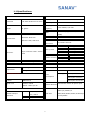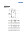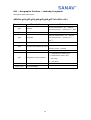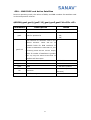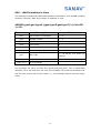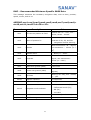
1
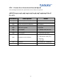
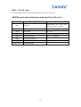
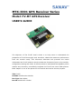
MTK-3301 GPS Receiver Series
Model: FV-M7 GPS Receiver
USER’S GUIDE
The objective of The FV-M7 User’s Guide is to help users to understand the
properties of FV-M7 thoroughly and, therefore, obtain the maximum performance
from the module easily. This document describes and provides the useful
information the FV-M7 module, which includes the functions of pins on the module,
configuration setting and utility. It will help users to understand the capability of the
module and, therefore, successfully integrate the FV-M7 into users’ GPS systems.
Each chapter is one of the pieces for the module and carries its own purpose.
Title FV-M7
Subtitle GPS Receiver Module
Doc Type Data Sheet
Doc Id GPS.FV-M7-070516
1
Contents
Chapter 1 Introduction ......................................................... 3
1.1 Specifications ............................................................................................4
Chapter 2 Pin Assignment .................................................... 5
2.1 Pin Assignment.........................................................................................5
2.2 Pin description ..........................................................................................6
Chapter 3 Operating GPS Locator Utility............................... 7
3.1 Connecting Com Port .............................................................................8
3.2
3.3
3.4
3.5
Functional
Functional
Functional
Functional
Windows
Windows
Windows
Windows
(Interval Setting) ...........................................9
(Local Time Zone Setting) ........................10
(SBAS Setting) .............................................. 11
(Power Mode Setting).................................12
3.6 Functional Windows (Restart Setting) ..........................................13
3.7 Functional Windows (View Default) ...............................................14
3.8 Using Mini GPS to Open Com Port ..................................................15
3.9 Using Mini GPS to Setup.....................................................................15
3.9 Using Mini GPS to Setup.....................................................................16
3.10 Using Mini GPS to Save Settings into Flash .............................17
Chapter 4 Available NMEA Messages .................................. 18
4.1 NMEA Protocol ........................................................................................18
Chapter 5 Limited Warranty ............................................... 26
2
Chapter 1 Introduction
The main goal of FV-M7 is to be used as a part of integrated system, which can be
a simple PVT (Position-Velocity-Time) system, for instance, G-mouse, PND
(Personal Navigation Device), or complex wireless systems, such as a system with
GSM function, a system with Bluetooth function, and a system with GPRS function.
The module (FV-M7) can be the best candidate for users’ systems as the users’
systems need the careful consideration on the performance, sensitivity, power
consumption, and/or size of the module. In the specification of FV-M7 at the next
page, it is noticeable that in addition to excellent start-up times and position
accuracy, the updated rate can be up to 5 Hz and the sensitivity of -158dbm.
If you have any technical questions, please contact us by either e-mail (prefer),
telephone or fax.
e-mail: [email protected]
Tel: 886-2-26879500
Fax: 886-2-26878893
When you send a request to us, please prepare the following information that may
help us to resolve your problem as soon as possible:
1. Serial No. of Product;
2. Type of antenna that is connected to the module;
3. Operating System (OS) of your host PC;
4. Simple description of your integrated system (may also included peripheral
connections and devices);
5. Describing the way you operate your system;
6. Description of failure by text, figure, or both;
7. Contact information, such as name, address, phone number, and e-mail
address.
3
1.1 Specifications
PHYSICAL CONSTRUCTION
Dimension
PERFORMANCE
GPS Chipset
MTK-3301
Sensitivity
-158dbm
L40.5mm*W35mm*H13.7mm
Receiving
1575.42MHZ; C/A code
Weight
frequency
11 grams
1 channel (Support WAAS, EGNOS,
SBAS
MSAS)
Standard: MCX Jack
DGPS
RF Connector
Optional: SMA, SMB Jack
RTCM Protocol
Receiver
32 parallel channels
architecture
Start-up time
Hot start
1 sec. typical
Warm start
35 sec. typical
Cold start
41sec. typical
Without aid
3.3 m CEP
DGPS (RTCM)
2.6 m
12pin connector with 1.27mm
Connector
pitch
Position accuracy
Construction
Full EMI Shielding
Velocity accuracy 0.1 Knot RMS steady state
ENVIRONMENTAL CONDITIONS
Operating: -30 ~ +80
Temperature
Storage: -40 ~ +85
℃
℃
COMMUNICATION
Update Rate
1 ~ 5Hz
Power Supply
3.3~5V +- 5%
Power
Acquisition
65mA
Tracking
50mA (first 5 minutes)
Consumption
Protocol
NMEA V3.01
Signal level
Default: RS232
48mA (after 5 minutes)
41mA (after 20 minutes)
GPS antenna with 2.8V power input
External Antenna
Option: UART @ 2.8V
INTERFACE CAPABILITY
4800 bps (default) &
Default
Standard Output
RMC, GGA, GSV*5,
Baud Rate
VTG, GSA*5
4800/9600/38400/57600/115200 bps
are adjustable
Sentences
Optional GLL, ZDA
4
Chapter 2 Pin Assignment
2.1 Pin Assignment
Figure 2.1 shows the pin definitions of FV-M7. Table 2.1 describes the corresponding
definitions for pins.
Figure 2.1 FV-M7 Pin definitions
5
2.2 Pin description
VIN (DC power input):
This is the main DC supply for a 3.3V ~ 5V +- 5% DC input power module board.
BATTERY (Backup battery):
This is the battery backup input that powers the SRAM and RTC when main power is removed.
Typical current draw is <10uA. Without an external backup battery, the module/engine board
will execute a cold star after every turn on. To achieve the faster start-up offered by a hot or
warm start, a battery backup must be connected. The battery voltage should be between
2.0v and 5.0v.
TIMEMARK (1PPS):
User can use this pin for special function.
For example, on/off LED
Output TTL level, 0V ~ 2.8V, 1PPS timemark output
TXA:
This is the main transmits channel for outputting navigation and measurement data to user’s
navigation software or user written software.
Output RS-232 level, 0V ~ 6V or Output TTL level, 0V ~ 2.8V
RXA:
This is the main receive channel for receiving software commands to the engine board from
MiniGPS or GPS Locator Utility (SV-3301) software or from user written software.
Input RS-232 level, 0V ~ 6V or Input TTL level, 0V ~ 2.8V
GND:
GND provides the ground for the engine board. Connect all grounds.
RXB:
This is mainly used to receive RTCM signals for differential purpose. Please note that a MTK
command must be sent to open this port first so that the RXB will receive the RTMC properly.
Input RS-232 level, 0V ~ 6V or Input TTL level, 0V ~ 2.8V
PBRES:
This pin provides active-low reset input to the GPS receiver module. It makes the GPS
receiver module to reset and search the GPS again.
6
Chapter 3 Operating GPS Locator Utility
GPS Locator Utility V2.61 is the latest utility for configuring the GPS settings of
Sanav GPS receivers. You can find the utility in the CD (FV-M7\Utility\Setup) and the
password is in License.txt. Double click on the Setup.exe and follow the installation
procedures.
GPS Locator Utility (Version 2.61), an application program for FV-M7, enables
you to do the configurations on the unit. Below are instructions of how to work with
this software, with assumption that you have successfully installed GPS Locator
Utility.
Mini GPS is an utility from MTK. If the users would like to read 32-channel, change
update rate (1 ~5Hz) and baud rate, please use Mini GPS.
7
3.1 Connecting Com Port
After selecting the Com Port, bard rate and Command Setting, click on “Connect”
and you will be able to do the configurations.
Select the ComPort
Select baud rate (default of 4800)
Select SV3310, which is the same as MTK-3301
8
3.2 Functional Windows (Interval Setting)
After connecting with success, you can view the NMEA data from different functional
windows. The configurations can be done in the “User Setting” window. On top of
the “User Setting” window, there are several taps. Please select the taps for
different settings.
User Setting Window, change GPS sentence output interval
Note:
After finishing interval setting, click “Send” to confirm the setting
before proceeding next tap window for the other setting.
Note:
If there is no backup power connected, all the settings will go back
to default after a power cycle.
9
3.3 Functional Windows (Local Time Zone Setting)
Different local time zones are available.
Note: After finishing local time zone setting, click “Send” to confirm the
setting before proceeding next tap window for the other setting.
Note:
If there is no backup power connected, all the settings will go back
to default after a power cycle.
10
3.4 Functional Windows (SBAS Setting)
Enable/Disable the SBAS (WAAS).
Note: After selecting the wanted SBAS setting, click “Send” to confirm the
setting before proceeding next tap window for the other setting.
Note:
If there is no backup power connected, all the settings will go back
to default after a power cycle.
11
3.5 Functional Windows (Power Mode Setting)
Select the power mode and “Continuous” is preferred. Please contact Sanav for
more information about the power mode.
Note: After selecting the wanted power mode setting, click “Send” to
confirm the setting before proceeding next tap window for the
other setting.
Note:
If there is no backup power connected, all the settings will go back
to default after a power cycle.
12
3.6 Functional Windows (Restart Setting)
User can restart the unit by using this utility.
Note: After selecting the wanted restart setting, click “Send” to confirm
the setting before proceeding next tap window for the other setting.
Note:
If there is no backup power connected, all the settings will go back
to default after a power cycle.
13
3.7 Functional Windows (View Default)
The default of receiver can be seen in this window.
14
3.8 Using Mini GPS to Open Com Port
Select the ComPort
Select baud rate (default of 4800)
15
3.9 Using Mini GPS to Setup
Setup
Test
Please note if the number of
percentage is over 100, all
setting can’t be allowed.
1.
Fix update rate can be changed from 1 ~ 5Hz
2.
Baud rate can be changed from 4800 ~ 115200 bps.
3.
When the settings are done, click on “Test” and follow the instruction in the next
page. You will be able to save the settings into the flash.
16
3.10 Using Mini GPS to Save Settings into Flash
Test
Set the setting and check the how
many times that can refresh the
module left.
FV series engine board module currently offers a function to refresh the firmware to
your desired setting like baud rate, updated rate or sentences output. Please
complete the setting at Chapter 3.9 then save the setting at this page by clicking
on the Set. The module is only allowed the user to refresh the module 7-8 times.
How many times remain, please see this information at the top of red box above.
Please note when the Setting write protection is marked, no matter how many
times left, the module won’t allow any setting of refreshing.
17
Chapter 4 Available NMEA Messages
4.1 NMEA Protocol
The NMEA protocol expresses the data in the format of ASCII. This is a standard
format for GPS applications.
4.1.1 Standard NMEA Messages
The module can output 7 standard NMEA messages, which are
NMEA Output Messages
NMEA Record
Description
GGA
Global Positioning System Fix Data.
GSA
GNSS DOP and Active Satellites
GSV
GNSS Satellites in View
RMC
Recommended Minimum Navigation Information
VTG
Course Over Ground and Ground Speed
GLL
Geographic Position – Latitude / Longitude
ZDA
Time & Date
Those messages are output at TX1 at the rate of 4800 bps (default setting). When
more than 4 messaged are chosen, a higher baud rate than 4800 bps is required.
The following will summarize the available NMEA messages. More information about
the NMEA messages refers to “NMEA 0183, Standard For Interfacing Marine
Electronic Devices, Version 3.01.
18
GGA – GPS Fix Data
Position fix related data, such as position, time, number of satellites in use, etc..
$GPGGA,gga1,gga2,gga3,gga4,gga5,gga6,gga7,gga8,gga9,g
ga10,gga11,gga12,gga13,gga14*hh<CR><LF>
Descriptions
Parameters
gga1
UTC time as position is fixed
Notes
hhmmss.sss: hh – hour; mm –
minute; ss.sss – second
ddmm.mmmmmm: dd – degree;
gga2
mm.mmmmmm – minute (0o ~
Latitude
90o)
gga3
Latitude sector
N – North; S - South
dddmm.mmmmmm: dd –
gga4
Longitude
degree; mm.mmmmmm –
minute (0o ~ 180o)
gga5
Longitude sector
E – East; W - West
0 – No fixed or invalid position
gga6
GPS quality indicator
1 – SPS Position available
2 – Differential GPS (SPS)
gga7
gga8
gga9
Number of SVs used in position xx: 00 ~ 12
estimation
HDOP
xx.xx: 00.00 ~ 99.99
Altitude above mean sea level xx.xxx: 00.000 ~ 99.999
(geoid)
gga10
Unit for Altitude
gga11
Geoidal separation
gga12
Unit for geoidal separation
gga13
Age of differential corrections
gga14
Reference station ID (DGPS)
xxxx: 0000 ~ 1023
Checksum
hex number (2 – character)
hh
<CR><LF>
M: meter
End of message
19
M: meter
unit : second; null when DGPS is
not used
GLL – Geographic Position – Latitude/Longitude
Navigation data and status.
$GPGLL,gll1,gll2,gll3,gll4,gll5,gll6,gll7*hh<CR><LF>
Parameters
Descriptions
gll1
Latitude
gll2
Latitude sector
Notes
ddmm.mmmmmm: dd – degree;
mm.mmmmmm – minute (0o ~ 90o)
N – North; S – South
dddmm.mmmmmm: dd – degree;
gll3
mm.mmmmmm – minute (0o ~
Longitude
180o)
gll4
Longitude sector
E – East; W – West
gll5
UTC time as position is fixed
gll6
Status for position fix
hhmmss.ss: hh – hour; mm –
minute; ss.ss – second
A – Valid; V – Invalid
A – Autonomous mode (fix);
gll7
Navigation mode indicator
D – Differential mode (fix);
E – DR (fix);
N – not valid
hh
<CR><LF>
Checksum
hex number (2 – character)
End of message
20
GSA – GNSS DOP and Active Satellites
Receiver operating mode, the values of DOPs, and PRN numbers for satellites used
in the GGA position solution.
$GPGSA,gsa1,gsa2,(gsa3*12),gsa4,gsa5,gsa6*hh<CR><LF>
Descriptions
Parameters
gsa1
Notes
Selection Mode
1 – fix not available;
gsa2
Mode for position fix
2 – 2D;
3 – 3D;
PRN numbers for satellites used in the xx
position solution. There will be 12
available fields for PRN numbers. If
gsa3*12
number of satellites is less than 12, the
remaining fields will be left as empty
fields. If number of satellites is greater
than 12, only the values of the first 12
satellites will be output.
gsa4
PDOP
0 ~ 99.99 in meters
gsa5
HDOP
0 ~ 99.99 in meters
gsa6
VDOP
0 ~ 99.99 in meters
hh
<CR><LF>
hex number (2 –
Checksum
character)
End of message
21
GSV – GNSS Satellites in View
This message indicates the observable satellites’ information, such as PRN numbers,
elevation, azimuth, SNR, and number of satellites in view.
$GPGSV,gsv1,gsv2,gsv3,((gsv4,gsv5,gsv6,gsv7)*n)*hh<CR
><LF>
Parameters
Descriptions
Notes
gsv1
Total number of messages
1~9
gsv2
Message number
1~9
gsv3
Total number of satellites in view
xx
gsv4
PRN number
xx
gsv5
Elevation (degrees)
90o maximum
gsv6
Azimuth (degrees)
0o ~ 360o
gsv7
SNR (C/N0)
hh
Checksum
<CR><LF>
0 ~ 99 dB-Hz, null when not
tracking
hex number (2 – character)
End of message
The message can carry at most four (gsv4,gsv5,gsv6,gsv7) sets of observable
satellites. For a less than four-set case, the message only transmits available sets
and the rest of them will not be output, i.e., the message doesn’t transmit empty
fields.
22
RMC – Recommended Minimum Specific GNSS Data
This message transmits the necessary navigation data, such as time, position,
speed, course, and so on.
$GPRMC,rmc1,rmc2,rmc3,rmc4,rmc5,rmc6,rmc7,rmc8,rmc9,r
mc10,rmc11,rmc12*hh<CR><LF>
Parameters
rmc1
Descriptions
UTC time as position is fixed
Notes
hhmmss.sss: hh – hour; mm –
minute; ss.sss – second
A – data valid, which includes the
rmc2
Status of position fix
scenarios of 2D, 3D, and DR.
V – navigation receiver warning
ddmm.mmmmmm: dd – degree;
rmc3
mm.mmmmmm – minute (0o ~
Latitude
90o)
rmc4
Latitude sector
N – North; S – South
dddmm.mmmmmm: ddd –
rmc5
Longitude
degree; mm.mmmmmm –
minute (0o ~ 180o)
rmc6
Longitude sector
E- East; W- West
rmc7
Speed over ground (SOG)
x.xxx knots
rmc8
Course over ground (COG)
rmc9
UTC Date
Referenced to true north (xx.xx
degrees)
ddmmyy: dd – day; mm – month;
yy – year
rmc10
Magnetic variation
Not supported
rmc11
Direction of magnetic variation
Not supported
A – Autonomous mode (fix);
rmc12
Navigation mode indicator
D – Differential mode (fix);
E – DR (fix);
N – not valid
hh
<CR><LF>
Checksum
hex number (2 – character)
End of message
23
VTG – Course Over Ground and Ground Speed
This message transmits the speed and course relative to ground.
$GPVTG,vtg1,vtg2,vtg3,vtg4,vtg5,vtg6,vtg7,vtg8,vtg9*hh<C
R><LF>
Descriptions
Parameters
Notes
vtg1
Course over ground (degrees)
Referenced to true north (xx.xxo)
vtg2
Indicator of course reference
T – true north
vtg3
Course over ground (degrees)
Not Support
vtg4
Indicator of course reference
M – magnetic north
vtg5
Speed over ground
x.xxx knots
vtg6
Unit of speed
N – nautical miles per hour
vtg7
Speed over ground
x.xxx km/hr
vtg8
Unit of speed
K – kilometers per hour
A – Autonomous mode (fix);
vtg9
Navigation mode indicator
D – Differential mode (fix);
E – DR (fix);
N – not valid
hh
<CR><LF>
Checksum
hex number (2 – character)
End of message
24
ZDA – Time & Date
This message transmits UTC time and date, and local time zone.
$GPZDA,zda1,zda2,zda3,zda4,zda5,zda6*hh<CR><LF>
Descriptions
Parameters
Notes
hhmmss.sss: hh – hour; mm –
zda1
UTC time
zda2
UTC day
01 ~ 31
zda3
UTC month
01 ~ 12
zda4
UTC year
xxxx (4 digits)
zda5
Local zone hours
00 to ± 13 hours
zda6
Local zone minutes
00 to ± 60 minutes
Checksum
hex number (2 – character)
hh
<CR><LF>
minute; ss.sss – second
End of message
25
Chapter 5 Limited Warranty
This unit can be used as part of navigational aids, and is not intended to replace other means of
navigation or aids. San Jose Navigation, Inc. warrants this GPS receiver and accessories to be free of
defect for a period of 12 months from the date of original purchase.
THIS WARRANTY APPLIES ONLY TO ORIGINAL PURCHASE.
In any event of a product defect while in normal usage, San Jose Navigation, Inc. will replace or repair
the defective product at no charge to the original the original purchaser for parts and labor. However,
San Jose Navigation, Inc. reserves the right of determination to replace or repair the defective product.
The replacement or repaired product will be warranted for a total of 90 days from the date of return
shipment, or for the remaining balance of the original warranty, whichever is longer.
PURCHASER DUTIES
The purchaser must return defective unit postpaid, with the proof of original purchase and a return
address to:
San Jose Navigation, Inc.
9F, No.105, Shi-Cheng Rd., Pan-Chiao City
Taipei Hsien, Taiwan, R.O.C. (220)
Tel: 886-2-26879500
Fax: 886-2-26878893
Website: http://www.sanav.com
Technical Support: [email protected]
26