1
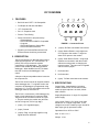
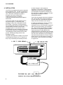
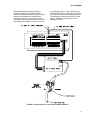
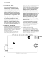
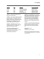
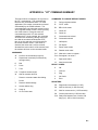
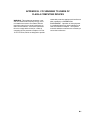
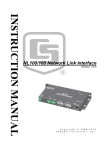
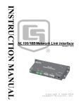
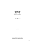
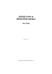
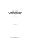
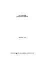
DC112 MODEM OPERATOR’S MANUAL REVISION: 12/91 COPYRIGHT 1987, 1989 CAMPBELL SCIENTIFIC, INC. WARRANTY AND ASSISTANCE The DC112 MODEM is warranted by CAMPBELL SCIENTIFIC, INC. to be free from defects in materials and workmanship under normal use and service for twelve (12) months from date of shipment unless specified otherwise. Batteries have no warranty. CAMPBELL SCIENTIFIC, INC.'s obligation under this warranty is limited to repairing or replacing (at CAMPBELL SCIENTIFIC, INC.'s option) defective products. The customer shall assume all costs of removing, reinstalling, and shipping defective products to CAMPBELL SCIENTIFIC, INC. CAMPBELL SCIENTIFIC, INC. will return such products by surface carrier prepaid. This warranty shall not apply to any CAMPBELL SCIENTIFIC, INC. products which have been subjected to modification, misuse, neglect, accidents of nature, or shipping damage. This warranty is in lieu of all other warranties, expressed or implied, including warranties of merchantability or fitness for a particular purpose. CAMPBELL SCIENTIFIC, INC. is not liable for special, indirect, incidental, or consequential damages. Products may not be returned without prior authorization. To obtain a Returned Materials Authorization (RMA), contact CAMPBELL SCIENTIFIC, INC., phone (435) 753-2342. After an applications engineer determines the nature of the problem, an RMA number will be issued. Please write this number clearly on the outside of the shipping container. CAMPBELL SCIENTIFIC's shipping address is: CAMPBELL SCIENTIFIC, INC. RMA#_____ 815 West 1800 North Logan, Utah 84321-1784 CAMPBELL SCIENTIFIC, INC. does not accept collect calls. Non-warranty products returned for repair should be accompanied by a purchase order to cover the repair. 815 W. 1800 N. Logan, UT 84321-1784 USA Phone (435) 753-2342 FAX (435) 750-9540 www.campbellsci.com Campbell Scientific Canada Corp. 11564 -149th Street Edmonton, Alberta T5M 1W7 CANADA Phone (403) 454-2505 FAX (403) 454-2655 Campbell Scientific Ltd. Campbell Park 80 Hathern Road Shepshed, Leics. LE12 9RP ENGLAND Phone (44)-50960-1141 FAX (44)-50960-1091 DC112 MODEM 1. FEATURES • Bell 212A and CCITT V.22 Compatible • Full Duplex at 300 and 1200 Baud • "AT" Command Set • RJ-11C Telephone Jack • Pulse or Tone Dialing • Direct Connection to and powered by: - CSI dataloggers - CSI PC201 Card in IBM PC Compatible - Computer - CSI PC203 Power-up Control Box - CSI SC532 RS232 Interface • Signal Level Connects/Disconnects 5Vdc External Power minimizing current drain 2. DESCRIPTION The DC112 Modem is a 300/1200 baud modem employing the popular "AT" command set. Its primary use is as a remote site modem connected to a CSI datalogger. The modem is powered and enabled by the battery-powered datalogger. When disabled, the DC112 draws less than 2 uA from the datalogger 5 Vdc output. FIGURE 1. Connector Pinout 4. (output) Rx Data- serial data from modem. 5. (input) Modem Enable- a logic high turns on 5V power to the modem. A logic low shuts off 5V power to the modem. 6. (input) Serial Device Enable - a logic high disables communication with the modem without removing power or changing the modem's mode. This input can be negated with an internal jumper. 7. No Connection 8. No Connection A Hayes or Hayes compatible modem is used at the computer site. The DC112 can be used as an originate modem at the datalogger site. To originate a call to the computer, the datalogger is programmed using Instruction 97. For more information refer to the datalogger manual, Instruction 97. The DC112 is connected to a CSI datalogger by using a 9-pin subminiature D connector cable. The pinout of the connector is shown in Figure 1. The pins used by the modem are (all levels are OV for logic low, 5V for logic high): 1. (input) +5 V regulated supply 2. (input) Ground 3. (output) Ring- a logic high signifies a ring signal has been detected. 9. (input) Tx Data- serial data to the modem. 3. SPECIFICATIONS Current Drain: Approximately 2 uA when modem enable is low; 35 mA when modem enable is high but phone is on-hook; 48 mA when off-hook. Supply Requirements: A single 5 V regulated power supply. Logic Levels: Below 1.5 V inputs a low state and above 3.5 V inputs a high state. A low voltage level on the Tx data input (pin 9) and Rx data output (pin 4) represents a mark. Operational from -25oC to +50oC Size: 4 3/8" x 3" x 1" Weight: 12 oz. 1 DC112 MODEM 4. INSTALLATION Your DC112 is designed to be used on standard device telephone lines. The DC112 connects to the telephone line by means of a USOC RJ11C jack. Connection to telephone companyprovided coin service (central office implemented systems) is prohibited. Connection to party lines service is subject to State tariffs. Connect the cable from the telephone jack to the modem Figure 2. Connection to the datalogger is done with a Campbell Scientific SC12 Cable. Connect the 14 awg grounding wire (provided with the DC112) to the grounding terminal (GND) on the DC112 and to the datalogger ground. If the enclosure has a grounded bus bar, then connect the ground wire to the bus bar instead of the datalogger ground. The datalogger ground should be tied to earth ground. See the grounding section of the datalogger manual. The goal of the telephone company is to provide you with the best service it can. In order to do this, it may occasionally be necessary for them to make changes in their equipment, operations, or procedures. If these changes might affect your service or the operation of your equipment, the telephone company will give you notice, in writing, to allow you to make any changes necessary to maintain uninterrupted service. If you have any questions about your telephone line, such as how many pieces of equipment you can connect to it, the telephone company will provide this information upon request. In certain circumstances, it may be necessary for the telephone company to request information from you concerning the equipment which you have connected to your telephone line. Upon request of the telephone company, provide the FCC registration number and the ringer equivalence number (REN) of the equipment which is connected to your line; both of these items are listed on the equipment label. The sum of all of the REN's on your telephone lines should be less than five in order to assure proper service from the telephone company. In some cases, a sum of five may not be usable on a given line. FIGURE 2. RJ11C Phone Modem Connections 2 DC112 MODEM Remote datalogger installations require a telephone surge protector (Model 2372-01) unless the telephone company confirms a surge protector has already been installed at the remote site (Figure 3). Connect the 14 awg grounding wire (provided with the DC112) to the grounding terminal (GND) on the DC112 and to the datalogger ground. If the enclosure has a grounded bus bar, then connect the ground wire to the bus bar instead of the datalogger ground. The datalogger ground should be tied to earth ground. See the grounding section of the datalogger manual. FIGURE 3. Burial Phone Line to Remote Telephone Modem 3 DC112 MODEM 5. IF PROBLEMS ARISE If any of your telephone equipment is not operating properly, you should immediately remove it from your telephone line, as it may cause harm to the telephone network. If the telephone company notes a problem, they may temporarily discontinue service. When practical, they will notify you in advance of this disconnection. If advance notice is not feasible, you will be notified as soon as possible. When you are notified, you will be given the opportunity to correct the problem and informed of your right to file a complaint with the FCC. For assistance in installation or for repair, telephone (801) 753-2342 or write to Campbell Scientific, Inc., P.O. Box 551, Logan, Utah 84321. To comply with FCC Rules and Regulations, all repairs on the DC112 Modem will be performed by Campbell Scientific, Inc. or an authorized agent of Campbell Scientific, Inc. 6. THEORY OF OPERATION The DC112 modem is used to transmit data over bandwidth-limited channels such as telephone lines by modulating audio tones, using Frequency Shift Keying (FSK) at 300 baud, or Phase Shift Keying (PSK) at 1200 baud. The telephone company gives a 40 to 150 VRMS, 20 Hz signal on the phone lines to signify a ring, which is typically on for 2 seconds and off for 4 seconds. The ring detection circuitry is continuously powered but draws less than 2 uA. The ring signal is passed on to the datalogger through an opto-coupler. The datalogger responds by raising the Modem Enable line which enables the 5Vdc power to the modem. The modem then answers and remains off-hook until it loses the carrier or the datalogger lowers the Modem Enable line. The datalogger lowers the Modem Enable line by remote command or after 40 seconds in the absence of a command. When the Modem Enable line goes low, the 5Vdc power is removed from the modem circuitry, dropping power to the off-hook relay and thus placing the phone line on-hook. To reject noise common to both phone lines and to satisfy registration requirements, the modem circuitry is electrically isolated from the phone lines by using an opto-isolator and coupling transformer. 6.1 JUMPER CONFIGURATION The DC112 has 5 user-changeable jumpers; one at location C8 and four at location H15 as shown in Figure 4. As shipped, only one jumper is in place, H15 1 to 8. The following table lists the jumper meanings. After removing a jumper, store it on a single pin of the terminal. FIGURE 4. Jumper Locations 4 DC112 MODEM TABLE 1. Jumper Settings JUMPER PINS MEANING FACTORY SETTING 1. H15 2. H15 3. H15 4. H15 5. C8 1 to 8 2 to 7 3 to 6 4 to 5 1 to 2 Result Codes Enabled Auto-Answer Disabled Enable CCITT V.22 Do not use Non-datalogger Site Jumper in Place Jumper not in Place Jumper not in Place Jumper not in Place Jumper not in Place JUMPER 1 - Result codes (Appendix A) are sent to your terminal screen. JUMPER 2 - Auto answer is disabled by putting the jumper in place. This option is used only when the modem is not to answer a call. For example: The DC112 is connected to a phone line which is to be used part time for voice communication. In this situation it is best to have the datalogger call the computer. JUMPER 3 - Selects Bell 212A (U.S. and Canada) or CCITT V.22 (Foreign). This does not mean that the DC112 is tested and approved for all foreign countries. CCITT is an international consultative committee that sets international communications usage standards. V.22 is a standard that the DC112 meets for communicating at 1200 baud. JUMPER 5 - Non datalogger site. This option when enabled keeps the printer enable line from disabling the transmit data line. This option is provided because of the CR10 datalogger's ability to synchronously address peripherals connected to the 9 pin port (CR10 Manual, Section 6.2). This Jumper is only used when the DC112 is used as originate modem at the computer. Jumpers 1, 2, and 3 determine the state of the modem when power is switched on by Modem Enable or the ATZ command is executed. Other functions which are fixed by hardware are: Numeric Result Codes Full Duplex Command Characters Echoed Both the jumper selectable and fixed functions can be changed by appropriate "AT" commands (see Appendix A). 5 APPENDIX A. "AT" COMMAND SUMMARY This manual does not attempt to be a primer on the "AT" command set. The commands are therefore only summarized below. For most applications, the modem commands are issued automatically by the PC208 software. The commands apply only when the modem is used as an originate modem, which is not the primary use of this modem. Except as noted, all commands begin with "AT" and end with carriage return. As an example, the command ATDT5551212 followed by carriage return will tone dial the number that follows the ATDT, then go on-line and wait up to 30 seconds for the remote modem carrier. If the carrier is detected, the result code 1 will be returned, otherwise the result code 3 will be returned, and the modem will return to the command mode. COMMANDS: COMMANDS TO CHANGE DEFAULT MODES: R Call an originate modem B CCITT mode B1 BELL 212A mode C Carrier off C1 Carrier on E Commands not echoed E1 Commands echoed F Half duplex F1 Full duplex Q Return result codes Q1 Disable result codes Sr? What is the value in register r AT Prefix to all commands (except /A) Sr=n Set register r to value n A/ Repeat last command (not followed by carriage return) V Digit result codes D Dial V1 Word result codes P Pulse T Tone 0..9 Telephone number digits W Wait for another dial tone ; Return to command state after dialing , Pause Z Reset to default settings A Answer without ring H Hang up O Go to on-line state RESULT CODES: 0 OK 1 Connect 2 Ring 3 No Carrier 4 Error REGISTERS: S0 Rings before auto-answer (0..255) S6 Wait for dial tone (2..255 seconds) S7 Wait for remote carrier (1..255 seconds) S8 Comma pause time (0..255 seconds) S10 Delay time between loss of carrier and hang up (1..255 in 10th of seconds) A-1 APPENDIX B. FCC WARNING TO USERS OF CLASS A COMPUTING DEVICES WARNING: This equipment generates, uses, and can radiate radio frequency energy, and if not installed and used in accordance with the instruction manual, may cause interference to radio communications. It has been tested and found to comply with the limits for a Class A computing device pursuant to Subpart J of Part 15 of FCC Rules, which are designed to provide reasonable protection against such interference when operated in a COMMERCIAL ENVIRONMENT. Operation of this equipment in a residential area may cause interference to radio and television reception. The operator must take whatever measures are necessary to correct the interference. B-1