1
AQUAZONE™
50PTH, PTV, PTD026-072
Two-Stage Water Source Heat Pumps
with PURON® Refrigerant (R-410A)
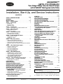
Installation, Start-Up, and Service Instructions
CONTENTS
Page
SAFETY CONSIDERATIONS . . . . . . . . . . . . . . . . . . . . .1,2
GENERAL . . . . . . . . . . . . . . . . . . . . . . . . . . . . . . . . . . . . . . . . 2
INSTALLATION . . . . . . . . . . . . . . . . . . . . . . . . . . . . . . . . 2-29
Step 1 — Check Jobsite . . . . . . . . . . . . . . . . . . . . . . . . . . 2
Step 2 — Check Unit . . . . . . . . . . . . . . . . . . . . . . . . . . . . . 2
• STORAGE
• PROTECTION
• INSPECT UNIT
Step 3 — Locate Unit. . . . . . . . . . . . . . . . . . . . . . . . . . . . . 8
• FIELD CONVERSION OF DISCHARGE AIR
Step 4 — Mount the Unit . . . . . . . . . . . . . . . . . . . . . . . . . 9
• HORIZONTAL UNIT
• VERTICAL UNITS
Step 5 — Check Duct System . . . . . . . . . . . . . . . . . . . . 9
• SOUND ATTENUATION
• EXISTING DUCT SYSTEM
Step 6 — Install Condensate Drain . . . . . . . . . . . . . . . 9
• HORIZONTAL UNIT
• VERTICAL UNITS
• VENTING
Step 7 — Pipe Connections . . . . . . . . . . . . . . . . . . . . . 10
• WATER LOOP APPLICATIONS
• GROUND-WATER APPLICATIONS
• GROUND-LOOP APPLICATIONS
• INSTALLATION OF SUPPLY AND RETURN HOSE
KIT
Step 8 — Wire Field Power Supply . . . . . . . . . . . . . . 12
• POWER CONNECTION
• SUPPLY VOLTAGE
• 208-VOLT OPERATION
• 460-VOLT OPERATION
• WSHP OPEN WIRING
Step 9 — Wire Field Controls. . . . . . . . . . . . . . . . . . . . 25
• THERMOSTAT CONNECTIONS
• WATER FREEZE PROTECTION
• AIR COIL FREEZE PROTECTION
• ACCESSORY CONNECTIONS
• WATER SOLENOID VALVES
Step 10 — Operate ECM Interface Board . . . . . . . . 27
• STANDALONE — NO DDC CONTROLS
• WSHP OPEN CONTROLS
PRE-START-UP . . . . . . . . . . . . . . . . . . . . . . . . . . . . . . . .29,30
System Checkout . . . . . . . . . . . . . . . . . . . . . . . . . . . . . . . 29
FIELD SELECTABLE INPUTS. . . . . . . . . . . . . . . . . 30-33
Complete C Control Jumper Settings. . . . . . . . . . . . 30
Deluxe D Control Jumper Settings . . . . . . . . . . . . . . 30
Complete C Control DIP Switches . . . . . . . . . . . . . . . 30
Deluxe D Control DIP Switches. . . . . . . . . . . . . . . . . . 30
Units with Modulating Hot Water Reheat
(HWR) Option . . . . . . . . . . . . . . . . . . . . . . . . . . . . . . . . . 31
• STANDALONE — NO DDC CONTROLS
• WSHP OPEN CONTROLS
• HWR APPLICATION CONSIDERATIONS
• HWR COMPONENT FUNCTIONS
Deluxe D Control Accessory
Relay Configurations . . . . . . . . . . . . . . . . . . . . . . . . . 32
Page
START-UP . . . . . . . . . . . . . . . . . . . . . . . . . . . . . . . . . . . . 33-38
Operating Limits . . . . . . . . . . . . . . . . . . . . . . . . . . . . . . . . 33
Scroll Compressor Rotation. . . . . . . . . . . . . . . . . . . . . 34
Unit Start-Up Cooling Mode . . . . . . . . . . . . . . . . . . . . . 34
Unit Start-Up Heating Mode . . . . . . . . . . . . . . . . . . . . . 34
Unit Start-Up with WSHP Open Controls . . . . . . . . 36
Flow Regulation. . . . . . . . . . . . . . . . . . . . . . . . . . . . . . . . . 37
Flushing . . . . . . . . . . . . . . . . . . . . . . . . . . . . . . . . . . . . . . . . 37
Antifreeze . . . . . . . . . . . . . . . . . . . . . . . . . . . . . . . . . . . . . . . 37
Cooling Tower/Boiler Systems . . . . . . . . . . . . . . . . . . 38
Ground Coupled, Closed Loop and Plateframe
Heat Exchanger Well Systems . . . . . . . . . . . . . . . . 38
OPERATION. . . . . . . . . . . . . . . . . . . . . . . . . . . . . . . . . . 38-42
Power Up Mode . . . . . . . . . . . . . . . . . . . . . . . . . . . . . . . . . 39
Units with Aquazone™ Complete C Control . . . . . 39
Units with Aquazone Deluxe D Control . . . . . . . . . . 39
Units with WSHP Open Multiple Protocol. . . . . . . . 39
COMPLETE C AND DELUXE D BOARD
SYSTEM TEST . . . . . . . . . . . . . . . . . . . . . . . . . . . . . .42,43
Test Mode . . . . . . . . . . . . . . . . . . . . . . . . . . . . . . . . . . . . . . . 42
WSHP Open Test Mode. . . . . . . . . . . . . . . . . . . . . . . . . . 43
Retry Mode. . . . . . . . . . . . . . . . . . . . . . . . . . . . . . . . . . . . . . 43
Aquazone Deluxe D Control LED Indicators . . . . . 43
SERVICE . . . . . . . . . . . . . . . . . . . . . . . . . . . . . . . . . . . . . .44,45
Filters . . . . . . . . . . . . . . . . . . . . . . . . . . . . . . . . . . . . . . . . . . . 44
Water Coil . . . . . . . . . . . . . . . . . . . . . . . . . . . . . . . . . . . . . . . 44
Condensate Drain Pans . . . . . . . . . . . . . . . . . . . . . . . . . 44
Refrigerant System. . . . . . . . . . . . . . . . . . . . . . . . . . . . . . 44
Compressor. . . . . . . . . . . . . . . . . . . . . . . . . . . . . . . . . . . . . 44
Fan Motors . . . . . . . . . . . . . . . . . . . . . . . . . . . . . . . . . . . . . . 44
Condensate Drain Cleaning . . . . . . . . . . . . . . . . . . . . . 44
Air Coil Cleaning . . . . . . . . . . . . . . . . . . . . . . . . . . . . . . . . 44
Condenser Cleaning . . . . . . . . . . . . . . . . . . . . . . . . . . . . 44
Checking System Charge . . . . . . . . . . . . . . . . . . . . . . . 45
Refrigerant Charging. . . . . . . . . . . . . . . . . . . . . . . . . . . . 45
Air Coil Fan Motor Removal . . . . . . . . . . . . . . . . . . . . . 45
Replacing the WSHP Open Controller’s
Battery . . . . . . . . . . . . . . . . . . . . . . . . . . . . . . . . . . . . . . . . 45
TROUBLESHOOTING . . . . . . . . . . . . . . . . . . . . . . . . 45-53
Thermistor . . . . . . . . . . . . . . . . . . . . . . . . . . . . . . . . . . . . . . 45
Control Sensors . . . . . . . . . . . . . . . . . . . . . . . . . . . . . . . . . . . 45
WSHP Open Controller . . . . . . . . . . . . . . . . . . . . . . . . . . . . 46
Thermostatic Expansion Valves . . . . . . . . . . . . . . . . . . 46
Stopped or Malfunctioned ECM Motor . . . . . . . . . . . . 50
Moisture Check. . . . . . . . . . . . . . . . . . . . . . . . . . . . . . . . . . . . 51
APPENDIX A — WSHP OPEN SCREEN
CONFIGURATION . . . . . . . . . . . . . . . . . . . . . . . . . . 54-59
50PTH,PTV,PTD START-UP
CHECKLIST . . . . . . . . . . . . . . . . . . . . . . . . . . CL-1, CL-2
IMPORTANT: Read the entire instruction manual before
starting installation.
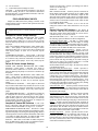
SAFETY CONSIDERATIONS
Installation and servicing of air-conditioning equipment can
be hazardous due to system pressure and electrical
Manufacturer reserves the right to discontinue, or change at any time, specifications or designs without notice and without incurring obligations.
Catalog No. 04-53500079-01
Printed in U.S.A.
Form 50PT-4SI
Pg 1
7-10
Replaces: 50PT-3SI
components. Only trained and qualified service personnel
should
install, repair, or service air-conditioning equipment.
Untrained personnel can perform basic maintenance functions such as cleaning coils and filters and replacing filters. All
other operations should be performed by trained service
personnel. When working on air-conditioning equipment, observe precautions in the literature, tags and labels attached to
the unit, and other safety precautions that may apply.
Improper installation, adjustment, alteration, service, maintenance, or use can cause explosion, fire, electrical shock or
other conditions which may cause personal injury or property
damage. Consult a qualified installer, service agency, or a local
distributor or branch for information or assistance. The
qualified installer or agency must use factory-authorized kits or
accessories when modifying this product. Refer to the individual instructions packaged with the kits or accessories when
installing.
Follow all safety codes. Wear safety glasses and work
gloves. Use quenching cloth for brazing operations. Have fire
extinguisher available. Read these instructions thoroughly and
follow all warnings or cautions attached to the unit. Consult
local building codes and the National Electrical Code (NEC)
for special installation requirements.
Understand the signal words — DANGER, WARNING,
and CAUTION. DANGER identifies the most serious hazards
which will result in severe personal injury or death.
WARNING signifies hazards that could result in personal injury or death. CAUTION is used to identify unsafe practices,
which would result in minor personal injury or product and
property damage.
Recognize safety information. This is the safety-alert
symbol ( ). When this symbol is displayed on the unit and in
instructions or manuals, be alert to the potential for personal
injury.
unit start-up, read all manuals and become familiar with the
unit and its operation. Thoroughly check out the system before
operation. Complete the inspections and instructions listed
below to prepare a unit for installation. See Table 1 for unit
physical data.
IMPORTANT: This equipment is designed for indoor
installation ONLY. Extreme variations in temperature,
humidity and corrosive water or air will adversely affect
the unit performance, reliability and service life.
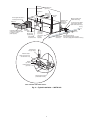
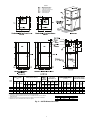
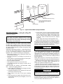
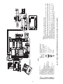
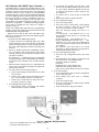
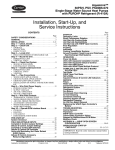
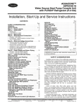
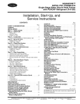
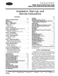
HORIZONTAL UNIT (50PTH) — Horizontal units are designed for indoor installation only. Be sure to allow adequate space
around the unit for servicing. See Fig. 1 for overall unit dimensions. Refer to Fig. 2 for an illustration of a typical horizontal
installation.
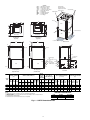
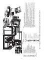
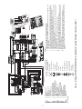
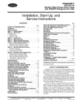
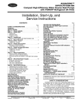
VERTICAL AND DOWNFLOW UNITS (50PTV, PTD) —
Vertical units are designed for indoor installations. While vertical units are typically installed in a floor-level closet or a small
mechanical room, the unit access guidelines for these units are
very similar to those described for horizontal units. See Fig. 3
and 4 for overall dimensions. Refer to Fig. 5 for an example of
a typical vertical installation. Refer to Fig. 6 for a sample
downflow installation.
CAUTION
To avoid equipment damage, do not use these units as a
source of heating or cooling during the construction process. The mechanical components and filters used in these
units quickly become clogged with construction dirt and
debris which may cause system damage.
Step 2 — Check Unit — Upon receipt of shipment at
the jobsite, carefully check the shipment against the bill of
lading. Make sure all units have been received. Inspect the carton or crating of each unit, and inspect each unit for damage.
Ensure the shipping company makes proper notation of any
shortages or damage on all copies of the freight bill. Concealed
damage not discovered during unloading must be reported to
the shipping company within 15 days of receipt of shipment.
NOTE: It is the responsibility of the purchaser to file all
necessary claims with the shipping company.
1. Be sure that the location chosen for unit installation provides ambient temperatures maintained above freezing.
Well water applications are especially susceptible to
freezing.
2. Be sure the installation location is isolated from sleeping
areas, private offices and other acoustically sensitive
spaces.
NOTE: A sound control accessory package may be used
to help eliminate sound in sensitive spaces.
3. Check local codes to be sure a secondary drain pan is not
required under the unit.
4. Be sure unit is mounted at a height sufficient to provide
an adequate slope of the condensate lines. If an appropriate slope cannot be achieved, a field-supplied condensate
pump may be required.
5. Provide sufficient space for duct connection. Do not
allow the weight of the ductwork to rest on the unit.
6. Provide adequate clearance for filter replacement and
drain pan cleaning. Do not allow piping, conduit, etc. to
block filter access.
7. Provide sufficient access to allow maintenance and
servicing of the fan and fan motor, compressor and coils.
Removal of the entire unit from the closet should not be
necessary.
WARNING
Electrical shock can cause personal injury or death. Before
installing or servicing system, always turn off main power
to system. There may be more than one disconnect switch.
Turn off accessory heater power if applicable.
GENERAL
This installation and start-up instructions literature is for
Aquazone™ two-stage water source heat pump systems.
Water source heat pumps (WSHPs) are single-package horizontally and vertically mounted units with electronic controls
designed for year-round cooling and heating. Aquazone
WSHPs are available in the following unit configurations:
• 50PTH unit with horizontal airflow and right, left or back
discharge
• 50PTV unit with vertical airflow and top discharge
• 50PTD unit with vertical airflow and bottom discharge
(downflow)
IMPORTANT: The installation of water source heat pump
units and all associated components, parts, and accessories
which make up the installation shall be in accordance with
the regulations of ALL authorities having jurisdiction and
MUST conform to all applicable codes. It is the responsibility of the installing contractor to determine and comply
with ALL applicable codes and regulations.
INSTALLATION
Step 1 — Check Jobsite — Installation, operation and
maintenance instructions are provided with each unit. Before
2
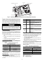
INSPECT UNIT — To prepare the unit for installation, complete the procedures listed below:
1. Compare the electrical data on the unit nameplate with
ordering and shipping information to verify that the
correct unit has been shipped.
2. Do not remove the packaging until the unit is ready for
installation.
3. Verify that the unit’s refrigerant tubing is free of kinks or
dents, and that it does not touch other unit components.
4. Inspect all electrical connections. Be sure connections are
clean and tight at their terminations.
5. Loosen compressor bolts until the compressor rides freely
on springs. Remove shipping restraints.
6. Remove the four 1/4 in. shipping bolts from compressor
support plate (two bolts on each side) to maximize vibration and sound alternation.
8. Provide an unobstructed path to the unit within the closet
or mechanical room. Space should be sufficient to allow
removal of unit if necessary.
9. Provide ready access to water valves and fittings, and
screwdriver access to unit side panels, discharge collar,
and all electrical connections.
10. Where access to side panels is limited, pre-removal of the
control box side mounting screws may be necessary for
future servicing.
STORAGE — If the equipment is not needed immediately at
the jobsite, it should be left in its shipping carton and stored in a
clean, dry area of the building or in a warehouse. Units must be
stored in an upright position at all times. If carton stacking is
necessary, stack units a maximum of 3 high. Do not remove
any equipment from its shipping package until it is needed for
installation.
PROTECTION — Once the units are properly positioned on
the jobsite, cover them with either a shipping carton, vinyl film,
or an equivalent protective covering. Cap open ends of pipes
stored on the jobsite. This precaution is especially important in
areas where painting, plastering, or spraying of fireproof material, etc. is not yet complete. Foreign material that accumulates
within the units can prevent proper start-up and necessitate
costly clean-up operations.
Before installing any of the system components, be sure to
examine each pipe, fitting, and valve, and remove any dirt or
foreign material found in or on these components.
CAUTION
Failure to remove shipping brackets from spring-mounted
compressors will cause excessive noise and could cause
component failure due to added vibration.
7. Remove any blower support cardboard from inlet of the
blower.
8. Locate and verify any accessory kit located in compressor
and/or blower section.
9. Remove any access panel screws that may be difficult to
remove once unit is installed.
CAUTION
DO NOT store or install units in corrosive environments or
in locations subject to temperature or humidity extremes
(e.g., attics, garages, rooftops, etc.). Corrosive conditions
and high temperature or humidity can significantly reduce
performance, reliability, and service life. Always move
units in an upright position. Tilting units on their sides may
cause equipment damage.
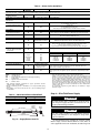
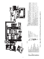
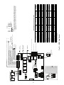
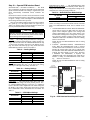
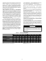
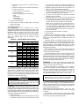
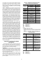
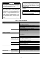
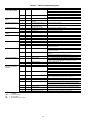
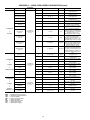
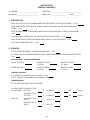
Table 1 — Physical Data — 50PTH, PTV, PTD026-072 Units
UNIT 50PTH, PTV, PTD
COMPRESSOR (1 each)
FACTORY CHARGE R-410A (oz)
ECM FAN MOTOR AND BLOWER
Fan Motor Type
Fan Motor (Hp)
Blower Wheel Size (D x W) (in.)
COAXIAL COIL VOLUME (gal.)
WATER CONNECTION SIZE (FPT) (in.)
HWG CONNECTION SIZE (FPT) (in.)
VERTICAL
Air Coil
Dimensions (H x W) (in.)
Filter Standard — 1-in. Throwaway
(Qty — Size) (in.)
Weight (lb)
Operating
Packaged
HORIZONTAL
Air Coil
Dimensions (H x W) (in.)
Filter Standard — 1-in. Throwaway
(Qty — Size) (in.)
Weight (lb)
Operating
Packaged
026
038
064
072
78
049
Two-Stage, Scroll
81
58
144
156
VAR
1/
2
9x7
.76
3/
4
1/
2
VAR
1/
2
11 x 10
.92
3/
4
1/
2
VAR
1
11x10
1.24
1
1/
2
VAR
1
11x10
1.56
1
1/
2
VAR
1
11x10
1.56
1
1/
2
36 x 25
1 — 16 x 30
1 — 20 x 30
36 x 25
1 — 16 x 30
1 — 20 x 30
443
453
443
453
28 x 20
28 x 25
32 x 25
1 — 28 x 24
1 — 28 x 30
2 — 16 x 30
266
276
327
337
416
426
18 x 31
20 x 25
1 — 12 x 20
1 — 20 x 24
20 x 40
1 — 18 x 20
1 — 20 x 24
327
337
416
426
2 — 18 x 18
266
276
LEGEND
ECM — Electronically Commutated Motor
HWG — Hot Water Generator
VAR — Variable Speed
NOTE: All units have spring compressor mountings, TXV (thermostatic expansion valve) expansion devices, and 1/2 and 3/4-in. electrical knockouts.
3
20 x 45
20 x 45
2 — 20 x 24
2 — 20 x 24
443
453
443
453
LEGEND
CSP
Front
2 Service Access
—
—
—
—
—
—
—
Alternate Service Panel
Blower Service Panel
Control Access Panel
Compressor Service Panel
Female Pipe Thread
Hot Water Generator
Hot Water Reheat
Power Supply
3/4” Knockout
Left Return
ASP
1.6”
L
G
K
E F
CAP
J
H
Right
Discharge
H
Left
Discharge
D
A
Air Coil Side
Condensate
Back
3/4” FPT
Discharge
Blower
Outlet
Condensate
3/4” FPT
Back
Discharge
Size
Y
C
Front
BSP
O
CSP
3.25”
Low Voltage
1/2” Knockout
P
2 Service Access
2 Service Access
Right Return
1/2”
Knockout
3.25”
Q
Front
Z
C
, 072
Air Coil Side
2 Service
Access
ASP
BSP
CAP
CSP
FPT
HWG
HWR
P
R
Blower
Outlet
O
BSP
Q
R
A
A
X
Y Configuration - Left Return/Back Discharge
P Configuration - Right Return/Back Discharge - Air Coil Opening
P
M
N
Blower
Outlet
ASP
Right
View
O
BSP
P
BSP
CSP
Blower
Outlet
O
Left
View
N
Front
M
W Configuration - Left Return/Right Discharge - Air Coil Opening
V
Air Coil
S
U
N Configuration - Right Return/Left Discharge - Air Coil Opening
Air Coil
1.1”
S
CSP
C T
C
Front
ASP
T
Front
B
B
N Configuration - Right Return/Left Discharge - Air Coil Opening
W Configuration - Left Return/Right Discharge - Air Coil Opening
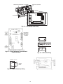
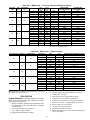
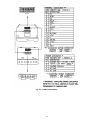
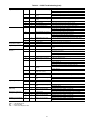
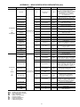
OVERALL CABINET
(in.)
50PTH
UNIT
026
038
049
064,072
WATER CONNECTIONS (in.)
1
A
Width
22.4
25.4
25.4
25.4
B
C
Depth Height
62.2
71.2
76.2
81.2
19.3
21.3
21.3
21.3
D
In
2.1
3.4
3.4
3.4
2
Right
View
3
F
E
Out HWG
In
10.0 13.9
10.8 14.6
10.8 15.6
10.8 15.6
WATER
CONNECTIONS (in.)
- UNITS
WITH HWR
ELECTRICAL
KNOCKOUTS (in.)
DISCHARGE CONNECTIONS (in.) RETURN CONNECTION
DUCT FLANGE INSTALLED
USING AIR COIL
( 0.10 in.)
OPENING (in.)
J
K
L
1/ -in. 1/ -in. 3/ -in.
1
2
Loop
2
2
4
O
P
Q
S
T
Cond Cond Cond M
Water HWG
(LH N Supply Supply (RH R Return Return U V
FPT FPT
G
H
(in.) Loop Loop Low
rtn)
Height Width rtn)
Width Height
Ext
Power
(in.)
HWG Condin D out E Voltage Pump Supply
Out ensate
3/
1/
16.9
3.5
2.1
10.0
3.6
6.1
8.6
3.6 2.0 12.5
15.5 3.6 2.0 33.8
16.2 2.3 1.5
4
2
3/
1/
18.9
3.4
5.96 13.13 3.4
6.1
8.6
3.1 1.2 19.0
17.5 3.1 1.0 34.8
18.2 3.1 1.5
4
2
1/
18.9
3.4
1
5.96 13.13 3.6
6.1
8.6
3.1 1.2 19.0
17.5 3.1 1.0 39.8
18.2 3.1 1.5
2
1/
18.9
3.4
1
5.96 13.13 3.6
6.1
8.6
3.1 1.2 19.0
17.5 3.1 1.0 44.8
18.2 3.1 1.5
2
4
5
AIRFLOW CONFIGURATION
NOTES:
1. Condensate connection is stainless steel 3/4 in. female pipe thread (FPT).
2. Unit shipped with top and bottom filter rack and is not suitable for duct connection without
additional support.
3. Discharge flange is factory-installed.
4. Hanger kit is factory-installed.
5. Shaded areas are recommended service areas, not required.
6. Discharge can be modified in field. Return cannot be modified.
CODE
N
P
W
Y
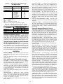
Fig. 1 — 50PTH026-072 Dimensional Data
4
RETURN
Right
Right
Left
Left
DISCHARGE
Left
Back
Right
Back
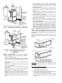
3/8” threaded rods
(by others)
Filter Access
Return Air
(Ductwork
not shown)
Field-supplied transition to
minimize pressure loss
Thermostat
Wiring
Power Wiring
Stainless steel
braid hose
with integral
“J” swivel
Supply Air
Balancing Valve (fieldinstalled accessory)
Low Pressure Drop Water
Control Valve (optional)
(field-installed accessory)
Unit Power
Insulated supply duct with
at least one 90 degree elbow
to reduce air noise
(field-supplied)
Building
Loop
Flexible
Connection
Unit Power
Disconnect
(by others)
Field-Supplied
Electric Heat
(if applicable)
Aux Electric
Heat Disconnect
Water Out
Water In
Unit Hanger
(factorysupplied)
(field-installed
accessory)
3/8” Threaded
Rod (by others)
Vibration Isolator
(white-compressor end
and red-blower end)
Washer
(by others)
Double Hex Nuts
(by others)
Integral hanger supportpre-attached in factory
UNIT HANGER ISOLATION DETAIL
Fig. 2 — Typical Installation — 50PTH Unit
5
Ball Valve with optional
integral P/Tplug (typical for supply
and return piping) (field-installed accessory)
LEGEND
ASP
BSP
CAP
CSP
FPT
HV
HWG
HWR
LV
—
—
—
—
—
—
—
—
—
Alternate Service Panel
Blower Service Panel
Control Access Panel
Compressor Service Panel
Female Pipe Thread
High Voltage
Hot Water Generator
Hot Water Reheat
Low Voltage
Field-Installed
Discharge Flange
(shipped loose inside
blower section)
Access Panels
Filter Bracket
Air Coil
ASP
P
BSP
Front
N
Front
O
B
N
P
O
A
2ʼ Service Access
ASP
CSP
Q
K - Configuration - Right Return
/Top Discharge
(Top View)
CAP
M
Air Coil Side
Air Coil Side
J - Configuration - Left Return
/Top Discharge
(Top View)
S
2ʼ Service Access
S
R
R
Isometric View
1.00”
U
U
Air Coil
Air Coil
T
T
1.68”
C
C
1.18”
CSP
ASP
Condensate
3/4” FPT
Power Supply
3/4”
HV Knockout
1/2”
Knockout
Low Voltage
1/2”
LV Knockout
CAP
1.63”
G
CSP
Back
Front
Back
K - Configuration - Right Return Air Coil Opening
Front
J - Configuration - Left Return Air Coil Opening
(Right Side View)
A
B
C
Width Depth Height
026
038
049
064,
072
22.4
25.4
25.4
25.4
25.6
30.6
30.6
30.6
48.5
50.5
54.5
58.5
K
E
D
H
Front View
(Left Side View)
OVERALL CABINET
(in.)
50PTV
UNIT
J
F
L
WATER CONNECTIONS (in.)
1
2
D
In
E
Out
2.1
3.4
3.4
3.4
10.0
10.8
10.8
10.8
WATER
CONNECTIONS (in.)
- UNITS
WITH HWR
ELECTRICAL
KNOCKOUTS (in.)
DISCHARGE CONNECTIONS (in.)
RETURN CONNECTION
DUCT FLANGE INSTALLED
USING AIR COIL OPENING
( 0.10 in.)
(in.)
J
K
L
1/ -in. 1/ -in. 3/ -in.
1
2
Loop
2
2
4
Cond Cond Cond
Water HWG
FPT FPT
F
G
H
(in.) Loop Loop Low
Ext
Power
HWG HWG Cond- (in.)
in D out E Voltage Pump Supply
In
Out ensate
3/
1/
2.1 10.0
3.6
6.1
8.6
13.9 16.9
7.8
4
2
3/
1/
15.6 18.9
7.8
5.96 13.13
3.6
6.1
8.6
4
2
1/
15.6 18.9
7.8
1
5.96 13.13
3.6
6.1
8.6
2
1/
15.6 18.9
7.8
1
5.96 13.13
3.6
6.1
8.6
2
3
4
5
M
(LH
rtn)
N
7.2
6.4
6.4
6.4
5.8
6.3
6.3
6.3
O
P
Q
Supply Supply (RH
Width Depth rtn)
14.0
18.0
18.0
18.0
14.0
18.0
18.0
18.0
4.9
5.3
5.3
5.3
R
2.2
2.2
2.2
2.2
S
T
Return Return
Depth Height
21.1
26.1
26.1
26.1
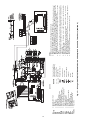
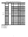
AIRFLOW CONFIGURATION
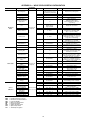
NOTES:
1. Condensate connection is stainless steel 3/4 in. female pipe thread (FPT).
2. Unit shipped with top and bottom filter rack and is not suitable for duct connection without
additional support.
3. Discharge flange is field-installed.
4. Shaded areas are recommended service areas, not required.
CODE
J
K
Fig. 3 — 50PTV Dimensional Data
6
RETURN
Left
Right
DISCHARGE
Top
Top
27.2
27.2
31.2
35.2
U
1.0
1.0
1.0
1.0
LEGEND
ASP
BSP
CAP
CSP
FPT
HWG
HWR
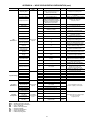
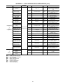
OVERALL CABINET
(in.)
50PTD
UNIT
1
A
Width
026
038
049
064,072
WATER CONNECTIONS (in.)
22.4
25.4
25.4
25.4
B
C
Depth Height
25.6
30.6
30.6
30.6
52.5
54.5
58.5
62.5
2
D
In
E
Out
2.1
3.4
3.4
3.4
10.0
10.8
10.8
10.8
3
F
HWG
In
13.9
15.6
15.6
15.6
4
G
HWG
Out
16.9
18.9
18.9
18.9
5
—
—
—
—
—
—
—
Alternate Service Panel
Blower Service Panel
Control Access Panel
Compressor Service Panel
Female Pipe Thread
Hot Water Generator
Hot Water Reheat
WATER
CONNECTIONS (in.)
- UNITS
WITH HWR
1
Loop
Water HWG
FPT
FPT (in.)
H
Loop
Cond- (in.)
in D
ensate
3
1
3.6
/4
/2 2.1
3/
1/
3.6
5.96
4
2
1/
3.6
1
5.96
2
1/
3.6
1
5.96
2
DISCHARGE CONNECTIONS (in.) RETURN CONNECTION (in.)
DUCT FLANGE INSTALLED
USING AIR COIL OPENING
( 0.10 in.)
ELECTRICAL
KNOCKOUTS (in.)
J
2-in.
Cond
1/
2
Loop Low
out E Voltage
10.0
13.13
13.13
13.13
3.6
3.6
3.6
3.6
Cond
K
L
4-in.
Cond
Ext
Pump
Power
Supply
6.1
6.1
6.1
6.1
8.6
8.6
8.6
8.6
1/ -in.
2
3/
M
(LH
rtn)
N
6.7
7.2
7.2
7.2
8.4
9.0
9.0
9.0
O
P
Supply Supply
Width Depth
10.1
13.4
13.4
13.4
9.1
12.9
12.9
12.9
Q
(RH
rtn)
R
S
Return
Depth
T
Return
Height
U
10.8
10.4
10.4
10.4
2.2
2.2
2.2
2.2
21.1
26.1
26.1
26.1
27.2
27.2
31.4
35.2
1.0
1.0
1.0
1.0
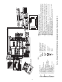
AIRFLOW CONFIGURATION
NOTES:
1. Condensate connection is stainless steel 3/4 in. female pipe thread (FPT).
2. Unit shipped with top and bottom filter rack and is not suitable for duct connection without
additional support.
3. Downflow unit does not have discharge flange, and is rated for zero clearance installation.
4. Shaded areas are recommended service areas, not required.
CODE
J
K
Fig. 4 — 50PTD Dimensional Data
7
RETURN
Left
Right
DISCHARGE
Bottom
Bottom
• Provide adequate clearance for filter replacement and
drain pan cleaning. Do not block filter access with piping, conduit or other materials. Refer to Fig. 1, 3, and 4
for dimensional data.
• Provide access for fan and fan motor maintenance and
for servicing the compressor and coils without removing
the unit.
• Provide an unobstructed path to the unit within the closet
or mechanical room. Space should be sufficient to allow
removal of the unit, if necessary.
• In limited side access installations, pre-removal of the
control box side mounting screws will allow control box
removal for future servicing.
• Provide access to water valves and fittings and screwdriver access to the unit side panels, discharge collar and
all electrical connections.
NOTE: Correct placement of the horizontal unit can play an
important part in minimizing sound problems. Since ductwork is normally applied to these units, the unit can be
placed so that the principal sound emission is outside the occupied space in sound-critical applications. A fire damper
may be required by the local code if a fire wall is penetrated.
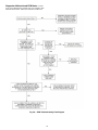
FIELD CONVERSION OF DISCHARGE AIR — The discharge air of the 50PTH horizontal units can be converted
between side and back discharge in the field. The conversion
process is the same for right and left return configurations. See
Fig. 7 and 8.
NOTE: It is not possible to convert return air between left or
right return models in the field due to refrigerant piping
changes.
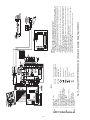
Supply Air
Building
Loop
Flexible
Connection
Return
Air
Water
Out
Water
In
Stainless steel
braid hose
with integral
“J” swivel
(field-installed
accessory)
Power
Thermostat
Wiring
Compressor
Access Panel
Balancing Valve
(field-installed
accessory)
Low Pressure
Drop Water
Control Valve
(optional)
(field-installed
accessory)
Ball Valve with optional
integral P/T plug
(typical for supply and
return piping) (field-Installed
accessory)
NOTE: Ball valve with integral pressure temperature plug recommended.
Fig. 5 — Typical Vertical Installation — 50PTV Unit
Flexible
Connection
Return
Air
Power
Thermostat
Wiring
Compressor
Access Panel
Building
Loop
Water
Out
Stainless
steel
braid hose
with
integral ”J”
swivel(fieldinstalled
accessory)
Water
In
Balancing Valve
(field-installed
accessory)
Low Pressure
Drop Water
Control Valve
(optional)
(field-installed
accessory)
Water
Connection End
Return Air
Supply
Duct
Ball Valve with
optional integral
Flexible
P/T plug (typical for
Connection
supply and return
piping)(field-installed
Supply Air
accessory)
Side Discharge
Water
Connection End
NOTE: Ball valve with integral pressure temperature plug recommended.
Fig. 6 — Typical Downflow Installation —
50PTD Unit
Return Air
Step 3 — Locate Unit — The following guidelines
should be considered when choosing a location for a WSHP:
• Units are for indoor use only.
• Locate in areas where ambient temperatures are between
39 F and 102 F and relative humidity is no greater than
75%.
• Provide sufficient space for water, electrical and duct
connections.
• Locate unit in an area that allows easy access and removal
of filter and access panels.
• Allow enough space for service personnel to perform
maintenance.
• Return air must be able to freely enter the space if unit needs
to be installed in a confined area such as a closet.
• Install the unit on a piece of rubber, neoprene or other
mounting pad material for sound isolation. The pad
should be at least 3/8 in. [10 mm] to 1/2 in. [13 mm] in
thickness. Extend the pad beyond all four edges of the
unit.
Drain
Discharge Air
Back Discharge
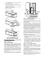
Fig. 7 — Conversion Right Return,
Side Discharge to Back Discharge
Preparation — The unit should be on the ground in a well lit
area. Hung units should be taken down to ground level before
converting.
Side to Back Discharge Conversion
1. Remove screws to free the top and discharge panels. Set
screws aside for later use. See Fig. 8.
2. Remove the access panel and set aside.
3. Lift the discharge panel from side of unit and rotate it to
back using care not to damage blower wiring.
4. Check blower wire routing and connections for undue
tension or contact with sheet metal edges. Re-route if
necessary.
8
5. Check refrigerant tubing for contact with other components. Adjust if necessary.
6. Reinstall top panel using screws set aside in Step 1.
NOTE: Location for some screws at bottom of discharge
panel may have to be changed.
7. Manually spin fan wheel to check for obstructions.
Adjust for any obstruction found.
8. Replace access panel.
Water
Connection End
Remove Screws
Return Air
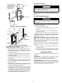
Fig. 9 — 50PTV Units Mounted With
Vibration Absorption Pad
Side Discharge
Water
Connection End
Step 5 — Check Duct System — Size the duct sys-
tem to handle the design airflow quietly.
Rotate
NOTE: Depending on the unit, the fan wheel may have a shipping support installed at the factory. This must be removed
before operating unit.
SOUND ATTENUATION — To eliminate the transfer of
vibration to the duct system, a flexible connector is recommended for both discharge and return air duct connections on
metal duct systems. The supply and return plenums should include internal duct liner of fiberglass or be made of duct board
construction to maximize sound attenuation of the blower.
Installing the WSHP unit to uninsulated ductwork in an unconditioned space is not recommended since it will sweat and
adversely affect the unit’s performance.
To reduce air noise, at least one 90-degree elbow could be
included in the supply and return air ducts, provided system
performance is not adversely impacted. The blower speed can
also be changed in the field to reduce air noise or excessive airflow, provided system performance is not adversely impacted.
EXISTING DUCT SYSTEM — If the unit is connected to
existing ductwork, consider the following:
• Verify that the existing ducts have the proper capacity to
handle the unit airflow. If the ductwork is too small, install
larger ductwork.
• Check existing ductwork for leaks and repair as necessary.
NOTE: Local codes may require ventilation air to enter the
space for proper indoor air quality. Hard-duct ventilation
may be required for the ventilating air supply. If hard
ducted ventilation is not required, be sure that a proper air
path is provided for ventilation air to unit to meet ventilation requirement of the space.
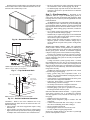
Return Air
Move to Side
Water
Connection End
Replace Screws
Return Air
Drain
Back Discharge
Discharge Air
Fig. 8 — Conversion Left Return,
Side Discharge to Back Discharge
Back to Side Discharge Conversion — Follow instructions
above for Side to Back Discharge Conversion, noting the
panels would be reversed.
Step 4 — Mount the Unit
HORIZONTAL UNIT (50PTH) — Horizontal units should
be mounted using the factory-installed hangers. Proper attachment of hanging rods to building structure is critical for safety.
See Fig. 1. Rod attachments must be able to support the weight
of the unit. See Table 1 for unit operating weights.
VERTICAL UNITS (50PTV,PTD) — Vertical and downflow
units are available in left or right return air configurations. See
Fig. 3 and 4. Mount the unit (except 50PTD) on a vibration
absorption pad slightly larger than the entire base to minimize
vibration transmission. It is not necessary to mount the unit on
the floor. See Fig. 9.
NOTE: Some codes require the use of a secondary drain pan
under vertical units. Check local codes for more information.
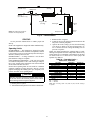
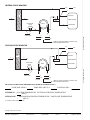
Step 6 — Install Condensate Drain
HORIZONTAL UNIT (50PTH) — Slope the unit toward the
drain at 1/4 in. See Fig. 10. If it is not possible to meet the required pitch, install a condensate at the unit to pump condensate to building drain.
Horizontal units are not internally trapped, therefore an external trap is necessary. Install each unit with its own individual
trap and means to flush or blow out the condensate drain line.
Do not install units with a common trap or vent. See Fig. 11 for
typical condensate connections.
NOTE: Never use a pipe size smaller than the connection.
VERTICAL UNITS (50PTV,PTD) — Each unit uses a condensate hose inside all cabinets as a trapping loop, therefore an
external trap is not necessary. See Fig. 12.
9
• Be sure to support the line where anticipated sagging from
the condensate or when “double trapping” may occur.
• If condensate pump is present on unit, be sure drain connections have a check valve to prevent back flow of condensate
into other units.
Each unit must be installed with its own individual vent and
means to flush or blow out the condensate drain line. Do not install units with a common trap or vent.
Step 7 — Pipe Connections — Depending on the
application, there are 3 types of WSHP piping systems to
choose from: water loop, ground-water and ground loop. Refer
to Piping Section of Carrier System Design Manual for additional information.
All WSHP units use low temperature soldered female pipe
thread fittings for water connections to prevent annealing and
out-of-round leak problems which are typically associated with
high temperature brazed connections. Refer to Table 1 for connection sizes. When making piping connections, consider the
following:
• Use a backup wrench when making screw connections to
unit to prevent internal damage to piping.
• Insulation may be required on piping to avoid condensation
in the case where fluid in loop piping operates at temperatures below dew point of adjacent air.
• Piping systems that contain steel pipes or fittings may be
subject to galvanic corrosion. Dielectric fittings may be
used to isolate the steel parts of the system to avoid galvanic
corrosion.
WATER LOOP APPLICATIONS — Water loop applications
usually include a number of units plumbed to a common piping system. Maintenance to any of these units can introduce air
into the piping system. Therefore, air elimination equipment
comprises a major portion of the mechanical room plumbing.
The flow rate is usually set between 2.25 and 3.5 gpm per
ton of cooling capacity. For proper maintenance and servicing,
pressure-temperature (P/T) ports are necessary for temperature
and flow verification.
Cooling tower/boiler systems typically utilize a common
loop maintained at 60 to 95 F. The use of a closed circuit evaporative cooling tower with a secondary heat exchange between
the tower and the water loop is recommended. If an open type
cooling tower is used continuously, chemical treatment and filtering will be necessary.
In addition to complying with any applicable codes, consider the following for system piping:
• Piping systems using water temperatures below 50 F
require 1/2-in. closed cell insulation on all piping surfaces to
eliminate condensation.
• Avoid all plastic to metal threaded fittings due to the potential to leak. Use a flange fitted substitute.
• Teflon tape thread sealant is recommended to minimize
internal fouling of the heat exchanger.
• Use backup wrench. Do not overtighten connections.
• Route piping to avoid service access areas to unit.
• Flush the piping system prior to operation to remove dirt
and foreign materials from the system.
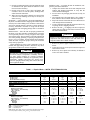
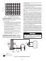
GROUND-WATER APPLICATIONS — Typical groundwater piping is shown in Fig. 13. In addition to complying
with any applicable codes, consider the following for system piping:
• Install shut-off valves for servicing.
• Install pressure-temperature plugs to measure flow and
temperature.
• Connect boiler drains and other valves using a “T” connector to allow acid flushing for the heat exchanger.
• Do not overtighten connections.
• Route piping to avoid service access areas to unit.
• Use PVC SCH80 or copper piping material.
NOTE: PVC SCH40 should not be used due to system high
pressure and temperature extremes.
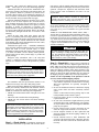
1/4” Pitch for
Drainage
Pitch Toward
Drain
Drain Connection
Fig. 10 — Horizontal Unit Pitch
NOTE: Trap should be deep enough to offset maximum unit static
difference. A 4-in. trap is recommended.
Fig. 11 — Trap Condensate Drain
3/4” Copper FPT/PVC
3/4” PVC
Vent
1/2”
1/4” per foot
slope to drain
1/2”
Water
Connections
Alternate
Condensate
Location
NOTE: Unit does not need to be sloped toward drain.
Fig. 12 — Vertical Condensate Connection
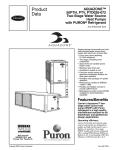
VENTING — Install a vent in the condensate line of any
application that may allow dirt or air to collect in the line. Consider the following:
• Always install a vent where an application requires a long
horizontal run.
• Always install a vent where large units are working against
higher external static pressure and to allow proper drainage
for multiple units connected to the same condensate main.
10
Water
Control
Valve
(field-installed
accessory)
Flow
Regulator
(field-installed
accessory)
Pressure
Tank
Water Out
Water In
From Pump
Shut-Off
Valve (field-installed accessory)
Boiler
Drains
(field-installed)
Strainer (field-installed accessory)
(16 to 20 mesh recommended for
filter sediment)
Fig. 13 — Typical Ground-Water Piping Installation
5. Refer to Table 3. Do not exceed the minimum bend radius
for the hose selected. Exceeding the minimum bend radius may cause the hose to collapse, which reduces water
flow rate. Install an angle adapter to avoid sharp bends
in the hose when the radius falls below the required
minimum.
NOTE: Piping must comply with all applicable codes.
Insulation is not required on loop water piping except where
the piping runs through unheated areas or outside the building
or when the loop water temperature is below the minimum expected dew point of the pipe ambient. Insulation is required if
loop water temperature drops below the dew point.
Water Supply and Quantity — Check water supply. Water
supply should be plentiful and of good quality. See Table 2 for
water quality guidelines.
IMPORTANT: Failure to comply with the above required
water quality and quantity limitations and the closedsystem application design requirements may cause damage
to the tube-in-tube heat exchanger. This damage is not the
responsibility of the manufacturer.
In all applications, the quality of the water circulated
through the heat exchanger must fall within the ranges listed in
the Water Quality Guidelines table. Consult a local water treatment firm, independent testing facility, or local water authority
for specific recommendations to maintain water quality within
the published limits.
GROUND-LOOP APPLICATIONS — Temperatures between
25 and 110 F and a cooling capacity of 2.25 to 3 gpm of flow
per ton is recommended. In addition to complying with any
applicable codes, consider the following for system piping:
• Limit piping materials to only polyethylene fusion in the
buried sections of the loop.
• Do not use galvanized or steel fittings at any time due to
corrosion.
• Avoid all plastic to metal threaded fittings due to the potential to leak. Use a flange fitted substitute.
• Do not overtighten connections.
• Route piping to avoid service access areas to unit.
• Use pressure-temperature (P/T) plugs to measure flow of
pressure drop.
INSTALLATION OF SUPPLY AND RETURN HOSE
KIT — Follow these piping guidelines.
1. Install a drain valve at the base of each supply and return
riser to facilitate system flushing.
2. Install shutoff/balancing valves and unions at each unit to
permit unit removal for servicing.
3. Place strainers at the inlet of each system circulating
pump.
4. Select the proper hose length to allow slack between connection points. Hoses may vary in length by +2% to –4%
under pressure.
CAUTION
Do not bend or kink supply lines or hoses.
Pipe joint compound is not necessary when Teflon threaded
tape is pre-applied to hose assemblies or when flared-end
connections are used. If pipe joint compound is preferred, use
compound only in small amounts on the male pipe threads of
the fitting adapters. Prevent sealant from reaching the flared
surfaces of the joint.
NOTE: When anti-freeze is used in the loop, assure that it is
compatible with Teflon tape or pipe joint compound employed.
Maximum allowable torque for brass fittings is 30 ft-lb. If a
torque wrench is not available, tighten finger-tight plus one
quarter turn. Tighten steel fittings as necessary.
Optional pressure-rated hose assemblies designed specifically for use with Carrier units are available. Similar hoses can
be obtained from alternate suppliers. Supply and return hoses
are fitted with swivel-joint fittings at one end to prevent kinking during installation.
CAUTION
Backup wrench is required when tightening water connections to prevent water line damage.
Refer to Fig. 14 for an illustration of a supply/return hose
kit. Male adapters secure hose assemblies to the unit and risers.
Install hose assemblies properly and check them regularly to
avoid system failure and reduced service life.
11
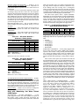
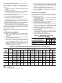
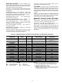
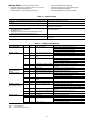
Table 2 — Water Quality Guidelines
HX
CLOSED RECIRCULATING†
OPEN LOOP AND RECIRCULATING WELL**
MATERIAL*
Scaling Potential — Primary Measurement
Above the given limits, scaling is likely to occur. Scaling indexes should be calculated using the limits below.
pH/Calcium
All
N/A
pH < 7.5 and Ca Hardness, <100 ppm
Hardness Method
Index Limits for Probable Scaling Situations (Operation outside these limits is not recommended.)
Scaling indexes should be calculated at 150 F for direct use and HWG applications, and at 90 F for indirect HX use. A monitoring plan should be
implemented.
Ryznar Stability Index
6.0 - 7.5
All
N/A
If >7.5 minimize steel pipe use.
Langelier Saturation Index
–0.5 to +0.5
All
N/A
If <–0.5 minimize steel pipe use.
Based upon 150 F HWG and direct well, 85 F indirect well HX.
Iron Fouling
<0.2 ppm (Ferrous)
Iron Fe2+ (Ferrous)
All
N/A
(Bacterial Iron Potential)
If Fe2+ (ferrous) >0.2 ppm with pH 6 - 8, O2<5 ppm check for iron bacteria.
Iron Fouling
<0.5 ppm of Oxygen
All
N/A
Above this level deposition will occur.
Corrosion Prevention††
pH
6 - 8.5
6 - 8.5
All
Monitor/treat as needed.
Minimize steel pipe below 7 and no open tanks with pH <8.
<0.5 ppm
Hydrogen Sulfide (H2S)
At H2S>0.2 ppm, avoid use of copper and cupronickel piping or HXs.
All
N/A
Rotten egg smell appears at 0.5 ppm level.
Copper alloy (bronze or brass) cast components are okay to <0.5 ppm.
<0.5 ppm
Ammonia Ion as Hydroxide,
Chloride, Nitrate and Sulfate
All
N/A
Compounds
Maximum Chloride Levels
Maximum allowable at maximum water temperature.
50 F (10 C)
75 F (24 C)
100 F (38 C)
Copper
N/A
<20 ppm
NR
NR
Cupronickel
N/A
<150 ppm
NR
NR
304 SS
N/A
<400 ppm
<250 ppm
<150 ppm
316 SS
N/A
<1000 ppm
<550 ppm
<375 ppm
Titanium
N/A
>1000 ppm
>550 ppm
>375 ppm
Erosion and Clogging
Particulate Size and Erosion
<10 ppm of particles and a <10 ppm (<1 ppm “sandfree” for reinjection) of particles and a maximum velocity
maximum velocity of 6 fps. of 6 fps. Filtered for maximum 800 micron size. Any particulate that is not
All
Filtered for maximum
removed can potentially clog components.
800 micron size.
Brackish
Use cupronickel heat exchanger when concentrations of calcium or sodium chloAll
N/A
ride are greater than 125 ppm are present. (Seawater is approximately 25,000
ppm.)
CONDITION
HWG —
HX
—
N/A —
NR
SS
—
—
††If the concentration of these corrosives exceeds the maximum allowable
level, then the potential for serious corrosion problems exists.
Sulfides in the water quickly oxidize when exposed to air, requiring that no
agitation occur as the sample is taken. Unless tested immediately at the
site, the sample will require stabilization with a few drops of one Molar zinc
acetate solution, allowing accurate sulfide determination up to 24 hours
after sampling. A low pH and high alkalinity cause system problems, even
when both values are within ranges shown. The term pH refers to the acidity, basicity, or neutrality of the water supply. Below 7.0, the water is considered to be acidic. Above 7.0, water is considered to be basic. Neutral water
contains a pH of 7.0.
To convert ppm to grains per gallon, divide by 17. Hardness in mg/l is
equivalent to ppm.
LEGEND
Hot Water Generator
Heat Exchanger
Design Limits Not Applicable Considering Recirculating
Potable Water
Application Not Recommended
Stainless Steel
*Heat exchanger materials considered are copper, cupronickel, 304 SS
(stainless steel), 316 SS, titanium.
†Closed recirculating system is identified by a closed pressurized piping
system.
**Recirculating open wells should observe the open recirculating design
considerations.
Step 8 — Wire Field Power Supply
Table 3 — Metal Hose Minimum Bend Radii
HOSE DIAMETER (in.)
1/
2
MINIMUM BEND RADII (in.)
21/2
3/
4
4
1
51/2
Rib Crimped
Swivel
Brass
Fitting
WARNING
To avoid possible injury or death due to electrical shock,
open the power supply disconnect switch and secure it in
an open position during installation.
Brass
Fitting
CAUTION
Use only copper conductors for field-installed electrical
wiring. Unit terminals are not designed to accept other
types of conductors.
Length
(2 ft Length Standard)
MPT
Fig. 14 — Supply/Return Hose Kit
All field-installed wiring, including the electrical ground,
MUST comply with the National Electrical Code (NEC) as
well as applicable local codes. In addition, all field wiring must
12
conform to the Class II temperature limitations described in the
NEC.
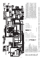
Refer to unit wiring diagrams Fig. 15-24 for a schematic of
the field connections, which must be made by the installing (or
electrical) contractor. For Deluxe D with WSHP Open controls
3-phase units and Complete C with Open controls single-phase
and 3-phase units contact Application Engineering. Refer to
Table 4 for fuse sizes.
Consult the unit wiring diagram located on the inside of the
compressor access panel to ensure proper electrical hookup.
The installing (or electrical) contractor must make the field
connections when using field-supplied disconnect.
Operating voltage must be the same voltage and phase as
shown in electrical data shown in Table 4.
Make all final electrical connections with a length of flexible conduit to minimize vibration and sound transmission to
the building.
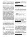
POWER CONNECTION — Make line voltage connection
by connecting the incoming line voltage wires to the line
side of the compressor contactor terminal as shown in
Fig. 25. See Table 4 for amperage ratings to provide correct
wire and maximum overcurrent protection sizing.
SUPPLY VOLTAGE — Operating voltage to unit must be
within voltage range indicated on unit nameplate.
On 3-phase units, voltages under load between phases must
be balanced within 2%. Use the following formula to determine the percentage voltage imbalance:
% Voltage Imbalance
= 100 x
452 + 464 + 455
3
1371
=
3
Average Voltage =
= 457
Determine maximum deviation from average voltage:
(AB) 457 – 452 = 5 v
(BC) 464 – 457 = 7 v
(AC) 457 – 455 = 2 v
Maximum deviation is 7 v.
Determine percent voltage imbalance.
% Voltage Imbalance = 100 x
7
457
= 1.53%
This amount of phase imbalance is satisfactory as it is
below the maximum allowable 2%.
Operation on improper line voltage or excessive phase
imbalance constitutes abuse and may cause damage to electrical components.
NOTE: If more than 2% voltage imbalance is present, contact
your local electric utility.
208-VOLT OPERATION — All 208-230 volt units are factory
wired for 208 volts. The transformers may be switched to
230-volt operation by switching the red (208 volt) wire with
the orange (230 volt) wire at the L1 terminal.
460-VOLT OPERATION — Units using 460-v and an ECM
(electronically commutated motor) fan motor, modulating
HWR, and/or internal secondary pump will require a neutral
wire from the supply side in order to feed accessory with
265-v.
max voltage deviation from average voltage
average voltage
Example: Supply voltage is 460-3-60.
AB = 452 volts
BC = 464 volts
AC = 455 volts
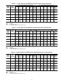
Table 4 — 50PTH,PTV,PTD Electrical Data
50PTH,
PTV, PTD
UNITS
026
038
049
064
072
FLA
HACR
LRA
RLA
HWR
—
—
—
—
—
COMPRESSOR
V-PH-Hz*
VOLTAGE
MIN/MAX
RLA
208/230-1-60
208/230-1-60
208/230-3-60
460-3-60
208/230-1-60
208/230-3-60
460-3-60
208/230-1-60
208/230-3-60
460-3-60
208/230-1-60
197/254
197/254
197/254
414/506
197/254
197/254
414/506
197/254
197/254
414/506
197/254
10.3
16.7
11.2
4.5
21.2
13.5
6.4
25.6
17.6
9.0
27.2
LRA
FAN
MOTOR
FLA
TOTAL
UNIT FLA
MIN
CIRCUIT
AMPS
MAX
FUSE/
HACR
52.0
82.0
58.0
29.0
96.0
88.0
41.0
118.0
123.0
62.0
150.0
4.3
4.3
4.3
4.1
7.0
7.0
6.9
7.0
7.0
6.9
7.0
14.6
21.0
15.5
8.6
28.2
20.5
13.3
32.6
24.6
15.9
34.2
17.2
25.2
18.3
9.7
33.5
23.9
14.9
39.0
29.0
18.2
41.0
25
40
25
15
50
35
20
60
45
25
60
LEGEND
Full Load Amps
Heating, Air Conditioning and Refrigeration
Locked Rotor Amps
Rated Load Amps
Hot Water Reheat
REHEAT
PUMP
FLA
0.8
0.8
0.8
0.7
1.07
1.07
1.07
1.07
1.07
1.07
1.07
UNITS WITH HWR
TOTAL
MIN
UNIT
CIRCUIT
FLA
AMP
15.4
18.0
21.8
26.0
16.3
19.1
9.3
10.4
29.3
34.6
21.6
24.9
14.4
16.0
33.7
40.1
25.7
30.1
17.7
19.2
35.3
42.1
MAX
FUSE/
HACR
25
40
30
15
50
35
20
60
45
25
60
*The 460-v units using an ECM (electronically commutated motor) fan
motor, modulating HWR, and/or an internal secondary pump will require
a neutral wire from the supply side in order to feed the accessory with
265-v.
13
14
AL
ASTAT
BM
BR
CB
CC
CO
DTS
ECM
FP1
FP2
HP
HWG
JW1
LOC
MV
NEC
P1
RVS
TRANS
—
—
—
—
—
—
—
—
—
—
—
—
—
—
—
—
—
—
—
—
Wire Nut
Ground
Thermistor
Temperature Switch
Solenoid Coil
Condensate Pan
Relay/Contactor Coil
Field Line Voltage Wiring
Field Low Voltage Wiring
Printed Circuit Trace
Optional Wiring
C
TB1
Y2 Y1 G O W C R DH AL1 A
CFM
A
AL1
DEHUM
S1
SW1
SW2
SW3
SW4
SW5
SW6
SW7
SW8
SW9
OFF ON
J1
BM ECM
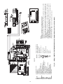
NOTES:
1. Compressor and blower motor thermally protected internally.
2. All wiring to the unit must comply with NEC and local codes.
3. Transformer for 208/230 v will be connected for 208 v operation. For 230 v operation, disconnect RED lead at L1 and attach ORN lead to L1. Insulate open end of RED lead. Transformer for 220/240 v will be connected for 220 v operation. For 240 v operation, disconnect
RED lead at L1 and attach ORN lead to L1. Transformer is energy limiting or may have circuit breaker.
4. FP1 thermistor provides freeze protection for water. When using antifreeze solutions, cut
JW3 jumper.
5. Typical Aquazone™ thermostat wiring shown. Refer to thermostat installation instructions
for wiring to the unit. Thermostat wiring must be Class 1 and voltage rating equal to or
greater than unit supply voltage.
6. 24-v alarm signal shown. For dry alarm contact, cut JW1 jumper and dry contact will be
available between AL1 and AL2.
7. Transformer secondary ground via Complete C board standoffs and screws to control box.
(Ground available from top two standoffs as shown.)
8. Aquastat is field-supplied and must be wired in series with the hot leg to the pump. Aquastat is rated for voltage up to 277 v.
9. Place jumpers on 2 and 3, ECM board, when dehumidification mode is used.
ECM
R
G
Y2
O
Y1
W
Y
Fig. 15 — Wiring of 50PTH,PTV,PTD026-072 Units with Complete C Controller, Single Phase (208/230 V)
Alarm Relay Contacts
Aquastat
Blower Motor
Blower Relay
Circuit Breaker
Compressor Contactor
Sensor, Condensate Overflow
Discharge Temp Switch
Electronically Commutated Motor
Sensor, Water Coil Freeze Protection
Sensor, Air Coil Freeze Protection
High-Pressure Switch
Hot Water Generator
Jumper, Alarm
Loss of Charge Pressure Switch
Motorized Valve
National Electrical Code
Field Wiring Terminal Block
Reversing Valve Solenoid
Transformer
LEGEND
ECM
INTERFACE
BOARD
S1
SW1
SW2
SW3
SW4
SW5
SW6
SW7
SW8
SW9
OFF ON
J1
R
G
G
G
G
BM ECM
G
15
AL
ASTAT
BM
CAP
CB
CC
CO
COMPR
DDC
DTS
ECM
FP1
FP2
HP
HWG
JW1
NSB
LOC
MV
NEC
—
—
—
—
—
—
—
—
—
—
—
—
—
—
—
—
—
—
—
—
LEGEND
ECM
INTERFACE
BOARD
ON
P1
RVS
TRANS
Wire Nut
Ground
Thermistor
Solenoid Coil
Condensate Pan
Relay/Contactor Coil
— Field Wiring Terminal Block
— Reversing Valve Solenoid
— Transformer
Field Line Voltage Wiring
Field Low Voltage Wiring
Printed Circuit Trace
O
Y2
Y1
G
C
TB1
Y2 Y1 G
O W C R DH AL1 A
CFM
BM (ECM)
A
AL1
DEHUM
S1
SW1
SW2
SW3
SW4
SW5
SW6
SW7
SW8
SW9
OFF ON
J1
NOTES:
1. Compressor and blower motor thermally protected internally.
2. All wiring to the unit must comply with NEC and local codes.
3. Transformer for 208/230 v will be connected for 208 v operation. For 230 v operation, disconnect RED lead at L1 and attach ORN lead to L1. Insulate open end of RED lead. Transformer
for 220/240 v will be connected for 220 v operation. For 240 v operation, disconnect RED
lead at L1 and attach ORN lead to L1. Transformer is energy limiting or may have circuit
breaker.
4. FP1 thermistor provides freeze protection for water. When using antifreeze solutions, cut
JW3 jumper.
5. Typical Aquazone™ thermostat wiring shown. Refer to thermostat installation instructions for
wiring to the unit. Thermostat wiring must be Class 1 and voltage rating equal to or greater
than unit supply voltage.
6. 24-v alarm signal shown. For dry alarm contact, cut AL2 dry jumper and dry contact will be
available between AL1 and AL2.
7. Transformer secondary ground via Deluxe D board standoffs and screws to control box.
(Ground available from top two standoffs as shown.)
8. Aquastat is field-supplied and must be wired in series with the hot leg to the pump. Aquastat
is rated for voltage up to 277 v.
9. Place jumpers on 2 and 3, ECM board, when dehumidification mode is used.
ECM INTERFACE BOARD LAYOUT
R
W
Y
Fig. 16 — Wiring of 50PTH,PTV,PTD026-072 Units with Deluxe D Controller, Single Phase (208/230 V)
Alarm Relay Contacts
Aquastat
Blower Motor
Capacitor
Circuit Breaker
Compressor Contactor
Sensor, Condensate Overflow
Compressor
Direct Digital Control
Discharge Temp Switch
Electronically Commutated Motor
Sensor, Water Coil Freeze Protection
Sensor, Air Coil Freeze Protection
High-Pressure Switch
Hot Water Generator
Jumper, Alarm
Digital Night Setback
Loss of Charge Pressure Switch
Motorized Valve
National Electrical Code
SW1
SW2
SW3
SW4
SW5
SW6
SW7
SW8
SW9
OFF
R
G
G
G
G
BM
(ECM)
G
16
AL
ASTAT
BM
BR
CB
CC
CO
DTS
ECM
FP1
FP2
HP
HWG
JW1
LOC
MV
NEC
P1
RVS
TRANS
—
—
—
—
—
—
—
—
—
—
—
—
—
—
—
—
—
—
—
—
ECM
INTERFACE
BOARD
ON
Wire Nut
Ground
Thermistor
Temperature Switch
Solenoid Coil
Condensate Pan
Relay/Contactor Coil
Field Line Voltage Wiring
Field Low Voltage Wiring
Printed Circuit Trace
Optional Wiring
O
Y2
C
TB1
Y2 Y1 G
O W C R DH AL1 A
CFM
Y
A
AL1
DEHUM
S1
SW1
SW2
SW3
SW4
SW5
SW6
SW7
SW8
SW9
OFF ON
J1
NOTES:
1. Compressor and blower motor thermally protected internally.
2. All wiring to the unit must comply with NEC and local codes.
3. Transformer for 208/230 v will be connected for 208 v operation. For 230 v operation, disconnect
RED lead at L1 and attach ORN lead to L1. Insulate open end of RED lead. Transformer for 220/
240 v will be connected for 220 v operation. For 240 v operation, disconnect RED lead at L1 and
attach ORN lead to L1. Transformer is energy limiting or may have circuit breaker.
4. FP1 thermistor provides freeze protection for water. When using antifreeze solutions, cut JW3
jumper.
5. Typical Aquazone™ thermostat wiring shown. Refer to thermostat installation instructions for wiring to the unit. Thermostat wiring must be Class 1 and voltage rating equal to or greater than unit
supply voltage.
6. 24-v alarm signal shown. For dry alarm contact, cut JW1 jumper and dry contact will be available
between AL1 and AL2.
7. Transformer secondary ground via Complete C board standoffs and screws to control box.
(Ground available from top two standoffs as shown.)
8. Aquastat is field-supplied and must be wired in series with the hot leg to the pump. Aquastat is
rated for voltage up to 277 v.
9. Place jumpers on 2 and 3, ECM board, when dehumidification mode is used.
ECM INTERFACE BOARD LAYOUT
R
G
Y1
W
BM (ECM)
Fig. 17 — Wiring of 50PTH,PTV,PTD026-072 Units with Complete C Controller, Three Phase (208/230 V)
Alarm Relay Contacts
Aquastat
Blower Motor
Blower Relay
Circuit Breaker
Compressor Contactor
Sensor, Condensate Overflow
Discharge Temp Switch
Electronically Commutated Motor
Sensor, Water Coil Freeze Protection
Sensor, Air Coil Freeze Protection
High-Pressure Switch
Hot Water Generator
Jumper, Alarm
Loss of Charge Pressure Switch
Motorized Valve
National Electrical Code
Field Wiring Terminal Block
Reversing Valve Solenoid
Transformer
LEGEND
SW1
SW2
SW3
SW4
SW5
SW6
SW7
SW8
SW9
OFF
R
G
G
G
G
BM
(ECM)
G
AL
ASTAT
BM
CB
CC
CO
COMPR
DDC
DTS
ECM
FP1
FP2
HP
HWG
JW1
NSB
LOC
MV
NEC
—
—
—
—
—
—
—
—
—
—
—
—
—
—
—
—
—
—
—
LEGEND
ECM
INTERFACE
BOARD
ON
P1
RVS
TRANS
Wire Nut
Ground
Thermistor
Solenoid Coil
Condensate Pan
Relay/Contactor Coil
— Field Wiring Terminal Block
— Reversing Valve Solenoid
— Transformer
Field Line Voltage Wiring
Field Low Voltage Wiring
Printed Circuit Trace
Y2
Y1
G
C
TB1
Y2 Y1 G
O W C R DH AL1 A
CFM
A
AL1
DEHUM
S1
SW1
SW2
SW3
SW4
SW5
SW6
SW7
SW8
SW9
OFF ON
J1
BM (ECM)
NOTES:
1. Compressor and blower motor thermally protected internally.
2. All wiring to the unit must comply with NEC and local codes.
3. Transformer for 208/230 v will be connected for 208 v operation. For 230 v operation, disconnect RED lead at L1 and attach ORN lead to L1. Insulate open end of RED lead. Transformer for 220/240 v will be connected for 220 v operation. For 240 v operation, disconnect
RED lead at L1 and attach ORN lead to L1. Transformer is energy limiting or may have circuit breaker.
4. FP1 thermistor provides freeze protection for water. When using antifreeze solutions, cut
JW3 jumper.
5. Typical Aquazone™ thermostat wiring shown. Refer to thermostat installation instructions
for wiring to the unit. Thermostat wiring must be Class 1 and voltage rating equal to or
greater than unit supply voltage.
6. 24-v alarm signal shown. For dry alarm contact, cut AL2 dry jumper and dry contact will be
available between AL1 and AL2.
7. Transformer secondary ground via Deluxe D board standoffs and screws to control box.
(Ground available from top two standoffs as shown.)
8. Aquastat is field-supplied and must be wired in series with the hot leg to the pump.
Aquastat is rated for voltage up to 277 v.
9. Place jumpers on 2 and 3, ECM board, when dehumidification mode is used.
ECM INTERFACE BOARD LAYOUT
R
O
W
Y
Fig. 18 — Wiring of 50PTH,PTV,PTD026-072 Units with Deluxe D Controller, Three Phase (208/230 V)
Alarm Relay Contacts
Aquastat
Blower Motor
Circuit Breaker
Compressor Contactor
Sensor, Condensate Overflow
Compressor
Direct Digital Control
Discharge Temp Switch
Electronically Commutated Motor
Sensor, Water Coil Freeze Protection
Sensor, Air Coil Freeze Protection
High-Pressure Switch
Hot Water Generator
Jumper, Alarm
Digital Night Setback
Loss of Charge Pressure Switch
Motorized Valve
National Electrical Code
SW1
SW2
SW3
SW4
SW5
SW6
SW7
SW8
SW9
OFF
R
G
G
G
G
BM
(ECM)
G
17
AL
ASTAT
BM
BR
CB
CC
CO
COMPR
DTS
ECM
FP1
FP2
HP
HWG
JW1
LOC
MV
NEC
P1
RVS
TRANS
—
—
—
—
—
—
—
—
—
—
—
—
—
—
—
—
—
—
—
—
—
LEGEND
ECM
INTERFACE
BOARD
ON
Wire Nut
Ground
Thermistor
Temperature Switch
Solenoid Coil
Condensate Pan
Relay/Contactor Coil
Field Line Voltage Wiring
Field Low Voltage Wiring
Printed Circuit Trace
Optional Wiring
Y2
C
TB1
BM (ECM)
Y2 Y1 G O W C R DH AL1 A
CFM
Y
A
AL1
DEHUM
S1
SW1
SW2
SW3
SW4
SW5
SW6
SW7
SW8
SW9
OFF ON
J1
NOTES:
1. Compressor and blower motor thermally protected internally.
2. All wiring to the unit must comply with NEC and local codes.
3. FP1 thermistor provides freeze protection for water. When using antifreeze solutions, cut JW3
jumper.
4. Typical Aquazone™ thermostat wiring shown. Refer to thermostat installation instructions for wiring to the unit. Thermostat wiring must be Class 1 and voltage rating equal to or greater than unit
supply voltage.
5. 24-v alarm signal shown. For dry alarm contact, cut JW1 jumper and dry contact will be available
between AL1 and AL2.
6. Transformer secondary ground via Complete C board standoffs and screws to control box.
(Ground available from top two standoffs as shown.)
7. Aquastat is field-supplied and must be wired in series with the hot leg to the pump. Aquastat is
rated for voltage up to 277 v.
8. Place jumpers on 2 and 3, ECM board, when dehumidification mode is used.
ECM INTERFACE BOARD LAYOUT
R
G
O
Y1
W
Fig. 19 — Wiring of 50PTH,PTV,PTD026-072 Units with Complete C Controller, Three Phase (460 V)
Alarm Relay Contacts
Aquastat
Blower Motor
Blower Relay
Circuit Breaker
Compressor Contactor
Sensor, Condensate Overflow
Compressor
Discharge Temp Switch
Electronically Commutated Motor
Sensor, Water Coil Freeze Protection
Sensor, Air Coil Freeze Protection
High-Pressure Switch
Hot Water Generator
Jumper, Alarm
Loss of Charge Pressure Switch
Motorized Valve
National Electrical Code
Field Wiring Terminal Block
Reversing Valve Solenoid
Transformer
SW1
SW2
SW3
SW4
SW5
SW6
SW7
SW8
SW9
OFF
R
G
G
G
G
BM
(ECM)
G
18
AL
ASTAT
BM
BR
CB
CC
CO
DDC
DTS
ECM
FP1
FP2
HP
HWG
JW1
NSB
LOC
MV
NEC
—
—
—
—
—
—
—
—
—
—
—
—
—
—
—
—
—
—
—
ON
Wire Nut
Ground
Thermistor
Solenoid Coil
Condensate Pan
Relay/Contactor Coil
P1
— Field Wiring Terminal Block
RVS
— Reversing Valve Solenoid
TRANS — Transformer
Field Line Voltage Wiring
Field Low Voltage Wiring
Printed Circuit Trace
G
C
TB1
Y2 Y1 G
O W C R DH AL1 A
CFM
A
AL1
DEHUM
S1
SW1
SW2
SW3
SW4
SW5
SW6
SW7
SW8
SW9
OFF ON
J1
BM
(ECM)
NOTES:
1. Compressor and blower motor thermally protected internally.
2. All wiring to the unit must comply with NEC and local codes.
3. FP1 thermistor provides freeze protection for water. When using antifreeze solutions, cut JW3
jumper.
4. Typical Aquazone™ thermostat wiring shown. Refer to thermostat installation instructions for wiring
to the unit. Thermostat wiring must be Class 1 and voltage rating equal to or greater than unit supply
voltage.
5. 24-v alarm signal shown. For dry alarm contact, cut AL2 dry jumper and dry contact will be available
between AL1 and AL2.
6. Transformer secondary ground via Deluxe D board standoffs and screws to control box. (Ground
available from top two standoffs as shown.)
7. Fan motors are factory wired for medium speed. For high or low speed, remove BLU wire from fan
motor speed tap “M” or “3” and connect to “H” or “2” for high speed or “L” or “4” for low speed.
8. Place jumpers on 2 and 3, ECM board, when dehumidification mode is used.
ECM INTERFACE BOARD LAYOUT
R
Y2
O
Y1
W
Y
Fig. 20 — Wiring of 50PTH,PTV,PTD026-072 Units with Deluxe D Controller, Three Phase (460 V)
Alarm Relay Contacts
Aquastat
Blower Motor
Blower Relay
Circuit Breaker
Compressor Contactor
Sensor, Condensate Overflow
Direct Digital Control
Discharge Temp Switch
Electronically Commutated Motor
Sensor, Water Coil Freeze Protection
Sensor, Air Coil Freeze Protection
High-Pressure Switch
Hot Water Generator
Jumper, Alarm
Digital Night Setback
Loss of Charge Pressure Switch
Motorized Valve
National Electrical Code
LEGEND
ECM
INTERFACE
BOARD
SW1
SW2
SW3
SW4
SW5
SW6
SW7
SW8
SW9
OFF
R
G
G
G
G
BM
(ECM)
G
19
20
—
—
—
—
—
—
—
—
—
—
—
—
—
—
—
—
—
—
—
—
—
—
—
—
Circuit Breaker
Splice Cap
High Pressure Switch
Low Pressure Switch
Relay Contacts - N.O.
Relay Contacts - N.C.
Wire Nut
Ground
Thermistor
Temperature Switch
Solenoid Coil
Condensate Pan
Relay/Contactor Coil
Field Line Voltage Wiring
Field Low Voltage Wiring
Printed Circuit Trace
Optional Wiring
NOTES:
1. Compressor and blower motor thermally protected internally.
2. All wiring to the unit must comply with NEC and local codes.
3. Transformer is wired to 460 v (BLK/RED) lead for 460/3/60 units. Transformer is energy limiting or may
have circuit breaker.
4. FP1 thermistor provides freeze protection for water. When using antifreeze solutions, cut JW3 jumper.
5. Typical thermostat wiring shown. Refer to thermostat installation instructions for wiring to the unit. Thermostat wiring must be Class 1 and voltage rating equal to or greater than unit supply voltage.
6. Factory cut JW1 jumper. Dry contact will be available between AL1 and AL2.
7. Transformer secondary ground via Complete C board standoffs and screws to control box. (Ground
available from top two standoffs as shown.)
8. Aquastat is supplied with unit and must be wired in series with the hot leg to the pump. Aquastat is rated
for voltages up to 277-v.
9. Optional LON wires. Only connect if LON connection is desired at the wall sensor.
10. Fan motors are factory wired for medium speed. For high or low speed, remove BLU wire from fan motor
speed tap “M” and connect to “H” for high speed or “L” for low speed.
11. For low speed, remove BLK wire from BR “6” and replace with RED. Connect BLK and BRN wires
together.
12. For blower motors with leads. For medium or low speed, disconnect BLK wire from BR “6”. Connect BLK
and ORG/PUR wire together. Connect RED for low or BLU for medium to BR “6”.
13. The 460-v units using an ECM (electronically commutated motor) fan motor, modulating HWR, and/or an
internal secondary pump will require a neutral wire from the supply side in order to feed the accessory
with 265-v.
Fig. 21 — Wiring of 50PTH,PTV,PTD026-072 Units with Complete C and LON Controller, Three Phase (460 V)
Alarm Relay Contacts
Aquastat
Blower Motor
Blower Motor Capacitor
Blower Relay
Circuit Breaker
Compressor Contactor
Sensor, Condensate Overflow
Discharge Temperature Switch
Electronically Commutated Motor
Sensor, Water Coil Freeze Protection
Sensor, Air Coil Freeze Protection
High-Pressure Switch
High-Pressure Water Switch
Hot Water Generator
Clippable Field Selection Jumper
Loss of Charge Pressure Switch
Local Operating Network
Motorized Valve
Motorized Valve End Switch
National Electrical Code
Field Wiring Terminal Block
Reversing Valve Solenoid
Transformer
*Optional Wiring.
AL
ASTAT
BM
BMC
BR
CB
CC
CO
DTS
ECM
FP1
FP2
HP
HPWS
HWG
JW1
LOC
LON
MV
MVES
NEC
P1
RVS
TRANS
LEGEND
Complete C
a50-8363
21
—
—
—
—
—
—
—
—
—
—
—
—
—
—
—
—
—
—
—
—
—
—
—
LEGEND
Circuit Breaker
Splice Cap
High Pressure Switch
Low Pressure Switch
Relay Contacts - N.O.
Relay Contacts - N.C.
Wire Nut
Ground
Thermistor
Temperature Switch
Solenoid Coil
Condensate Pan
Relay/Contactor Coil
Field Line Voltage Wiring
Field Low Voltage Wiring
Printed Circuit Trace
Optional Wiring
NOTES:
1. Compressor and blower motor thermally protected internally.
2. All wiring to the unit must comply with NEC and local codes.
3. Transformer is wired to 460 v (BLK/RED) lead for 460/3/60 units. Transformer is energy limiting or may
have circuit breaker.
4. FP1 thermistor provides freeze protection for water. When using antifreeze solutions, cut JW3 jumper.
5. Typical thermostat wiring shown. Refer to thermostat installation instructions for wiring to the unit. Thermostat wiring must be Class 1 and voltage rating equal to or greater than unit supply voltage.
6. Factory cut JW1 jumper. Dry contact will be available between AL1 and AL2.
7. Transformer secondary ground via Deluxe D board standoffs and screws to control box. (Ground available from top two standoffs as shown.)
8. Aquastat is supplied with unit and must be wired in series with the hot leg to the pump. Aquastat is rated
for voltages up to 277-v.
9. Place jumpers on 2 and 3, ICM board, when dehumidification mode is used.
10. Optional LON wires. Only connect if LON connection is desired at the wall sensor.
11. Blower motor is factory wired for medium and high speeds. For any other combination of speeds, at the
motor attach the BLK wire to the higher of the two desired speed taps and the BLU wire to the lower of
the two desired speed taps.
12. Blower motor is factory wired for high and low speeds. No other combination is available.
13. The 460-v units using an ECM (electronically commutated motor) fan motor, modulating HWR, and/or an
internal secondary pump will require a neutral wire from the supply side in order to feed the accessory
with 265-v.
CO
RVS
FP2
LOC
SEE NOTE 4
FP1
HP
Fig. 22 — Wiring of 50PTH,PTV,PTD026-072 Units with Deluxe D and LON Controller, Three Phase (460 V)
Alarm Relay Contacts
Aquastat
Blower Motor
Blower Motor Capacitor
Blower Relay
Circuit Breaker
Compressor Contactor
Sensor, Condensate Overflow
Discharge Temperature Switch
Electronically Commutated Motor
Sensor, Water Coil Freeze Protection
Sensor, Air Coil Freeze Protection
High-Pressure Switch
High-Pressure Water Switch
Hot Water Generator
Clippable Field Selection Jumper
Loss of Charge Pressure Switch
Local Operating Network
Motorized Valve
National Electrical Code
Field Wiring Terminal Block
Reversing Valve Solenoid
Transformer
*Optional Wiring.
AL
ASTAT
BM
BMC
BR
CB
CC
CO
DTS
ECM
FP1
FP2
HP
HPWS
HWG
JW1
LOC
LON
MV
NEC
P1
RVS
TRANS
Deluxe D
a50-8364
a50-8570
22
AL
ASTAT
BM
BMC
BR
CB
CC
DTS
ECM
FP1
FP2
HP
HPWS
HWG
JW
LOC
LWT
MV
MVES
NEC
P1
RH
RVS
SPT
TRANS
—
—
—
—
—
—
—
—
—
—
—
—
—
—
—
—
—
—
—
—
—
—
—
—
—
Wire Nut
Ground
Thermistor
Temperature Switch
* Optional wiring.
Splice Cap
Condensate Float Switch
Solenoid Coil
Circuit Breaker
High Pressure Switch
Low Pressure Switch
Relay Contacts - N.O.
Relay Contacts - N.C.
Relay/Contactor Coil
Optional Wiring
Printed Circuit Trace
Field Low Voltage Wiring
Field Line Voltage Wiring
NOTES:
1. Compressor and blower motor thermally protected internally.
2. All wiring to the unit must comply with NEC and local codes.
3. 208-240 60 Hz units are wired for 208v operation. For 240v 60 Hz
operation switch RED wire to ORG wire. 2240240v 50 Hz units are
wired for 240v operation. For 220v 50 Hz operation switch ORG
wire to RED. Transformer is energy limiting or may have circuit
breaker.
4. FP1 thermistor provides low temperature protection for water.
When using antifreeze solutions, cut JW3 jumper.
5. Refer to thermostat installation, application and operation manual
for control wiring to the unit. Wire from ECM to “Y” CXM when a
motorized valve is not used. Thermostat wiring must be “Class 1”
and volatage rating equal to or greater than unit supply voltage.
6. 24v alarm signal shown. For dry alarm contact, cut JW1 jumper.
Dry contact will be available between AL1 and AL2.
7. Transformer secondary ground via green wire with yellow stripe
from “C” terminal to control box
8. Aquastat is supplied with unit and must be wired in series with the
hot leg to the pump. Aquastat is rated for voltages up to 277v.
9. For field-installed two-position hot water reheat coils disconnect
wire from terminal W1 and connect to field-supplied hot water
valve.
Fig. 23 — Wiring of 50PTH,PTV,PTD026-072 with Deluxe D and WSHP Open Multiple Protocol Controls (Single-Phase 208-230 V)
LEGEND
Alarm Relay Contacts
Aquastat
Blower Motor
Blower Motor Capacitor
Blower Relay
Circuit Breaker
Compressor Contactor
Discharge Temperature Switch
Electronically Commutated Motor
Sensor, Water Coil Freeze Protection
Sensor, Air Coil Freeze Protection
High-Pressure Switch
High-Pressure Water Switch
Hot Water Generator
Jumper Wire
Loss of Charge Pressure Switch
Leaving Water Temperature
Motorized Valve
Motorized Valve End Switch
National Electrical Code
Field Wiring Terminal Block
Relative Humidity
Reversing Valve Solenoid
Space Temperature Sensor
Transformer
Deluxe D
8
8
FIELD INSTALLED
J4
5
9 0 1
LSB
-
MSTP Baud
6
SW3
J12
Field Installed
Local Access Port
1
J1
SPT PLUS Sensor
Shown
J13
J19
2
3
WHITE
GREEN
1
J14
J11
RED
J17
7
BLACK
J20
J5
1
J2
To
SPT PLUS
J22
10
3
2
1
+
2
1
+24vac
9600 19.2k 38.4k 76.8k
5
7
6
9 0 1
MSB
6
-
5
7
6
5
PRIMARY
LED1
4-20mA
4
+
3
+24vac
2
4-20mA
8
7
1
RED
O
N
4
BLACK
4
4
3
3
2
1
DB
NC FIRE/SMOKE
DETECTOR CONTACT
(FIELD-INSTALLED)
OA DAMPER (AO-2)
(FIELD-INSTALLED)
REMOTE OCCUPANCY/
FAN STATUS SWITCH
(FIELD-INSTALLED)
CONDENSATE
OVERFLOW SWITCH
AO1 – Aux Reheat or Cond.
WTR. Loop Econ. (AO 1)
SAT (LAT) (Input 7)
Comp Status (DI-5) (If not installed, it must be connected to DO-5)
LWT (Input 6)
Comp #1 (DO-5)
Reversing Valve (DO-3)
Comp #2 (DO-4)
Aux Heat (DO-2)
Fan (DO-1) (Fan On or Low Speed)
- Gnd
+ 24vac
To WSHP Controller
Rnet Terminals (J13)
N/A
N/A
N/A
N/A
N/A
N/A
BO Relay (24VAC, 1A)
BO Relay (24VAC, 1A)
BO Relay (24VAC, 1A)
BO Relay (24VAC, 1A)
BO Relay (24VAC, 1A)
BO Relay (24VAC, 1A)
BO Relay (24VAC, 1A)
BO Relay (24VAC, 1A)
N/A
N/A
AO (0-10Vdc/2 - 10Vdc)
AO (0-10Vdc/2 - 10Vdc)
N/A
Communicating
AI (4 - 20mA)
AI (4 -20mA)
BI (Dry Contacts)
BI (Dry Contacts)
AI (10K Thermistor)
AI (10K Thermistor)
TYPE OF I/O
N/A
SPS, SPPL, SPP
33ZCSENSRH-01
33ZCSENCO2
N/A
N/A
10K Type II
33ZCSENSAT
PART NUMBERS
J1, 6*
J1, 7
J1, 8
J11, 7 and 8 (NO)
J11, 5 and 6 (NO)*
J11, 2 and 3 (NO)*
J1, 5*
J1, 4*
J22 1 and 2*
J2 4 and 5*
J13, 1 - 4
J4, 5 and 6
J4, 2 and 3
J1, 2
J1, 10
J2, 1 and 2
J2, 3 and 4
CONNECTION
PIN NUMBERS
WSHP Open Inputs and Outputs Table
Outputs
Modulating Valve (Auxiliary Heat/Water
Economizer)
Outside Air Damper
Supply Fan On/Low Speed
(3 Speed Only)
Auxiliary Heat or 2-Position Water Loop
Economizer
Reversing Valve (B or O Operation)
Compressor 2nd Stage
Compressor 1st Stage
Dehumidification Relay
Fan Speed Medium/Low (3 Speed Only)
Fan Speed High/Low (3 Speed Only)
*These inputs are configurable.
LEGEND
— Analog Input
— Analog Output
— Binary Input
— Binary Output
— Space Temperature
Factory Wiring
Field Wiring
Binary Output 3 (RV)
Binary Output 4 (Y2)
Binary Output 5 (Y1)
Binary Output 6
Binary Output 7
Binary Output 8
Binary Output 2
Binary Output 1 (G)
Analog Output 2
Analog Output 1
Local Access Port
Analog Input 1
Analog Input 2
Binary Input 3
Binary Input 5
Analog Input 6
Analog Input 7
CHANNEL
DESIGNATION
NOTES:
10. Mount the water source heat pump controller in the equipment controls enclosure
with at least two #6 x 1 in. self-tapping screws. Allow adequate clearance for wiring.
11. Verify sensor power and wiring requirements prior to making any terminations. Sensors requiring a separate isolated 24 vac power source will not utilize WSHP terminals J4-1, or 4.
AI
AO
BI
BO
SPT
Inputs
Space Temperature Sensor
Space Relative Humidity
Indoor Air Quality
Condensate Switch
Stage 1 Compressor Status
Leaving Condenser Water Temperature
Supply Air Temperature
INPUT/OUTPUT TYPE
Fig. 24 — WSHP Open Control
FAN SPEED (DO-8) (HIGH OR FAN ON )
FAN SPEED (DO-7) (MED OR LOW)
DEHUMIDIFY OUTPUT CONTACT (DO-6) (FACTORY OPTION)
Install BT485 where device is
located at the end of network
segment only.
012207-1BT485BT
2
SPACE CO2
SENSOR
1
4
SPACE RH PRIMARY
SENSOR
8
6
+12V
7
FIELD INSTALLED (OPTIONAL) – SEE NOTE 2
6
5
Rnet-
5
4
3
WHITE
4
3
2
GREEN
3
2
3
Gnd
7
8
2
4
1
1
23
2
Rnet+
a50-8571
CAPACITOR
COMPLETE C CONTROL
E
LIN
D
LOA
COMPRESSOR CONTACTOR
ECM CONTROL
BOARD
TRANSFORMER
Fig. 25 — 50PTH,PTV,PTD Typical Single-Phase Line Voltage Power Connection
Table 6 — SPT Sensors
WSHP OPEN WIRING — The WSHP Open controller will
be factory mounted to the unit control panel and wired to the
PART
SENSOR
FEATURES
Complete C or Deluxe D control board, however, the system
NUMBER
wiring will need to be completed utilizing WSHP Open conSPT
•
Local
access
port
SPS
Standard
• No operator control
troller wiring diagrams and the Third Party Integration (TPI)
• Slide potentiometer to adjust set point
Guide. Factory installation includes harness, LWT (leaving
• Manual on button to override schedule
SPT Plus
SPPL
water temperature), supply air, and condensate sensor.
• LED to show occupied status
SPP
•
•
•
•
•
SPPF
•
•
•
•
•
WARNING
Disconnect all power to the unit before performing maintenance or service. Unit may automatically start if power is
not disconnected. Failure to follow this warning could
cause personal injury, death, and/or equipment damage.
SPT Pro
Wiring Sensors to Inputs — Sensors can be wired to the
WSHP Open controller’s inputs. See Table 5.
All field control wiring that connects to the WSHP Open controller must be routed through the raceway built into the corner
post. The raceway provides the UL required clearance between
high and low-voltage wiring.
1. Pass control wires through the hole provided in the corner
post.
2. Feed the wires through the raceway to the WSHP Open
controller.
3. Connect the wires to the removable Phoenix connectors.
4. Reconnect the connectors to the board.
Field-Supplied Sensor Hardware — The WSHP Open controller is configurable with the following field-supplied sensors. See Table 5.
SPT Pro
Plus
•
•
*The SPT Pro Plus fan speed adjustment has no effect in this application.
Wire SPT sensors to the WSHP Open controller’s Rnet
port. An Rnetbus can consist of any of the following combinations of devices wired in a daisy-chain configuration:
• 1 SPT Plus, SPT Pro, or SPT Pro Plus sensor
• 1 to 4 SPT Standard sensors
• 1 to 4 SPT Standard sensors and 1 SPT Plus, SPT Pro, or
SPT Pro Plus sensor
• Any of the above combinations, plus up to 2 BACview6
Handheld but no more than 6 total devices
NOTE: If the Rnetbus has multiple SPT Standard sensors, each
sensor must be given a unique address on the Rnetbus. See the
Carrier Open Sensor Installation Guide.
Use the specified type of wire and cable for maximum signal
integrity. See Table 7.
Table 5 — Field-Supplied Sensors for
WSHP Open Controller
SENSOR
Space Temperature Sensor
(SPT)
Outdoor Air
Temperature Sensor
Indoor Air Quality Sensor
(Separate Sensor)
Space Relative
Humidity Sensor
BACview6
NOTE:
interface.
Local access port
LCD display
Manual on button to override schedule
Warmer and cooler buttons to adjust set point
Info button to cycle through zone and outside
air temperatures, set points, and local override
time
Local access port
LCD display
Manual on button to override schedule
Warmer and cooler buttons to adjust set point
Info button to cycle through zone and outside
air temperatures, set points, and local override
time
Local access port
Fan speed*
NOTES
Field Installed (Must be used with
WSHP Open controller.)
Table 7 — Rnet Wiring Specifications
RNET WIRING SPECIFICATIONS
4 conductor, unshielded, CMP,
Description
plenum rated cable
Conductor
18 AWG
Maximum Length
500 ft
Jacket: white
Recommended Coloring
Wiring: black, white, green, red
UL Temperature
32 to 167 F
Voltage
300-vac, power limited
Listing
UL: NEC CL2P, or better
Network Sensor
Required only for demand
control ventilation.
Separate Sensor
Handheld or Virtual BACview can be used as the user
For specific details about sensors, refer to the literature supplied with the sensor.
Wiring a SPT Sensor — A WSHP Open controller is connected to a wall-mounted space temperature (SPT) sensor to monitor room temperature using a Molex plug.
The WSHP Open system offers the following SPT sensors.
See Table 6.
AWG
CMP
NEC
UL
24
—
—
—
—
LEGEND
American Wire Gage
Communications Plenum Cable
National Electrical Code
Underwriters Laboratories
Wiring a Relative Humidity (RH) Sensor — The RH sensor
is used for zone humidity control (dehumidification) if the
WSHP unit has a dehumidification device. If not, the sensor
only monitors humidity.
NOTE: Do not use a relative humidity sensor and CO2 sensor
on the same zone controller if both sensors are powered off the
board. If sensors are externally powered, both sensors may be
used on the same zone controller.
If the cable used to wire the RH sensor to the controller will
be less than 100 ft, an unshielded 22 AWG (American Wire
Gage) cable should be used. If the cable will be greater than
100 ft, a shield 22 AWG cable should be used. The cable
should have a maximum length of 500 ft.
To wire the RH sensor to the controller:
1. Strip the outer jacket from the cable for at least 4 inches.
2. Strip 1/4 in. of insulation from each wire.
3. Wire the sensor to the controller.
To wire the SPT sensor to the controller:
1. Partially cut , then bend and pull off the outer jacket of
the Rnet cable(s), being careful not to nick the inner
insulation.
2. Strip about 1/4 in. of the inner insulation from each wire.
See Fig. 26.
OUTER JACKET
.25 IN.
INNER INSULATION
a50-8443
Fig. 26 — Rnet Cable Wire
3. Wire each terminal on the sensor to the same terminal on
the controller. See Fig. 15-24. Table 8 shows the recommended Rnet wiring scheme.
Table 8 — Rnet Wiring
Step 9 — Wire Field Controls
WIRE
TERMINAL
Red
+12-v
Black
.Rnet –
White
Rnet+
Green
Gnd
NOTE: The wire should be connected to the terminal shown.
THERMOSTAT CONNECTIONS — The thermostat
should be wired directly to the ECM control board. See
Fig. 27.
WATER FREEZE PROTECTION — The Aquazone™ control allows the field selection of source fluid freeze protection
points through jumpers. The factory setting of jumper JW3
(FP1) is set for water at 30 F. In earth loop applications, jumper
JW3 should be clipped to change the setting to 10 F when
using antifreeze in colder earth loop applications. See Fig. 28.
NOTE: The extended range option should be selected
with water temperatures below 60 F to prevent internal
condensation.
AIR COIL FREEZE PROTECTION — The air coil freeze
protection jumper JW2 (FP2) is factory set for 30 F and should
not need adjusting.
ACCESSORY CONNECTIONS — Terminal A on the control
is provided to control accessory devices such as water valves,
electronic air cleaners, humidifiers, etc. This signal operates
with the compressor terminal. See Fig. 29. Refer to the specific
unit wiring schematic for details.
NOTE: The A terminal should only be used with 24-volt
signals — not line voltage signals.
WATER SOLENOID VALVES — An external solenoid
valve(s) should be used on ground water installations to shut
off flow to the unit when the compressor is not operating. A
slow closing valve may be required to help reduce water
hammer. Figure 29 shows typical wiring for a 24-vac external
solenoid valve. Figures 30 and 31 illustrate typical slow closing
water control valve wiring for Taco 500 Series and Taco ESP
Series valves. Slow closing valves take approximately 60 sec.
to open (very little water will flow before 45 sec.). Once fully
open, an end switch allows the compressor to be energized (only on valves with end switches). Only relay or triac based electronic thermostats should be used with slow closing valves.
When wired as shown, the slow closing valve will operate
properly with the following notations:
1. The valve will remain open during a unit lockout.
2. The valve will draw approximately 25 to 35 VA through
the “Y” signal of the thermostat.
Wiring a Supply Air Temperature (SAT) Sensor — The
SAT sensor is required for reheat applications.
If the cable used to wire the SAT sensor to the controller
will be less than 100 ft, an unshielded 22 AWG (American
Wire Gage) cable should be used. If the cable will be greater
than 100 ft, a shield 22 AWG cable should be used. The cable
should have a maximum length of 500 ft.
To wire the SAT sensor to the controller:
1. Wire the sensor to the controller. See Fig. 15-24.
2. Verify that the Enable SAT jumper is on.
3. Verify that the Enable SAT and Remote jumper is in the
left position.
Wiring an Indoor Air Quality (IAQ) Sensor — An IAQ
sensor monitors CO2 levels. The WSHP Open controller uses
this information to adjust the outside-air dampers to provide
proper ventilation. An IAQ sensor can be wall-mounted or
mounted in a return air duct. (Duct installation requires an aspirator box assembly.)
The sensor has a range of 0 to 2000 ppm and a linear 4 to
20 mA output. This is converted to 1 to 5 vdc by a 250-ohm,
1/ watt, 2% tolerance resistor connected across the zone con4
troller’s IAQ input terminals.
NOTE: Do not use a relative humidity sensor and CO2 sensor
on the same zone controller if both sensors are powered off the
board. If sensors are externally powered, both sensors may be
used on the same zone controller.
If the cable used to wire the IAQ sensor to the controller
will be less than 100 ft, an unshielded 22 AWG (American
Wire Gage) cable should be used. If the cable will be greater
than 100 ft, a shield 22 AWG cable should be used. The cable
should have a maximum length of 500 ft.
To wire the IAQ sensor to the controller:
1. Wire the sensor to the controller. See Fig. 15-24.
2. Install a field-supplied 250-ohm, 1/4 watt, 2% tolerance
resistor across the controller’s RH/IAQ and Gnd
terminals.
3. Verify the the RH/IAQ jumper is set to 0 to 5 vdc.
IMPORTANT: Connecting a water solenoid valve can
overheat the anticipators of electromechanical thermostats. Only use relay based electronic thermostats.
25
COMPRESSOR CONTACTOR
CAPACITOR
COMPLETE C CONTROL
LIN
D
LOA
a50-8141
E
G
G
G
Y1
G
Y2
S1
SW1
SW2
SW3
SW4
SW5
SW6
SW7
SW8
SW9
OFF ON
CFM
G
O
G
W
TRANSFORMER
R
Y
J1
DEHUM
TB1
R
C
Y2 Y1 G O W C R DH AL1 A
A
AL1
THERMOSTAT CONNECTION
C
a50-7764tf
Y1
Fig. 27 — Low Voltage Field Wiring
2
3
1
AQUAZONE CONTROL (Complete C Shown)
AMV
TACO VALVE
Y1
C
HEATER SWITCH
a50-8441
THERMOSTAT
Fig. 28 — Typical Aquazone™ Control Board
Jumper Locations
Fig. 30 — AMV Valve Wiring
TERMINAL STRIP P2
C
24 VAC
TYPICAL
WATER
VALVE
A
a50-8442
Fig. 29 — Typical Accessory Wiring
Fig. 31 — Taco SBV Valve Wiring
26
Dehumidification Mode — The dehumidification mode
setting provides field selection of humidity control. When operating in the normal mode, the cooling airflow settings are determined by the cooling tap setting in Table 12.
Step 10 — Operate ECM Interface Board
STANDALONE — NO DDC CONTROLS — The ECM
fan is controlled by an interface board that converts thermostat
inputs and field selectable cfm settings to signals used by the
ECM (electronically commutated motor) controller. See
Fig. 32.
Table 12 — Dehumidificaton Mode Settings
NOTE: Power must be off to the unit for at least three seconds
before the ECM will recognize a speed change. The motor will
recognize a change in the CFM Adjust or Dehumidification
mode settings while the unit is powered.
There are four different airflow settings from lowest airflow
rate (speed tap 1) to the highest airflow rate (speed tap 4).
Tables 9-13 indicate settings for the ECM interface board, followed by detailed information for each setting.
NORM
Dehumid
When dehumidification is enabled, there is a reduction in
airflow in cooling to increase the moisture removal of the heat
pump. The Dehumidification mode can be enabled in two
ways:
1. Constant Dehumidification mode: When the Dehumidification mode is selected via DIP switch, the ECM will
operate with a multiplier applied to the cooling CFM
settings (approximately 20 to 25% lower airflow). Any
time the unit is running in the Cooling mode, it will operate at the lower airflow to improve latent capacity. The
“DEHUM” LED will be illuminated at all times. Heating
airflow is not affected.
NOTE: Do not select Dehumidification mode if cooling
setting is tap 1.
2. Automatic (humidistat-controlled) Dehumidification
mode: When the Dehumidification mode is selected
via DIP switch AND a humidistat is connected to terminal DH, the cooling airflow will only be reduced when
the humidistat senses that additional dehumidification is
required. The DH terminal is reverse logic. Therefore,
a humidistat (not dehumidistat) is required. The
“DEHUM” LED will be illuminated only when the humidistat is calling for Dehumidification mode. Heating
airflow is not affected.
NOTE: Do not select Dehumidification mode if cooling
setting is tap 1.
CAUTION
When the disconnect switch is closed, high voltage is present in some areas of the electrical panel. Exercise caution
when working with energized equipment.
Cooling — The cooling setting determines the cooling (normal) cfm for all units with ECM motor. Cooling (normal) setting is used when the unit is not in Dehumidification mode. Tap
1 is the lowest cfm setting, while tap 4 is the highest cfm setting. To avoid air coil freeze-up, tap 1 may not be used if the
Dehumidification mode is selected. See Table 9.
Table 9 — Cooling Settings
TAP SETTING
1
2
3
4
DIP SWITCH
SW1
ON
ON
OFF
OFF
SW2
ON
OFF
ON
OFF
Heating — The heating setting determines the heating cfm
for 50PTH,PTV,PTD units. Tap 1 is the lowest cfm setting,
while tap 4 is the highest cfm setting. See Table 10.
G
Y1
Y2
O
W
G
G
G
R
TB1
THERMOSTAT
CONNECTIONS
CFM COUNTER
1 FLASH PER 100 CFM
Y
ECM MOTOR
LOW VOLTAGE
CONNECTOR
J1
AL1
S1
SW1
SW2
SW3
SW4
SW5
SW6
SW7
SW8
SW9
OFF ON
G
DEHUM
DEHUMIDIFICATION
LED
A
CFM Adjust — The CFM Adjust setting allows four selections. The NORM setting is the factory default position. The +
or – settings adjust the airflow by ±15%. The + or – settings are
used to “fine tune” airflow adjustments. The TEST setting runs
the ECM at 70% torque, which causes the motor to operate
like a standard PSC motor, and disables the cfm counter. See
Table 11.
CFM
SW4
ON
OFF
ON
OFF
Y2 Y1 G O W C R DH AL1 A
SW3
ON
ON
OFF
OFF
G
THERMOSTAT
INPUT LEDS
C
1
2
3
4
DIP SWITCH
R
1/4" SPADE
CONNECTIONS
TO COMPLETE C OR
DELUXE D BOARD
Table 10 — Heating Settings
TAP SETTING
DIP SWITCH
SW9
ON
OFF
TAP SETTING
Table 11 — CFM Adjust Settings
TAP SETTING
TEST
–
+
NORM
FAN SPEED SELECTION DIP SWITCH
DIP SWITCH
SW7
ON
ON
OFF
OFF
Fig. 32 — ECM Interface Board Physical Layout
SW8
ON
OFF
ON
OFF
27
Table 13 — Blower Performance Data
50PT
UNIT SIZE
FAN
MAX ESP
(in. wg) MOTOR
(hp)
026
0.50
1/
2
038
0.50
1/
2
049
0.75
1
064
0.75
1
072
0.75
1
COOLING MODE (cfm)
HEATING MODE (cfm)
Stage 1
Stage 2
Fan
Stage 1
Stage 2
Fan
Stage 1
Stage 2
Fan
4
3
2
1
4
3
2
1
4
3
2
1
4
3
2
1
4
3
2
1
810
725
620
520
1120
1000
860
730
1460
1300
1120
940
1670
1500
1280
1080
1620
1500
1400
1320
950
850
730
610
1400
1250
1080
900
1730
1550
1330
1120
2050
1825
1580
1320
2190
1950
1830
1700
475
425
370
300
700
630
540
450
870
780
670
560
1020
920
790
660
1050
980
910
850
630
560
490
—
870
780
670
—
1140
1020
870
—
1300
1160
1000
—
1270
1170
1100
—
740
660
570
—
1090
980
840
—
1350
1210
1040
—
1600
1430
1230
—
1650
1520
1420
—
475
425
370
—
700
630
540
—
870
780
670
—
1020
920
790
—
1050
980
910
—
920
825
710
600
1120
1000
860
730
1560
1400
1200
1010
1860
1650
1430
1200
1690
1600
1400
1240
1060
950
820
690
1400
1250
1080
900
1850
1650
1430
1200
2280
2050
1750
1470
2230
2100
1850
1620
475
425
370
300
700
630
540
450
870
780
670
560
1020
920
790
660
1050
980
910
850
Table 14A). The fan speed and airflow is independent from the
compressor capacity control. During Fan Only operation, the
fan will operate at the Fan Only airflow value specified in the
table for the appropriate tap setting. Once either cooling or
heating is required and the compressor is energized, the fan
will increase the minimum airflow across the coil to the value
defined by the low fan selection. Coil freeze protection and excessive discharge air temperature protection are integral parts
of the WSHP Open controller function so the fan airflow can
increase to medium or high airflow as required and independent of compressor capacity to prevent excessively hot or cold
supply air temperature and coil freeze-up. The selection of the
high fan airflow setting is independent of the other fan airflow
settings and is defined in Table 14B. The high airflow must be
chosen so that it is equal to or greater than the medium fan airflow. Therefore the tap setting for high fan (SW5 and SW6)
MUST equal or exceed the tap chosen for the SW3 and SW4.
Dehumidification — When Dehumidification is used, the fan
operates at the airflow setting defined by the Medium Fan airflow setting and the tap position of SW3 and SW4.
CFM Adjust — The CFM Adjust setting allows the balancer
to fine tune the actual airflow. SW7 and SW8 are used to set
the CFM Adjustment if necessary. The NORM setting is the
factory default. The (+) or (-) settings provide the ability to adjust the airflow by either +15% or -15% as needed. A test position is also provided but should not be used (see Table 11).
WSHP OPEN CONTROLS — The ECM fan is controlled by
an interface board that converts the fan speed outputs from the
WSHP Open control board to the signal used by the ECM motor (see Fig 35). The indicator LEDs allow the service technician to view the airflow mode that the WSHP Open control is
commanding. The table below indicates the illuminated LEDs
for each fan mode.
ECM INDICATORS LEDs
G
G + Y1
G + Y1 + Y2
G + Y1 +W
DEHUMIDIFICATION MODE (cfm)
TAP
SETTING
SPEED
Fan Only
Low Fan
Med Fan
High Fan
NOTE: Power must be off to the unit for at least three seconds
before the ECM will recognize a speed change. The motor will
recognize a change in the CFM Adjust setting (SW7 and SW8)
while the unit is powered.
The WSHP Open controller provides four different airflow
settings which can be set between the lowest airflow (tap 1) to
the highest airflow (tap 4). The lowest three airflow settings
(Fan Only, Low, and Medium) are set using SW3 and SW 4
while the highest airflow (High) is set independently using
SW5 and SW6. This provides the ability to better adjust the fan
performance of the unit to meet the required load conditions.
Cooling and Heating — The SW3 and SW4 DIP switch settings determine the fan airflow (cfm) to be used during normal
Fan Only, Cooling, Heating, and Dehumidification modes (see
28
Table 14A — WSHP Open — Fan Only / Low Fan and Med Fan Airflow
50PT UNIT
SIZE
MAX
ESP
FAN MOTOR
HP
26
0.5
0.5
38
0.5
0.5
49
0.75
1
64
0.75
1
72
0.75
1
TAP SETTING
4
3
2
1
4
3
2
1
4
3
2
1
4
3
2
1
4
3
2
1
SW 3
(SW 1)
OFF
OFF
ON
ON
OFF
OFF
ON
ON
OFF
OFF
ON
ON
OFF
OFF
ON
ON
OFF
OFF
ON
ON
SW 4
(SW 2)
OFF
ON
OFF
ON
OFF
ON
OFF
ON
OFF
ON
OFF
ON
OFF
ON
OFF
ON
OFF
ON
OFF
ON
NOTE: Factory default setting shown bold.
FAN ONLY
475
425
370
300
700
630
540
450
870
780
670
560
1020
920
780
660
1050
980
910
850
COOLING AND
HEATING LOW FAN
920
825
710
600
1120
1000
860
730
1560
1400
1200
1010
1860
1650
1430
1200
1600
1600
1400
1240
COOLING AND
HEATING MED FAN
1050
950
820
690
1400
1250
1080
900
1850
1650
1430
1200
2280
2040
1750
1470
2230
2100
1850
1620
IMPORTANT: The tap setting for high fan MUST equal or exceed the
tap setting for fan only/low/med fan
Table 14B — WSHP Open — High Fan Airflow
50PT UNIT SIZE
MAX ESP
FAN MOTOR HP
26
0.5
0.5
38
0.5
0.5
49
0.75
1
64
0.75
1
72
0.75
1
TAP SETTING
4
3
2
1
4
3
2
1
4
3
2
1
4
3
2
1
4
3
2
1
SW 5
OFF
OFF
ON
ON
OFF
OFF
ON
ON
OFF
OFF
ON
ON
OFF
OFF
ON
ON
OFF
OFF
ON
ON
5.
6.
7.
8.
9.
10.
11.
12.
13.
14.
15.
NOTE: Factory default setting shown bold.
IMPORTANT: The tap setting for high fan MUST equal or exceed the
tap setting for fan only/low/med fan
PRE-START-UP
System Checkout — When the installation is complete,
follow the system checkout procedure outlined below before
starting up the system. Be sure:
1. Voltage is within the utilization range specifications of the
unit compressor and fan motor and voltage is balanced
for 3-phase units.
2. Fuses, breakers and wire are correct size.
3. Low voltage wiring is complete.
4. Piping and system flushing is complete.
29
SW 6
OFF
ON
OFF
ON
OFF
ON
OFF
ON
OFF
ON
OFF
ON
OFF
ON
OFF
ON
OFF
ON
OFF
ON
COOLING AND HEATING HIGH FAN
1060
950
820
690
1400
1350
1350
1350
1850
1660
1430
1350
2280
2050
1750
1470
2230
2100
1870
1670
Air is purged from closed loop system.
System is balanced as required. Monitor if necessary.
Isolation valves are open.
Water control valves or loop pumps are wired.
Condensate line is open and correctly pitched.
Transformer switched to lower voltage tap if necessary.
Blower rotates freely — shipping support is removed.
Blower speed is on correct setting.
Air filter is clean and in position.
Service/access panels are in place.
Return-air temperature is between 40 to 80 F heating and
50 to 110 F cooling.
NOTE: The alarm relay will not cycle during Test mode if
switch is set to OFF, stage 2.
SWITCH 3 — Not used.
DDC OUTPUT AT EH2 — Switch 4 provides a selection for
Direct Digital Control (DDC) operation. If set to DDC output
at EH2, the EH2 terminal will continuously output the last
fault code of the controller. If the control is set to EH2 Normal,
then EH2 will operate as standard electric heat output. Set the
switch to ON to set the EH2 to normal. Set the switch to OFF
to set the DDC output at EH2.
FACTORY SETTING — Switch 5 is set to ON. Do not
change the switch to OFF unless instructed to do so by the
factory.
16. Air coil is clean.
17. Control field-selected settings are correct.
AIR COIL — To obtain maximum performance, clean the air
coil before starting the unit. A 10% solution of dishwasher
detergent and water is recommended for both sides of the coil.
Rinse thoroughly with water.
FIELD SELECTABLE INPUTS
Jumpers and DIP (dual in-line package) switches on the
control board are used to customize unit operation and can be
configured in the field.
IMPORTANT: Jumpers and DIP switches should only
be clipped when power to control board has been turned
off.
Deluxe D Control DIP Switches — The Deluxe D
control has 2 DIP (dual in-line package) switch banks. Each
bank has 8 switches and is labeled either S1 or S2 on the circuit board. See Fig. 16, 18, 20, 22, and 23.
DIP SWITCH BANK 1 (S1) — This set of switches offers
the following options for Deluxe D control configuration:
Performance Monitor (PM) — The PM is a unique feature
that monitors water temperature and will display a warning
when heat pump is beyond typical operating range. Set switch 1
to enable or disable performance monitor. To enable the PM, set
the switch to ON. To disable the PM, set the switch to OFF.
Compressor Relay Staging Operation — Switch 2 will enable or disable compressor relay staging operation. The compressor relay can be set to turn on with stage 1 or stage 2 call
from the thermostat. This setting is used with dual stage units
(units with 2 compressors and 2 Deluxe D controls) or in master/slave applications. In master/slave applications, each compressor and fan will stage according to its switch 2 setting. If
switch is set to stage 2, the compressor will have a 3-second
delay before energizing during stage 2 demand.
NOTE: If DIP switch is set for stage 2, the alarm relay will not
cycle during Test mode.
Heating/Cooling Thermostat Type — Switch 3 provides selection of thermostat type. Heat pump or heat/cool thermostats
can be selected. Select OFF for heat/cool thermostats. When in
heat/cool mode, Y1 is used for cooling stage 1, Y2 is used for
cooling stage 2, W1 is used for heating stage 1 and O/W2 is
used for heating stage 2. Select ON for heat pump thermostats.
In heat pump mode, Y1 used is for compressor stage 1, Y2 is
used for compressor stage 2, W1 is used for heating stage 3 or
emergency heat, and O/W2 is used for reversing valve (heating
or cooling) depending upon switch 4 setting.
O/B Thermostat Type — Switch 4 provides selection for heat
pump O/B thermostats. O is cooling output. B is heating output. Select ON for thermostats with O output. Select OFF for
thermostats with B output.
Dehumidification Fan Mode — Switch 5 provides selection
of normal or dehumidification fan mode. Select OFF for
dehumidification mode. The fan speed relay will remain OFF
during cooling stage 2. Select ON for normal mode. The fan
speed relay will turn on during cooling stage 2 in normal mode.
Output — Switch 6 provides selection for DDC operation. If
set to DDC output at EH2, the EH2 terminal will continuously
output the last fault code of the controller. If the control is set to
EH2 normal, then the EH2 will operate as standard electric
heat output. Set the switch to ON to set the EH2 to normal. Set
the switch to OFF to set the DDC output at EH2.
Boilerless Operation — Switch 7 provides selection of boilerless operation and works in conjunction with switch 8. In
boilerless operation mode, only the compressor is used for
heating when FP1 is above the boilerless changeover temperature set by switch 8 below. Select ON for normal operation or
select OFF for boilerless operation.
Complete C Control Jumper Settings
WATER COIL FREEZE PROTECTION (FP1) LIMIT
SETTING — Select jumper 3 (JW3-FP1 Low Temp) to
choose FP1 limit of either 30 F or 10 F. To select 30 F as the
limit, DO NOT clip the jumper. To select 10 F as the limit, clip
the jumper.
AIR COIL FREEZE PROTECTION (FP2) LIMIT SETTING — Select jumper 2 (JW2-FP2 Low Temp) to choose
FP2 limit of either 30 F or 10 F. To select 30 F as the limit, DO
NOT clip the jumper. To select 10 F as the limit, clip the
jumper.
ALARM RELAY SETTING — Select jumper 1 (JW1-AL2
Dry) to either connect alarm relay terminal (AL2) to 24 vac (R)
or to remain as a dry contact (no connection). To connect AL2
to R, DO NOT clip the jumper. To set as dry contact, clip the
jumper.
Deluxe D Control Jumper Settings
WATER COIL FREEZE PROTECTION (FP1) LIMIT
SETTING — Select jumper 3 (JW3-FP1 Low Temp) to
choose FP1 limit of either 30 F or 10 F. To select 30 F as the
limit, DO NOT clip the jumper. To select 10 F as the limit, clip
the jumper.
AIR COIL FREEZE PROTECTION (FP2) LIMIT SETTING — Select jumper 2 (JW2-FP2 Low Temp) to choose
FP2 limit of either 30 F or 10 F. To select 30 F as the limit, DO
NOT clip the jumper. To select 10 F as the limit, clip the
jumper.
ALARM RELAY SETTING — Select jumper 4 (JW4-AL2
Dry) to either connect alarm relay terminal (AL2) to 24 vac (R)
or to remain as a dry contact (no connection). To connect AL2
to R, DO NOT clip the jumper. To set as dry contact, clip the
jumper.
LOW PRESSURE SETTING — The Deluxe D control can
be configured for Low Pressure Setting (LP). Select jumper 1
(JW1-LP Norm Open) for choosing between low pressure
input normally opened or closed. To configure for normally
closed operation, DO NOT clip the jumper. To configure for
normally open operation, clip the jumper.
Complete C Control DIP Switches — The Complete C control has 1 DIP (dual in-line package) switch bank
with five switches labeled SW1. See Fig. 15, 17 , 19, and 21.
PERFORMANCE MONITOR (PM) — The PM is a unique
feature that monitors water temperature and will display a warning when heat pump is beyond typical operating range. Refer to
Control Operation section for detailed information. DIP switch
1 will enable or disable this feature. To enable the PM, set the
switch to ON. To disable the PM, set the switch to OFF.
STAGE 2 — DIP switch 2 will enable or disable compressor
delay. Set DIP switch to OFF for stage 2 in which the compressor will have a 3-second delay before energizing.
30
pump. The reversing valve ("O" signal) is energized in cooling, along with the compressor contactor(s) and blower relay.
In the heating mode, the reversing valve is deenergized.
Almost any thermostat will activate the heat pump in heating
or cooling modes. The Deluxe D microprocessor board, which
is standard with the HWR option, will accept either heat pump
(Y,O) thermostats or non-heat pump (Y,W) thermostats.
The reheat mode requires either a separate humidistat/
dehumidistat or a thermostat that has an integrated dehumidification function for activation. The Deluxe D board is configured to work with either a humidistat or dehumidistat input to
terminal “H” (DIP switch settings for the Deluxe D board are
shown in Table 16). Upon receiving an “H” input, the Deluxe
D board will activate the cooling mode and engage reheat.
Boilerless Changeover Temperature — Switch 8 on S1
provides selection of boilerless changeover temperature set
point. Select OFF for set point of 50 F or select ON for set
point of 40 F.
If switch 8 is set for 50 F, then the compressor will be used
for heating as long as the FP1 is above 50 F. The compressor
will not be used for heating when the FP1 is below 50 F and the
compressor will operates in emergency heat mode, staging on
EH1 and EH2 to provide heat. If a thermal switch is being used
instead of the FP1 thermistor, only the compressor will be used
for heating mode when the FP1 terminals are closed. If the FP1
terminals are open, the compressor is not used and the control
goes into emergency heat mode.
DIP SWITCH BANK 2 (S2) — This set of DIP switches is
used to configure accessory relay options. See Fig. 16, 18, 20,
22, and 23.
Switches 1 to 3 — These DIP switches provide selection of
Accessory 1 relay options. See Table 15A for DIP switch
combinations.
Switches 4 to 6 — These DIP switches provide selection of
Accessory 2 relay options. See Table 15B for DIP switch
combinations.
Table 16 — Humidistat/Dehumidistat Logic and
Deluxe D DIP Switch Settings
DIP SWITCH POSITION
1
2
3
On
On
On
Off
On
On
On
Off
On
On
On
Off
Off
Off
Off
Off
On
Off
LEGEND
NSB — Night Setback
OAD — Outside Air Damper
NOTE: All other DIP switch combinations are invalid.
Table 15B — DIP Switch Block S2 —
Accessory 2 Relay Options
ACCESSORY 2
RELAY OPTIONS
Cycle with Compressor
Digital NSB
Water Valve — Slow Opening
OAD
2.1
2.2
2.3
Logic
Humidistat
Dehumidistat
Off
Off
Off
On
Off
Off
Reverse
Standard
Reheat
Reheat
(ON) - H (OFF) - H
0 VAC
24 VAC
24 VAC
0 VAC
Table 17 shows the relationship between thermostat input
signals and unit operation. There are four operational inputs for
single-stage units and six operational inputs for dual-stage
units:
• Fan Only
• Cooling Stage 1
• Cooling Stage 2
• Heating Stage 1
• Heating Stage 2
• Reheat Mode
WSHP OPEN CONTROLS — A heat pump equipped with
the hot water reheat option and the WSHP Open controller,
operates in three modes: Cooling, Heating and Dehumidification. Cooling and Heating modes follow the standard water
source heat pump operation with the reversing valve controlling the operating mode (Heating or Cooling) and the compressor.
The hot water reheat option uses the Deluxe D board and
the optional humidity sensor to provide dehumidification operation that is separate from the standard heating or cooling cycle. The Dehumidification mode is active when the value of the
humidity sensor exceeds the appropriate (occupied or unoccupied) humidity setpoint in the WSHP Open controller. When
this occurs, the WSHP Open controller outputs a signal to the
H terminal of the Deluxe D board which starts dehumidification with hot water reheat. The WSHP Open controller also
sets the fan to operate at the airflow defined by the medium fan
speed and the tap setting of SW3 and SW4. Dehumidification
is ONLY active when neither cooling nor heating is required
and the humidity sensor value exceeds the humidity setpoint.
Also, both the HWR option and the Optional RH sensor must
be set to Enable in the WSHP Open control for dehumidification.
HWR APPLICATION CONSIDERATIONS — Unlike
most hot gas reheat options, the HWR option will operate
over a wide range of entering-water temperatures (EWTs).
Special flow regulation (water regulating valve) is not
required for low EWT conditions. However, below 55 F,
supply-air temperatures cannot be maintained at 72 F
because the cooling capacity exceeds the reheat coil capacity at low water temperatures. Below 55 F, essentially all
water is diverted to the reheat coil (no heat of rejection to
the building loop). Although the HWR option will work fine
with low EWTs, overcooling of the space may result with
well water systems or, on rare occasions, with ground loop
(geothermal) systems (NOTE: Extended range units are
required for well water and ground loop systems). Since
dehumidification is generally only required in cooling, most
Table 15A — DIP Switch Block S2 —
Accessory 1 Relay Options
ACCESSORY 1
RELAY OPTIONS
Cycle with Fan
Digital NSB
Water Valve — Slow Opening
OAD
Reheat — Humidistat
Reheat — Dehumidistat
Sensor
DIP SWITCH POSITION
4
5
6
On
On
On
Off
On
On
On
Off
On
On
On
Off
LEGEND
NSB — Night Setback
OAD — Outside Air Damper
NOTE: All other switch combinations are invalid.
Auto Dehumidification Mode or High Fan Mode — Switch 7
provides selection of auto dehumidification fan mode or high
fan mode. In auto dehumidification fan mode, the fan speed
relay will remain off during cooling stage 2 if terminal H is
active. In high fan mode, the fan enable and fan speed relays will
turn on when terminal H is active. Set the switch to ON for auto
dehumidification fan mode or to OFF for high fan mode.
Factory Setting — Switch 8 is set to ON. Do not change the
switch to OFF unless instructed to do so by the factory.
Units with Modulating Hot Water Reheat
(HWR) Option
STANDALONE — NO DDC CONTROLS — A heat
pump equipped with hot water reheat (HWR) can operate in
three modes: cooling, cooling with reheat, and heating. The
cooling and heating modes are like any other water source heat
31
ground loop systems will not experience overcooling of the
supply-air temperature. If overcooling of the space is a concern (e.g., computer room well water application), auxiliary
heating may be required to maintain space temperature
when the unit is operating in the dehumidification mode.
Water source heat pumps with HWR should not be used as
makeup air units. These applications should use equipment
specifically designed for makeup air.
HWR COMPONENT FUNCTIONS — The proportional
controller operates on 24 VAC power supply and automatically
adjusts the water valve based on the supply-air sensor. The
supply-air sensor senses supply-air temperature at the blower
inlet, providing the input signal necessary for the proportional
control to drive the motorized valve during the reheat mode of
operation. The motorized valve is a proportional actuator/threeway valve combination used to divert the condenser water
from the coax to the hydronic reheat coil during the reheat
mode of operation. The proportional controller sends a signal
to the motorized valve based on the supply-air temperature
reading from the supply air sensor.
The loop pump circulates condenser water through the hydronic reheat coil during the reheat mode of operation (refer to
Fig. 33). In this application, the loop pump is only energized
during the reheat mode of operation. The hydronic coil is utilized during the reheat mode of operation to reheat the air to the
set point of the proportional controller. Condenser water is diverted by the motorized valve and pumped through the hydronic coil by the loop pump in proportion to the control set point.
The amount of reheating is dependent on the set point and how
far from the set point the supply air temperature is. The factory
set point is 70 to 75 F, generally considered "neutral" air.
CYCLE WITH FAN — In this configuration, the accessory
relay 1 will be ON any time the Fan Enable relay is on.
CYCLE WITH COMPRESSOR — In this configuration, the
accessory relay 2 will be ON any time the Compressor relay is
on.
DIGITAL NIGHT SET BACK (NSB) — In this configuration, the relay will be ON if the NSB input is connected to
ground C.
NOTE: If there are no relays configured for digital NSB, then
the NSB and override (OVR) inputs are automatically configured for mechanical operation.
MECHANICAL NIGHT SET BACK — When NSB input is
connected to ground C, all thermostat inputs are ignored. A
thermostat set back heating call will then be connected to the
OVR input. If OVR input becomes active, then the Deluxe D
control will enter night low limit (NLL) staged heating mode.
The NLL staged heating mode will then provide heating during the NSB period.
WATER VALVE (SLOW OPENING) — If relay is configured
for Water Valve (slow opening), the relay will start 60 seconds
prior to starting compressor relay.
OUTSIDE AIR DAMPER (OAD) — If relay is configured for
OAD, the relay will normally be ON any time the Fan Enable
relay is energized. The relay will not start for 30 minutes following a return to normal mode from NSB, when NSB is no
longer connected to ground C. After 30 minutes, the relay will
start if the Fan Enable is set to ON.
Deluxe D Control Accessory Relay Configurations — The following accessory relay settings are applica-
To avoid equipment damage, DO NOT leave system filled
in a building without heat during the winter unless antifreeze is added to system water. Condenser coils never
fully drain by themselves and will freeze unless winterized
with antifreeze.
CAUTION
ble for Deluxe D control:
Table 17 — HWR Operating Modes
MODE
No Demand
Fan Only
Cooling Stage 1
Cooling Stage 2
Cooling and Dehumidistat†
Dehumidistat Only
Heating Stage 1
Heating Stage 2
Heating and Dehumidistat**
O
On/Off
On/Off
On
On
On
On/Off
Off
Off
Off
G
Off
On
On
On
On
Off
On
On
On
INPUT
Y1
Off
Off
On
On
On
Off
On
On
On
Y2*
Off
Off
Off
On
On/Off
Off
Off
On
On/Off
*Not applicable for single stage units; Full load operation for dual capacity
units.
†Cooling input takes priority over dehumidify input.
H
Off
Off
Off
Off
On
On
Off
Off
On
O
On/Off
On/Off
On
On
On
On
Off
Off
Off
G
Off
On
On
On
On
On
On
On
On
OUTPUT
Y1
Off
Off
On
On
On
On
On
On
On
Y2*
Off
Off
Off
On
On/Off
On
Off
On
On/Off
Reheat
Off
Off
Off
Off
Off
On
Off
Off
Off
**Deluxe D is programmed to ignore the H demand when the unit is in heating
mode.
NOTE: On/Off is either on or off.
32
a50-8145
Water Out
(To Water Loop)
Refrigerant In
(Cooling)
Mixing Valve
Water In
(From Water Loop)
Internal Pump
COAX
Refrigerant Out
(Cooling)
NOTE: All components shown are
internal to the heat pump unit.
Entering Air
Evaporator Coil
Leaving
Air
Reheat
Coil
Fig. 33 — HWR Schematic
3. Balance airflow at registers.
4. Adjust all valves to the full open position and turn on the
line power to all heat pump units.
5. Operate unit in the cooling cycle first, then the heating
cycle. Refer to Table 18 for unit operating limits. Allow 15 minutes between cooling and heating tests for
pressure to equalize.
NOTE: Two factors determine the operating limits of a unit:
entering-air temperature and water temperature. Whenever any
of these factors are at a minimum or maximum level, the other
two factors must be at a normal level to ensure proper unit
operation. See Table 18.
Table 18 — Operating Limits —
50PTH, PTV, PTD Units
START-UP
Use the procedure outlined below to initiate proper unit
start-up.
NOTE: This equipment is designed for indoor installation only.
Operating Limits
ENVIRONMENT — This equipment is designed for indoor
installation ONLY. Extreme variations in temperature, humidity and corrosive water or air will adversely affect the unit performance, reliability and service life.
POWER SUPPLY — A voltage variation of ± 10% of nameplate utilization voltage is acceptable.
UNIT STARTING CONDITIONS — Units start and operate
in an ambient temperature of 45 F with entering-air temperature at 50 F, entering-water temperature at 60 F and with both
air and water at the flow rates used.
NOTE: These operating limits are not normal or continuous
operating conditions. Assume that such a start-up is for the
purpose of bringing the building space up to occupancy temperature. See Table 18 for operating limits.
AIR LIMITS
Min. Ambient Air
Rated Ambient Air
Max. Ambient Air
Min. Entering Air
Rated Entering Air db/wb
Max. Entering Air db/wb
WATER LIMITS
Min. Entering Water
Normal Entering Water
Max. Entering Water
LEGEND
db — Dry Bulb
wb — Wet Bulb
WARNING
When the disconnect switch is closed, high voltage is present in some areas of the electrical panel. Exercise caution
when working with the energized equipment.
1. Restore power to system.
2. Turn thermostat fan position to ON. Blower should start.
COOLING (F)
45
80
100
50
80/67
110/83
HEATING (F)
40
70
85
40
70
80
30
50-110
120
20
30-70
90
NOTE: Value in heating column is dry bulb only. Any wet bulb reading is
acceptable.
33
4. Check the temperature of both supply and discharge
water. Compare to Tables 20-23. If temperature is within
range, proceed. If temperature is outside the range, check
the cooling refrigerant pressures in Tables 20-23.
5. Check air temperature drop across the coil when compressor is operating. Air temperature drop should be
between 15 and 25 F.
Scroll Compressor Rotation — It is important to be
certain compressor is rotating in the proper direction. To
determine whether or not compressor is rotating in the proper
direction:
1. Connect service gages to suction and discharge pressure
fittings.
2. Energize the compressor.
3. The suction pressure should drop and the discharge
pressure should rise, as is normal on any start-up.
If the suction pressure does not drop and the discharge
pressure does not rise to normal levels:
1. Turn off power to the unit. Install disconnect tag.
2. Reverse any two of the unit power leads.
3. Reapply power to the unit and verify pressures are correct.
The suction and discharge pressure levels should now move
to their normal start-up levels.
When the compressor is rotating in the wrong direction, the
unit makes more noise and does not provide cooling.
After a few minutes of reverse operation, the scroll compressor internal overload protection will open, thus activating
the unit lockout. This requires a manual reset. To reset, turn the
thermostat on and then off.
NOTE: There is a 5-minute time delay before the compressor
will start.
Unit Start-Up Heating Mode
NOTE: Operate the unit in heating cycle after checking the
cooling cycle. Allow 5 minutes between tests for the pressure
or reversing valve to equalize.
1. Turn thermostat to lowest setting and set thermostat
switch to HEAT position.
2. Slowly turn the thermostat to a higher temperature until
the compressor activates.
3. Check for warm air delivery at the unit grille within a few
minutes after the unit has begun to operate.
4. Check the temperature of both supply and discharge
water. Compare to Tables 20-23. If temperature is within
range, proceed. If temperature is outside the range, check
the heating refrigerant pressures in Tables 20-23.
5. Once the unit has begun to run, check for warm air delivery at the unit grille.
6. Check air temperature rise across the coil when compressor is operating. Air temperature rise should be between
20 and 30 F after 15 minutes at load.
7. Check for vibration, noise and water leaks.
Unit Start-Up Cooling Mode
1. Adjust the unit thermostat to the warmest position.
Slowly reduce the thermostat position until the compressor activates.
2. Check for cool air delivery at unit grille a few minutes
after the unit has begun to operate.
3. Verify that the compressor is on and that the water flow
rate is correct by measuring pressure drop through the
heat exchanger using P/T plugs. See Table 19. Check the
elevation and cleanliness of the condensate lines; any
dripping could be a sign of a blocked line. Be sure the
condensate trap includes a water seal.
Table 19 — Water Temperature Change
Through Heat Exchanger
WATER FLOW RATE (GPM)
For Closed Loop: Ground Source or
Cooling/Boiler Systems at 3 gpm/ton
For Open Loop: Ground Water Systems at
1.5 gpm/ton
COOLING
RISE (F)
Min
Max
HEATING
DROP (F)
Min
Max
9
12
4
8
20
26
10
17
Table 20 — Typical 50PTH,PTV,PTD026 Unit Operating Pressures and Temperatures
ENTERING
WATER
TEMP (F)
(EWT)
30
50
70
90
110
WATER
FLOW
(Gpm/Ton)
1.5
2.25
3
1.5
2.25
3
1.5
2.25
3
1.5
2.25
3
1.5
2.25
3
FULL LOAD COOLING WITHOUT HWG ACTIVE
Air
Water
SuperSubTemp
Temp
heat
cooling
Drop (F)
Rise
(F)
(F)
DB
(F)
118-128
159-179
25-30
9-14
16.7-18.7
19-25
118-128
146-166
25-30
7-12
12.3-14.3
20-26
118-128
132-152
25-30
7-12
7.9- 9.9
20-26
128-138
186-206
18-23
8-13
16.3-18.3
19-25
128-138
172-192
18-23
6-11
12.1-14.1
20-26
128-138
158-178
18-23
6-11
7.8- 9.8
20-26
136-146
281-301
7-12
7-12
15.7-17.7
19-25
136-146
267-287
7-12
5-10
11.6-13.6
19-25
136-146
253-273
7-12
4- 9
7.6- 9.6
19-25
139-149
368-388
6-11
7-12
14.9-16.9
18-24
139-149
354-374
6-11
5-10
11.0-13.0
18-24
139-149
340-360
6-11
5-10
7.2- 9.2
18-24
143-153
465-485
6-11
7-12
13.9-15.9
17-23
143-153
450-470
6-11
5-10
10.2-12.2
17-23
143-153
433-453
6-11
5-10
6.5- 8.5
17-23
Suction Discharge
Pressure Pressure
(psig)
(psig)
LEGEND
DB
— Dry Bulb
HWG — Hot Water Generator
—
— No heating operation in this temperature range
34
FULL LOAD HEATING WITHOUT HWG ACTIVE
Air
Water
SuperSubTemp
Temp
heat
cooling
Rise (F)
Drop
(F)
(F)
DB
(F)
73- 83
273-293
6-11
3- 8
5.9- 7.9
16-22
75- 85
275-295
6-11
3- 8
4.2- 6.2
17-23
78- 88
277-297
6-11
3- 8
2.7- 4.7
18-24
102-112
302-322
8-12
6-11
8.9-10.9
22-28
106-116
303-323
8-12
6-11
6.7- 8.7
23-29
110-120
305-325
8-12
6-11
4.5- 6.5
23-29
128-138
330-350
10-15
8-13
11.3-13.3
27-34
134-144
332-352
10-15
8-13
8.5-10.5
28-35
141-151
334-354
10-15
8-13
5.8- 7.8
28-35
162-172
367-387
14-19
10-15
14.4-16.4
33-41
166-176
372-392
15-20
10-15
10.8-12.8
34-42
171-181
377-397
17-22
10-15
7.1- 9.1
34-42
—
—
—
—
—
—
—
—
—
—
—
—
—
—
—
—
—
—
Suction Discharge
Pressure Pressure
(psig)
(psig)
Table 21 — Typical 50PTH,PTV,PTD038 Unit Operating Pressures and Temperatures
ENTERING
WATER
TEMP (F)
(EWT)
30
50
70
90
110
WATER
FLOW
(Gpm/Ton)
1.5
2.25
3
1.5
2.25
3
1.5
2.25
3
1.5
2.25
3
1.5
2.25
3
FULL LOAD COOLING WITHOUT HWG ACTIVE
Water
Air
Suction Discharge SuperSubTemp
Temp
Pressure Pressure
heat
cooling
Rise
Drop (F)
(psig)
(psig)
(F)
(F)
(F)
DB
120-130
156-176
25-30
9-14
22.1-24.1
18-24
119-129
148-168
25-30
8-13
16.8-18.8
19-25
119-129
138-158
25-30
8-13
10.5-12.5
19-25
129-139
225-245
15-20
10-15
21.9-23.9
18-24
128-138
211-231
15-20
9-14
16.1-18.1
19-25
128-138
197-217
15-20
9-14
10.3-12.3
19-25
136-146
302-322
9-14
13-18
21.5-23.5
18-24
135-145
283-303
9-14
12-17
15.8-17.8
19-25
135-145
265-285
9-14
12-17
10.0-12.0
19-25
140-150
390-410
7-12
13-18
20.5-22.5
17-23
140-150
369-389
8-13
8-13
14.9-16.9
17-23
140-150
349-369
8-13
8-13
9.3-11.3
17-23
145-155
488-508
7-12
13-18
19.0-21.0
17-23
145-155
467-487
8-13
8-13
14.0-16.0
17-23
145-155
447-467
8-13
8-13
9.0-11.0
17-23
FULL LOAD HEATING WITHOUT HWG ACTIVE
Water
Air
Suction Discharge SuperSubTemp
Temp
Pressure Pressure
heat
cooling
Drop
Rise (F)
(psig)
(psig)
(F)
(F)
(F)
DB
69- 79
293-313
7-12
14-19
8.9-10.9
17-23
73- 83
297-317
7-12
14-19
6.7- 8.7
18-24
76- 86
300-320
7-12
14-19
4.5- 6.5
19-25
96-106
322-342
10-15
17-22
12.2-14.2
23-29
100-110
326-346
10-15
17-22
9.3-11.3
24-30
105-115
331-351
10-15
17-22
6.4- 8.4
24-30
123-133
352-372
11-16
19-24
15-17
28-35
129-139
358-378
11-16
19-24
11.6-13.6
29-36
135-145
364-384
11-16
19-24
8.2-10.2
30-37
157-167
390-410
13-18
18-23
21-23
36-44
169-179
399-419
13-18 16.5-21.5 15.5-17.5
37-45
181-191
408-428
14-19
15-20
10.5-12.5
39-47
—
—
—
—
—
—
—
—
—
—
—
—
—
—
—
—
—
—
LEGEND
DB
— Dry Bulb
HWG — Hot Water Generator
—
— No heating operation in this temperature range
Table 22 — Typical 50PTH,PTV,PTD049 Unit Operating Pressures and Temperatures
ENTERING
WATER
TEMP (F)
(EWT)
30
50
70
90
110
WATER
FLOW
(Gpm/Ton)
1.5
2.25
3
1.5
2.25
3
1.5
2.25
3
1.5
2.25
3
1.5
2.25
3
FULL LOAD COOLING WITHOUT HWG ACTIVE
Water
Air
SuperSubTemp
Temp
heat
cooling
Rise
Drop (F)
(F)
(F)
(F)
DB
112-122
187-207
22-27
14-19
20.7-22.7
18-24
111-121
167-187
22-27
12-17
15.5-17.5
18-24
111-121
147-167
23-28
11-16
10.2-12.2
18-24
125-135
242-262
13-18
10-15
20.9-22.9
19-25
123-133
224-244
13-18
9-14
15.6-17.6
19-25
122-132
205-225
14-19
7-12
10.2-12.2
19-25
133-143
310-330
8-13
8-13
20.5-22.5
19-25
132-142
290-310
8-13
7-12
15.2-17.2
19-25
131-141
270-290
9-14
5-10
9.9-11.9
19-25
138-148
396-416
7-12
7-12
19.2-21.2
18-24
137-147
374-394
7-12
6-11
14.3-16.3
18-24
136-146
352-372
7-12
4- 9
9.3-11.3
18-24
144-154
497-517
7-12
5-10
18.0-20.0
17-23
143-153
472-492
7-12
4- 9
13.3-15.3
17-23
142-152
447-467
7-12
3- 8
8.5-10.5
17-23
Suction Discharge
Pressure Pressure
(psig)
(psig)
FULL LOAD HEATING WITHOUT HWG ACTIVE
Water
Air
SuperSubTemp
Temp
heat
cooling
Drop
Rise (F)
(F)
(F)
(F)
DB
66- 76
286-306
7-12
8-13
8-10
18-24
69- 79
289-309
7-12
9-14
6- 8
19-25
72- 82
292-312
7-12
9-14
4- 6
19-25
93-103
314-334
8-13
10-15
11.5-13.5
23-29
98-108
320-340
8-13
10-15
8.7-10.7
24-30
103-113
326-346
8-13
10-15
5.9- 7.9
25-31
123-133
344-364
9-14
9-14
15-17
28-35
130-140
354-374
9-14
9-14
11.5-13.5
29-36
137-147
361-381
9-14
9-14
7.9- 9.9
30-37
165-175
390-410
13-18
8-13
19.6-21.6
37-45
175-185
401-421
15-20
8-13
15-17
38-46
185-195
413-433
17-22
8-13
10.3-12.3
39-47
—
—
—
—
—
—
—
—
—
—
—
—
—
—
—
—
—
—
Suction Discharge
Pressure Pressure
(psig)
(psig)
LEGEND
DB
— Dry Bulb
HWG — Hot Water Generator
—
— No heating operation in this temperature range
Table 23 — Typical 50PTH,PTV,PTD064,072 Unit Operating Pressures and Temperatures
ENTERING
WATER
TEMP (F)
(EWT)
30
50
70
90
110
WATER
FLOW
(Gpm/Ton)
1.5
2.25
3
1.5
2.25
3
1.5
2.25
3
1.5
2.25
3
1.5
2.25
3
FULL LOAD COOLING WITHOUT HWG ACTIVE
Water
Air
SuperSubTemp
Temp
heat
cooling
Rise
Drop
(F)
(F)
(F)
(F)
DB
117-127
170-190
27-32
15-20
18.2-20.2
17-23
116-126
143-163
28-33
13-18
12.6-14.6
17-23
115-125
135-155
29-34
12-17
7.0- 9.0
17-23
128-138
238-258
16-21
14-19
20.5-22.5
21-27
126-136
222-242
21-26
13-18
14.9-16.9
21-27
125-135
205-225
26-31
12-17
9.2-11.2
21-27
135-145
315-335
10-15
14-19
21.0-23.0
22-28
134-144
296-316
12-17
13-18
15.5-17.5
22-28
133-143
276-296
15-20
11-16
10.0-12.0
22-28
139-149
408-428
10-15
15-20
20.1-22.1
21-27
138-148
386-406
10-15
13-18
14.8-16.8
21-27
138-148
364-384
10-15
11-16
9.5-11.5
21-27
144-154
515-535
8-13
14-19
19.0-21.0
20-26
143-153
493-513
8-13
13-18
14.0-16.0
20-26
142-152
469-489
8-13
12-17
9.0-11.0
20-26
Suction Discharge
Pressure Pressure
(psig)
(psig)
LEGEND
DB
— Dry Bulb
HWG — Hot Water Generator
—
— No heating operation in this temperature range
35
FULL LOAD HEATING WITHOUT HWG ACTIVE
Water
Air
SuperSubTemp
Temp
heat
cooling
Drop
Rise
(F)
(F)
(F)
(F)
DB
66- 76
282-302
10-16
9-14
8-10
19-25
69- 79
285-305
10-16
9-14
6- 8
19-25
72- 82
289-309
10-16
10-15
4- 6
20-26
90-100
310-330
11-17
12-17
11.3-13.3
24-30
95-105
313-333
11-17
12-17
8.5-10.5
25-31
99-109
316-336
11-17
12-17
5.7- 7.7
26-32
115-125
337-357
12-18
14-19
14-16
28-35
120-130
341-361
12-18
14-19
10.6-12.6
29-36
126-136
345-365
12-18
15-20
7.3- 9.3
30-37
157-167
390-410
15-20
14-19
18.2-20.2
37-45
161-171
394-414
15-20
14-19
13.9-15.9
38-46
166-176
398-418
15-20
15-20
9.6-11.6
39-47
—
—
—
—
—
—
—
—
—
—
—
—
—
—
—
—
—
—
Suction Discharge
Pressure Pressure
(psig)
(psig)
b. To program the beginning and end dates, scroll
down to the beginning month and press the enter
key. The softkeys (INCR and DECR) will activate
to increment the month in either direction, Jan,
Feb, March, etc.
c. Use number keys to select the day of month and
year.
d. Push the OK softkey to finalize the data.
6. To view configuration settings:
a. Select the Config softkey.
b. Select the Service Config softkey. Scroll through
the factory settings by using the up and down
arrow keys. See below for factory settings.
Only the following settings will need to be
checked.
• # of Fan Speeds — This should be set to "1" for
units with PSC motors and set to "3" for units with
ECM motors.
• Compressor Stages — This should be set to "1."
• Factory Dehumidification Reheat Coil — This
should be set to "none" unless the modulating hot
water reheat option is supplied in the unit, then set
to "installed."
• The condenser water limit needs to be verified
depending on design parameters and application,
whether geothermal or boiler/tower.
7. To view unit configuration settings:
a. Select the Unit Configuration softkey, then select
Unit.
b. Scroll through the unit settings by using the up and
down arrow keys. Unit settings include:
• Fan Mode: Default Continuous
• Fan Delay:
• Minimum SAT Cooling: Default 50 F
• Maximum SAT Heating: Default 110 F
• Filter Service Alarm: Must be set from 0 to 9999 hr
8. To set local schedules:
a. Select the Schedule softkey from the Configuration
screen, then press enter.
b. Select Weekly, then press enter (7 schedules
available).
c. Select day and press enter.
d. Press enter again and select ADD or DEL (DECR
or INCR) set schedule.
e. Enter ON/OFF time, then press continue.
Unit Start-Up with WSHP Open Controls —
The WSHP Open is a multi-protocol (default BACnet*) controller with extensive features, flexible options and powerful
capabilities. The unit comes from the factory pre-programmed
and needs minimal set up to function in a BAS (Building
Automation System) system or provide additional capabilities
to Carrier's WSHP product line. Most settings on the controller
have factory defaults set for ease of installation. There are a
few settings that must be configured in the field and several
settings that can be adjusted if required by unique job conditions. Refer to Appendix A — WSHP Open Screen Configuration. In order to configure the unit, a BACview6 display is
required. See Fig. 34.
NOTE: If the WSHP Open control has lost its programming,
all display pixels will be displayed on the SPT sensor. See the
WSHP Third Party Integration Guide.
When the unit is OFF, the SPT sensor will indicate OFF.
When power is applied, the SPT sensor will indicate temperature in the space at 78 F.
To start-up a unit with WSHP Open controls:
1. To plug in the BACview6 handheld display into a SPT
sensor, point the two ears on the connector up and tilt the
bottom of the plug toward you. Insert the plug up into the
SPT sensor while pushing the bottom of the plug away
from you.
2. BACview6 should respond with "Establishing Connection." The Home screen will then appear on the display
showing operating mode and space temperature. Press
any button to continue.
See Appendix A — WSHP Open Screen Configuration
for the hierarchal structure of the WSHP Open controller.
All functions of the controller can be set from the Home
screen.
3. When the Login is requested, type 1111 and push the OK
softkey. The Logout will then be displayed to indicate the
password was accepted.
4. To set the Clock if it is not already displayed:
a. Select System Settings from the Home screen, then
press Clockset.
b. Scroll to hour, minute and second using the arrow
keys. Use the number keypad to set actual time.
c. Scroll to day, month and year using arrow keys.
Use number keypad to set date.
5. To set Daylight Savings Time (DST):
a. Push the DST softkey. The display will indicate
02:00:060 which is equal to 2:00AM.
a50-8444
Fig. 34 — BACview6 Display Interface
*Sponsored by ASHRAE (American Society of Heating, Refrigerating and Air Conditioning Engineers).
36
the water level in the flush cart tank to drop below the
pump inlet line in order to prevent air from filling the line.
3. Maintain a fluid level in the tank above the return tee in
order to avoid air entering back into the fluid.
4. Shutting off the return valve that connects into the flush
cart reservoir will allow 50 psig surges to help purge air
pockets. This maintains the pump at 50 psig.
5. To purge, keep the pump at 50 psig until maximum
pumping pressure is reached.
6. Open the return valve to send a pressure surge through
the loop to purge any air pockets in the piping system.
7. A noticeable drop in fluid level will be seen in the flush
cart tank. This is the only indication of air in the loop.
NOTE: If air is purged from the system while using a
10 in. PVC flush tank, the level drop will only be 1 to
2 in. since liquids are incompressible. If the level drops
more than this, flushing should continue since air is still
being compressed in the loop. If level is less than 1 to
2 in., reverse the flow.
8. Repeat this procedure until all air is purged.
9. Restore power.
Antifreeze may be added before, during, or after the flushing process. However, depending on when it is added in the
process, it can be wasted. Refer to the Antifreeze section for
more detail.
Loop static pressure will fluctuate with the seasons. Pressures will be higher in the winter months than during the warmer months. This fluctuation is normal and should be considered
when charging the system initially. Run the unit in either
heating or cooling for several minutes to condition the loop to a
homogenous temperature.
When complete, perform a final flush and pressurize the
loop to a static pressure of 40 to 50 psig for winter months or
15 to 20 psig for summer months.
After pressurization, be sure to remove the plug from the
end of the loop pump motor(s) to allow trapped air to be
discharged and to ensure the motor housing has been flooded.
Be sure the loop flow center provides adequate flow through
the unit by checking pressure drop across the heat exchanger.
Compare the results to the data in Table 24.
f. Press OK to apply and save to a particular day of
the week.
g. Continue to add the same or different schedule specific days of the week.
To add exceptions to the schedule:
i. Press Add softkey.
ii. Select exception type from following:
• Date
• Date Range
• Week-N-Day
• Calender Reference
9. Go back to Home Screen.
10. Remove BACview6 cable from SPT sensor by reversing
the process in Step 1.
11. Perform system test.
Flow Regulation — Flow regulation can be accomplished by two methods. Most water control valves have a flow
adjustment built into the valve. By measuring the pressure drop
through the unit heat exchanger, the flow rate can be determined. See Table 24. Adjust the water control valve until the
flow of 1.5 to 2 gpm is achieved. Since the pressure constantly
varies, two pressure gages may be needed in some
applications.
Table 24 — Coaxial Water Pressure Drop
UNIT 50PTH, PTV,
PTD
026
038
049
064,072
GPM
4.0
6.0
7.0
8.0
4.0
6.0
8.0
9.0
5.5
8.3
11.0
12.0
7.0
10.5
14.0
15.0
WATER TEMPERATURE (F)
30 F
50 F
70 F
90 F
Pressure Drop (psi)
1.5
1.3
1.1
1.0
3.1
2.6
2.3
2.1
4.1
3.4
3.0
2.7
5.1
4.3
3.8
3.4
1.2
1.0
0.8
0.6
2.6
2.5
2.3
2.1
4.5
4.2
4.0
3.7
5.7
5.2
4.8
4.4
1.1
0.9
0.8
0.7
2.2
2.1
2.0
1.8
3.9
3.6
3.2
3.1
4.5
4.2
3.8
3.5
0.5
0.3
0.2
0.1
1.9
1.8
1.7
1.6
3.9
3.5
3.2
2.9
4.8
4.3
3.9
3.5
Antifreeze — In areas where entering loop temperatures
drop below 40 F or where piping will be routed through areas
subject to freezing, antifreeze is needed.
Alcohols and glycols are commonly used as antifreeze
agents. Freeze protection should be maintained to 15 F below
the lowest expected entering loop temperature. For example, if
the lowest expected entering loop temperature is 30 F, the
leaving loop temperature would be 22 to 25 F. Therefore, the
freeze protection should be at 15 F (30 F – 15 F = 15 F).
An alternative method is to install a flow control device.
These devices are typically an orifice of plastic material designed to allow a specified flow rate that are mounted on the
outlet of the water control valve. Occasionally these valves
produce a velocity noise that can be reduced by applying some
back pressure. To accomplish this, slightly close the leaving
isolation valve of the well water setup.
IMPORTANT: All alcohols should be pre-mixed and
pumped from a reservoir outside of the building or
introduced under water level to prevent fuming.
WARNING
To avoid possible injury or death due to electrical shock,
open the power supply disconnect switch and secure it in
an open position before flushing system.
Calculate the total volume of fluid in the piping system. See
Table 25. Use the percentage by volume in Table 26 to determine the amount of antifreeze to use. Antifreeze concentration
should be checked from a well-mixed sample using a hydrometer to measure specific gravity.
FREEZE PROTECTION SELECTION — The 30 F FP1
factory setting (water) should be used to avoid freeze damage
to the unit.
Once antifreeze is selected, the JW3 jumper (FP1) should
be clipped on the control to select the low temperature (antifreeze 13 F) set point to avoid nuisance faults.
Flushing — Once the piping is complete, units require final
purging and loop charging. A flush cart pump of at least 1.5 hp
is needed to achieve adequate flow velocity in the loop to purge
air and dirt particles from the loop. Flush the loop in both directions with a high volume of water at a high velocity. Follow the
steps below to properly flush the loop:
1. Verify power is off.
2. Fill loop with water from hose through flush cart before
using flush cart pump to ensure an even fill. Do not allow
37
HEATING STAGE 2 — To enter Stage 2 mode, terminal W is
active (Y is already active). Also, the G terminal must be
active or the W terminal is disregarded. The compressor relay
will remain on and EH1 is immediately turned on. EH2 will
turn on after 10 minutes of continual stage 2 demand.
NOTE: EH2 will not turn on (or if on, will turn off) if FP1 temperature is greater than 45 F and FP2 is greater than 110 F.
LOCKOUT MODE — The status LED will flash fast in
Lockout mode and the compressor relay will be turned off
immediately. Lockout mode can be “soft” reset via the Y input
or can be “hard” reset via the disconnect. The last fault causing
the lockout is stored in memory and can be viewed by entering
test mode.
LOCKOUT WITH EMERGENCY HEAT — While in Lockout mode, if W becomes active, then Emergency Heat mode
will occur.
EMERGENCY HEAT — In Emergency Heat mode, terminal
W is active while terminal Y is not. Terminal G must be active
or the W terminal is disregarded. EH1 is immediately turned
on. EH2 will turn on after 5 minutes of continual emergency
heat demand.
Table 25 — Approximate Fluid Volume (gal.)
per 100 Ft of Pipe
PIPE
Copper
Rubber Hose
Polyethylene
IPS
SCH
SDR
DIAMETER (in.)
1
1.25
1.5
1
3/ IPS SDR11
4
1 IPS SDR11
1
1 /4 IPS SDR11
1/ IPS SDR11
2
2 IPS SDR11
11/4 IPS SCH40
11/2 IPS SCH40
2 IPS SCH40
VOLUME (gal.)
4.1
6.4
9.2
3.9
2.8
4.5
8.0
10.9
18.0
8.3
10.9
17.0
LEGEND
— Internal Pipe Size
— Schedule
— Standard Dimensional Ratio
NOTE: Volume of heat exchanger is approximately 1.0 gallon.
Table 26 — Antifreeze Percentages by Volume
ANTIFREEZE
Methanol (%)
100% USP Food Grade
Propylene Glycol (%)
Ethenol
MINIMUM TEMPERATURE FOR
FREEZE PROTECTION (F)
10
15
20
25
25
21
16
10
38
30
22
15
29
25
20
14
Units with Aquazone Deluxe D Control
EXTENDED COMPRESSOR OPERATION MONITOR —
If the compressor has been on for 4 continuous hours the control will automatically turn off the compressor relay and wait
the short cycle time protection time. All appropriate safeties,
including the low-pressure switch, will be monitored. If all
operations are normal and the compressor demand is still present, the control will turn the compressor back on.
STANDBY/FAN ONLY — The compressor will be off. The
Fan Enable, Fan Speed, and reversing valve (RV) relays will be
on if inputs are present. If there is a Fan 1 demand, the Fan
Enable will immediately turn on. If there is a Fan 2 demand,
the Fan Enable and Fan Speed will immediately turn on.
NOTE: DIP switch 5 on S1 does not have an effect upon Fan 1
and Fan 2 outputs.
HEATING STAGE 1 — In Heating Stage 1 mode, the Fan
Enable and Compressor relays are turned on immediately.
Once the demand is removed, the relays are turned off and the
control reverts to Standby mode. If there is a master/slave or
dual compressor application, all compressor relays and related
functions will operate per their associated DIP switch 2 setting
on S1.
HEATING STAGE 2 — In Heating Stage 2 mode, the Fan
Enable and Compressor relays are remain on. The Fan Speed
relay is turned on immediately and turned off immediately
once the demand is removed. The control reverts to Heating
Stage 1 mode. If there is a master/slave or dual compressor
application, all compressor relays and related functions will
operate per their associated DIP switch 2 setting on S1.
HEATING STAGE 3 — In Heating Stage 3 mode, the Fan
Enable, Fan Speed and Compressor relays remain on. The EH1
output is turned on immediately. With continuing Heat Stage 3
demand, EH2 will turn on after 10 minutes. EH1 and EH2 are
turned off immediately when the Heating Stage 3 demand is removed. The control reverts to Heating Stage 2 mode.
The output signal EH2 will be off if FP1 is greater than 45 F
AND FP2 (when shorted) is greater than 110 F during Heating
Stage 3 mode. This condition will have a 30-second recognition time. Also, during Heating Stage 3 mode, EH1, EH2, Fan
Enable, and Fan Speed will be ON if G input is not active.
EMERGENCY HEAT — In Emergency Heat mode, the Fan
Enable and Fan Speed relays are turned on. The EH1 output is
turned on immediately. With continuing Emergency Heat demand, EH2 will turn on after 5 minutes. Fan Enable and Fan
Speed relays are turned off after a 60-second delay. The control
reverts to Standby mode.
Cooling Tower/Boiler Systems — These systems
typically use a common loop temperature maintained at 60 to
95 F. Carrier recommends using a closed circuit evaporative
cooling tower with a secondary heat exchanger between the
tower and the water loop. If an open type cooling tower is used
continuously, chemical treatment and filtering will be necessary.
Ground Coupled, Closed Loop and Plateframe
Heat Exchanger Well Systems — These systems al-
low water temperatures from 30 to 110 F. The external loop
field is divided up into 2 in. polyethylene supply and return
lines. Each line has valves connected in such a way that upon
system start-up, each line can be isolated for flushing using
only the system pumps. Locate air separation in the piping system prior to the fluid re-entering the loop field.
OPERATION
Power Up Mode — The unit will not operate until all the
inputs, terminals and safety controls are checked for normal
operation.
NOTE: The compressor will have a 5-minute anti-short cycle
upon power up.
Units with Aquazone™ Complete C Control
STANDBY — Y and W terminals are not active in Standby
mode, however the O and G terminals may be active, depending on the application. The compressor will be off.
COOLING — Y and O terminals are active in Cooling mode.
After power up, the first call to the compressor will initiate a
5 to 80 second random start delay and a 5-minute anti-short
cycle protection time delay. After both delays are complete, the
compressor is energized.
NOTE: On all subsequent compressor calls the random start
delay is omitted.
HEATING STAGE 1 — Terminal Y is active in heating
stage 1. After power up, the first call to the compressor will
initiate a 5 to 80 second random start delay and a 5-minute
anti-short cycle protection time delay. After both delays are
complete, the compressor is energized.
NOTE: On all subsequent compressor calls the random start
delay is omitted.
38
Output EH1, EH2, Fan Enable, and Fan Speed will be ON if
the G input is not active during Emergency Heat mode.
COOLING STAGE 1 — In Cooling Stage 1 mode, the Fan
Enable, compressor and RV relays are turned on immediately.
If configured as stage 2 (DIP switch set to OFF) then the compressor and fan will not turn on until there is a stage 2 demand.
The Fan Enable and compressor relays are turned off immediately when the Cooling Stage 1 demand is removed. The control reverts to Standby mode. The RV relay remains on until
there is a heating demand. If there is a master/slave or dual
compressor application, all compressor relays and related functions will track with their associated DIP switch 2 on S1.
COOLING STAGE 2 — In Cooling Stage 2 mode, the Fan
Enable, compressor and RV relays remain on. The Fan Speed
relay is turned on immediately and turned off immediately
once the Cooling Stage 2 demand is removed. The control
reverts to Cooling Stage 1 mode. If there is a master/slave or
dual compressor application, all compressor relays and related
functions will track with their associated DIP switch 2 on S1.
NIGHT LOW LIMIT (NLL) STAGED HEATING — In NLL
staged Heating mode, the override (OVR) input becomes active and is recognized as a call for heating and the control will
immediately go into a Heating Stage 1 mode. With an additional 30 minutes of NLL demand, the control will go into Heating
Stage 2 mode. With another additional 30 minutes of NLL
demand, the control will go into Heating Stage 3 mode.
Occupancy Input Contact — The WSHP Open controller has
the capability to use an external dry contact closure to determine the occupancy status of the unit. The Occupancy Schedules will need to be disabled in order to utilize the occupancy
contact input.
NOTE: Scheduling can only be controlled from one source.
BAS (Building Automation System) On/Off — A BAS
system that supports network scheduling can control the unit
through a network communication and the BAS scheduling
function once the Occupancy Schedules have been disabled.
NOTE: Scheduling can either be controlled via the unit or the
BAS, but not both.
INDOOR FAN — The indoor fan will operate in any one of
three modes depending on the user configuration selected.
Fan mode can be selected as Auto, Continuous, or Always
On. In Auto mode, the fan is in intermittent operation during
both occupied and unoccupied periods. Continuous fan mode
is intermittent during unoccupied periods and continuous during occupied periods. Always On mode operates the fan continuously during both occupied and unoccupied periods. In the
default mode, Continuous, the fan will be turned on whenever
any one of the following is true:
• The unit is in occupied mode as determined by its occupancy status.
• There is a demand for cooling or heating in the unoccupied mode.
• There is a call for dehumidification (optional).
When power is reapplied after a power outage, there will be
a configured time delay of 5 to 600 seconds before starting the
fan. There are also configured fan delays for Fan On and Fan
Off. The Fan On delay defines the delay time (0 to 30 seconds;
default 10) before the fan begins to operate after heating or
cooling is started while the Fan Off delay defines the delay
time (0 to 180 seconds; default 45) the fan will continue to operate after heating or cooling is stopped. The fan will continue
to run as long as the compressors, heating stages, or the dehumidification relays are on. If the SPT failure alarm or condensate overflow alarm is active; the fan will be shut down immediately regardless of occupancy state or demand.
Automatic Fan Speed Control — The WSHP Open controller
is capable of controlling up to three fan speeds using the ECM
(electronically commutated motor). The motor will operate at
the lowest speed possible to provide quiet and efficient fan operation with the best latent capability. The motor will increase
speed if additional cooling or heating is required to obtain the
desired space temperature set point. The control increases the
motor's speed as the space temperature rises above the cooling
or below the heating set point. The amount of space temperature increase above or below the set point required to increase
the fan speed is user configurable in the set point.
The Low Fan speed range is configured by the width of the
Yellow (for cooling) and Light Blue (for heating) setpoint
bands. The fan will operate at low speed as long as the space
temperature remains within the yellow or light blue band
range. The Medium Fan speed range is determined by the Orange and Dark Blue setpoint band. The fan will operate at medium speed when the space temperature enters this range. If the
space temperature rises or falls into the red range, the fan will
operate at High Fan speed.
As the temperature returns toward setpoint, a configurable
hysteresis is used to prevent the fan from changing speeds erratically. The default value is 0.5° F (shown above).
Also, the control will increase the fan speed as the Supply
Air Temperature approaches the configured Minimum or Maximum SAT limits.
Fan Speed Control (During Heating) — Whenever heat is required and active, the control continuously monitors the supply-air temperature to verify it does not rise above the config-
Units with WSHP Open Multiple Protocol —
The WSHP Open multi-protocol controller will control mechanical cooling, heating and waterside economizer outputs
based on its own space temperature input and set points. An
optional CO2 IAQ (indoor air quality) sensor mounted in the
space can maximize the occupant comfort. The WSHP Open
controller has its own hardware clock that is automatically set
when the heat pump software is downloaded to the board. Occupancy types are described in the scheduling section below.
The following sections describe the functionality of the WSHP
Open multi-protocol controller. All point objects referred to in
this sequence of operation will be referenced to the objects as
viewed in the BACview6 handheld user interface.
SCHEDULING — Scheduling is used to start/stop the unit
based on a time period to control the space temperature to specified occupied heating and cooling set points. The controller is
defaulted to control by occupied set points all the time, until either a time schedule is configured with BACview6, Field Assistant, i-Vu® Open, or a third party control system to enable/disable the BAS (Building Automation System) on/off point. The
local time and date must be set for these functions to operate
properly. The occupancy source can be changed to one of the
following:
Occupancy Schedules — The controller will be occupied 24/7
until a time schedule has been configured using either Field
Assistant, i-Vu Open, BACview6 or a third party control system to enable/disable the BAS on/off point. The BAS point can
be disabled by going to Config, then Unit, then Occupancy
Schedules and changing the point from enable to disable then
clicking OK.
NOTE: This point must be enabled in order for the i-Vu Open,
Field Assistant, or BACview6 control system to assign a time
schedule to the controller.
Schedule_schedule — The unit will operate according to the
schedule configured and stored in the unit. The schedule is
accessible via the BACview6 Handheld tool, i-Vu Open, or
Field Assistant control system. The daily schedule consists of a
start/stop time (standard or 24-hour mode) and seven days of
the week, starting with Monday and ending on Sunday. To
enter a daily schedule, navigate to Config, then Sched, then
enter BACview6 Admin Password (1111), then go to
schedule_schedule. From here, enter either a Weekly or Exception schedule for the unit.
39
HEATING — The WSHP Open controller will operate one or
two stages of compression to maintain the desired heating set
point. The compressor outputs are controlled by the heating PI
(proportional-integral) loop and heating stages capacity algorithm. They will be used to calculate the desired number of
stages needed to satisfy the space by comparing the space temperature (SPT) to the appropriate heating set point. The following conditions must be true in order for the heating algorithm to
run:
• Heating is set to Enable.
• Cooling mode is not active and the compressor time
guard has expired.
• Condensate overflow input is normal.
• If occupied, the SPT is less than the occupied heating set
point.
• Space temperature reading is valid.
• If unoccupied, the SPT is less than the unoccupied heating set point.
• OAT (if available) is less than the heating lockout
temperature.
If all the above conditions are met, the heating outputs will
be energized as required, otherwise they will be deenergized. If
the heating is active and should the SAT approach the maximum SAT limit, the fan will be indexed to the next higher
speed. Should this be insufficient, and the SAT rises further
reaching the maximum heating SAT limit, the fan will be
indexed to the maximum speed. If the SAT still continues to
rise 5 F above the maximum limit, all heating stages will be
disabled.
During Heating mode, the reversing valve output will be
held in the heating position (either B or O type as configured)
even after the compressor is stopped. The valve will not switch
position until the Cooling mode is required.
The configuration screens contain the maximum SAT
parameter as well as heating lockout based on outdoor-air
temperature (OAT); both can be adjusted to meet various
specifications.
There is a 5-minute off time for the compressor as well as a
5-minute time delay when staging up to allow the SAT to
achieve a stable temperature before energizing a second stage
of capacity. Likewise, a 45-second delay is used when staging
down.
After a compressor is staged off, it may be restarted again
after a normal time-guard period of 5 minutes and if the supply-air temperature has fallen below the maximum supply air
temperature limit.
The WSHP Open controller provides a status input to monitor the compressor operation. The status is monitored to determine if the compressor status matches the commanded state.
This input is used to determine if a refrigerant safety switch or
other safety device has tripped and caused the compressor to
stop operating normally. If this should occur, an alarm will be
generated to indicate the faulted compressor condition. Also, if
auxiliary heat is available (see below), the auxiliary heat will
operate to replace the reverse cycle heating and maintain the
space temperature as required.
AUXILIARY HEAT — The WSHP Open controller can control a two-position, modulating water, or steam valve connected to a coil on the discharge side of the unit and supplied by a
boiler or a single-stage ducted electric heater in order to maintain the desired heating set point. Should the compressor capacity be insufficient or a compressor failure occurs, the auxiliary
heat will be used. Unless the compressor fails, the auxiliary
heat will only operate to supplement the heat provided by the
compressor if the space temperature falls more than one degree
below the desired heating set point (the amount is configurable). The heat will be controlled so the SAT will not exceed
the maximum heating SAT limit.
ured maximum heating SAT limit (110 F default). As the SAT
approaches this value, the control will increase the fan speed as
required to ensure the SAT will remain within the limit. This
feature provides the most quiet and efficient operation by operating the fan at the lowest speed possible.
Fan Speed Control (During Cooling) — Whenever mechanical cooling is required and active, the control continuously
monitors the supply-air temperature to verify it does not fall below the configured minimum cooling SAT limit (50 F default).
As the SAT approaches this value, the control will increase the
fan speed as required to ensure the SAT will remain within the
limit. The fan will operate at lowest speed to maximize latent
capacity during cooling.
COOLING — The WSHP Open controller will operate one or
two stages of compression to maintain the desired cooling set
point. The compressor outputs are controlled by the PI (proportional-integral) cooling loop and cooling stages capacity algorithm. They will be used to calculate the desired number of
stages needed to satisfy the space by comparing the space temperature (SPT) to the appropriate cooling set point. The water
side economizer, if applicable, will be used for first stage cooling in addition to the compressor(s). The following conditions
must be true in order for the cooling algorithm to run:
• Cooling is set to Enable.
• Heating mode is not active and the compressor time
guard has expired.
• Condensate overflow input is normal.
• If occupied, the SPT is greater than the occupied cooling
set point.
• Space temperature reading is valid.
• If unoccupied, the SPT is greater than the unoccupied
cooling set point.
• If economizer cooling is available and active and the
economizer alone is insufficient to provide enough cooling.
• OAT (if available) is greater than the cooling lockout
temperature.
If all the above conditions are met, the compressors will be
energized as required, otherwise they will be deenergized. If
cooling is active and should the SAT approach the minimum
SAT limit, the fan will be indexed to the next higher speed.
Should this be insufficient and if the SAT falls further (equal to
the minimum SAT limit), the fan will be indexed to the maximum speed. If the SAT continues to fall 5 F below the minimum SAT limit, all cooling stages will be disabled.
During Cooling mode, the reversing valve output will be
held in the cooling position (either B or O type as configured)
even after the compressor is stopped. The valve will not switch
position until the Heating mode is required.
The configuration screens contain the minimum SAT
parameter as well as cooling lockout based on outdoor-air
temperature (OAT) Both can be adjusted to meet various
specifications.
There is a 5-minute off time for the compressor as well as a
5-minute time delay when staging up to allow the SAT to
achieve a stable temperature before energizing a second stage
of capacity. Likewise, a 45-second delay is used when staging
down.
After a compressor is staged off, it may be restarted again
after a normal time-guard period of 5 minutes and if the supply-air temperature has increased above the minimum supplyair temperature limit.
The WSHP Open controller provides a status input to monitor the compressor operation. The status is monitored to determine if the compressor status matches the commanded state.
This input is used to determine if a refrigerant safety switch or
other safety device has tripped and caused the compressor to
stop operating normally. If this should occur, an alarm will be
generated to indicate the faulted compressor condition.
40
units that are equipped with the modulating hot water reheat
(HWR) option. This function requires an accessory space relative humidity sensor. When using a relative humidity sensor to
control dehumidification during occupied or unoccupied times,
the dehumidification set points are used accordingly. When the
indoor relative humidity becomes greater than the dehumidification set point, a dehumidification demand will be acknowledged. Once acknowledged, the dehumidification output will
be energized, bringing on the supply fan (medium speed), mechanical cooling, and the integral hot water reheat coil. The
controls will engage Cooling mode and waste heat from the
compressor cooling cycle will be returned to the reheat coil simultaneously, meaning that the reversing valve is causing the
compressor to operate in the Cooling mode. During Cooling
mode, the unit cools, dehumidifies, and disables the HWR coil;
however, once the call for cooling has been satisfied and there
is still a call for dehumidification, the unit will continue to operate using the reheat mode and HWR coil.
WATERSIDE ECONOMIZER — The WSHP Open controller has the capability of providing modulating or two-position
water economizer operation (for a field-installed economizer
coil mounted to the entering air side of the unit and connected
to the condenser water loop) in order to provide free cooling
(or preheating) when water conditions are optimal. Water economizer settings can be accessed through the equipment status
screen. The following conditions must be true for economizer
operation:
• SAT reading is available.
• LWT reading is available.
• If occupied, the SPT is greater than the occupied cooling
set point or less than the occupied heating set point and
the condenser water is suitable.
• Space temperature reading is valid.
• If unoccupied, the SPT is greater than the unoccupied
cooling set point or less than the unoccupied heating set
point and the condenser water is suitable.
Modulating Water Economizer Control — The control has
the capability to modulate a water valve to control condenser
water flowing through a coil on the entering air side of the unit.
Cooling — The purpose is to provide an economizer cooling
function by using the water loop when the entering water loop
temperature is suitable (at least 5 F below space temperature).
If the water loop conditions are suitable, then the valve will
modulate open as required to maintain a supply-air temperature
that meets the load conditions. Should the economizer coil capacity alone be insufficient for a period greater than 5 minutes,
or should a high humidity condition occur, then the compressor
will also be started to satisfy the load. Should the SAT approach the minimum cooling SAT limit, the economizer valve
will modulate closed during compressor operation.
Heating — Additionally, the control will modulate the water
valve should the entering water loop temperature be suitable
for heating (at least 5 F above space temperature) and heat is
required. The valve will be controlled in a similar manner except to satisfy the heating requirement. Should the economizer
coil capacity alone be insufficient to satisfy the space load conditions for more than 5 minutes, then the compressor will be
started to satisfy the load. Should the SAT approach the maximum heating SAT limit, the economizer valve will modulate
closed during compressor operation.
Two-Position Water Economizer Control — The control has
the capability to control a NO or NC, two-position water valve
to control condenser water flow through a coil on the entering
air side of the unit.
Cooling — The purpose is to provide a cooling economizer
function directly from the condenser water loop when the entering water loop temperature is suitable (at least 5 F below
space temperature). If the optional coil is provided and the water loop conditions are suitable, then the valve will open to pro-
Auxiliary Modulating Hot Water/Steam Heating Reheat
— The control can modulate a hot water or steam valve connected to a coil on the discharge side of the unit and supplied
by a boiler in order to maintain the desired heating set point
should the compressor capacity be insufficient or a compressor
failure occurs. Unless a compressor fault condition exists, the
valve will only operate to supplement the heat provided by the
compressor if the space temperature falls more than one degree
below the desired heating set point. The valve will be controlled so the SAT will not exceed the maximum heating SAT
limit.
Two-Position Hot Water/Steam Heating Reheat — The control can operate a two-position, NO or NC, hot water or steam
valve connected to a coil on the discharge side of the unit and
supplied by a boiler in order to maintain the desired heating set
point should the compressor capacity be insufficient or a compressor failure occurs. Unless a compressor fault condition exists, the valve will only open to supplement the heat provided
by the compressor if the space temperature falls more than one
degree below the desired heating set point. The valve will be
controlled so the SAT will not exceed the maximum heating
SAT limit. The heat stage will also be subject to a 2-minute
minimum OFF time to prevent excessive valve cycling.
Single Stage Electric Auxiliary Heat — The control can operate a field-installed single stage of electric heat installed on
the discharge side of the unit in order to maintain the desired
heating set point should the compressor capacity be insufficient
or a compressor failure occurs. Unless a compressor fault condition exists, the heat stage will only operate to supplement the
heat provided by the compressor if the space temperature falls
more than one degree below the desired heating set point. The
heat stage will be controlled so the SAT will not exceed the
maximum heating SAT limit. The heat stage will also be subject to a 2-minute minimum OFF time to prevent excessive
cycling.
INDOOR AIR QUALITY (IAQ) AND DEMAND CONTROLLED VENTILATION (DCV) — If the optional indoor air quality sensor is installed, the WSHP Open controller
can maintain indoor air quality via a modulating OA damper
providing demand controlled ventilation. The control operates
the modulating OA damper during occupied periods. The control monitors the CO2 level and compares it to the configured
set points, adjusting the ventilation rate as required. The control
provides proportional ventilation to meet the requirements of
ASHRAE (American Society of Heating, Refrigerating and
Air Conditioning Engineers) specifications by providing a base
ventilation rate and then increasing the rate as the CO2 level increases. The control will begin to proportionally increase ventilation when the CO2 level rises above the start ventilation set
point and will reach the full ventilation rate when the CO2 level
is at or above the maximum set point. A user-configurable minimum damper position ensures that proper base ventilation is
delivered when occupants are not present. The IAQ configurations can be accessed through the configuration screen. The
following conditions must be true in order for this algorithm to
run:
• Damper control is configured for DCV.
• The unit is in an occupied mode.
• The IAQ sensor reading is greater than the DCV start
control set point.
The control has four user adjustable set points: DCV start
control set point, DCV maximum control set point, minimum
damper position, and DCV maximum damper position.
Two-Position OA Damper — The control can be configured
to operate a ventilation damper in a two-position ventilation
mode to provide the minimum ventilation requirements during
occupied periods.
DEHUMIDIFCATION — The WSHP Open controller will
provide occupied and unoccupied dehumidification only on
41
vide cooling to the space when required. Should the capacity
be insufficient for a period greater than 5 minutes, or should a
high humidity condition occur, then the compressor will be
started to satisfy the load. Should the SAT reach the minimum
cooling SAT limit, the economizer valve will close during
compressor operation.
Heating — Additionally, the economizer control will open the
water valve should the entering water loop temperature be suitable for heating (at least 5 F above space temperature) and
heat is required. The valve will be controlled in a similar manner except to satisfy the heating requirement. Should the coil
capacity be insufficient to satisfy the space load for more than
5 minutes, then the compressor will be started to satisfy the
load. Should the SAT reach the maximum heating SAT limit,
the economizer valve will close during compressor operation.
DEMAND LIMIT — The WSHP Open controller has the
ability to accept three levels of demand limit from the network.
In response to a demand limit, the unit will decrease its heating
set point and increase its cooling set point to widen the range in
order to immediately lower the electrical demand. The amount
of temperature adjustment in response is user adjustable for
both heating and cooling and for each demand level. The response to a particular demand level may also be set to zero.
CONDENSER WATER LINKAGE — The control provides optimized water loop operation using an universal controller (UC) open loop controller. Loop pump operation is automatically controlled by WSHP equipment occupancy schedules, unoccupied demand and tenant override conditions.
Positive pump status feedback prevents nuisance fault trips.
The condenser water linkage operates when a request for condenser water pump operation is sent from each WSHP to the
loop controller. This request is generated whenever any WSHP
is scheduled to be occupied, is starting during optimal start (for
warm-up or pull down prior to occupancy), there is an unoccupied heating or cooling demand, or a tenant pushbutton override. At each WSHP, the water loop temperature and the loop
pump status is given. The WSHP will NOT start a compressor
until the loop pumps are running or will shutdown the compressors should the pumps stop. This prevents the WSHP from
operating without water flow and thus tripping out on refrigerant pressure, causing a lockout condition. The WSHP Open
controller control will prevent this from occurring. Also, the
loop controller can be configured to start the pumps only after a
configurable number of WSHPs are requesting operation (from
1-"N"). This can be used to prevent starting the entire loop operation for only one WSHP. Meanwhile, the WSHPs will not
operate if the loop pump status is off and therefore the WSHP
compressor will not run.
Table 27 — Complete C Control Current LED
Status and Alarm Relay Operations
LED STATUS
DESCRIPTION OF OPERATION
Normal Mode
On
Normal Mode with
PM Warning
Slow Flash
Fast Flash
Complete C Control is
non-functional
Fault Retry
Lockout
Slow Flash
Over/Under Voltage Shutdown
Flashing Code 1
Test Mode — No fault in memory
Test Mode —
HP Fault in memory
Test Mode —
LP Fault in memory
Test Mode —
FP1 Fault in memory
Test Mode —
FP2 Fault in memory
Test Mode —
CO Fault in memory
Test Mode — Over/Under
shutdown in memory
Test Mode — PM in memory
Test Mode — FP1/FP2
Swapped Fault in memory
Off
Flashing Code 2
Flashing Code 3
Flashing Code 4
Flashing Code 5
Flashing Code 6
Flashing Code 7
Flashing Code 8
Flashing Code 9
ALARM RELAY
Open
Cycle
(closed 5 sec.,
open 25 sec.)
Open
Open
Closed
Open,
(Closed after
15 minutes)
Cycling Code 1
Cycling Code 2
Cycling Code 3
Cycling Code 4
Cycling Code 5
Cycling Code 6
Cycling Code 7
Cycling Code 8
Cycling Code 9
LEGEND
CO
— Condensate Overflow
FP
— Freeze Protection
HP
— High Pressure
LED — Light-Emitting Diode
LP
— Low Pressure
PM
— Performance Monitor
NOTES:
1. Slow flash is 1 flash every 2 seconds.
2. Fast flash is 2 flashes every 1 second.
3. EXAMPLE: “Flashing Code 2” is represented by 2 fast flashes followed by
a 10-second pause. This sequence will repeat continually until the fault is
cleared.
Table 28 — Complete C Control LED Code and
Fault Descriptions
LED
CODE
1
FAULT
DESCRIPTION
There has been no fault since
the last power-down to powerup sequence
2
High-Pressure Switch
HP switch opens instantly
3
Low-Pressure Switch
LP switch opens for
30 continuous seconds before
or during a call (bypassed for
first 60 seconds)
4
Freeze Protection Coax
FP1 below Temp limit for
— FP1
30 continuous seconds
(bypassed for first 60 seconds of
operation)
5
Freeze Protection Air Coil — FP2 below Temp limit for
FP2
30 continuous seconds
(bypassed for first 60 seconds of
operation)
6
Condensate overflow
Sense overflow (grounded) for
30 continuous seconds
7
Over/Under Voltage
"R" power supply is <19VAC or
(Autoreset) Shutdown
>30VAC
8
PM Warning
Performance Monitor Warning
has occurred.
9
FP1 and FP2
FP1 temperature is higher than
Thermistors are swapped
FP2 in heating/test mode, or
FP2 temperature is higher than
FP1 in cooling/test mode.
COMPLETE C AND DELUXE D BOARD
SYSTEM TEST
Test mode provides the ability to check the control operation in a timely manner. The control enters a 20-minute test
mode by momentarily shorting the test terminals. All time delays are sped up 15 times. The following operations are common to both Complete C and Deluxe D controls.
Test Mode — To enter Test mode, cycle the fan 3 times
within 60 seconds. The LED will flash a code representing the
last fault when entering the Test mode. The alarm relay will
also power on and off during Test mode. See Tables 27 and 28.
To exit Test mode, short the terminals for 3 seconds or cycle
the fan 3 times within 60 seconds.
NOTE: The flashing code and alarm relay cycling code will
both have the same numerical label. For example, flashing
code 1 will have an alarm relay cycling code 1. Code 1 indicates the control has not faulted since the last power off to
power on sequence.
FP
HP
LED
LP
PM
42
—
—
—
—
—
No fault in memory
LEGEND
Freeze Protection
High Pressure
Light-Emitting Diode
Low Pressure
Performance Monitor
Once tests are complete, set unit test back to disable. Unit will
automatically reset to disable after 1 hour.
WSHP Open Test Mode — To enter WSHP Open test
mode, navigate from the BACview6 home screen to the configuration screen. Choose the service screen and enable unit test.
The controller will then test the following:
FAN TEST — Tests all fan speeds, sequences fan from low to
high, and operates each speed for one minute. Resets to disable
on completion.
COMPRESSOR TEST — Tests compressor cooling and
heating operation. Sequences cooling stage 1 then cooling
stage 2 followed by heating stage 2 then reduces capacity to
heating stage 1. Operates for 1 minute per step.
DEHUMIDIFICATION TEST — Tests dehumidification
mode. Operates for 2 minutes.
AUXILIARY HEATING TEST — Tests auxiliary heat.
Sequences fan on and enables heating coil for 1 minute.
H2O ECONOMIZER TEST — Tests entering/returning
water loop economizer operation. Sequences fan and opens
economizer water valve for one minute.
OPEN VENT DAMPER 100% TEST — Tests outside air
(OA) damper operation.
PREPOSITION OA DAMPER — Prepositions OA damper
actuator to set proper preload.
NOTE: The auxiliary heating test, H2O economizer test, open
vent damper 100% test, and preposition OA damper features
will not be visible on the screen unless configured.
Retry Mode — In Retry mode, the status LED will start to
flash slowly to signal that the control is trying to recover from
an input fault. The control will stage off the outputs and try to
again satisfy the thermostat used to terminal Y. Once the thermostat input calls are satisfied, the control will continue normal
operation.
NOTE: If 3 consecutive faults occur without satisfying the
thermostat input call to terminal Y, the control will go into
lockout mode. The last fault causing the lockout is stored in
memory and can be viewed by entering Test mode.
Aquazone™ Deluxe D Control LED Indicators — There are 3 LED indicators on the Deluxe D control:
STATUS LED — Status LED indicates the current status or
mode of the D control. The Status LED light is green.
TEST LED — Test LED will be activated any time the D
control is in test mode. The Test LED light is yellow.
FAULT LED — Fault LED light is red. The fault LED will
always flash a code representing the last fault in memory. If
there is no fault in memory, the fault LED will flash code 1 and
appear as one fast flash alternating with a 10-second pause.
See Table 29.
Table 29 — Aquazone Deluxe D Control Current LED Status and Alarm Relay Operations
TEST LED
(Yellow)
Off
FAULT LED (Red)
ALARM RELAY
Normal Mode
STATUS LED
(Green)
On
Flash Last Fault Code in Memory
Normal Mode with PM
On
Off
Flashing Code 8
Open
Cycle (closed 5 sec,
open 25 sec, …)
Deluxe D Control
is non-functional
Test Mode
Night Setback
ESD
Invalid T-stat Inputs
No Fault in Memory
HP Fault
LP Fault
FP1 Fault
FP2 Fault
CO Fault
Over/Under Voltage
HP Lockout
LP Lockout
FP1 Lockout
FP2 Lockout
CO Lockout
Off
Off
Off
Open
—
Flashing Code 2
Flashing Code 3
Flashing Code 4
On
Slow Flash
Slow Flash
Slow Flash
Slow Flash
Slow Flash
Slow Flash
Fast Flash
Fast Flash
Fast Flash
Fast Flash
Fast Flash
On
—
—
—
Off
Off
Off
Off
Off
Off
Off
Off
Off
Off
Off
Off
Flash Last Fault Code in Memory
Flash Last Fault Code in Memory
Flash Last Fault Code in Memory
Flash Last Fault Code in Memory
Flashing Code 1
Flashing Code 2
Flashing Code 3
Flashing Code 4
Flashing Code 5
Flashing Code 6
Flashing Code 7
Flashing Code 2
Flashing Code 3
Flashing Code 4
Flashing Code 5
Flashing Code 6
Cycling Appropriate Code
—
—
—
Open
Open
Open
Open
Open
Open
Open (closed after 15 minutes)
Closed
Closed
Closed
Closed
Closed
DESCRIPTION
LEGEND
CO — Condensate Overflow
HP
ESD — Emergency Shutdown
LP
FP — Freeze Protection
PM
NOTES:
1. If there is no fault in memory, the Fault LED will flash code 1.
2. Codes will be displayed with a 10-second Fault LED pause.
3. Slow flash is 1 flash every 2 seconds.
4. Fast flash is 2 flashes every 1 second.
5. EXAMPLE: “Flashing Code 2” is represented by 2 fast flashes
followed by a 10-second pause. This sequence will repeat continually until the fault is cleared.
— High Pressure
— Low Pressure
— Performance Monitor
43
Compressor — Conduct annual amperage checks to en-
SERVICE
sure that amp draw is no more than 10% greater than indicated
on the serial plate data.
Perform the procedures outlined below periodically, as
indicated.
Fan Motors — All units have lubricated fan motors. Fan
motors should never be lubricated unless obvious, dry
operation is suspected. Periodic maintenance oiling is NOT
recommended as it will result in dirt accumulating in the excess
oil and cause eventual motor failure. Conduct annual dry operation check and amperage check to ensure amp draw is no
more than 10% greater than indicated on serial plate data.
WARNING
To prevent injury or death due to electrical shock or contact
with moving parts, open unit disconnect switch before servicing unit.
IMPORTANT: When a compressor is removed from this
unit, system refrigerant circuit oil will remain in the compressor. To avoid leakage of compressor oil, the refrigerant
lines of the compressor must be sealed after it is removed.
Condensate Drain Cleaning — Clean the drain line
and unit drain pan at the start of each cooling season. Check
flow by pouring water into drain. Be sure trap is filled to maintain an air seal.
IMPORTANT: All refrigerant discharged from this unit
must be recovered without exception. Technicians must follow industry accepted guidelines and all local, state and federal statutes for the recovery and disposal of refrigerants.
Air Coil Cleaning — Remove dirt and debris from evap-
IMPORTANT: To avoid the release of refrigerant into the
atmosphere, the refrigerant circuit of this unit must only be
serviced by technicians who meet local, state and federal
proficiency requirements.
Condenser Cleaning — Water-cooled condensers may
require cleaning of scale (water deposits) due to improperly
maintained closed-loop water systems. Sludge build-up may
need to be cleaned in an open water tower system due to
induced contaminants.
Local water conditions may cause excessive fouling or
pitting of tubes. Condenser tubes should therefore be cleaned at
least once a year, or more often if the water is contaminated.
Proper water treatment can minimize tube fouling and
pitting. If such conditions are anticipated, water treatment
analysis is recommended. Refer to the Carrier System Design
Manual, Part 5, for general water conditioning information.
orator coil as required by condition of the coil. Clean coil with
a stiff brush, vacuum cleaner, or compressed air. Use a fin
comb of the correct tooth spacing when straightening mashed
or bent coil fins.
Filters — Filters must be clean for maximum performance.
Inspect filters every month under normal operating conditions.
Replace when necessary.
IMPORTANT: Units should never be operated without
a filter.
Water Coil — Keep all air out of the water coil. Check
CAUTION
open loop systems to be sure the well head is not allowing air
to infiltrate the water line. Always keep lines airtight.
Inspect heat exchangers regularly, and clean more frequently if the unit is located in a “dirty” environment. Keep the heat
exchanger full of water at all times. Open loop systems should
have an inverted P trap placed in the discharge line to keep
water in the heat exchanger during off cycles. Closed loop
systems must have a minimum of 15 psig during the summer
and 40 psig during the winter.
Check P trap frequently for proper operation.
Follow all safety codes. Wear safety glasses and rubber
gloves when using inhibited hydrochloric acid solution.
Observe and follow acid manufacturer’s instructions.
Clean condensers with an inhibited hydrochloric acid solution. The acid can stain hands and clothing, damage concrete,
and, without inhibitor, damage steel. Cover surroundings to
guard against splashing. Vapors from vent pipe are not harmful,
but take care to prevent liquid from being carried over by the
gases.
Warm solution acts faster, but cold solution is just as effective if applied for a longer period.
GRAVITY FLOW METHOD — Do not add solution faster
than vent can exhaust the generated gases.
When condenser is full, allow solution to remain overnight,
then drain condenser and flush with clean water. Follow acid
manufacturer’s instructions. See Fig. 35.
FORCED CIRCULATION METHOD — Fully open vent
pipe when filling condenser. The vent may be closed when
condenser is full and pump is operating. See Fig. 36.
Regulate flow to condenser with a supply line valve. If
pump is a nonoverloading type, the valve may be fully closed
while pump is running.
For average scale deposit, allow solution to remain in condenser overnight. For heavy scale deposit, allow 24 hours.
Drain condenser and flush with clean water. Follow acid manufacturer’s instructions.
CAUTION
To avoid fouled machinery and extensive unit clean-up,
DO NOT operate units without filters in place. DO NOT
use equipment as a temporary heat source during
construction.
Condensate Drain Pans — Check condensate drain
pans for algae growth twice a year. If algae growth is apparent,
consult a water treatment specialist for proper chemical treatment. Applying an algaecide every three months will typically
eliminate algae problems in most locations.
Refrigerant System — Verify air and water flow rates
are at proper levels before servicing. To maintain sealed circuitry integrity, do not install service gages unless unit operation
appears abnormal.
Check to see that unit is within the superheat and subcooling temperature ranges shown in Tables 20-23. If the unit is not
within these ranges, recover and reweigh in refrigerant charge.
44
Refrigerant Charging
FILL CONDENSER WITH
CLEANING SOLUTION. DO
NOT ADD SOLUTION
MORE RAPIDLY THAN
VENT CAN EXHAUST
GASES CAUSED BY
CHEMICAL ACTION.
PAIL
WARNING
To prevent personal injury, wear safety glasses and gloves
when handling refrigerant. Do not overcharge system —
this can cause compressor flooding.
FUNNEL
1”
PIPE
VENT
PIPE
NOTE: Do not vent or depressurize unit refrigerant to atmosphere. Remove and recover refrigerant following accepted
practices.
5’ APPROX
Air Coil Fan Motor Removal
3’ TO 4’
CONDENSER
CAUTION
Before attempting to remove fan motors or motor mounts,
place a piece of plywood over evaporator coils to prevent
coil damage.
Disconnect motor power wires from motor terminals before
motor is removed from unit.
1. Shut off unit main power supply.
2. Loosen bolts on mounting bracket so that fan belt can be
removed.
3. Loosen and remove the 2 motor mounting bracket bolts
on left side of bracket.
Slide motor/bracket assembly to extreme right and lift out
through space between fan scroll and side frame. Rest motor on
a high platform such as a step ladder. Do not allow motor to
hang by its power wires.
PAIL
Fig. 35 — Gravity Flow Method
PUMP
PRIMING
CONN.
GAS VENT
GLOBE
VALVES
SUCTION
SUPPLY
PUMP
SUPPORT
1” PIPE
CONDENSER
TANK
Replacing the WSHP Open Controller’s Battery — The WSHP Open controller’s 10-year lithium
REMOVE WATER
REGULATING VALVE
FINE MESH
SCREEN
CR2032 battery provides a minimum of 10,000 hours of data
retention during power outages.
NOTE: Power must be ON to the WSHP Open controller
when replacing the battery, or the date, time and trend data will
be lost.
1. Remove the battery from the controller, making note of
the battery's polarity.
2. Insert the new battery, matching the battery's polarity
with the polarity indicated on the WSHP Open controller.
RETURN
Fig. 36 — Forced Circulation Method
Checking System Charge — Units are shipped with
full operating charge. If recharging is necessary:
1. Insert thermometer bulb in insulating rubber sleeve on
liquid line near filter drier. Use a digital thermometer for
all temperature measurements. DO NOT use a mercury
or dial-type thermometer.
2. Connect pressure gage to discharge line near compressor.
3. After unit conditions have stabilized, read head pressure
on discharge line gage.
NOTE: Operate unit a minimum of 15 minutes before
checking charge.
4. From standard field-supplied Pressure-Temperature chart
for R-410A refrigerant, find equivalent saturated condensing temperature.
5. Read liquid line temperature on thermometer; then
subtract from saturated condensing temperature. The difference equals subcooling temperature.
6. Compare the subcooling temperature with the normal
temperature listed in Tables 20-23. If the measured liquid
line temperature does not agree with the required liquid
line temperature, ADD refrigerant to raise the temperature or REMOVE refrigerant (using standard practices) to
lower the temperature (allow a tolerance of ± 3° F).
TROUBLESHOOTING
When troubleshooting problems with a WSHP, consider the
following:
Thermistor — A thermistor may be required for singlephase units where starting the unit is a problem due to low
voltage. See Fig. 37 for thermistor nominal resistance.
Control Sensors — The control system employs 2 nom-
inal 10,000 ohm thermistors (FP1 and FP2) that are used for
freeze protection. Be sure FP1 is located in the discharge fluid
and FP2 is located in the air discharge. See Fig. 38.
45
important for the most efficient operation of the unit and for the
life of the compressor.
Packaged heat pumps typically use one bi-flow TXV to meter refrigerant in both modes of operation. When diagnosing
possible TXV problems it may be helpful to reverse the refrigerant flow to assist with the diagnosis.
Geothermal and water source heat pumps are designed to
operate through a wide range of entering-water temperatures
that will have a direct effect on the unit refrigerant operating pressures. Therefore, diagnosing TXV problems can be
difficult.
TXV FAILURE — The most common failure mode of a TXV
is when the valve fails while closed. Typically, a TXV uses
spring pressure to close the valve and an opposing pressure,
usually from a diaphragm, to open the valve. The amount of
pressure exerted by the diaphragm will vary, depending on the
pressure inside of the sensing bulb. As the temperature of and
pressure within the bulb decreases, the valve will modulate
closed and restrict the refrigerant flow through the valve. The
result is less refrigerant in the evaporator and an increase in the
superheat. As the temperature at the bulb increases the diaphragm pressure will increase, which opens the valve and
allows more refrigerant flow and a reduction in the superheat.
If the sensing bulb, connecting capillary, or diaphragm
assembly are damaged, pressure is lost and the spring will force
the valve to a closed position. Often, the TXV will not close
completely so some refrigerant flow will remain, even if inadequate flow for the heat pump to operate.
The TXV sensing bulb must be properly located, secured,
and insulated as it will attempt to control the temperature of the
line to which it is connected. The sensing bulb must be located
on a dedicated suction line close to the compressor. On a packaged heat pump, the bulb may be located almost any place on
the tube running from the compressor suction inlet to the
reversing valve. If the bulb is located on a horizontal section, it
should be placed in the 10:00 or 2:00 position for optimal
performance.
90.0
80.0
Resistance (kOhm)
70.0
60.0
50.0
40.0
30.0
20.0
10.0
0.0
0.0
20.0
40.0
60.0
80.0
100.0
120.0
140.0
Temperature (degF)
Fig. 37 — Thermistor Nominal Resistance
WSHP Open Controller — With the WSHP Open con-
troller option, the 100 most recent alarms can be viewed using
the BACview6 alarm status and alarm history.
To view the alarms:
1. Navigate to the Alarm Status screen from the Home
screen using the arrow softkeys. The screen will display
the current alarm status, either normal or Alarm, and allow for scrolling through the unit’s alarm status.
2. From the Alarm Status screen, press the Alarm softkey to
view the 100 most recent alarms which are labeled with
date and time for easy reference.
NOTE: Active faults can be viewed by scrolling down,
these faults indicate a possible bad sensor or some condition which may not merit an alarm.
3. To view alarms which have been corrected, scroll down
through the Alarm screen to Return Top Normal screen.
NOTE: Alarms are automatically reset once alarm condition has been corrected.
See Table 32 for possible alarm cause and solution.
CAUTION
Use caution when tightening the strap. The strap must be
tight enough to hold the bulb securely but caution must be
taken not to over-tighten the strap, which could dent, bend,
collapse or otherwise damage the bulb.
Thermostatic Expansion Valves — Thermostat-
ic expansion valves (TXV) are used as a means of metering the
refrigerant through the evaporator to achieve a preset superheat
at the TXV sensing bulb. Correct superheat of the refrigerant is
AIRFLOW
(°F)
AIR
COIL
SUCTION
AIRFLOW
(°F)
COMPRESSOR
THERMISTOR
EXPANSION
VALVE
FP2
CONDENSATE
OVERFLOW
(CO)
DISCHARGE
FP1
LIQUID
LINE
AIR COIL
FREEZE
PROTECTION
COAX
COAX
WATER IN
WATER
COIL
PROTECTION
WATER OUT
LEGEND
— Coaxial Heat Exchanger
Airflow
Refrigerant Liquid Line Flow
Fig. 38 — FP1 and FP2 Thermistor Location
46
Diagnostics—Several tests may be required to determine if
a TXV has failed. The following tools may be required for
testing:
1. Refrigerant gage manifold compatible with the refrigerant in the system
2. Digital thermometer, preferably insulated, with wire leads
that can be connected directly to the tubing
3. Refrigerant pressure-temperature chart for the refrigerant
used
To determine that a TXV has failed, verify the following:
• The suction pressure is low and the valve is non-responsive.
The TXV sensing bulb can be removed from the suction
line and warmed by holding the bulb in your hand. This
action should result in an increase in the suction pressure
while the compressor is operating. The sensing bulb can
also be chilled by immersion in ice water, which should
result in a decrease in the suction pressure while the
compressor is operating. No change in the suction pressure would indicate a nonresponsive valve.
• Simultaneous LOW suction pressure, HIGH refrigerant
subcooling and HIGH superheat.
• LOW suction pressure, LOW subcooling and HIGH superheat may indicate an undercharge of refrigerant. HIGH subcooling and LOW superheat may indicate an overcharge of
refrigerant. The suction pressure will usually be normal or
high if there is an overcharge of refrigerant.
• LOW suction pressure and frosting of the valve and/or
equalizer line may indicate a failed valve. However, these
symptoms may also indicate an undercharge of refrigerant.
Calculate the subcooling and superheat to verify a failed
valve or refrigerant charge issue.
Repair
The bulb must be secured to the pipe using a copper strap.
The use of heat transfer paste between the bulb and the pipe
will also help ensure optimum performance.
The bulb must also be properly insulated to eliminate any
influence on valve operation by the surrounding conditions.
Cork tape is the recommended insulation as it can be molded
tight to the bulb to prevent air infiltration.
Causes of TXV Failure — The most common causes of TXV
failure are:
1. A cracked, broken, or damaged sensing bulb or capillary
can be caused by excessive vibration of the capillary during shipping or unit operation.
If the sensing bulb is damaged or if the capillary is
cracked or broken, the valve will be considered failed and
must be replaced. Replacement of the TXV “power head”
or sensing bulb, capillary, diaphragm assembly is possible on some TXVs. The power head assembly screws
onto most valves, but not all are intended to be replaceable. If the assembly is not replaceable, replace the entire
valve.
2. Particulate debris within the system can be caused by several sources including contaminated components, tubing,
and service tools, or improper techniques used during
brazing operations and component replacement.
Problems associated with particulate debris can be compounded by refrigerant systems that use POE (polyol ester oil). POE oil has solvent-like properties that will clean
the interior surfaces of tubing and components. Particulates can be released from interior surfaces and may migrate to the TXV strainer, which can lead to plugging of
the strainer.
3. Corrosive debris within the system may happen after a
failure, such as a compressor burn out, if system was not
properly cleaned.
4. Noncondensables may be present in the system. Noncondensables includes any substance other than the
refrigerant or oil such as air, nitrogen, or water. Contamination can be the result of improper service techniques,
use of contaminated components, and/or improper evacuation of the system.
Symptoms — The symptoms of a failed TXV can be varied
and will include one or more of the following:
• Low refrigerant suction pressure
• High refrigerant superheat
• High refrigerant subcooling
• TXV and/or low pressure tubing frosting
• Equalizer line condensing and at a lower temperature than
the suction line or the equalizer line frosting
• FP1 faults in the heating mode in combination with any of
the symptoms listed above
• FP2 faults in the cooling mode in combination with any of
the symptoms listed above. Some symptoms can mimic a
failed TXV but may actually be caused be another problem.
Before conducting an analysis for a failed TXV the following must be verified:
• Confirm that there is proper water flow and water temperature in the heating mode.
• Confirm that there is proper airflow and temperature in the
cooling mode.
• Ensure coaxial water coil is clean on the inside; this applies
to the heating mode and may require a scale check.
• Refrigerant may be undercharged. To verify, subcooling and
superheat calculations may be required.
WARNING
Puron® refrigerant (R-410A) operates at higher pressure
than R-22, which is found in other WSHPs. Tools such as
manifold gages must be rated to withstand the higher pressures. Failure to use approved tools may result in a failure
of tools, which can lead to severe damage to the unit, injury
or death.
WARNING
Most TXVs are designed for a fixed superheat setting and
are therefore considered non-adjustable. Removal of the
bottom cap will not provide access for adjustment and can
lead to damage to the valve or equipment, unintended venting of refrigerant, personal injury, or possibly death.
CAUTION
Always recover the refrigerant from the system with suitable approved tools, recovery equipment, and practices
prior to attempting to remove or repair any TXV.
CAUTION
Use caution when tightening the strap. The strap must be
tight enough to hold the bulb securely but caution must be
taken not to over-tighten the strap, which could dent, bend,
collapse or otherwise damage the bulb.
47
IMPORTANT: Repair of any sealed refrigerant system
requires training in the use of refrigeration tools and procedures. Repair should only be attempted by a qualified service technician. A universal refrigerant handling certificate
will be required. Local and/or state license or certificate
may also be required.
CAUTION
Puron® refrigerant (R-410A) requires the use of synthetic
lubricant (POE oil). Do not use common tools on systems
that contain R-22 refrigerants or mineral oil. Contamination and failure of this equipment may result.
See Tables
information.
IMPORTANT: Due to the hygroscopic nature of the
POE oil in Puron refrigerant (R-410A) and other environmentally sound refrigerants, any component replacement must be conducted in a timely manner using
caution and proper service procedure for these types of
refrigerants. A complete installation instruction will be
included with each replacement TXV/filter drier assembly. It is of critical importance these instructions are
carefully understood and followed. Failure to follow
these instructions can result in a system that is contaminated with moisture to the extent that several filter drier
replacements may be required to properly dry the
system.
30-32
for
additional
troubleshooting
CAUTION
Disconnect power from unit before removing or replacing
connectors, or servicing motor. Wait 5 minutes after disconnecting power before opening motor.
Table 30 — ECM Troubleshooting
FAULT
Motor rocks slightly when
starting
Motor will not start
DESCRIPTION
No movement
Motor rocks
Motor oscillates up and down
while being tested off of blower
Motor starts, but runs erratically Varies up and down or intermittent
“Hunts” or “puffs” at high cfm
(speed)
Stays at low cfm despite system
call for cool or heat cfm
Stays at high cfm
Blower will not shut off
Excessive noise
Evidence of moisture
SOLUTION
This is normal start-up for ECM.
Noisy blower or cabinet
“Hunts” or “puffs” at high cfm
(speed)
Motor failure or malfunction has
occurred and moisture is present
Evidence of moisture present
inside air mover
Check power at motor.
Check low voltage (24-vac R to C) at motor.
Check low voltage connections (G,Y, W, R, C) at motor.
Check for unseated pins in connectors on motor harness. See Fig. 39.
Test with a temporary jumper between R and G.
Check motor for tight shaft.
Perform motor/control replacement check.
Run moisture check. See Moisture Check section in Troubleshooting.
Check for loose or non-compliant motor mount.
Make sure blower wheel is tight on shaft.
Perform motor/control replacement check.
It is normal for motor to oscillate with no load on shaft.
Check line voltage for variation or “sag.”
Check low voltage connections (G,Y, W, R, C) at motor, unseated pins in motor harness
connectors. See Fig. 39.
Check “Bk” for erratic cfm command (in variable speed applications).
Check system controls, thermostat.
Perform moisture check. See Moisture Check section in Troubleshooting.
If removing panel or filter reduces “puffing,” reduce restriction or reduce maximum airflow.
Check low voltage (thermostat) wires and connections.
Verify fan is not in delay mode. Wait until delay is complete.
Check to see if “R” is missing/not connected at motor.
Perform motor/control replacement check.
Check to see if “R” is missing/not connected at motor.
Verify fan is not in delay mode. Wait until delay is complete.
Perform motor/control replacement check.
Check to see if there is current leakage from controls into G, Y, or W. Check for Triac switched
thermostat or solid state relay.
Determine if it’s air, cabinet, duct, or motor noise.
Check for loose blower housing, panels, etc.
If high static is creating high blower speed, check for air whistling through seams in ducts,
cabinets, or panels.
If high static is creating high blower speed, check for cabinet/duct deformaton.
If removing panel or filter reduces “puffing,” reduce restriction or reduce maximum airflow.
Replace motor and perform moisture check. See Moisture Check section in Troubleshooting.
Perform moisture check. See Moisture Check section in Troubleshooting.
48
a50-8448
Fig. 39 — ECM Pin Connectors
49
Stopped or Malfunctioned ECM Motor — Refer
to Fig. 40 to determine the possible cause of a stopped or malfunctioned ECM motor. Follow the instructions in the boxes.
a50-8447
Fig. 40 — ECM Troubleshooting Flow Diagram
50
•
•
•
•
Moisture Check — To perform moisture check:
• Check that connectors are orientated “down” (or as recommended by equipment manufacturer).
• Arrange harnesses with “drip loop” under motor.
Check if condensate drain is plugged.
Check for low airflow (too much latent capacity).
Check for undercharged condition.
Check and plug leaks in return ducts, cabinet.
Table 31 — Good Practices
DO
DO NOT
Check motor, controls wiring, and connections thoroughly before replac- Automatically assume the motor is bad.
ing motor.
Orient connectors down so water cannot get in. Install “drip loops.”
Locate connectors above 7 and 4 o’clock positions.
Use authorized motor and control model numbers for replacement.
Replace one motor or control model number with another (unless
replacement is authorized).
Keep static pressure to a minimum by:
Use high pressure drop filters.
• Using high efficiency, low-static filters.
Use restricted returns.
• Keeping filters clean.
• Designing ductwork for minimum static and maximum comfort.
• Improving ductwork when replacement is necessary.
Size equipment wisely.
Oversize system then compensate with low airflow.
Check orientation before inserting motor connectors.
Plug in power connector backwards.
Force plugs.
Table 32 — WSHP Troubleshooting
FAULT
Main Power Problems
HEATING
X
HP Fault — Code 2
High Pressure
COOLING
POSSIBLE CAUSE
X
Green Status LED Off
X
Reduced or no water flow in cooling
X
Water temperature out of range in
cooling
Reduced or no airflow in heating
X
X
X
LP/LOC Fault — Code 3
Low Pressure/Loss of
Charge
FP1 Fault — Code 4
Water Freeze Protection
X
X
X
Reduced or no water flow in heating
X
X
X
X
Inadequate antifreeze level
Improper freeze protect setting (30F
vs 10F)
Water temperature out of range
Bad thermistor
Reduced or no airflow in cooling
X
Air temperature out of range
X
X
X
X
X
Improper freeze protect setting (30F
vs 10F)
Bad thermistor
Blocked drain
Improper trap
Poor drainage
X
Moisture on sensor
FP2 Fault — Code 5
Air Coil Freeze Protection
LED
RV
TXV
X
X
Check for dirty air filter and clean or replace.
Check fan motor operation and airflow restrictions.
Dirty air coil — construction dust etc.
External static too high. Check blower performance per Tables 9-13.
Air temperature out of range in heating Bring return-air temperature within design parameters.
Overcharged with refrigerant
Check superheat/subcooling vs typical operating condition per
Tables 20-23.
Bad HP switch
Check switch continuity and operation. Replace.
Insufficient charge
Check for refrigerant leaks.
Compressor pump down at start-up
Check charge and start-up water flow.
X
X
X
Condensate Fault —
Code 6
X
X
X
X
SOLUTION
Check line voltage circuit breaker and disconnect.
Check for line voltage between L1 and L2 on the contactor.
Check for 24 vac between R and C on controller.
Check primary/secondary voltage on transformer.
Check pump operation or valve operation/setting.
Check water flow adjust to proper flow rate.
Bring water temperature within design parameters.
LEGEND
— Light-Emitting Diode
— Reversing Valve
— Thermostatic Expansion Valve
51
Check pump operation or water valve operation/setting.
Plugged strainer or filter. Clean or replace.
Check water flow adjust to proper flow rate.
Check antifreeze density with hydrometer.
Clip JW2 jumper for antifreeze (10F) use.
Bring water temperature within design parameters.
Check temperature and impedance correlation.
Check for dirty air filter and clean or replace.
Check fan motor operation and airflow restrictions.
External static too high. Check blower performance per Tables 9-13.
Too much cold vent air. Bring entering air temperature within design
parameters.
Normal airside applications will require 30 F only.
Check temperature and impedance correlation.
Check for blockage and clean drain.
Check trap dimensions and location ahead of vent.
Check for piping slope away from unit.
Check slope of unit toward outlet.
Poor venting. Check vent location.
Check for moisture shorting to air coil.
Table 32 — WSHP Troubleshooting (cont)
FAULT
Over/Under Voltage —
Code 7 (Auto Resetting)
HEATING
X
X
Performance Monitor —
Code 8
X
FP1 and FP2 Thermistors
— Code 9
X
COOLING
POSSIBLE CAUSE
X
Under voltage
X
X
X
X
X
X
X
X
X
Heating mode FP2>125F
Cooling mode FP1>125F OR
FP2<40F
FP1 temperature is higher
than FP2 temperature.
FP2 temperature is higher
than FP1 temperature.
No compressor operation
Compressor overload
Control board
FP1 and FP2 swapped
X
X
X
X
X
X
X
X
X
X
X
X
X
X
X
X
Dirty air filter
Unit in 'Test Mode'
Unit selection
Compressor overload
Thermostat position
Unit locked out
Compressor overload
Thermostat wiring
X
X
Thermostat wiring
X
X
Fan motor relay
X
X
X
Fan motor
Reversing valve
X
X
X
Thermostat setup
Thermostat wiring
Dirty filter
Reduced or no airflow in heating
X
Reduced or no airflow in cooling
X
X
Leaky ductwork
X
X
X
X
X
Low refrigerant charge
Restricted metering device
Defective reversing valve
X
X
X
X
Thermostat improperly located
Unit undersized
X
X
X
X
Scaling in water heat exchanger
Inlet water too hot or cold
X
X
No Fault Code Shown
Swapped Thermistor —
Code 9
Unit Short Cycles
Only Fan Runs
Only Compressor Runs
Unit Does Not Operate in
Cooling
Insufficient Capacity/
Not Cooling or Heating
Properly
LED
RV
TXV
Over voltage
X
X
LEGEND
— Light-Emitting Diode
— Reversing Valve
— Thermostatic Expansion Valve
52
SOLUTION
Check power supply and 24 vac voltage before and during operation.
Check power supply wire size.
Check compressor starting.
Check 24 vac and unit transformer tap for correct power supply voltage.
Check power supply voltage and 24 vac before and during operation.
Check 24 vac and unit transformer tap for correct power supply voltage.
Check for poor airflow or overcharged unit.
Check for poor water flow or airflow.
Swap FP1 and FP2 thermistors.
Swap FP1 and FP2 thermistors.
See Scroll Compressor Rotation section.
Check and replace if necessary.
Reset power and check operation.
Reverse position of thermistors.
Check and clean air filter.
Reset power or wait 20 minutes for auto exit.
Unit may be oversized for space. Check sizing for actual load of space.
Check and replace if necessary.
Ensure thermostat set for heating or cooling operation.
Check for lockout codes. Reset power.
Check compressor overload. Replace if necessary.
Check Y and W wiring at heat pump. Jumper Y and R for compressor
operation in Test mode.
Check G wiring at heat pump. Jumper G and R for fan operation.
Check Y and W wiring at heat pump. Jumper Y and R for compressor
operation in test mode.
Jumper G and R for fan operation. Check for line voltage across BR
contacts.
Check fan power enable relay operation (if present).
Check for line voltage at motor. Check capacitor.
Set for cooling demand and check 24 vac on RV coil and at control.
If RV is stuck, run high pressure up by reducing water flow and while
operating, engage and disengage RV coil voltage to push valve.
Check for 'O' RV setup not 'B'.
Check O wiring at heat pump. Jumper O and R for RV coil 'Click'.
Replace or clean.
Check for dirty air filter and clean or replace.
Check fan motor operation and airflow restrictions.
External static too high. Check blower performance per Tables 9-13.
Check for dirty air filter and clean or replace.
Check fan motor operation and airflow restrictions.
External static too high. Check blower performance per Tables 9-13.
Check supply and return air temperatures at the unit and at distant duct
registers if significantly different, duct leaks are present.
Check superheat and subcooling per Tables 20-23.
Check superheat and subcooling per Tables 20-23. Replace.
Set for cooling demand and check 24 vac on RV coil and at control.
If RV is stuck, run high pressure up by reducing water flow and while
operating, engage and disengage RV coil voltage to push valve.
Check location and for air drafts behind thermostat.
Recheck loads and sizing check sensible cooling load and heat pump
capacity.
Perform condenser cleaning.
Check load, loop sizing, loop backfill, ground moisture.
Table 32 — WSHP Troubleshooting (cont)
FAULT
High Head Pressure
HEATING
X
COOLING
X
Reduced or no water flow in
cooling
X
Inlet water too hot
Air temperature out of range in
heating
Scaling in water heat exchanger
Unit overcharged
Noncondensables in system
Restricted metering device
Reduced water flow in heating
X
Low Suction Pressure
X
X
X
X
X
X
X
X
X
Low Discharge Air
Temperature in Heating
X
X
X
High Humidity
Low Refrigerant Suction
Pressure
X
Water temperature out of range
Reduced airflow in cooling
X
Air temperature out of range
X
Insufficient charge
Too high airflow
Poor performance
Too high airflow
Unit oversized
X
X
X
Normal operation
X
Reduced water flow
X
X
Water temperature out of range
Scaling in water to refrigerant
heat exchanger
Reduced airflow
X
X
X
Return air temperature below
minimum
X
Supply air bypassing to return air
stream (zone systems).
Insufficient refrigerant charge
Improperly located TXV sensing
bulb
Failed or restricted metering
device
X
X
X
X
X
X
X
X
X
X
X
X
High Refrigerant
Subcooling
X
X
X
X
TXV and/or Low Pressure
Tubing Frosting
X
X
X
X
X
Equalizer Line Condensing
or Frosting
X
X
High Refrigerant Superheat
LED
RV
TXV
POSSIBLE CAUSE
Reduced or no airflow in heating
Insufficient refrigerant charge
Improperly located TXV sensing
bulb
Failed or restricted metering
device
Excessive refrigerant charge
Failed or restricted metering
device
Normal operation
Insufficient refrigerant charge
Failed or restricted metering
device
Failed or restricted metering
device
LEGEND
— Light-Emitting Diode
— Reversing Valve
— Thermostatic Expansion Valve
53
SOLUTION
Check for dirty air filter and clean or replace.
Check fan motor operation and airflow restrictions.
External static too high. Check blower performance per Tables 9-13.
Check pump operation or valve operation/setting.
Check water flow adjust to proper flow rate. See Tables 19 and 24.
Check load, loop sizing, loop backfill, ground moisture.
Bring return-air temperature within design parameters.
Perform condenser cleaning.
Check superheat and subcooling. Reweigh in charge.
Remove refrigerant, evacuate system and charge unit.
Check superheat and subcooling per Tables 20-23. Replace.
Check pump operation or water valve operation/setting.
Plugged strainer or filter. Clean or replace.
Check water flow adjust to proper flow rate.
Bring water temperature within design parameters.
Check for dirty air filter and clean or replace.
Check fan motor operation and airflow restrictions.
External static too high. Check blower performance per Tables 9-13.
Too much cold vent air. Bring entering air temperature within design
parameters.
Check for refrigerant leaks.
Check blower performance per Tables 9-13.
See “Insufficient Capacity.”
Check blower performance per Tables 9-13
Recheck loads and sizing check sensible cooling load and heat pump
capacity.
Check/compare with unit Installation Manual for typical operating temperatures and pressures chart.
Check pump operation.
Check strainer or filter.
Improper flow regulator.
Bring water temperature within proper range.
Conduct water quality analysis.
Check for dirty air filter.
Check for dirty air coil.
Check fan motor operation.
External static pressure exceeds fan operating parameters.
Space temperature too cold.
Excessive fresh air.
Check for leaking ductwork.
Locate and repair leak.
Locate bulb on suction line between reversing valve and compressor.
Failed TXV power head, capillary or sensing bulb.
Plugged TXV strainer.
Locate and repair leak.
Locate bulb on suction line between reversing valve and compressor.
Failed TXV power head, capillary or sensing bulb.
Plugged TXV strainer.
Remove refrigerant as needed.
Failed TXV power head, capillary or sensing bulb.
Plugged TXV strainer.
May occur when entering water temperature is close to minimum.
Locate and repair leak.
Failed TXV power head, capillary or sensing bulb.
Plugged TXV strainer.
Failed TXV power head, capillary or sensing bulb.
Plugged TXV strainer.
APPENDIX A — WSHP OPEN SCREEN CONFIGURATION
SCREEN NAME
POINT NAME
PASSWORD
LEVEL
EDITABLE
RANGE
Operating Mode
SPT
SAT
Condenser Leaving
Temperature
Alarm Status
Sensor
Calibration
BAS
DCV
IAQ
OAT
RH
SAT
SPT
TPI
—
—
—
—
—
—
—
—
Compressor Capacity
Off/Low Speed/
Medium Speed
High Speed/On
0 - 100%
No Password
Required
Normal/Alarm
Normal/Alarm
Current compressor condition
Normal/Alarm
0 - 100%
H2O Economizer
0 - 100%
Auxiliary Heat
0 - 100%
Space RH
0 - 100%
Dehumidification
Inactive/Active
IAQ CO2
0 - 9999 ppm
SPT Alarm Status
Normal/Alarm
Alarming SPT
F
SPT Alarm Limit
F
SPT Sensor Alarm
Status
Normal/Alarm
No Password
Required
Displays fan speed status
Displays compressor capacity
Displays current damper position
(Viewable only if Ventilation DMP
Type = 2 position or DCV)
Displays position of economizer valve
Displays position of auxiliary
reheat valve (Viewable only if Leaving
Air Auxiliary Heat Type = 2 position,
1 stage Elect or Modulating)
Displays space RH% (Viewable only if
Humidity Sensor = Installed)
Displays if dehumidification is active
(Viewable only if Factory
Dehumidification Reheat = Installed)
Displays the space CO2 level
Displays current space
temperature condition
Displays the SPT that
exceeded the alarm limit (when SPT
alarm above is in Alarm)
Displays the SPT alarm limit that was
exceeded; causing the alarm condition
(when SPT alarm above is in Alarm)
Displays the status of the Rnet
SPT sensor - ALARM is displayed
should the sensor fail to communicate
with the control module
Current IAQ/ventilation condition
Damper Position
IAQ Alarm Status
Compressor Alarm
Status
SAT Alarm Status
Condensate Overflow
Alarm Status
Condenser Water Temperature Alarm Status
Filter Alarm Status
Space RH Alarm Status
Displays SPT
Displays SAT
Displays leaving condenser
water temperature
Displays entering condenser
water temperature (Value
will not update when compressor
is operating)
F
Fan
NOTES
Displays unit operating mode
F
Condenser Entering
Temperature
Equipment
Status
DEFAULT
Off, Fan Only, Economize,
Cooling, Heating, Cont Fan,
Test, Start Delay, Dehumidify
F
F
OAT Alarm Status
Normal/Alarm
Airside Linkage Status
Condenser Water
Linkage
SAT
SAT Offset
Leaving Condenser
Water Temperature
Leaving CW Offset
Rnet Sensor
Temperature
Rnet Offset
RH
RH Sensor Offset
Normal/Alarm
Current SAT condition
Current status of the condensate
drain (overflow switch)
Current status of the
condenser water
Current filter condition
Current space RH condition
Current status of the OAT
broadcast function
Current linkage status if enabled
Normal/Alarm
Current linkage status if enabled
Normal/Alarm
Normal/Alarm
Normal/Alarm
Normal/Alarm
F
-9.9 - 10.0 F
X
0 F
F
Admin Password
level access only
-9.9 - 10.0 F
X
0 F
F
-9.9 - 10.0 F
%
-15% - 15%
X
X
LEGEND
Building Automation System
Demand Controlled Ventilation
Indoor Air Quality
Outdoor Air Temperature
Relative Humidity
Supply Air Temperature
Space Temperature
Third Party Integration
54
Display SAT
Used to correct sensor reading
Displays Leaving Condenser
Water Temperature
Used to correct sensor reading
Displays SPT
0 F
0%
Used to correct sensor reading
Displays Space RH value
Used to correct sensor reading
APPENDIX A — WSHP OPEN SCREEN CONFIGURATION (cont)
SCREEN NAME
POINT NAME
PASSWORD
LEVEL
EDITABLE
Operating Mode
Off, Fan Only,Economize,
Cooling, Heating, Cont Fan, Test,
Start Delay, Dehumidify
Fan Operating Mode
Auto/Continuous/Always On
Occupancy Status
Unoccupied/Occupied
Always Occupied/Local Schedule/
BACnet Schedule/BAS Keypad/
Occupied Contact/Holiday Schedule/
Override Schedule/Pushbutton
Override/Unoccupied None
Occupancy Control
Outside Air
Temperature
SPT
Inactive/Connected
Condensate Overflow
Normal/Alarm
Cooling Set Point
F
Set Point Adjustment
F
Auxiliary Heat Control
Set Point
H2O Economizer
Control Set Point
Calculated IAQ/
Ventilation Damper
position
Active Compressor
Stages
SAT
F
No/Yes
Occupancy Contact
Closed/Open
X
Inactive/Occupied/
Unoccupied
OAT Input
Schedule
Configuration
BAS
DCV
IAQ
OAT
RH
SAT
SPT
TPI
—
—
—
—
—
—
—
—
Displays the ventilation damper
position calculated by the DCV control
F
X
Closed/Open
Inactive
N/A / Network
BACnet
Keypad Configuration
Password
Network
BACnet Time Master
Clock Set
Override Schedules
Pushbutton Override
Schedules
Occupancy Contact
BAS on/off
Local Occupancy
Schedules
Local Holiday
Schedules
Local Override
Schedules
BACnet Occupancy
Schedules
Displays the SPT status
Displays the connection status
of the Rnet sensor
Displays the status of the
condensate overflow
Displays the actual set point
being used for cooling control
Displays the actual set point
being used for heating control
Displays the offset values from the Rnet
user set point adjustment that is being
applied to the configured set points
Displays the calculated set point being
used for auxiliary heating control
Displays the calculated set point being
used for economizer control
0/1/2
Overflow Contact
Keypad Override
Displays OAT (Viewable only if OAT
is a network broadcast)
Displays SPT
%
BAS/Keypad Override
Occupancy
Maintenance
Displays the origin of the
occupancy control
F
Reset Filter Alarm
System Settings
Displays how the fan is configured
to operate
Displays the current occupancy status
F
No Password
required
X
X
X
X
X
X
Inactive/Active Occupied
Inactive/Active Occupied
Inactive/Active Occupied/Active
Unoccupied
Inactive/Active Occupied
Inactive/Active Occupied
Inactive/Active Occupied
No Password
required
User/Admin
Password level
access
Disable/Enable
Enable
X
Disable/Enable
Disable
X
Disable/Enable
Disable
X
Disable/Enable
Disable
55
Displays the actual number of
compressor stages operating
Displays SAT
Used to reset the filter alarm timer after
the filter has been cleaned or replaced
Displays the state of the condensate
overflow switch contact
Displays the state of the external/
remote occupancy input switch contact
Provides capability to force the
equipment to operate in an
occupied or unoccupied mode
Displays if an OAT value is being
received from the Network
See TPI
Mapping
Changes password
See TPI
See TPI
Changes clock/time setting
Used to display the active and
inactive occupancy control inputs
X
LEGEND
Building Automation System
Demand Controlled Ventilation
Indoor Air Quality
Outdoor Air Temperature
Relative Humidity
Supply Air Temperature
Space Temperature
Third Party Integration
NOTES
Displays unit operating mode
F
Normal/Above Limit/Below
Limit/Sensor Failure
SPT Sensor Status
Heating Set Point
DEFAULT
F
SPT Status
Unit
Maintenance
RANGE
Used to define which occupancy inputs
are used to determine
occupancy mode.
APPENDIX A — WSHP OPEN SCREEN CONFIGURATION (cont)
SCREEN NAME
POINT NAME
PASSWORD
LEVEL
EDITABLE
RANGE
Occupied Heating
X
40 - 90 F
Occupied Cooling
X
55 - 99 F
Unoccupied Heating
X
40 - 90 F
Unoccupied Cooling
X
55 - 99 F
X
0 - 10 F
X
0 - 10 F
X
0 - 100%
Unoccupied RH
Set Point
X
0 - 100%
DCV CTRL Start
Set Point
X
0 - 9999 ppm
DCV Max CTRL
Set Point
X
0 - 9999 ppm
Start Time
X
00:00 - 23:59
End Time
X
00:00 - 24:00
Configuration
Mon
X
No/Yes
Tue
X
No/Yes
X
No/Yes
Effective Heating
Set Point
Effective Cooling
Set Point
Optimal Start
Configuration
Occupied RH
Set Point
User/Admin
Password level
access
Set Points
Schedule
Wed
Thur
X
No/Yes
Weekly Schedule
Fri
X
No/Yes
Sat
X
No/Yes
Sun
X
No/Yes
Start Month
X
0 - 12
Start Day
X
0 - 31
X
00:00 - 23:59
User/Admin
Password level
access
End Month
X
0 - 12
Exception
Schedules 1 - 12
End Day
X
0 - 31
End Time
X
00:00 - 24:00
Configuration
Schedule
BAS
DCV
IAQ
OAT
RH
SAT
SPT
TPI
—
—
—
—
—
—
—
—
Start Time
User/Admin
Password level
access
LEGEND
Building Automation System
Demand Controlled Ventilation
Indoor Air Quality
Outdoor Air Temperature
Relative Humidity
Supply Air Temperature
Space Temperature
Third Party Integration
56
DEFAULT
NOTES
Defines the Occupied
72 F
Heating Set Point
Defines the Occupied
76 F
Cooling Set Point
Defines
the Unoccupied
55 F
Heating Set Point
Defines the Unoccupied
90 F
Cooling Set Point
Takes into effect bias (maximum
allowable set point deviation)
Takes into effect bias (maximum
allowable set point deviation)
Uses historical data to calculate
ramp up time so as to be at set point
at occupied/unoccupied time
Defines the control set point used
during occupied periods (Viewable
65%
only if Humidity Sensor = Installed/
Determines when to start
Dehumidification when occupied)
Defines the control set point used
during unoccupied periods
90%
(Viewable only if Humidity Sensor =
Installed/Determines when to start
Dehumidification when unoccupied)
Defines the control set point used to
start increasing ventilation during
500 ppm
occupied periods (Viewable only if
Ventilation DMP Type = DCV)
Defines the control set point
used to define where the ventilation
will reach its maximum limit during
1050 ppm occupied periods (Viewable only if
Ventilation DMP Type = DCV/Used
to determine DCV ending control
point)
Defines
the
start time for an
06:00
occupied period
Defines the ending time of an
18:00
occupied period
Determines if this day is included
Yes
in this schedule
Determines if this day is included
Yes
in this schedule
Determines if this day is included
Yes
in this schedule
Determines
if this day is included
Yes
in this schedule
Determines if this day is included
Yes
in this schedule
Determines if this day is included
No
in this schedule
Determines if this day is included
No
in this schedule
Defines the start month of this
0
hoilday schedule
Defines the start day of this holiday
0
schedule
Determines the start time for this
0:00
schedule
Defines the month to end this
0
hoilday schedule
Defines
the
day to end this holiday
0
schedule
Determines the time to end this
0:00
schedule
APPENDIX A — WSHP SCREEN OPEN CONFIGURATION (cont)
SCREEN NAME
Configuration
Unit
Configuration
PASSWORD
LEVEL
POINT NAME
EDITABLE
RANGE
DEFAULT
Fan Mode
X
Auto/Continuous/
Always On
Continuous
Fan On Delay
X
0 - 30 sec
10 sec
Fan Off Delay
X
0 - 180 sec
45 sec
Heating Enable
X
Disable/Enable
Enable
Cooling Enable
X
Disable/Enable
Enable
X
40 - 60 F
50 F
X
80 - 140 F
110 F
X
0 - 100%
100%
Minimum SAT in
Cooling
Maximum SAT in
Heating
Damper Ventilation
Position
Admin Password
level access only
DCV Maximum Vent
Position
Filter Alarm Timer
Pushbutton Override
SPT Sensor Set Point
Adjustment
X
0 - 100%
100%
X
X
0 - 9999 hrs
Disable/Enable
0 hrs
Enable
X
Disable/Enable
Enable
Lockout Cooling if
OAT <
X
-65 - 80 F
-65 F
Lockout Heating if
OAT >
X
35 - 150 F
150 F
Power Fail Restart
Delay
Occupancy Schedules
X
0 - 600 sec
60 sec
Delay before equipment starts
X
Disable/Enable
Enable
Set Point Separation
X
2 -9 F
4 F
Test Mode
X
Disable/Enable
Disable
Fan Test
X
Disable/Enable
Disable
Enables unit occupied
Used to enforce minimum
set point separation
Used to enable test mode. Will automatically
reset to disable after 1 hour
Used to test all fan speeds. Sequences fan
from low to high and operates each speed for
1 minute. Resets to disable on completion
Off/Low Speed/Medium
Speed/High Speed/On
Fan Speed
Displays current fan operation
Compressor Test
X
Disable/Enable
Disable
Dehumidification Test
X
Disable/Enable
Disable
Configuration
Service
Testing Compressor
Inactive/Heating/Cooling/
Dehumidify/TimeGard
Wait
Admin Password
level access only
Test
X
Disable/Enable
Disable
H2O Economizer Test
X
Disable/Enable
Disable
X
Disable/Enable
Disable
X
Disable/Enable
Disable
F
F
LCWT
—
—
—
—
—
—
—
—
LEGEND
Building Automation System
Demand Controlled Ventilation
Indoor Air Quality
Outdoor Air Temperature
Relative Humidity
Supply Air Temperature
Space Temperature
Third Party Integration
57
Used to test compressor cooling and heating
operation. Sequences cooling stage 1, then
stage 2, then heating stage 2 and reduces
capacity to stage 1. Operates for 1 minute per
step. Resets to disable on completion.
Used to test dehumification mode Operates for 2 minutes. Resets to
disable on completion.
Displays compressor test mode
Aux Heating Test
Preposition OA
Damper
Open Vent
Damper 100%
SAT
BAS
DCV
IAQ
OAT
RH
SAT
SPT
TPI
NOTES
Auto= Intermittant operation during both
occupied and unoccupied periods/
Continuous = Intermittant during unoccupied
periods and continuous during occupied
periods/Always on = fan operates
continuously during both occupied and
unoccupied periods
Defines the delay time before the fan begins
to operate after heating or cooling is started
Defines the amount of time the fan will
continue to operate after heating or
cooling is stopped
Provides capability to manually
disable heating operation
Provides capability to manually
disable cooling operation
Defines the minimum acceptable operating
temperature for the Supply Air
Defines the maximum acceptable operating
temperature for the Supply Air
Normally set to 100% if 2 position damper
type or set to minimum ventilation position if
damper type = DCV
Usually set at 100% - Used to limit maximum
damper opening in DCV mode
Disables Filter Alarm if set to 0
Enables Override Feature on Rnet sensor
Enables Set Point adjustment capability
on Rnet Sensor
Cooling is locked out when OAT is less than
configured value and OAT is actively being
broadcast
Heating is locked out when OAT is greater
than configured value and OAT is actively
being broadcast
Used to test auxiliary heat.
Sequences fan on and enables
heating coil for 1 minute. Resets to
disable on completion
Used to test entering/return air water loop
economizer coil operation. Sequences fan on
and opens economizer coil water valve for 1
minute. Resets to disable on completion
Used to preposition OA damper
actuator to set proper preload
Used to test OA damper operation
Displays SAT
Displays Leaving Condenser
Water Temperature
APPENDIX A — WSHP SCREEN OPEN CONFIGURATION (cont)
SCREEN NAME
POINT NAME
PASSWORD
LEVEL
# of Fan Speeds
X
G Output Type
X
Compressor Stages
X
Reversing Valve Type
X
Leaving Air Auxiliary
Heat Type
Entering Air Water
Economizer Type
2-Position Water
Valve Type
Modulating Water
Valve Type
Ventilation Damper
Type
X
X
X
X
X
Damper Actuator Type
Configuration
Service
Configuration
BAS
DCV
IAQ
OAT
RH
SAT
SPT
TPI
—
—
—
—
—
—
—
—
EDITABLE
X
Humidity Sensor
Factory Dehumidification Reheat Coil
Occupancy
Input Logic
Condensate Switch
Alarm Delay
Condensate Switch
Alarm State
Minimum Condenser
Water Temperature in
Heating
Maximum Condenser
Water Temperature in
Heating
Minimum Condenser
Water Temperature in
Cooling
Maximum Condenser
Water Temperature in
Cooling
IAQ sensor
minimum input
IAQ sensor
maximum input
IAQ sensor
minimum output
IAQ sensor
maximum output
X
Admin Password
level access only
X
X
X
X
X
X
X
X
X
X
X
X
RANGE
DEFAULT
NOTES
Used to set number of
1,2,3
3
fan motor speeds
When set to Fan On, G output is
energized when ever any fan speed
is active (required for ECM and Fan
Fan On/Fan Low
Fan On
control board). When set to Fan
Low, output is only energized for
Low Speed
Defines the number of
One Stage/Two Stages
One Stage
stages of compression
Determines reversing valve
O type output/B type output
O type
signal output type
None/2-Position HW/1 Stage
Determines Auxiliary
None
Electric/Modulating HW
Reheat Coil Type
Determines Entering Air
None/2-Position/Modulating
None
Economizer Coil Type
Normally
Determines type of 2-position
Normally Closed/Normally Open
Closed
water valve used
Normally
Determines type of modulating
Normally Closed/Normally Open
Closed
water valve used
Determines type of ventilation
None/2-Position/DCV
None
damper control to be used
Used to determine ventilation
(0-10 volt)/(2-10 volt)
0-10 volt
damper output signal range
(closed - open)
Set
to
Installed if humidity
None/Installed
None
sensor is present
Set to Installed if factory-installed
None/Installed
None
dehumidification reheat coil
is present
Occupied
Used
to
determine
external occuOccupied Open/Occupied Closed
CLOSED pancy switch contact occupied state
Delay before equipment alarms on
5 - 600 seconds
10 sec
high condensate level
Alarm
Determine Alarm state of
Alarm OPEN/Alarm CLOSED
CLOSED
condensate switch input
Determines the minimum
25 - 60 F
60 F
acceptable water loop temperature
to start heating
Determines the maximum
acceptable water loop temperature
65 - 100 F
90 F
to start heating
Determines the minimum
30 - 60 F
60 F
acceptable water loop temperature
to start cooling
Determines the maximum
85 - 120 F
95 F
acceptable water loop temperature
to start cooling
Minimum
output current (mA)
0 - 5 ma
4 ma
for IAQ sensor
Maximum output current (mA) for
5 - 20 ma
20 ma
IAQ sensor
Corresponding value in ppm for
0 - 9999 ppm
0 ppm
minimum output current
Corresponding value in ppm for
0 - 9999 ppm
2000 ppm
maximum output current
LEGEND
Building Automation System
Demand Controlled Ventilation
Indoor Air Quality
Outdoor Air Temperature
Relative Humidity
Supply Air Temperature
Space Temperature
Third Party Integration
58
APPENDIX A — WSHP SCREEN OPEN CONFIGURATION (cont)
SCREEN NAME
POINT NAME
PASSWORD
LEVEL
Alarm
Configuration
Configuration
Linkage
BAS
DCV
IAQ
OAT
RH
SAT
SPT
TPI
—
—
—
—
—
—
—
—
RANGE
SPT Occupied Alarm
Hysteresis
X
2 - 20 F
SPT Alarm Delay
X
0 - 30 min per degree
X
35 - 90 F
X
45 - 100 F
X
15 - 90 F
X
90 - 175 F
Condensate Overflow
Alarm Delay
X
5 - 600 sec
Space Humidity Occupied
High Alarm Limit
X
45% - 100%
Space Humidity Alarm
Delay
X
0 - 30 min per % RH
X
45% - 100%
X
0 - 9999 ppm
IAQ/Ventilation
Alarm Delay
X
0.1 - 1.0 min per ppm
Rnet Sensor SPT Alarm
X
Ignore/Display
Rnet Sensor SAT Alarm
X
Ignore/Display
Rnet Sensor Compressor
Lockout Alarm
X
Ignore/Display
Rnet Sensor Condenser
Water Temperature Alarm
X
Ignore/Display
Rnet Sensor Condensate
Overflow Alarm
X
Ignore/Display
Rnet Sensor Dirty
Filter Alarm
X
Ignore/Display
Rnet Sensor Space
High Humidity Alarm
X
Ignore/Display
SPT Unoccupied Low
Alarm Temperature
SPT Unoccupied High
Alarm Temperature
SAT Low SAT
Alarm Limit
SAT High SAT
Alarm Limit
Configuration
EDITABLE
Space Humidity Unoccu- Admin Password
pied High Alarm Limit
level access only
IAQ/Ventilation Occupied
High Alarm Limit
Loop Control Network
Number
Loop Control Network
Address
Number of Linked Heat
Pumps
DEFAULT
NOTES
Defines the hysteresis applied above
the cooling and below the heating set
5 F
points before an alarm condition will
occur
Used to calculate the delay time before
10 min
an alarm is generated after the alarm
condition occurs
Defines the fixed unoccupied
45 F
ow SPT alarm limit
Defines the fixed unoccupied
95 F
high SPT alarm limit
Defines the fixed minimum
45 F
SAT alarm limit
Defines
the fixed maximum
120 F
SAT alarm limit
Defines the delay time before an alarm
10 sec
is generated after the alarm condition
occurs
Defines the fixed occupied
100%
high space RH alarm limit
Used to calculate the delay time before
5 min
an alarm is generated after the alarm
condition occurs
Defines the fixed unnoccupied
100%
high space RH alarm limit
Defines
the fixed occupied high
1100 ppm
space IAQ/Ventilation alarm limit
Used to calculate the delay time before
0.25 min an alarm is generated after the alarm
condition occurs
Determines
if the SPT alarm is
Ignore
displayed on the local Rnet sensor
Determines if the SAT alarm is
Ignore
displayed on the local Rnet sensor
Determines if the Compressor Lockout
Display
alarm is displayed on the local Rnet
sensor
Determines if the Condenser Water
Display
Temperature alarm is displayed on the
local Rnet sensor
Determines if the Condensate
Display
Overflow alarm is displayed on the
local Rnet sensor
Determines if the Dirty Filter alarm is
Display
displayed on the local Rnet sensor
Determines if the High Space
Ignore
RH alarm is displayed on the
local Rnet sensor
See TPI
See TPI
See TPI
LEGEND
Building Automation System
Demand Controlled Ventilation
Indoor Air Quality
Outdoor Air Temperature
Relative Humidity
Supply Air Temperature
Space Temperature
Third Party Integration
59
Copyright 2010 Carrier Corporation
Manufacturer reserves the right to discontinue, or change at any time, specifications or designs without notice and without incurring obligations.
Catalog No. 04-53500079-01
Printed in U.S.A.
Form 50PT-4SI
Pg 62
7-10
Replaces: 50PT-3SI
50PTH,PTV,PTD
START-UP CHECKLIST
CUSTOMER:___________________________
JOB NAME: _______________________________________
MODEL NO.:___________________________
SERIAL NO.:____________________
DATE:_________
I. PRE-START-UP
DOES THE UNIT VOLTAGE CORRESPOND WITH THE SUPPLY VOLTAGE AVAILABLE? (Y/N)
HAVE THE POWER AND CONTROL WIRING CONNECTIONS BEEN MADE AND TERMINALS
TIGHT? (Y/N)
HAVE WATER CONNECTIONS BEEN MADE AND IS FLUID AVAILABLE AT HEAT EXCHANGER?
(Y/N)
HAS PUMP BEEN TURNED ON AND ARE ISOLATION VALVES OPEN? (Y/N)
HAS CONDENSATE CONNECTION BEEN MADE AND IS A TRAP INSTALLED? (Y/N)
IS AN AIR FILTER INSTALLED? (Y/N)
II. START-UP
IS FAN OPERATING WHEN COMPRESSOR OPERATES? (Y/N)
IF 3-PHASE SCROLL COMPRESSOR IS PRESENT, VERIFY PROPER ROTATION PER INSTRUCTIONS.
(Y/N)
UNIT VOLTAGE — COOLING OPERATION
PHASE AB VOLTS
PHASE BC VOLTS
(if 3 phase)
PHASE CA VOLTS
(if 3 phase)
PHASE AB AMPS
PHASE BC AMPS
(if 3 phase)
PHASE CA AMPS
(if 3 phase)
CONTROL VOLTAGE
IS CONTROL VOLTAGE ABOVE 21.6 VOLTS? (Y/N)
.
IF NOT, CHECK FOR PROPER TRANSFORMER CONNECTION.
TEMPERATURES
FILL IN THE ANALYSIS CHART ATTACHED.
COAXIAL HEAT COOLING CYCLE:
EXCHANGER
FLUID IN
F
FLUID OUT
F
PSI
FLOW
HEATING CYCLE:
FLUID IN
F
FLUID OUT
F
PSI
FLOW
COOLING CYCLE:
AIR IN
F
AIR OUT
F
HEATING CYCLE:
AIR IN
F
AIR OUT
F
AIR COIL
CL-1
PSI
SAT
°F
AIR
COIL
SUCTION
°F
°F
COMPRESSOR
EXPANSION
VALVE
COAX
DISCHARGE
°F
a50-8449
°F
LIQUID LINE
°F
PSI
PSI
FLUID OUT
FLUID IN
LOOK UP PRESSURE DROP IN TABLES 20-23
TO DETERMINE FLOW RATE
COOLING CYCLE ANALYSIS
PSI
SAT
°F
AIR
COIL
SUCTION
°F
°F
COMPRESSOR
EXPANSION
VALVE
COAX
DISCHARGE
°F
LIQUID LINE
a50-8450
°F
PSI
FLUID IN
°F
PSI
FLUID OUT
LOOK UP PRESSURE DROP IN TABLES 20-23
TO DETERMINE FLOW RATE
HEAT OF EXTRACTION (ABSORPTION) OR HEAT OF REJECTION =
FLOW RATE (GPM) x
TEMP. DIFF. (DEG. F) x
FLUID FACTOR* =
(Btu/hr)
SUPERHEAT = SUCTION TEMPERATURE – SUCTION SATURATION TEMPERATURE
(DEG F)
=
SUBCOOLING = DISCHARGE SATURATION TEMPERATURE – LIQUID LINE TEMPERATURE
(DEG F)
=
*Use 500 for water, 485 for antifreeze.
Copyright 2010 Carrier Corporation
Manufacturer reserves the right to discontinue, or change at any time, specifications or designs without notice and without incurring obligations.
Catalog No. 04-53500079-01
Printed in U.S.A.
Form 50PT-4SI
Pg CL-2
7-10
Replaces: 50PT-3SI
- - - - - - - - - - - - - - - - - - - - - - - - - - - - - - - - - - - - - - - - - - - - - - - - - - - - - - - - - - - - - - - - - - - - - - - - - - - - - - - - - - - - - - - - - - - - - - - - - - - - - - - - - - - - - - - - - - - - - - - - - - - - - - - - - - - - - - - - - - - - - - - - - - - - - - - - - - - - - - - - - - - - - - - - - - - - -- - - - - - - - - - - - - - - - - - - CUT ALONG DOTTED LINE
CUT ALONG DOTTED LINE
HEATING CYCLE ANALYSIS