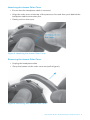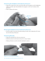
1
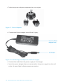
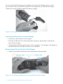
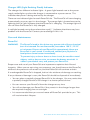
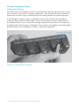
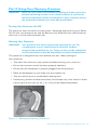
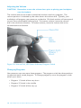
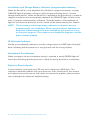
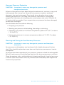
USER GUIDE HARMONY® By Advanced Bionics User Guide for the Auria® Harmony® Sound Processor Labeling The symbols below are used on the labeling for the product and for transportation, and their meanings are as follows: CAUTION: Federal law restricts this device to sale, distribution and use by or on the order of a physician. European Community Mark of Conformity Authorized to affix the CE Mark in 2006 REF Model Number SN Serial Number See Instructions for Use Store at temperatures between -20° C and +55° C Fragile Do not get wet Type of Protection: BF Dispose of Properly EN60601-1 Classification Information: Ordinary Construction Continuous Operation Internally Powered Equipment 2 User Guide for the Auria Harmony Sound Processor Date of Manufacture Table of Contents Part I: Assembling Your Auria Harmony Sound Processor . . . . . . . . . . . . . . .7 Overview . . . . . . . . . . . . . . . . . . . . . . . . . . . . . . . . . . . . . . . . . 7 Connecting Auria Accent Color Covers and Headpiece Caps . . . . . . . . . . 8 Attaching the Accent Color Headpiece Cap . . . . . . . . . . . . . . . . . 8 Removing the Accent Color Headpiece Cap . . . . . . . . . . . . . . . . . 8 Attaching the Accent Color Cover. . . . . . . . . . . . . . . . . . . . . . . . 9 Removing the Accent Color Cover . . . . . . . . . . . . . . . . . . . . . . . 9 Connecting the Headpiece to the Harmony® Processor . . . . . . . . . . . . 10 Removing the Headpiece from the Harmony Processor . . . . . . . . . . . . 10 Connecting Earhooks . . . . . . . . . . . . . . . . . . . . . . . . . . . . . . . . . 10 Removing Earhooks . . . . . . . . . . . . . . . . . . . . . . . . . . . . . . . . . 11 Part 2: Powering Your Harmony Processor . . . . . . . . The Auria PowerCel™ Battery Option . . . . . . . . Connecting the PowerCel™ Battery . . . . . . . Assembling the PowerCel Charger . . . . . . . Charging your PowerCels . . . . . . . . . . . . PowerCel™ Charger Car Adapter . . . . . . . . Inserting the PowerCels into the Charger . . . Removing the PowerCels from the Charger . . Charger LED (Light Emitting Diode) Indicator Care and Maintenance . . . . . . . . . . . . . . . . PowerCel . . . . . . . . . . . . . . . . . . . . . . Charger and Power Supply . . . . . . . . . . . . . . . . . . . . . . . . . . . . . . . . . . . . . . . . . . . . . . . . . . . . . . . . . . . . . . . . . . . . . . 12 . . . . . . . . . . . 12 . . . . . . . . . . . 12 . . . . . . . . . . . 13 . . . . . . . . . . . 14 . . . . . . . . . . . 15 . . . . . . . . . . . 15 . . . . . . . . . . . 16 . . . . . . . . . . . 16 . . . . . . . . . . . 17 . . . . . . . . . . . 17 . . . . . . . . . . . 18 Part 3: Using Your Harmony Processor . . . . . . . . . . . . . . Turning Your Processor On/Off . . . . . . . . . . . . . . . . Wearing Your Processor . . . . . . . . . . . . . . . . . . . . Adjusting the Volume . . . . . . . . . . . . . . . . . . . . . . Changing Programs . . . . . . . . . . . . . . . . . . . . . . Light Emitting Diode (LED) Status Indicator . . . . . . . . PowerCel Charge Status . . . . . . . . . . . . . . . . . Lock Status . . . . . . . . . . . . . . . . . . . . . . . . . Microphone/System Status (programmable feature) Low Battery and Change Battery Indicators . . . . . (programmable features) . . . . . . . . . . . . . . . ID Mismatch Indicator . . . . . . . . . . . . . . . . . . Microphone Test Indicator . . . . . . . . . . . . . . . . Processor Error Indicator . . . . . . . . . . . . . . . . . Harmony Processor Protection . . . . . . . . . . . . . . . . . . . . . . . . . . . 19 . . . . . . . . . . . 19 . . . . . . . . . . . 19 . . . . . . . . . . . 20 . . . . . . . . . . . 20 . . . . . . . . . . . 21 . . . . . . . . . . . 21 . . . . . . . . . . . 21 . . . . . . . . . . . 21 . . . . . . . . . . . . . . . . . . . . . . . . 22 . . . . . . . . . . . 22 . . . . . . . . . . . 22 . . . . . . . . . . . 22 . . . . . . . . . . . 23 User Guide for the Auria Harmony Sound Processor 3 Cleaning and Caring for Your Harmony Processor . . . . . . . . . . . . . . . 23 Warnings and Precautions . . . . . . . . . . . . . . . . . . . . . . . . . . . . . . 24 Electrostatic Discharge (ESD) . . . . . . . . . . . . . . . . . . . . . . . . . 24 Airport Security Metal Detectors . . . . . . . . . . . . . . . . . . . . . . . 25 X-ray Machines . . . . . . . . . . . . . . . . . . . . . . . . . . . . . . . . . 25 Part 4: Hearing with Your Harmony Processor. . . . . . . . . . . . . . . . . . . . . 26 Audio Mixing . . . . . . . . . . . . . . . . . . . . . . . . . . . . . . . . . . . . . 26 Earhooks . . . . . . . . . . . . . . . . . . . . . . . . . . . . . . . . . . . . . . . . 26 Auria Standard Earhook . . . . . . . . . . . . . . . . . . . . . . . . . . . . 26 Auria T-Mic Microphone . . . . . . . . . . . . . . . . . . . . . . . . . . . . 26 Auria Direct Connect Earhook . . . . . . . . . . . . . . . . . . . . . . . . . 27 Direct Connect Cable . . . . . . . . . . . . . . . . . . . . . . . . . . . . . . 27 To Connect the Direct Connect Cable . . . . . . . . . . . . . . . . . . . . 27 To Disconnect the Direct Connect Cable . . . . . . . . . . . . . . . . . . . 28 Audio Interface Cable . . . . . . . . . . . . . . . . . . . . . . . . . . . . . . 28 Adapters. . . . . . . . . . . . . . . . . . . . . . . . . . . . . . . . . . . . . . 29 Personal FM Systems . . . . . . . . . . . . . . . . . . . . . . . . . . . . . . 29 Connecting to a Personal FM System . . . . . . . . . . . . . . . . . . . . . 29 Infrared Systems . . . . . . . . . . . . . . . . . . . . . . . . . . . . . . . . . 30 Connecting to Infrared Systems . . . . . . . . . . . . . . . . . . . . . . . . 30 Troubleshooting Infrared Systems . . . . . . . . . . . . . . . . . . . . . . . 31 Hard-Wired Systems . . . . . . . . . . . . . . . . . . . . . . . . . . . . . . . 31 Interfacing with Hard-Wired Systems . . . . . . . . . . . . . . . . . . . . . 32 Troubleshooting Hard-Wired Systems. . . . . . . . . . . . . . . . . . . . . 33 Auxiliary Microphone . . . . . . . . . . . . . . . . . . . . . . . . . . . . . . 34 Auria iConnect™ Adapter. . . . . . . . . . . . . . . . . . . . . . . . . . . . 35 FM Receiver Compatibility . . . . . . . . . . . . . . . . . . . . . . . . . . . 35 iConnect Battery . . . . . . . . . . . . . . . . . . . . . . . . . . . . . . . . . 36 Replacing the Battery . . . . . . . . . . . . . . . . . . . . . . . . . . . . . . 36 Replacing the Battery Compartment . . . . . . . . . . . . . . . . . . . . . 37 iConnect Care and Maintenance . . . . . . . . . . . . . . . . . . . . . . . 38 Cleaning. . . . . . . . . . . . . . . . . . . . . . . . . . . . . . . . . . . . . . 38 Using the Phonak MicroLink MLxS With the iConnect . . . . . . . . . . 39 Telecoil . . . . . . . . . . . . . . . . . . . . . . . . . . . . . . . . . . . . . . . . . 40 Using the Built-in Telecoil . . . . . . . . . . . . . . . . . . . . . . . . . . . 40 External T-Coil (Auria T-Coil) . . . . . . . . . . . . . . . . . . . . . . . . . . 40 Using your Auria T-Coil . . . . . . . . . . . . . . . . . . . . . . . . . . . . . 41 Connecting to Telephones . . . . . . . . . . . . . . . . . . . . . . . . . . . . . . 42 Using the Telephone Receiver . . . . . . . . . . . . . . . . . . . . . . . . . 42 Using the Built-in Telecoil or Auria T-Coil . . . . . . . . . . . . . . . . . . 42 Using the T-Mic. . . . . . . . . . . . . . . . . . . . . . . . . . . . . . . . . . 42 4 User Guide for the Auria Harmony Sound Processor Using Direct Audio Input . . . . . . . . . . . . . . . . . . . . . . . . . . . . 42 Using a Speaker Phone . . . . . . . . . . . . . . . . . . . . . . . . . . . . . 43 Cell Phones . . . . . . . . . . . . . . . . . . . . . . . . . . . . . . . . . . . . 43 Phone Tips . . . . . . . . . . . . . . . . . . . . . . . . . . . . . . . . . . . . 43 Part 5: Other Accessories. . . . . . . . . . . . . . . . . . . . . . . . . . . . . . . . . 44 Auria Carrying Case . . . . . . . . . . . . . . . . . . . . . . . . . . . . . . . . . 44 Dri-Aid Function . . . . . . . . . . . . . . . . . . . . . . . . . . . . . . . . . 44 Regenerating the Dri-Aid Function . . . . . . . . . . . . . . . . . . . . . . 44 Cleaning the Carrying Case . . . . . . . . . . . . . . . . . . . . . . . . . . 45 Little Things Wallet . . . . . . . . . . . . . . . . . . . . . . . . . . . . . . . . . . 45 Accent Color Covers . . . . . . . . . . . . . . . . . . . . . . . . . . . . . . . . . 45 Part 6: Troubleshooting . . . . . . . . . . . . . . . . . . . . . . . . . . . . . . . . . . 46 Headpiece Retention . . . . . . . . . . . . . . . . . . . . . . . . . . . . . . . . . 46 Harmony Processor Retention . . . . . . . . . . . . . . . . . . . . . . . . . . . 46 What To Do If… . . . . . . . . . . . . . . . . . . . . . . . . . . . . . . . . . . . . 47 No Sound / Static / Muffled Sound / Distorted Sound . . . . . . . . . . . 47 Processor Gets Wet . . . . . . . . . . . . . . . . . . . . . . . . . . . . . . . 48 Green LED Light on Harmony Does Not Flash in . . . . . . . . . . . . . . . . Response to Loud Sounds (Programmable Feature) . . . . . . . . . . 48 Orange LED Light on Harmony Does Not Blink . . . . . . . . . . . . . . . . When the Processor is Turned On . . . . . . . . . . . . . . . . . . . . . 49 Decreases in PowerCel Life . . . . . . . . . . . . . . . . . . . . . . . . . . 49 PowerCel Will Not Charge . . . . . . . . . . . . . . . . . . . . . . . . . . . 49 Red Light on PowerCel Charger Illuminated . . . . . . . . . . . . . . . . 50 No Green Light on PowerCel Charger . . . . . . . . . . . . . . . . . . . . 50 No Orange Light on PowerCel Charger . . . . . . . . . . . . . . . . . . . 50 Contact Us . . . . . . . . . . . . . . . . . . . . . . . . . . . . . . . . . . . . . . . . . 51 User Guide for the Auria Harmony Sound Processor 5 Table of Figures Figure 1. Figure 2. Figure 3. Figure 4. Figure 5. Figure 6. Figure 7. Figure 8. Figure 9. Figure 10. Figure 11. Figure 12. Figure 13. Figure 14. Figure 15. Figure 16. Figure 17. Figure 18. Figure 19. Figure 20. Figure 21. Figure 22. Figure 23. Figure 24. Figure 25. Figure 26. Figure 27. Figure 28. Figure 29. Figure 30. Figure 31. Figure 32. Figure 33. Figure 34. Figure 35. Figure 36. Harmony Processor With Other External Components. . . . Removing the Accent Color Headpiece Cap. . . . . . . . . . Attaching the Accent Color Cover. . . . . . . . . . . . . . . . Removing Your Accent Color Cover. . . . . . . . . . . . . . . Connecting and Removing the Headpiece. . . . . . . . . . . Connecting an Earhook. . . . . . . . . . . . . . . . . . . . . . Removing an Earhook. . . . . . . . . . . . . . . . . . . . . . . O-ring. . . . . . . . . . . . . . . . . . . . . . . . . . . . . . . . . Connecting the PowerCel. . . . . . . . . . . . . . . . . . . . . Charger on a Flat Surface. . . . . . . . . . . . . . . . . . . . . Power Adapters. . . . . . . . . . . . . . . . . . . . . . . . . . . Connecting the Adapter to the Power Supply. . . . . . . . . . PowerCel Charger Car Adapter. . . . . . . . . . . . . . . . . . Using the PowerCel Charger Car Adapter. . . . . . . . . . . . Inserting and Removing a PowerCel From the Charger. . . . Cleaning the Charger. . . . . . . . . . . . . . . . . . . . . . . Wearing the Harmony Processor. . . . . . . . . . . . . . . . . Volume Dial, LED Status Indicator, Program Switch. . . . . . T-Mic. . . . . . . . . . . . . . . . . . . . . . . . . . . . . . . . . Direct Connect Cable. . . . . . . . . . . . . . . . . . . . . . . . Connecting/Disconnecting the Direct Connect Cable to the Direct Connect Earhook. . . . . . . . . . . . . . . . . . Audio Interface Cable (stereo). . . . . . . . . . . . . . . . . . Harmony Processor Interfacing With a Portable CD player. . Auxiliary Microphone. . . . . . . . . . . . . . . . . . . . . . . . iConnect Adapter. . . . . . . . . . . . . . . . . . . . . . . . . . Proper Pin Orientation. . . . . . . . . . . . . . . . . . . . . . . Opening the Battery Compartment. . . . . . . . . . . . . . . Removing Old Battery. . . . . . . . . . . . . . . . . . . . . . . Inserting the Battery. . . . . . . . . . . . . . . . . . . . . . . . Installing a New Battery Compartment. . . . . . . . . . . . . Attaching the MLxS to the iConnect. . . . . . . . . . . . . . . Turning On the MLxS. . . . . . . . . . . . . . . . . . . . . . . . Aligning the T-Coil on the Harmony Processor. . . . . . . . . T-Coil Snapped Correctly Into Place. . . . . . . . . . . . . . . Carrying Case Removable Insert. . . . . . . . . . . . . . . . . Little Things Wallet. . . . . . . . . . . . . . . . . . . . . . . . . 6 User Guide for the Auria Harmony Sound Processor . . . . . . . . . . . . . . . . . . . . . . . . . . . . . . . . . . . . . . . . . . . . . . . . . . . . . . . . . . . . . . . . . . . . . . . . . . . . . . . . . .7 . .8 . .9 . .9 .10 .10 .11 .11 .12 .13 .14 .14 .15 .16 .16 .18 .19 .20 .26 .27 . . . . . . . . . . . . . . . . . . . . . . . . . . . . . . . . . . . . . . . . . . . . . . . . . . . . . . . . . . . . . . . . .28 .28 .32 .34 .35 .35 .36 .36 .37 .37 .39 .39 .41 .41 .45 .45 Part I: Assembling Your Auria Harmony Processor Overview Your cochlear implant system consists of a microphone, Auria Harmony Processor, headpiece, cable and implant. Sounds in the environment are captured through the microphone located on your processor. The processor then converts this sound information into a distinctive digital code that is transmitted to your implant by the headpiece. The headpiece is held in place over your implant by a magnet that attracts to the implant’s magnet. Your implant converts the digital code into electrical signals that are delivered to your auditory (hearing) nerve. Your auditory nerve then carries this information to the brain, where it is interpreted as sound. Your processor provides you with access to the latest in sound processing technology. In addition, your processor allows you a wide range of wearing options that can be customized to fit your lifestyle needs. The processor is compatible with most Auria accessories including earhooks, PowerCel™ batteries, and headpieces, but excluding the Auria FireFly® diagnostic indicator, the System Sensor and the Auria AA PowerPak. Figure 1: Harmony Processor with Other External Components. User Guide for the Auria Harmony Sound Processor 7 Connecting Auria Accent Color Covers and Headpiece Caps WARNING: Small Parts Hazard: The processor, Accent Color Covers, Accent Color Headpiece Caps and the metal contact on the inside of the headpiece cap may cause choking if swallowed. Attaching the Accent Color Headpiece Cap • Align the color cap with your headpiece. • Gently place the color cap onto the headpiece (they are magnetically attracted). Removing the Accent Color Headpiece Cap • Hold the headpiece at the base with your thumb. • Slide your other thumb under the raised portion of the color cap. • Gently lift up removing the color cap. Figure 2: Removing the Accent Color Headpiece Cap. 8 User Guide for the Auria Harmony Sound Processor Attaching the Accent Color Cover • Ensure that the headpiece cable is removed. • Align the color cover at the top of the processor first and then push behind the headpiece cable connection port. • Gently push on the cover. Figure 3: Attaching the Accent Color Cover. Removing the Accent Color Cover • Unplug the headpiece cable. • Grasp the bottom of the color cover and pull off gently. Figure 4: Removing Your Accent Color Cover. User Guide for the Auria Harmony Sound Processor 9 Connecting the Headpiece to the Harmony Processor • Align the raised area on the end of the cable with the groove on the headpiece cable connection port located below the program switch on the body of the processor. • Slide in place until secure. Figure 5: Connecting and Removing the Headpiece. Removing the Headpiece from the Harmony Processor • Hold the cable’s connector (the plastic plug, not the wire) and gently pull it away from the Harmony Processor. Connecting Earhooks • Align the earhook flush with your processor. • Hold the earhook at the base and push to snap in place. • Gently pull back to confirm that the earhook is secure. Figure 6: Connecting an Earhook. 10 User Guide for the Auria Harmony Sound Processor Removing Earhooks • Remove the power source. • Turn the earhook slightly more than 1/4 turn in either direction until it comes off. Figure 7: Removing an Earhook. NOTE: If the orange o-ring is missing from the base of the post on your processor, contact AB Customer Service for a replacement. The earhooks may rotate excessively without the o-ring. Figure 8: O-ring. User Guide for the Auria Harmony Sound Processor 11 Part 2: Powering Your Harmony Processor WARNING: Power supplies and battery chargers should be operated in an open area to ensure adequate airflow. While no injury cases have resulted, components may become hot during normal use or a fault condition. If the device’s temperature results in discomfort or pain when touched, disconnect the power source and contact your local AB representative. The Auria PowerCel Battery Option The PowerCel is used to power your processor. If you select this option, the entire unit will sit behind your ear. Connecting the PowerCel Battery The tracks located along the PowerCel and processor direct the PowerCel into place making it easy to use. To connect a PowerCel: • Guide the PowerCel onto the tracks on the bottom of the processor. • Slide the PowerCel onto the processor until it stops. The PowerCel and processor should be aligned. • To remove, simply slide the PowerCel off while gently holding the processor and accent color cover (if applicable). Figure 9: Connecting the PowerCel. 12 User Guide for the Auria Harmony Sound Processor NOTE: Do not force the PowerCel onto the processor. The PowerCel is designed to be inserted in only one direction; applying force may damage your equipment. You may find it easier to remove the Accent Color Cover first before connecting/removing the PowerCel. If using the T-Mic, turn it gently in either direction prior to removing your PowerCel. This will prevent any damage to the T-Mic. Assembling the PowerCel Charger CAUTION: Only use the Charger provided for charging AB PowerCels. DO NOT use it to charge other batteries. Do not try to charge Auria PowerCels using a charger other than the one supplied by AB. WARNING: Power supplies and battery chargers should be operated in an open area to ensure adequate airflow. While no injury cases have resulted, during normal use or a fault condition, components may become hot. If the device’s temperature results in discomfort or pain when touched, disconnect the power source and contact AB. The charging system consists of the charger, power supply and power adapters. PowerCels are custom lithium ion rechargeable batteries. • Place the charger on a flat surface near an electrical outlet. Figure 10: Charger on a Flat Surface. User Guide for the Auria Harmony Sound Processor 13 • Select the power adapter appropriate for your region. Figure 11: Power Adapters. • Connect the Power Adapter to the Power Supply. Figure 12: Connecting the Adapter to the Power Supply. • Connect the cable from the power supply to the charger. • Insert the power adapter that you connected to the power supply into the wall outlet. A green light indicates proper connection. 14 User Guide for the Auria Harmony Sound Processor Charging your PowerCels The charger provided with your processor is designed to recharge up to four PowerCels simultaneously. It takes approximately 4–5 hours to fully recharge a depleted PowerCel. This will vary slightly for different PowerCel types. Your PowerCels do not need to be fully depleted before recharging. It is recommended that you use and recharge the PowerCel(s) at least once every 3 months. Please note that PowerCels will decrease in capacity with age, even if not in use. This is normal behavior for all rechargeable batteries and should not be considered a defect. Note for European customers: For proper disposal of rechargeable batteris in Europe, please return depleted batteries to the nearest AB location or the designated programming/follow-up center. In the United States and Canada, please call the Rechargeable Battery Recycling Coporation hotline at 800.822.8837 or visit their website at www.rbrc.com PowerCel Charger Car Adapter The PowerCel Charger Car Adapter allows you to charge your PowerCels in your automobile by using your car’s power outlet (cigarette lighter). Figure 13: PowerCel Charger Car Adapter. User Guide for the Auria Harmony Sound Processor 15 To use your PowerCel charger car adapter, first insert the adapter into your car’s power outlet. Next, connect the plug from the adapter to your PowerCel charger (where you would typically attach the power supply). Figure 14: Using the PowerCel Charger Car Adapter. Inserting the PowerCels into the Charger • Locate the slide tracks on the charger. • Position the PowerCel so that the battery contact is facing down toward the base of the charger. • Slide the PowerCel along the tracks until it engages. The charger is designed so the PowerCels can only be inserted in one direction. Removing the PowerCels from the Charger • Gently slide the PowerCel out of the slide tracks of the charger. Figure 15: Inserting and Removing a PowerCel From the Charger. 16 User Guide for the Auria Harmony Sound Processor Charger LED (Light Emitting Diode) Indicator The charger has different indicator lights. A green light located next to the power supply socket lights up when the charger is connected to a power source. This indicates that power is being received by the charger. There are two indicator lights for each PowerCel slot. The PowerCel will start charging automatically once you put it in the charger. The orange light is located next to the lightning bolt [] and indicates that the PowerCel is charging. The orange light will turn off when the PowerCel is fully charged. A red light located next to the exclamation mark [ ! ] indicates that there may be a problem with the PowerCel. Contact your audiologist if this is lit. Care and Maintenance PowerCel WARNING: The PowerCel used in this device may present risk of fire or chemical burn if mistreated. Do not disassemble, heat above 100°C / 212°F or incinerate. Dispose of used PowerCels appropriately. Never put PowerCels in your mouth. If swallowed, contact your physician or local poison control center immediately. To prevent injury or burns due to a short circuit, do not allow metal objects, such as keys or coins, to contact the battery terminals. A wallet is provided to carry and protect your PowerCels. Proper care and use of your PowerCels are important to optimize their life and longevity. When you are not using your processor, you should remove the PowerCel; otherwise the processor will remain on, and the PowerCel will continue to drain. If a rechargeable PowerCel is dropped, look at it for evidence of damage or cracking. If any evidence of damage is seen, the PowerCel should be disposed of immediately. • You can place a partially charged PowerCel in the charger. You may notice that a partially charged PowerCel will charge in a shorter period of time. • You can remove your PowerCel from the charger at any time. • You will not damage your PowerCels if they remain in the charger longer than the required charging time or overnight. • It is recommended that you use and rotate all PowerCels provided to you. This will maximize their lifespan. User Guide for the Auria Harmony Sound Processor 17 Charger and Power Supply Cleaning the Charger The PowerCels and charger contacts should be kept free from liquids, dirt and dust. Dirty contacts can result in charger malfunction. You should clean the contacts at least once a month using a hearing aid brush, being careful not to bend the pins. If the charger or power supply is dropped, inspect it for evidence of damage or cracking. If any evidence of damage is seen, the charger or power supply should be replaced. Prior to use, inspect the charger cable to ensure that it is not frayed or damaged and that the plug is not broken. If your power cord appears to be damaged, please contact your audiologist or AB as it should be replaced. Figure 16: Cleaning the Charger. 18 User Guide for the Auria Harmony Sound Processor Part 3: Using Your Harmony Processor WARNING: While no injury cases have resulted, components of the system may become hot during normal use or a fault condition. If a particular device’s temperature results in discomfort or pain, promptly remove the product and contact your local AB representative. Turning Your Processor On/Off The processor does not have an on/off switch. Attaching and removing your PowerCel will turn your processor on and off. Remove your PowerCel from your processor when not in use to optimize battery life. Wearing Your Processor WARNING: Your processor has been programmed especially for you. Do not attempt to use any sound processor that has not been programmed specifically for you. Doing so may provide suboptimal sound information and could potentially cause physical discomfort. The processor is designed to be worn behind your ear. When putting on your processor: • Turn down the volume on your processor before turning your system on. • Ensure that a power source has been properly attached. • Ensure that the headpiece is properly plugged into the processor. • Place the headpiece on your head over the implant site. • Turn the volume up to a comfortable listening level. • If necessary, perform a behavioral check, for example say a few words or check if the Ling 6 sounds (ah, oo, ee, s, sh, mm) can be detected/repeated. Figure 17: Wearing the Harmony Processor. User Guide for the Auria Harmony Sound Processor 19 Adjusting the Volume CAUTION: Remember to turn the volume down prior to placing your headpiece over the implant. The volume dial can be used to control the loudness level of a program. The volume position is indicated by the white dot on the volume dial. Typically, your audiologist will program your processor so that the 12 o’clock position will correspond to your most comfortable listening level. To increase volume, move the volume dial in the clockwise direction. To reduce volume, move the volume dial in the counterclockwise direction. Figure 18: Volume Dial, LED Status Indicator, Program Switch. Changing Programs Your processor can store up to three programs. The program switch has three positions to represent each stored program. To change programs, move the program switch either up or down. • Program 1: Switch all the way down • Program 2: Switch in the middle • Program 3: Switch all the way up 20 User Guide for the Auria Harmony Sound Processor Light Emitting Diode (LED) Status Indicator Your processor is equipped with a built-in Light Emitting Diode (LED) status indicator. The LED is a diagnostic light that provides users, parents, caregivers or teachers with information regarding the status of the processor. The LED is located above the volume dial and can be programmed to provide the information that follows. PowerCel Charge Status When your processor is first turned on, an ORANGE LED lighting sequence will indicate the PowerCel charge status as follows: • 4 quick blinks indicate that the PowerCel is fully charged. • 2–3 quick blinks indicate that the PowerCel is sufficiently charged to power the processor. • 1 quick blink indicates that the PowerCel charge is nearly depleted. • ORANGE LED doesn’t light up at all: The PowerCel is completely depleted. Lock Status The term lock refers to the successful communication between your processor and implant. Following the PowerCel charge status sequence, a RED light will begin to flash approximately once per second until lock is achieved. Depending on how the LEDs are programmed by your audiologist, the light will begin to flash immediately after the processor is unable to lock on your implant or it will begin to flash after a 5-second delay. Once your headpiece is properly positioned on your head, and information is transmitting to your implant, the flashing will stop. Microphone/System Status (programmable features) When the PowerCel status and lock sequence are complete, microphone and system status can be verified. A GREEN light will flicker in response to loud sounds presented near your microphone. This verifies that the microphone is receiving sound, data is being transmitted to the implant and your processor is receiving information back from the implant. The GREEN light is not expected to illuminate continuously during everyday use, especially if you are in a quiet environment. NOTE: The microphone/system status is a feature that is programmed by your audiologist. Please consult with your audiologist to determine if this feature has been enabled for your processor in any or all of your programs. This feature is disabled for programs with the built-in telecoil enabled. User Guide for the Auria Harmony Sound Processor 21 Low Battery and Change Battery Indicators (programmable features) When the PowerCel is near depletion but still able to support stimulation, a steady ORANGE light (low battery indicator) will illuminate indicating that it is time to change the PowerCel. When the PowerCel is depleted to the point that it is unable to support stimulation but not completely depleted, the ORANGE light will blink twice every 3 seconds (change battery indicator). Once the battery is fully depleted, no light will emit from the processor, and no sound will be transmitted to your Implant. NOTE: The low battery and change battery indicators are features that are programmed by your audiologist. Please consult with your audiologist to determine if these features have been enabled for your processor in any or all of your programs. These features are disabled for programs with the built-in telecoil enabled. ID Mismatch Indicator Should you accidentally attempt to use the wrong processor, a RED light will rapidly flash indicating that the processor is trying to lock with the wrong implant. Microphone Test Indicator When a program slot for microphone testing is selected, a steady GREEN light will illuminate indicating that the processor is ready for testing the built-in microphone. Processor Error Indicator In rare instances, your processor LED may emit a continuous RED light. This indicates a potential problem with your processor. If this should occur, first remove and replace your power source. If this does not resolve the problem, please contact your audiologist for additional troubleshooting. 22 User Guide for the Auria Harmony Sound Processor Harmony Processor Protection CAUTION: Immersion in water may damage the processor and headpiece electronics. All parts of the processor have been designed to tolerate rain, moisture, sweat, and dust expected from normal use. However, your processor contains advanced electronics that can be damaged. Care should always be taken when using or handling the processor. If you drop your processor, check that it is functioning properly. For information on checking your system, please refer to the “What to Do If” section of this user guide. If you suspect that your processor has been damaged, contact your audiologist. Care should be taken to avoid the following: • Dropping your processor. • Wearing your processor while bathing, showering or swimming. • Operating your processor in extreme temperatures (below 32° F/0° C or above 115° F/45° C). • Storing your processor in extreme temperatures (below -4° F/-20° C or above 131° F/55° C). Cleaning and Caring for Your Harmony Processor CAUTION: Immersion in water may damage the processor and headpiece electronics. Your processor and headpiece can be cleaned with a lightly dampened lint-free cloth. Care should be taken that water does not drip into any connector or into the microphone. To prevent intermittent operation of your processor, contacts on both the rechargeable PowerCel and processor should be kept free from dirt, dust, perspiration or moisture. Clean the contacts with a soft bristle brush (a hearing aid brush is best) at least once a month. Clean the contacts with a dry lint-free cloth immediately after exposure to moisture or perspiration. User Guide for the Auria Harmony Sound Processor 23 Warnings and Precautions As a cochlear implant user, there are a few precautions that you should take when in various environments. We recommend that you carry your Patient Identification Card with you at all times as a quick reference source. Should you have any questions or concerns, do not hesitate to contact your cochlear implant center or AB. Electrostatic Discharge (ESD) Your processor and its attachments are designed to withstand most static events without damage or interruption to your programs. However, there is a chance that high levels of static electricity will generate extreme electrostatic discharge events that may damage electronic components. Therefore, care should be taken to avoid exposing the headpiece, cables or sound processor to situations in which high levels of static electricity are created. Electrostatic Discharge (ESD) is present when you feel a spark jump from your body. ESD events are more likely to occur in very dry or cold environments. ESD events are less common in humid areas. High levels of electrostatic charge are known to build up under the following circumstances: • Walking on carpets • Sliding on plastic slides • Exiting an automobile • Pulling sweaters on and off • Touching TV or computer screens • Removing bedding materials You should take the following basic precautions in order to reduce the chances of an ESD event: • Electrostatic potential can be safely reduced by touching any person or object with your fingers prior to contact with a headpiece, cables or sound processor. Hand contact will safely equalize electric charge and prevent sparks from jumping to the processor system. When approached by someone (for example on carpet), touch him or her first with your hand prior to them touching your external cochlear implant components. Parents are advised to touch their child before they touch a headpiece or processor that their child is wearing. Also, before placing any part of a processor system on a table or other surface, you should first touch the surface. 24 User Guide for the Auria Harmony Sound Processor • Avoid contact between your processor/cable/headpiece and metal surfaces before you touch the metal surface with your hand. This is particularly important on the playground where high levels of static electricity can be easily generated, and extreme electrostatic discharge events can occur between a headpiece or processor and the metal that supports the playground equipment. A plastic tubular slide, for example, will quickly charge a child who then often immediately runs to a metal support structure such as a ladder. If at all possible, teach children who wear cochlear implant systems to touch with hands first. • Carefully exit motor vehicles, particularly in dry, cold weather. Try to avoid contact between processor system components and any vehicle metal as you exit. • When possible, remove your external equipment prior to removing sweaters. • The screens of televisions and computer monitors are highly charged. Contact is a problem for two reasons: First, the charge on screens can cause sparks. Second, brushing or touching a screen can transfer a charge that will then discharge when you come in contact with another object or person. Do not touch TV or computer screens. • Use fabric softener when washing clothes and bedding, this will reduce the likelihood of charge generation. If you strip a bed while wearing a processor system, please remember to use your hands to safely reduce any charge buildup you may have acquired. REMEMBER: Touch with hands first! Airport Security Metal Detectors Metal detectors and security scanners will not damage your implant. However, the implant system may activate the detector alarm as you pass through a security metal detector. Remember to carry your Patient Identification Card with you at all times. You might also hear a distorted sound caused by the magnetic field around the security scanner door or handheld screening wand. Turning down the volume on your processor before passing through security screening will ensure that those sounds, if they occur, are not too loud or uncomfortable. X-ray Machines X-ray machines will not damage the implant but may damage the internal processor microphone or the T-Mic. Avoid placing these items in cargo luggage or carry-on luggage that are screened with x-rays. During airport security screening, the processor/T-Mic should either be worn through the metal detector or be examined by hand. User Guide for the Auria Harmony Sound Processor 25 Part 4: Hearing with Your Harmony Processor Audio Mixing Audio mixing refers to the amplification ratio between your processor built-in microphone and any audio device connected to the processor post (this includes the T-Mic as well). Audio mixing allows your processor microphone to pick up nearby external sounds when connected to an audio device. This is important if you want to hear your voice or other sounds in the environment when connected to an audio device. Audio mixing is set by your audiologist during programming. A variety of audio options are available to meet your listening needs. Earhooks Auria Standard Earhook When using the Standard Earhook, the built-in microphone located at the top of the processor is the primary source for capturing sound. Auria T-Mic® Microphone The T-Mic Microphone is an integrated earhook and microphone combination. The microphone is omni-directional (accepts sound from all directions) and is designed to fit in the open bowl portion of your ear. The T-Mic is appropriate for everyday use and may provide improved benefit in difficult listening situations, such as in noisy environments or on the phone. NOTE: When fitting the T-Mic over your ear, bend by placing finger near the microphone and pushing gently. Avoid sharp angles (90°or greater) as they can shorten the lifespan of the T-Mic. Keep the T-Mic clean and dry. Dust, dirt, and excessive moisture could cause premature failure of the T-Mic. Figure 19: T-Mic. 26 User Guide for the Auria Harmony Sound Processor Auria Direct Connect Earhook The Direct Connect Earhook allows you to connect to a variety of audio devices. To connect, you will also need the Direct Connect Cable and an Audio Interface Cable. Your Direct Connect Earhook can also function as a standard earhook when programmed appropriately by your audiologist. Direct Connect Cable The Direct Connect Cable attaches to the Direct Connect Earhook and is typically used in conjunction with the Audio Interface Cable. The Direct Connect Cable is available in three different lengths. The auxiliary jack on the cable is 3.5 mm in size and is designed for stereo or mono input. Connect the adapter (included) to the Direct Connect Cable before connecting a device with a mono output, such as an AM radio, to the Direct Connect Cable. To Connect the Direct Connect Cable: • Remove the processor from your ear. • Hold the Direct Connect Earhook or base of the processor. • Gently push the Direct Connect Cable into the port at the top of the earhook. Figure 20: Direct Connect Cable An alternate method for attaching the Direct Connect Cable to the Direct Connect Earhook: • Rotate the connector 180 degrees. • Approach the Direct Connect at an angle. • Snap into place. • Rotate the connector 180 degrees to align. User Guide for the Auria Harmony Sound Processor 27 To Disconnect the Direct Connect Cable: • Remove the processor from your ear. • Hold the Direct Connect Earhook or base of the processor. • Hold the Direct Connect Cable at the connector. • Gently pull the Direct Connect Cable away from the port at the top of the earhook. Figure 21: Connecting/Disconnecting the Direct Connect Cable to the Direct Connect Earhook. Audio Interface Cable WARNING: This cable should only be used with battery-operated devices. Devices powered by direct AC current (i.e., devices that are plugged directly into a wall outlet) require an interface cable with appropriate safety protection. • The Audio Interface Cable provides an interface between the Direct Connect Cable and the audio device. This cable incorporates 3.5 mm stereo plugs that are designed to work with external audio devices. Figure 22: Audio Interface Cable (stereo). 28 User Guide for the Auria Harmony Sound Processor Adapters When connecting a patch cable to the Direct Connect system, an adapter may be needed, depending on the output of the device to which you are connecting. There are two main types of adapters: one for size and one for signal type. Size adapters will allow you to connect a patch cable that does not physically fit into the 3.5 mm audio jack. Signal adapters will convert the signal type to that used by the cochlear implant system. There are two main signal types: mono and stereo. Connecting the incorrect signal type can potentially degrade sound quality or even damage the external audio device. The audio jack on the Direct Connect is designed for stereo input. You can identify if a patch cable is intended for mono or stereo use by looking at the number of black rings located on the plug. Mono is designated by having one black ring whereas stereo has two black rings. Personal FM Systems An FM system is an assistive listening device to improve listening in noisy environments and overcome problems of listening at a distance. FM systems have a microphone/ transmitter worn by the speaker and a frequency-tuned receiver worn by the cochlear implant user. See the “Auria iConnect Adapter” section of this manual for more information. Body-worn receivers. Body-worn receivers can be used with the processor by using the Direct Connect Earhook, Direct Connect Cable and a custom patch cable. The custom patch cable is typically available for purchase through the FM manufacturer. If the FM manufacturer does not supply the patch cable, please contact your audiologist or AB for further assistance. Cube-style receivers. Some cube-style receivers require the use of both the Direct Connect Earhook and Direct Connect Cable for use with the processor. A patch cable is typically not necessary as the cube-style receiver should interface directly with the auxiliary jack on the Direct Connect Cable. Headphone wearing option. If an FM receiver offers headphones, the T-Mic might be an appropriate wearing option for you. Simply place the headphones from the FM receiver over your T-Mic; no patch cable is necessary. Connecting to a Personal FM System: • Select the appropriate patch cable or adapter for your processor (as applicable). • Ensure that you are using a charged battery and PowerCel for both the FM system and the processor. • With the FM system and processor turned off, attach the patch cable. User Guide for the Auria Harmony Sound Processor 29 • Set the volume/gain control on the FM receiver to the minimum setting (some FM systems may not have this control). • Turn down the volume dial on the processor. • Set the processor to the appropriate program. • In sequence, turn on the FM transmitter, receiver and processor-in that order (this will ensure that no adverse sound percepts are heard). • Gradually increase the volume on the processor to user setting (typically 12:00). • Increase the FM gain/volume control to a comfortable listening level or as specified per the FM manufacturer. Infrared Systems Infrared systems are another type of assistive listening device designed to improve hearing in difficult listening environments. Infrared systems have a transmitter/emitter that sends sound information to a receiver that is worn by the cochlear implant user. Some infrared receivers have an audio output socket that will allow you to interface directly with your processor. In addition to the Direct Connect Earhook and Direct Connect Cable, these receivers will require a specially designed patch cable that can be obtained from a variety of sources, including the infrared manufacturer. If you encounter any difficulties obtaining a patch cable, please contact your audiologist or AB for assistance. Consult with your audiologist in determining if an infrared system is appropriate for you. When using an infrared system, your audiologist may need to modify one of your programs for its use. Connecting to Infrared Systems: • Ensure that the appropriate patch cable has been obtained for your processor. • With the infrared system and processor turned off, attach the patch cable. • Set the volume/gain control on the infrared receiver to the minimum setting (some infrared systems may not have this control). • Turn down the volume dial on the processor. • Set the processor to the appropriate program. • In sequence, turn on the infrared transmitter, receiver and processor—in that order (this will ensure that no adverse sound percepts are heard). • Gradually increase the volume on the processor to user setting (typically 12:00). • Increase the infrared gain/volume control to a comfortable listening level or as specified per the infrared manufacturer. 30 User Guide for the Auria Harmony Sound Processor Troubleshooting Infrared Systems • Are you using a good PowerCel? • Are you using the correct program on your processor? • Ensure that the patch cable does not entangle with the headpiece cable (as applicable). • Ensure that the appropriate patch cable for the make and model of infrared system is being used. • Proper care of the patch cable (e.g., avoid sharply bending the cable) will maximize its life. • Certain environmental conditions, such as the presence of large objects or bright, direct light, may cause interference. Consider moving to another location in the room. Hard-Wired Systems CAUTION: Only battery-powered devices should be connected to the Direct Connect unless a patch cable with special electronic components is used. Ignoring this caution could lead to damage to your processor and/or the audio device. Further, unpleasant sensations or sounds may be perceived by the cochlear implant user. A hard-wired system can be described as any system that provides a direct physical connection between the audio device (sound source) and the cochlear implant user’s processor. Examples of this can include interfacing with your MP3/CD player, auxiliary/lapel microphone, etc. Hard-wired systems are an appealing option and are many times fairly inexpensive to implement. However there are a few precautions to consider: • Hard-wired systems require the use of a patch cable. The Audio Interface Cable provided with your Direct Connect system is appropriate when connecting to battery-operated devices. • Choose interface cables that are not too long. Long cables may pose a safety problem in which you can trip over the excess cable. In addition, long cables increase the distance between the audio device and processor and can also act as an antenna. Thus, they may pick up unwanted signals and degrade the incoming quality of the signal. User Guide for the Auria Harmony Sound Processor 31 Interfacing with Hard-Wired Systems: • Select the appropriate patch cable. As a reminder, the Direct Connect Cable uses a standard 3.5 mm audio jack that is designed to accept stereo input. If you have additional questions regarding patch cables, please contact your audiologist or AB for additional assistance. • With the audio device and processor turned off, attach the patch cable. • Turn down the volume on the audio device to the minimum setting. • Turn down the volume dial on the processor. • Set the processor to the appropriate program. • Turn on the audio device, then the processor—in that order (this will ensure that no adverse sound percepts are heard). • Gradually increase the volume on the processor to user setting (typically 12:00). • Increase the volume control on the audio device to a comfortable listening level. Figure 23: Harmony Processor Interfacing With a Portable CD player. 32 User Guide for the Auria Harmony Sound Processor Troubleshooting Hard-wired Systems: • Are you using a good PowerCel? • Are you using the appropriate patch cable? • Are you using the appropriate program on your processor? • Is the audio device turned on? • Is the patch cable inserted properly into the audio device, and is the volume turned up? • Long cables can get tangled around objects. Take care when draping long patch cables across busy areas at home and at work. • Is there any cable damage? • Proper care of the patch cable (i.e., avoid sharp bending of the cable) will maximize its life. Headphone Connectivity Option The T-Mic can provide a cable-free connectivity option when interfacing with a variety of audio devices. If an audio device uses mono headphones or stereo headphones with a mono adapter, the T-Mic is an appropriate listening option. To use, simply place the headphones into the audio jack of the audio device and place the headphones over your T-Mic. User Guide for the Auria Harmony Sound Processor 33 Auxiliary Microphone The Auxiliary Microphone does not come with your kit. It can be purchased by contacting AB. The Auxiliary Microphone, also called a lapel microphone, is an additional microphone that can be used in a variety of ways. The Auxiliary Microphone can be handheld, passed from speaker to speaker in difficult listening environments or worn on your lapel/shirt collar. The Auxiliary Microphone plugs into the auxiliary jack located on the end of the Direct Connect Cable. Before using your Auxiliary Microphone, it is important that you consult with your audiologist who will modify or determine which program in your processor can provide optimal benefit for your listening needs. Figure 24: Auxiliary Microphone. 34 User Guide for the Auria Harmony Sound Processor Auria iConnect™ Adapter WARNING: The Auria Accent Color Covers, the Headpiece Color Caps, the metal contact on the inside of the color cap, earhooks, battery, and the battery compartment of the iConnect may cause choking if swallowed. The Auria iConnect Adapter does not come with the Harmony Kit. It can be purchased by contacting AB. Figure 25: iConnect Adapter. FM Receiver Compatibility The Phonak MicroLink MLxS is an FM receiver compatible with the iConnect. For easier access to the controls, the MLxS needs to have a pin orientation as illustrated. Consult the MLxS user reference materials for instructions on how to orient the pins. Figure 26: Proper Pin Orientation. User Guide for the Auria Harmony Sound Processor 35 iConnect Battery WARNING: Batteries are toxic when swallowed. Keep them out of reach of young children. If batteries are swallowed, please seek immediate medical attention. The iConnect can only use a standard size 10 hearing aid battery. Do not use any other battery. Replacing the Battery To replace the battery, open the battery compartment and remove the old battery by tilting the iConnect. Figure 27: Opening the Battery Compartment. Figure 28: Removing Old Battery. 36 User Guide for the Auria Harmony Sound Processor Do not attempt to open the battery compartment further than shown. Remove the protective foil from the new battery. Hold the battery as shown and insert the battery bevel end (negative) first. Gently shut the battery compartment until it clicks in place. Do not use excessive force when handling the battery compartment. Figure 29: Inserting the Battery. If there is excessive resistance when closing the compartment, make sure that the battery is correctly inserted. The compartment will not close completely if the battery is improperly inserted. Dispose of old batteries appropriately. Replacing the Battery Compartment When the battery compartment is subject to high force, it may fracture. A new battery compartment snaps on easily. Figure 30: Installing a New Battery Compartment. User Guide for the Auria Harmony Sound Processor 37 iConnect Care and Maintenance When the iConnect is not in use, remove the battery from the compartment and store it in a safe place. The Auria Carrying Case insert functions as a Dri-Aid Kit. Regularly put the iConnect in the Auria Carrying Case to help prevent moisture build-up. Avoid the following: • Operating the iConnect in extreme temperatures (below 32° F/0° C or above 115° F/45° C). • Storing iConnect in extreme temperatures (below -4° F/-20° C or above 131° F/55° C). • Dropping the iConnect on a hard surface. • Opening the battery compartment further than shown. NOTE: After the protective foil has been removed, zinc air batteries begin to drain even when not in use in a device. To confirm battery life, use a hearing aid battery tester. Consult your hearing professional. Cleaning If necessary, the exterior of the iConnect can be cleaned with a slightly dampened cloth or tissue. Do not use soap or solvent. 38 User Guide for the Auria Harmony Sound Processor Using the Phonak MicroLink MLxS With the iConnect To use the MLxS receiver with the iConnect, follow these steps: • Turn off the MLxS receiver. • Attach the MLxS receiver to the iConnect by lining up the thicker pin with the wider socket hole. Forcing the pins into the holes will result in damage to the unit. Figure 31: Attaching the MLxS to the iConnect. • Attach the iConnect by aligning it to the processor post and gently pushing straight in until it lightly clicks in place. • Operate the MLxS by turning on the FM transmitter, then the MLxS, and finally the Harmony. Use the 1-dot setting for the MLxS. Figure 32: Turning On the MLxS. • To use the iConnect, the processor must contain a program set up for auxiliary input. A 50/50 or 30/70 Mic/Aux mix is recommended for use in the classroom. Switch to this program when using the processor with the iConnect. Please contact your audiologist for fitting advice if necessary. • To remove the iConnect, first turn off the MLxS. Then turn the earhook slightly more than 1/4 turn in either direction until it pops off. User Guide for the Auria Harmony Sound Processor 39 Telecoil Using the Built-in Telecoil Telecoils provide wireless access to hearing-aid–compatible telephones and inductive loop systems (found in some public facilities). Telecoils capture electromagnetic fields in the environment and deliver these signals to your processor. A telecoil is built into your processor and is programmed by your audiologist. To activate your telecoil, first consult with your audiologist to determine if a program in your processor has been created for its use. If so, your telecoil will activate once you switch to the designated program. For your telecoil to be effective, you must have access to a looped system or a hearingaid–compatible telephone. This will allow the telecoil to receive the electromagnetic field generated by these devices. If you are attempting to use your telecoil with a noncompatible audio device, you may hear no sound or a low-level humming or buzzing noise. NOTE: Telecoils are known to be susceptible to magnetic noise generated by most industrial lighting fixtures, store and airport security scanners, band scanners, power transformers, motor starters, and monitor screens. External T-Coil (Auria T-Coil) WARNING: Small parts hazard: Parents and caregivers should be counseled that the external implant system contains small parts. The Auria T-Coil may cause choking if swallowed. The Auria T-Coil does not come with your kit. Contact AB if you would like to purchase one. In addition to an internal telecoil built into your processor, an external Auria T-Coil is also available should this better meet your lifestyle and needs. The external T-Coil provides the same access to private and public loop systems and hearing-aid– compatible telephones as your internal telecoil. The external T-Coil connects to your Direct Connect Earhook and can be rotated to optimize the electromagnetic field reception. To use your T-Coil, first consult with your audiologist to determine if a program in your processor has been created for its use. If so, your T-Coil will activate once you switch to the designated program. 40 User Guide for the Auria Harmony Sound Processor Using your Auria T-Coil: To attach the T-Coil to your Direct Connect Earhook: • Align the Auria T-Coil as shown. Figure 33: Aligning the T-Coil on the Harmony Processor. • Gently push the T-Coil onto the Direct Connect Earhook until it lightly snaps in place. Figure 34: T-Coil Snapped Correctly Into Place. For your T-Coil to be effective, you must have access to a looped system or a hearingaid–compatible telephone. This will allow your T-Coil to receive the electromagnetic field generated by these devices. If you are attempting to use your T-Coil with a noncompatible audio device, you may hear no sound or a low-level humming or buzzing noise. To optimize reception with your T-Coil, rotate the T-Coil 90 degrees to the left or to the right. User Guide for the Auria Harmony Sound Processor 41 Connecting to Telephones There are a variety of ways for you to use your telephone. Using the Telephone Receiver • Place the telephone receiver directly over your processor microphone. Using the Built-in Telecoil or Auria T-Coil • The built-in telecoil or Auria T-Coil will allow you to pick-up the electromagnetic field from the telephone. To use the telecoil/T-Coil most effectively, you must ensure that you are using a telecoil/T-Coil compatible telephone. Consult with your audiologist to determine which program will provide you with the most benefit. Remember that your telecoil/T-Coil needs to be programmed by your audiologist. • When using the telecoil/T-Coil, you may need to orient the telephone receiver over the processor in various areas to determine which location provides you with the optimal signal reception. Using the T-Mic The T-Mic is an earhook option that places a microphone at the opening of your ear. To use the telephone with your T-Mic, simply hold the receiver of the telephone directly over the opening of your ear. Using Direct Audio Input If your telephone contains an audio jack, you may be able to directly interface your processor with the telephone. Doing so will require the use of your Direct Connect Earhook, Direct Connect Cable and an interface cable. You will need to consult with your audiologist to determine which program is most appropriate for you when directly interfacing with the telephone. Should you need assistance selecting an appropriate patch cable, please contact your audiologist or AB for assistance. Alternatively, if your telephone contains an audio jack that can be used with headphones, your T-Mic may be a more suitable option for you. To connect, insert the headphones into the audio jack on the telephone and place the headphones directly over your T-Mic. 42 User Guide for the Auria Harmony Sound Processor Using a Speaker Phone Speakerphones are another option when you want to use the telephone. By using a speakerphone, no patch cables or program changing is necessary; simply turn on the speakerphone and listen as you would during normal use with your processor. Cell Phones CAUTION: Using or being in the vicinity to someone who is using certain digital cellular phones may cause interference with the cell phone’s reception or problems with the quality of sound from your implant system. If such interference occurs, move away from the cell phone. Before purchasing a digital cellular phone, you should evaluate whether or not interference is present. Phone Tips • Remember that telephone use takes time and practice. Be patient. Telephone use will often improve over time. • Practice listening with familiar speakers, such as your family members, friends, therapist or audiologist. • It may be helpful to become familiar with the topic of discussion ahead of time. For example, tell your friend to call you at a specific time to talk about a specific topic (e.g., Call me at 6:00 pm to talk about going to the movies). • You may need to practice with several telephones to find one that is right for you. • When selecting a cellular phone, remember to try the phone first. User Guide for the Auria Harmony Sound Processor 43 Part 5: Other Accessories Auria Carrying Case The Auria Carrying Case is included in your processor kit. It is a multifunctional case that can carry all your basic processor components. It can hold your processor with any PowerCel configuration or earhook. Dri-Aid Function Your Auria Carrying Case allows you to carry your processor with you and remove excess moisture as you store it at night. The carrying case contains a removable insert that serves as a Dri-Aid kit. It is recommended that you use your Dri-Aid kit on a regular basis. For those living in humid areas, daily use of the Dri-Aid kit is encouraged to prevent moisture build-up in the electronics. The removable insert contains silica crystals that can be regenerated. On the bottom of the insert is a semi-transparent window that lets you see the silica crystals as they absorb moisture. The crystals are yellow when dry, but they will turn green (dark) as moisture is absorbed. When the crystals appear green (dark), you should regenerate the insert. Regenerating the Dri-Aid Function CAUTION: Do not put the outer portion of the Auria Carrying Case, your processor, PowerCels, or any accessories in the oven. Only the insert is designed to be heated. Do not heat over 260°F/126°C or the silica crystals may become damaged. • Remove the insert from the carrying case. • Place the insert on a cookie sheet. • Bake insert at 200°F/93°C for approximately 11/2 to 2 hours or until crystals have turned gold. • If crystals are still green (dark) after heating, try baking them longer, up to a total of six hours. If they stay green, the Dri-Aid insert needs to be replaced. 44 User Guide for the Auria Harmony Sound Processor Figure 35: Carrying Case Removable Insert. Cleaning the Auria Carrying Case CAUTION: Do not immerse your Auria Carrying Case in water as it may damage or destroy the silica crystals. If necessary, your Auria Carrying Case can be cleaned with a slightly dampened cloth or tissue. Do not use soap or solvents. Little Things Wallet The Little Things Wallet is also provided with your processor kit. This wallet allows you to carry either two spare PowerCels and extra earhooks or a third PowerCel safely and conveniently in your pocket or purse. Figure 36: Little Things Wallet. Accent Color Covers Your processor is designed to allow for changes in Accent Color Covers to meet your individual preference and lifestyle. Accent Color Covers are available in many color options for use with both the PowerCel Slim and the PowerCel Plus battery options. User Guide for the Auria Harmony Sound Processor 45 Part 6: Troubleshooting WARNING: While no injury cases have resulted during normal use or a fault condition, components of the system may become hot. If a particular device’s temperature results in discomfortor pain, promptly remove the product and contact AB. Headpiece Retention CAUTION: Adding too many magnets to your headpiece may cause physical discomfort and can potentially damage the skin around your implant site. Do not attempt to add additional magnets to your headpiece unless advised by your audiologist or AB. Shortly following your surgery, you may notice slight swelling near your implant site. This is part of the normal healing process and may take some time to resolve. If the swelling does not fully resolve by your initial stimulation, you and your audiologist may need to take additional actions to ensure that your headpiece adheres and successfully communicates with your implant. Again, any residual swelling should resolve over time. However, several options to retain your headpiece include: • Having your audiologist increase magnet strength in your headpiece. • Temporarily shaving your hair around the implant site. • Applying pressure to the headpiece with a headband, baseball cap, etc. Harmony Processor Retention The processor was designed to fit securely and comfortably behind most users’ ears. However, you may find that additional retention of your processor is desired during everyday use or in specific environments (e.g., when engaging in physical activities). • An earmold is the most commonly used solution for providing additional retention. Earmolds are available in a variety of styles, materials and colors. Please consult with your audiologist in determining if an earmold is appropriate for you. A specially designed earmold for use with the T-Mic is available. 46 User Guide for the Auria Harmony Sound Processor What To Do If… The following is a description of how to troubleshoot your processor given a specific symptom. If the problem persists after trying the suggestions below, contact your audiologist or AB for assistance. No Sound / Static / Muffled Sound / Distorted Sound • Check your connections, including PowerCel, earhook and cables. • Check your volume dial. • Is your headpiece positioned over your implant site? • Is your PowerCel charged and inserted properly? Try another PowerCel. • Are you using the appropriate program? Try another program. • Check the microphone/system status using your LED. • Replace the cable/headpiece. • Clean the contact on both your PowerCel and processor. • Remove any materials (hat, headband, scarf, etc.) that may be covering your microphone. • Perform a test of the built-in microphone using an empty program slot. Contact your audiologist for instructions. • Try another audio input source such as an Auxiliary Microphone or your Direct Connect Earhook interfaced with an audio device (i.e., CD/MP3 player). - You will need to use a program that is designated to accept an external audio source. - If this resolves the problem, place your processor and T-Mic (if applicable) in the Auria Carrying Case/Dri-Aid overnight. If no sound is present the next day, contact your audiologist. • Check for visible damage to components. • Contact your audiologist for further troubleshooting if necessary. User Guide for the Auria Harmony Sound Processor 47 Processor Gets Wet WARNING: Your processor or headpiece should be serviced only at AB. Do not attempt to open or repair the processor. Do not continue to use the processor if any part of it is damaged. Unauthorized opening of the processor, or other equipment, will void the warranty and may compromise system performance. All parts of the processor have been designed to tolerate rain, moisture, sweat, and dust expected from normal use. However, if the processor gets wet, perform the following steps as soon as possible: • Remove your PowerCel. • Gently shake your processor to drain any excess water. • Place your processor in your Auria Carrying Case/Dri-Aid. IMPORTANT: Place your processor in your carrying case for 24 hours. DO NOT try to speed up the drying process by using a microwave oven, convection oven or hair dryer. This could further damage the internal electronics. • If after performing the above steps, you notice a deterioration in sound quality or volume, contact your audiologist for further troubleshooting. Green LED Light on Processor Does Not Flash in Response to Loud Sounds (programmable features) • Confirm that this feature is enabled. • Recheck the PowerCel status. • Perform a System Operation Check. • Try another program on your processor. • Try another audio input source such as an Auxiliary Microphone or your Direct Connect Earhook interfaced with an audio device (e.g., CD/MP3 player). - You will need to use a program that is designated to accept an external audio source. - If this resolves the problem, place your processor and T-Mic (if applicable) in the Auria Carrying Case/Dri-Aid overnight. If no sound is present the next day, contact your audiologist. • Replace the cable/headpiece. • Refer to “No Sound / Static / Muffled Sound / Distorted Sound” section for additional troubleshooting steps. • Contact your audiologist for further troubleshooting if necessary. 48 User Guide for the Auria Harmony Sound Processor Orange LED Light on Harmony Does Not Blink When the Processor is Turned On • Check your connections between the PowerCel and processor. • Replace your PowerCel with one that is fully charged. • Clean PowerCel and processor contacts. • Contact your audiologist for further troubleshooting if necessary. Decrease in PowerCel Life A variety of factors can impact PowerCel life, including: • Changes to your program made by your audiologist. • The type of program and processor that you are using. • The various listening environments that you encounter. • Care and maintenance of your PowerCels. • Age of PowerCels. • Exposure to high temperature or impact. If you notice a sudden decrease in PowerCel life: • Clean the PowerCel, charger, and processor contacts. • Ensure that your charger is receiving power. • Check the lighting sequence on your charger to ensure proper operation. • Ask yourself the following: - Have I recently been reprogrammed? - Am I using old PowerCels? • If you answered yes to either of these questions, please consult with your audiologist for additional troubleshooting. PowerCel Will Not Charge If the orange light does not light up when a PowerCel is placed in the charger, this likely indicates that the PowerCel is already charged. If the PowerCel is unable to power the processor: • Try charging the PowerCel in another charging slot. • Unplug and replug all connections. • Try another PowerCel with your processor. • Clean the PowerCel and charger contacts. User Guide for the Auria Harmony Sound Processor 49 Red Light on PowerCel Charger Illuminated • Try charging the PowerCel in another charger bay. • If a red light appears again after 90 minutes of charging, contact your audiologist. The PowerCel may be faulty. NOTE: If the red light is still illuminating after the PowerCel is removed, reset the charger’s power by unplugging and replugging your charger into the wall outlet. This will reset your charger and turn the red light off. Alternatively, the red light will also turn off when another PowerCel is placed in the charger bay. No Green Light on PowerCel Charger • Check your connections. - Is your charger plugged firmly into the wall outlet? - Are your adapter and power supply firmly connected? • Try your car charger adapter. • Try plugging your charger into another wall outlet. • Contact your audiologist or AB for further troubleshooting. No Orange Light on PowerCel Charger • If the orange light does not illuminate upon placing a PowerCel onto the charger, this likely indicates that the PowerCel is already charged. • If there is no orange light and your PowerCel is not working properly, please contact your center or AB for further assistance. 50 User Guide for the Auria Harmony Sound Processor Contact Us Advanced Bionics is committed to providing the highest quality products and service to our customers. We welcome your comments regarding the Harmony Processor or your suggestions to improve our products. Please feel free to contact AB or discuss your suggestions with your implant professional. HEADQUARTERS Advanced Bionics, LLC 12740 San Fernando Road Sylmar, CA 91342, USA 877.829.0026 in US and Canada 800.678.3575 TTY 661.362.1400 661.362.1500 Fax [email protected] EUROPE Advanced Bionics SARL 76 rue de Battenheim 68170 Rixheim, France +33.0.3.89.65.98.00 +33.0.3.89.65.50.05 Fax [email protected] ASIA-PACIFIC Advanced Bionics Asia-Pacific Limited Suite 4203, 42/F, Tower One Lippo Centre, 89 Queensway Hong Kong 852.2526.7668 852.2526.7628 Fax [email protected] LATIN AMERICA Advanced Bionics Mann Biomedical Park 25129 Rye Canyon Loop Valencia, CA 91355, USA 661.362.1840 661.362.4604 Fax [email protected] User Guide for the Auria Harmony Sound Processor 51 Advanced Bionics®, Auria®, T-Mic®, FireFly®, PowerCel™, Harmony® and iConnect™ are trademarks of Advanced Bionics, LLC in the United States of America and other countries. This device is protected under one or more of the following U.S. Patents: 4,400,590, 4,405,831, 4,495,917, 4,686,765, 4,721,551, 4,819,647, 4,837,049, 4,931,795, 4,969,468, 4,990,845, 4,991,582, 5,443,493, 5,477,855, 5,513,793, 5,522,865, 5,531,774, 5,545,191, 5,569,307, 5,571,148, 5,584,869, 5,601,617, 5,603,726, 5,609,616, 5,626,629, 5,738,270, 5,776,172, 5,833,714, 5,876,425. Other U.S. and/or foreign patents are pending. 9050050013 Rev A FEB09_ 3-01002-B-5 52 User Guide for the Auria Harmony Sound Processor www.AdvancedBionics.com HEADQUARTERS Advanced Bionics, LLC 12740 San Fernando Road Sylmar, CA 91342 USA 877.829.0026 in US and Canada 800.678.3575 TTY 661.362.1400 661.362.1500 Fax [email protected] ASIA-PACIFIC Advanced Bionics Asia-Pacific Limited Suite 4203, 42/F, Tower One Lippo Centre, 89 Queensway Hong Kong 852.2526.7668 852.2526.7628 Fax [email protected] EUROPE Advanced Bionics SARL 76 rue de Battenheim 68170 Rixheim, France +33.0.3.89.65.98.00 +33.0.3.89.65.50.05 Fax [email protected] LATIN AMERICA Advanced Bionics Mann Biomedical Park 25129 Rye Canyon Loop Valencia, CA 91355, USA 661.362.1840 661.362.4604 Fax [email protected] 9050050013 Rev A FEB09_ 3-01002-B-5 ©2009 Advanced Bionics or its affiliates.