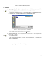
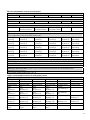
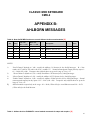
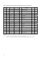
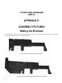
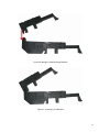
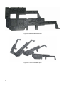
1
Dmbttjd!Pshbo!Xpslt!
CMK-2
Classic MIDI Keyboard
User Manual
Version 1.00.00
Div. of:
ARTISAN CLASSIC ORGAN INC.
1
CLASSIC MIDI KEYBOARD
CMK-2
TABLE OF CONTENTS
LIMITED WARRANTY ............................................................................................... 7
INTRODUCTION ........................................................................................................ 9
Description......................................................................................................................................9
Package Contents.........................................................................................................................10
Table 1: Package Contents ..................................................................................................................................... 10
Figure 1: CMK-2 components (from L-R, Top to Bottom): ...................................................................................... 10
Figure 2: CMK-2 connections .................................................................................................................................. 11
INSTALLATION ....................................................................................................... 12
Physical Installation .....................................................................................................................12
Figure 3a: Bracket Installation ................................................................................................................................. 12
Figure 3b: Bracket Goes Over Top of the Keyboard Mount .................................................................................... 13
Figure 3c: Install 3 #8 Screws in the Underside ...................................................................................................... 13
Connections (Rear View) .............................................................................................................13
Figure 4: Rear View Connections ............................................................................................................................ 13
Power Connections ......................................................................................................................14
Figure 5: Power Terminal Block Connections ......................................................................................................... 14
MIDI Connections .........................................................................................................................15
Figure 6: Connecting MIDI Cables to a Keyboard Stack......................................................................................... 15
Connecting Swell Shoes ..............................................................................................................15
Figure 7 Wiring Schematic for Analog input ............................................................................................................ 16
Table 2: Connection Chart....................................................................................................................................... 16
Software Installation (Windows users only)............................................................................................................. 17
MIDI SPECIFICATION ............................................................................................. 18
Ahlborn..................................................................................................................................................................... 18
2
Table 3: Classic Module .......................................................................................................................................... 18
Table 4: Romantic Module........................................................................................................................................ 18
Table 5: 201 Module ................................................................................................................................................. 19
Table 6: 202 Module ................................................................................................................................................. 19
HAUPTWERKTM ........................................................................................................................................................ 20
Table 7a: MIDI messages relevant to Hauptwerk .................................................................................................... 20
Table 7b: Configuration for 2 and 3 manual stack with Hauptwerk St. Anne Mosley............................................... 20
SCPOPTM .................................................................................................................................................................. 21
MIDI Hardware Specification .......................................................................................................21
Figure 8 Schematic of 5-pin DIN connector............................................................................................................. 22
CMK-2 HARDWARE CONFIGURATION................................................................. 23
Introduction...................................................................................................................................23
Power-On Self Test.......................................................................................................................23
Analog Input Pins .........................................................................................................................23
MIDI Crescendo – only for Ahlborn Archive modules.............................................................................................. 23
MIDI Volume ............................................................................................................................................................ 23
MIDI Expression....................................................................................................................................................... 23
Programming ................................................................................................................................24
Table 8: Piston programming functions .................................................................................................................... 24
CMK-2 SOFTWARE CONFIGURATION ................................................................. 26
Introduction...................................................................................................................................26
Software Installation.....................................................................................................................26
Figure 9 Upon clicking on the ‘CMK-2_Setup.exe’ file, the above window will appear. .......................................... 27
Figure 10 Allows the user to select a directory to install the CMK-2 program file ................................................... 27
Figure 11 Setup adds an icon to the start menu for convenient access.................................................................. 28
Figure 12 Setup provides the option of creating an icon on the Windows desktop................................................. 28
Figure 13 Confirmation window ............................................................................................................................... 29
Figure 14 Setup progress window ........................................................................................................................... 29
Figure 15 Confirms installation was successful....................................................................................................... 30
Software Startup ...........................................................................................................................31
Figure 16 CMK-2Config software startup screen. ................................................................................................... 31
Figure 17 CMK-2Config software main menu. ........................................................................................................ 31
Configure a CMK-2 from scratch.................................................................................................32
Figure 18 CMK-2Config software attempting to connect with the CMK-2 ............................................................... 32
Figure 19 CMK-2Config software unable to connect............................................................................................... 32
Figure 20 CMK-2Config software successfully connected to the CMK-2................................................................ 32
Figure 21 Window confirms the loading of pre-configuration data from the CMK-2 to the PC. .............................. 33
Load a previously saved CMK-2 configuration ..........................................................................33
Figure 22: Configuration File selection window. ...................................................................................................... 34
Figure 23: Program window..................................................................................................................................... 34
3
Functions of the Toolbars............................................................................................................34
Figure 24: Toolbars in CMK-2Config software ........................................................................................................ 35
1. File Menu ............................................................................................................................................................ 35
Figure 25: Loading Program Data From File Window ............................................................................................. 35
Figure 26: Save Program Data to File Window ....................................................................................................... 36
Figure 27: Confirm replacing of file window............................................................................................................. 36
Figure 28: Software attempting to make a connection with the CMK-2 .................................................................. 36
Figure 29: Software unable to make a connection with the CMK-2 ........................................................................ 37
Figure 30: Software detecting number of keyboards............................................................................................... 37
Figure 31: Confirms loading of configuration into CMK-2Config software. ............................................................. 37
Figure 32: Software attempting to communicate with CMK-2 ................................................................................ 38
Figure 33: Confirms configuration written to CMK-2 from CMK-2Config software.................................................. 38
Figure 34: MIDI Input Output Setup window............................................................................................................ 38
Figure 35: Help Menu .............................................................................................................................................. 39
Keyboard Functions .....................................................................................................................39
Figure 36: Clicking on the keys of the keyboard invokes a MIDI Channel select menu.......................................... 40
Figure 37: Clicking on an individual piston invokes the Piston function select drop-down menu. .......................... 40
Table 9: Customizable Functions for each piston ................................................................................................... 41
Figure 38: Clicking on the “Configure Shoe” button invokes the Expression Shoe Setup menu. ........................... 42
Configuring Multiple Keyboards .................................................................................................42
REFERENCES ......................................................................................................... 43
APPENDIX A: .......................................................................................................... 44
SYSTEM EXCLUSIVE MESSAGE LAYOUTS ........................................................ 44
Messages common to all products .............................................................................................44
General Information Identity Request...................................................................................................................... 44
General Information Identity Reply .......................................................................................................................... 44
CMK-2 -- Special layouts..............................................................................................................44
APPENDIX B: .......................................................................................................... 47
AHLBORN MESSAGES .......................................................................................... 47
Table 10: Note On/Off MIDI functions to control Ahlborn Archive sound modules .................................................. 47
Table 11: Ahlborn Archive ‘ROMANTIC’ sound module commands for stops and couplers ................................... 47
Table 12: Ahlborn Archive ‘CLASSIC’ sound module commands for stops and couplers on .................................. 49
Table 13: Ahlborn Archive ‘202’ sound module commands for stops and couplers................................................. 50
Table 14: Ahlborn Archive ‘201’ sound module commands for stops and couplers................................................. 51
Table 15: Ahlborn Archive sound module Piston and Crescendo input functions for all four units.......................... 52
Table 16: Ahlborn Archive sound module additional Piston input commands ......................................................... 53
Table 17: Ahlborn Archive and other MIDI sound modules analog input function commands................................. 53
APPENDIX C: .......................................................................................................... 55
CIRCUIT BOARD SCHEMATICS ............................................................................ 55
4
Figure 39: CMK-2A- SS Classic MIDI Keyboard Circuit board Silk Screen ........................................................... 55
Figure 40: CMK-2A Classic MIDI Keyboard Circuit Board Schematic .................................................................... 56
Figure 41: CMK-2 PR-S-SSC v.1 Classic Midi Keyboard Piston Rail Silk Screen.................................................. 57
Figure 42: CMK-2 PR-S-S v.1 Classic MIDI Keyboard Piston Rail Schematic ....................................................... 58
APPENDIX D: .......................................................................................................... 59
MECHANICAL DRAWINGS..................................................................................... 59
Figure 43: CMK-2 Piston Rail Front Panel Mechanical Drawing............................................................................. 60
APPENDIX E:........................................................................................................... 61
MIDI AND SCPOP RESOURCES ............................................................................ 61
APPENDIX F: ........................................................................................................... 62
ASSEMBLY PICTURES........................................................................................... 62
MATING THE BRACKETS ...................................................................................... 62
Figure 44: Small mounting bracket for top manual.................................................................................................. 62
Figure 45: Large mounting bracket for bottom and middle manuals ....................................................................... 62
Figure 46: Mating the Small and large Brackets...................................................................................................... 63
Figure 47: Connecting Two Brackets ...................................................................................................................... 63
Figure 48: Brackets mated and closed .................................................................................................................... 64
Figure 49: A Four Manual Stack Open .................................................................................................................... 64
Figure 50: A Four Manual Stack Closed.................................................................................................................. 65
Figure 51: A Completed Four Manual Stack ........................................................................................................... 65
DISCLAIMER ........................................................................................................... 66
5
CLASSIC MIDI KEYBOARD
CMK-2
LIMITED WARRANTY
Classic Organ Works warrants the Classic MIDI Keyboard (CMK-2) to be free from defects in materials and
workmanship under normal use for a period of ONE YEAR from the delivery date. This warranty applies
only if the product is owned by the original purchaser who has the bill of sale.
This warranty explicitly excludes any cables provided with the CMK-2, which may become defective as a
result of normal wear and tear. The DC power adaptor is included in the warranty however.
As soon as a defect is detected, contact Classic Organ Works. In particular, defects due to shipping should
be reported within 5 days for insurance claim purposes. For all other defects, Classic Organ Works agrees to
repair or replace all defective parts of said products which are returned, transportation prepaid, for inspection
at its service centre within the period of the warranty.
In the event that Classic Organ Works determines the product requires repair because of user misuse or
regular wear, it will assess a fair repair or replacement fee. The customer will have the option to pay this fee
and have the unit repaired and returned, or not pay this fee and have the unit returned un-repaired.
Classic Organ Works will not be liable for consequential, special, indirect, or similar damages or claims
including loss of profit or any other commercial damage, and in no event will Classic Organ Works’ liability
for any damages to the purchaser or any other person exceed the price paid for the product, regardless of any
form of the claim. Classic Organ Works specifically disclaims all other warranties, expressed or implied.
Specifically, Classic Organ Works makes no warranty that the product is fit for any particular purpose.
This warranty shall be interpreted, and governed by applicable laws in the province of Ontario, Canada. If
any provision of this warranty is found void, invalid or unenforceable, it will not affect the validity of the
balance of the warranty, which shall remain valid and enforceable according to its terms. In the event any
remedy hereunder is determined to have failed of its essential purpose, all limitations of liability and
exclusion of damages set forth herein shall remain in full force and effect.
7
CLASSIC MIDI KEYBOARD
CMK-2-1
INTRODUCTION
Description
The CMK-2 is a MIDI keyboard controller designed for the modern organist. It combines technology and classical church organ
ideas into an innovative MIDI device.
The keyboard features:
• Tracker organ style key action
• User-programmable pistons
• A stacking mechanism for mounting multiple manuals in a traditional organ configuration
• Inputs for expression shoes
• Velocity sensitive (optional)
With the CMK-2, MIDI software and sound modules may be controlled as if they were part of the organ. The CMK-2 is designed
to work with all of your favorite hardware and software, including:
• Crumhorn Labs’ Hauptwerk virtual organ software
• Ahlborn-Galanti’s Archive MIDI sound modules
• Miditzer virtual organ software
• Products capable of being controlled by standard MIDI messages
Enjoy your new CMK-2!
9
Package Contents
Table 1: Package Contents
Setup
1 Manual
2 Manual
3 Manual
Items
Manual(s)
Stacking Bracket
DC Adapter
MIDI Cable(s)
1
2
3
2xB
2xB+2xC
2xB+4xC
1
1
1
1
2
3
A
B
D
Figure 1: CMK-2 components (from L-R, Top to Bottom):
A) Keyboard
B) Fatar small mounting bracket
C) Fatar large mounting bracket
D) 12V DC wall adaptor
E) 6-Ft. MIDI cable
F) Mounting screw.
10
E
C
F
Figure 2: CMK-2 connections
11
CLASSIC MIDI KEYBOARD
CMK-2-1
INSTALLATION
IMPORTANT
READ THIS DOCUMENT BEFORE INSTALLATION
Upon receiving this unit, remove any packing material inside the unit that may have been included to
prevent movement of components or wiring during shipping.
(For internal access, ensure the unit is disconnected from all power sources.)
Physical Installation
The CMK-2 can be mounted into a traditional organ console or set on a table. The American Guild of Organists’
standard dimensions state that the top of the lower manual’s keys must be 29.5” from the top of the pedals. If the
standard Classic MIDI Pedalboard is used, the table must be 32.5”
Figure 3a: Bracket Installation
12
Figure 3b: Bracket Goes Over Top of the Keyboard Mount
First, sit the plastic supports on the end of each keyboard (figure 3b) and fasten them in place with the #8 screws from
underneath (figure 3c). Then stack the keyboards by sliding the slots on the upper supports over the pins on the lower
supports. To slide the upper supports into place, first tilt the keyboard up about 30 degrees. At that angle, the pins on
the lower supports will slide through the slots on the upper supports.
Figure 3c: Install 3 #8 Screws in the Underside
Connections (Rear View)
not used
POWER
TERMINAL
BLOCK
DC 12V
parallel outputs (all the same)
Standard swell-shoe input
INPUT 3
INPUT 2
INPUT 1
+ O -
+ O -
+ O -
MIDI IN
HEARTBEAT
LIGHT
MIDI OUT
MIDI OUT
MIDI OUT
MIDI OUT
+12V
A B A B
GND
Swell-shoe input for Ahlborn
Archive crescendo pedal
Figure 4: Rear View Connections
13
Power Connections
Typical Usage:
If you are using multiple keyboards, connect the red and black wires as illustrated in the diagram below and then
connect the supplied DC power supply to circular power connector on the board. Make sure you use the red wires for
the +12V (the B) and the black wires for the Ground (the A)
POWER
TERMINAL
BLOCK
DC 12V
A B A B
A B A B
DC POWER
SUPPLY
A B A B
Figure 5: Power Terminal Block Connections
Additional Information:
• If the CMK-2 is to be mounted in an existing organ, it can be connected to the organ power supply. See
schematic in appendix for details.
• The CMK-2 has a bridge-rectifier, and can accept power supply positive or negative center power supplies
• The CMK-2 requires between +9V and +15V DC at a minimum current of 400 mA. The co-axial input is 2.1
mm in diameter.
• A 500mA self-resetting Polyfuse provides over-current protection from the common power supply
.
14
MIDI Connections
Connected
to PC
MIDI IN
MIDI OUT
MIDI IN
MIDI OUT
MIDI Adapter
Classic MIDI Pedalboard
(rear view)
MIDI IN
MIDI OUT
MIDI OUT
MIDI OUT
MIDI OUT
Manual 1
MIDI IN
MIDI OUT
MIDI OUT
MIDI OUT
MIDI OUT
Manual 2
MIDI IN
MIDI OUT
MIDI OUT
MIDI OUT
MIDI OUT
Manual 3
Ahlborn Archive and
other MIDI Modules
Figure 6: Connecting MIDI Cables to a Keyboard Stack
Connecting Swell Shoes
There are three terminal-blocks for analog input. Analog inputs are used for crescendo and volume/expression
adjustment as shown in Figure 4. Schematics for the analog and expression pedal inputs are in Figure 13.
Input 3:
not used
Input 2:
To this a swell shoe would be connected if it were to be used as a crescendo pedal for an Ahlborn
Archive module.
15
Input 1:
To this a swell shoe is connect for use as a normal expression pedal or as a crescendo pedal. Which it
is to be used as is configured using CMK Config software on a personal computer.
Figure 7 Wiring Schematic for Analog input
The CMK-2 has provision for up to four extra input functions on the circuit board. These inputs are reserved for future
use.
Analog Input 1 is used explicitly for the Crescendo controls the Ahlborn Archive module. Analog Input 2 can be
configured by the CMK-2 Config software or the setup key sequence described in the
Programming section on page 24.
Table 2: Connection Chart
Connection Name
Required Connections
Power
Connection Type
MIDI IN
MIDI OUT 1-4
Optional Connections
Analog
Input
Output
16
Input
Input
Hardware
1. Co-ax 2.1mm (either polarity)
OR
2. 4-input Terminal Block
Input 1 for +12V, Input 2 for GND
DIN 5-pin socket 180°
DIN 5-pin socket 180°
Pins, 0.025” Square,
0.3” long, 0.1” pitch
Description
9-12V, 400mA minimum
Standard MIDI signals
Standard MIDI signals
‘Analog Input 1’ is used for
crescendo and ‘Analog Input 2’ is
used for volume/expression.
Software Installation (Windows1 users only)
Software installation instructions are described in the ‘CMK Configuration Software’ section of the manual.
Note: To use the software, the CMK-2 must be connected to a computer via MIDI. If a MIDI port is not available on
your computer, a commercial MIDI adapter for the game port, USB port, or parallel port may be used.
1
Windows is a registered Trademark of the Microsoft Corporation.
17
CLASSIC MIDI KEYBOARD
CMK-2-1
MIDI SPECIFICATION
MIDI (Music Instrument Digital Interface) is a communication system between computer-controlled music
instruments and describes all the actions of a musical performance. It was originally developed for music synthesizers
but, a few years ago, organ-builders began adding MIDI capabilities to pipe organs. However, as MIDI was not
designed for a complex musical instrument such as the organ, its standards are subject to organ-builders preferences.
MIDI is composed of three components which are the language (protocol), hardware (MIDI connector), and
distribution format (MIDI file) [1]. The MIDI language is in binary format and is a uni-directional asynchronous
stream of bits at 31.25 Kbits per second with 10 bits transmitted per byte. The 10 bits per byte consist of a start bit, 8
data bits, and a stop bit. In the hardware domain, the MIDI 1.0 Specification (maintained by the MIDI Manufacturers
Association) recommends the 5-pin DIN 180° connector. The 5-pin DIN connector is standard and allows MIDI
equipment from differing manufacturers to be connected together. MIDI cables transmit information in a unidirectional manner so connectors are designated as either input or output. MIDI files are the standard distribution
format. They capture all the details of MIDI onto a hardcopy medium. MIDI files are similar to the MIDI language
except that they add a time-stamp for each event so that MIDI equipment can replicate the timing required to generate
accurate performances. [1] MIDI Message information can be found at www.midi.org.
Ahlborn [2]:
The Ahlborn Archive modules allow additional pipe organ sounds to be played on an existing organ. There are four
separate Ahlborn Archive modules of 20 different stops each over three separate divisions. For more information on
Ahlborn Archive modules, please visit: http://www.ahlbornorgans.com/archive. The messages for controlling Ahlborn
Archive modules can be found in Appendix D. The stop list for each module is shown below.
Table 3: Classic Module [3]
Division A
Description
Gemshorn 8’
Gemshorn Celeste 8’
Flûte à cheminée 8’
Koppelflöte 4’
Plein Jeu IV-V
Bombarde 16’
Harmonic Trumpet 8’
Corno di Bassetto 8’
Festival Trumpet 8’
Clarion 4’
Tremulant
Div. B to Div. A
Table 4: Romantic Module [3]
18
Division B
Description
Principal 8’
Holzgedackt 8’
Flûte Harmonique 8’
Flûte Octaviante 4’
Octave 2’
Cymbale III
Tremulant
Div. A to Div. B
Pedal
Description
Contre Basse 32’
Contre Gambe 16’
Contre Bombarde 32’
Bombarde 16’
Div. A to Ped.
Div. B to Ped.
Division A
Description
Cello 8’
Cello Celeste 8’
Cornet des Bombardes IV
Cornopean 16’
Clarinet 8’
Orchestral Oboe 8’
French Horn 8’
Cor Anglais 8’
Tuba Mirabilis 8’
Clarion 4’
Tremulant
Div. B to Div. A
Division B
Description
Open Diapason 8’
Flauto Mirabilis 8’
Concert Flute 4’
Quint Flute 2 2/3’
Piccolo 2’
Vox Humana 8’
Tremulant
Div. A to Div. B
Pedal
Description
Contre Violone 32’
Contre Gambe 16’
Contre Bassoon 32’
Ophicleide 16’
Div. A to Ped.
Div. B to Ped.
Division B
Description
Gedackt 8’
Gamba 8’
Nachthorn 4’
Cymbale III
Cornet III
Oboe 8’
Tremulant
Div. A to Div. B
Pedal
Description
Subbass 16’
Octave 8’
Bourdon 8’
Posaune 16’
Div. A to Ped.
Div. B to Ped.
Division B
Description
Bourdon 8’
Flûte harmonique 8’
Flûte octaviante 4’
Larigot 1 1/3’
Corno di bassetto 8’
Clarion 4’
Tremulant
Div. A to Div. B
Pedal
Description
Soubasse 32’
Violone 16’
Contrebombarde 32’
Bombarde 16’
Div. A to Ped.
Div. B to Ped.
Table 5: 201 Module [3]
Division A
Description
Bourdon 16’
Principal 8’
Flûte à cheminée 8’
Unda Maris 8’
Octave 4’
Spitzflöte 2’
Nasard 2 2/3’
Superoctave 2’
Mixture IV
Trompete 8’
Tremulant
Div. B to Div. A
Table 6: 202 Module [3]
Division A
Description
Contregambe 16’
Diapason 8’
Quintadena 8’
Terz 1 3/5’
Septime 1 1/7’
Scharff III
Bombarde 16’
Trompette 8’
Tuba Mirabilis 8’
Chimes
Tremulant
Div. B to Div. A
19
HAUPTWERKTM [4]
Hauptwerk 2 (German for ‘Great Organ’) is a computer simulation of a pipe organ. It produces a realistic organ sound
by use of a ‘virtual sampler’ technique. Traditionally, synthesizers used a small number of samples by recording keys
at intervals across the keyboard. In order to simulate all the keys, the samples were time-stretched. Hauptwerk 2 uses
a 3 to 10 second sample of every pipe in the organ. To accommodate the intensive requirement for memory, a highspeed personal computer must be used. With current technology, thousands of individual sample sounds can be stored
and recalled when a key is pressed. Thus, the software is able to capture many different and customizable organ
configurations and sounds which can be loaded via ‘.organ’ files. The ‘.organ’ file contains information regarding
number of stops, pistons, and keyboards in addition to other organ-related details.
The CMK-2 provides an interface for volume controls, expression controls, and pistons. MIDI messages will then be
sent through the MIDI out port to the personal computer where Hauptwerk software will translate the MIDI message
commands into actions on the organ. A table listing the types of messages sent for the individual functions is shown
below.
Table 7a: MIDI messages relevant to Hauptwerk
Function
Keyboards
MIDI command
1. Note on/off
2. Channel number
3. Key number
1. Note on/off
2. Channel number
3. Key number
Note on/off
Program change
Program change
Program change
Program change
Pedalboard
Stops
Pistons
Volume
Expression
Crescendo
Table 7b: Configuration for 2 and 3 manual stack with Hauptwerk St. Anne Mosley
CMK Config
Software
General
Settings
Organ Settings
Physical
Position
CMK Config
Name
CMK
Config
MIDI Out
MIDI
Channel
In
Keyboard
Div #
Keyboard
MIDI In
Connect MIDI In
to Organ
Keyboard
Swell
Great
Choir
Pedal
#1
#2
#3
n/a
3
2
1
n/a
3
2
1
4
3
2
4
1
Swell
Great
Choir
Pedal
Swell
Great
n/a
Pedal
This table assumes you are using our pedalboard and that it is wired and connected as per Figures 4,5,and 6
20
For more information or to download a shareware version of Hauptwerk software, please visit:
http://www.hauptwerk.co.uk
SCPOPTM (not supported on the current version of the CMK-2)
Sound Canvas Pipe Organ Project (SCPOP) is a computer program that emulates organ features like stop changes,
keyboard coupling, tremolo, assignable memories, temperament changes, and the ability to choose different reverb
settings. All of the features can be accessed using the computer keyboard’s keys like a true organ console. [5]
SCPOP requires a Roland Sound Canvas MIDI Expander module and is only compatible with Roland hardware
containing the ‘Sound Canvas’ label [6]. The messages used to control SCPOP can be found in Appendix E.
MIDI Hardware Specification [1]
The only MIDI connector approved by the MIDI Manufacturers Association is a 5-pin 180º DIN connector. There are
other ways of connecting devices to send MIDI messages but, it is easier to have compatibility between different MIDI
devices if there is a standard connector. In connecting a MIDI device to a personal computer, the simplest way is
through the MIDI ports of a computer (MIDI connectors are uni-directional from the ‘OUT’ connector to the ‘IN’
connector). Due to space limitations of computer circuit boards, most computers are not equipped with a MIDI port.
Thus, adapters must be used which connect the MIDI device to another port. The most common port is the computer’s
game port which is found on most soundcards. Adapters are also available for the serial port, parallel port, and USB
port.
A schematic of the 5-pin DIN connector typical interface is shown below:
21
Figure 8 Schematic of 5-pin DIN connector
MIDI Hardware NOTES:
1. Opto-isolator shown is Sharp PC-900. HP 6N138 or other types can be used with changes.
2. Gates "A" are Integrated Circuit or transistor; Resistors are 5%.
3. Maximum cable length is fifty feet (15 meters), terminated at each end by a 5-pin 180º DIN male plug (e.g. SWITCHCRAFT
05GM5M).
4. Cable is shielded twisted-pair, with shield connected to pin 2 at both ends.
22
CLASSIC MIDI KEYBOARD
CMK-2-1
CMK-2 HARDWARE CONFIGURATION
Introduction
The CMK-2 is customizable to suit many organ applications. Up to three CMK-2 keyboards may be stacked level or
tilted if the optional mounting brackets are purchased. Each keyboard has 61-keys which serve programming purposes
as well as musical purposes. Two useable analog inputs are available (for volume/expression and crescendo
adjustment. The third input is not useable at this time).
Power-On Self Test
The CMK-2 has a built-in self test that executes upon power up.
Analog Input Pins
There are three analog inputs on the CMK-2 Keyboard. Only two are useable at this time. (see Fig 13) Input 1 is for a
standard swell-shoe and input 2 is for an ahlborn archive crescendo pedal. Analog devices must be connected to the
analog input pin, a positive voltage (+5V) on pin ‘1’, and ground potential (0V) on pin ‘3’. Depending on the position
of the analog device, a unique voltage will be read by the processor which will determine the setting. In the case of a
volume control, the position of the analog device will determine the loudness level. See Figure 13.
MIDI Crescendo – only for Ahlborn Archive modules
MIDI messages are sent to gradually add stops to a registration. ‘Analog Input 2’ is used for Crescendo.
MIDI Volume
A MIDI controller 7 message is sent to change the loudness level of the stop or sound. The MIDI volume analog input
must be configured to transmit on one or more MIDI channels as outlined in Table 8.
MIDI Expression
A MIDI controller 11 message is sent to set the loudness level within the preset volume range. ‘Analog Input 1’ is
used for Expression but can also be used for Volume. Expression messages adjust the loudness within a range not
exceeding the maximum set by volume. The MIDI Expression analog input must be configured to transmit on one or
more MIDI channels as outlined in Table 8. In multi-manual CMK-2 setups, the range for the Expression control can
be set by attaching a Volume control to one of the keyboards and attaching an Expression control to another keyboard.
If the volume and expression controls are set to produce messages on the same MIDI channels, the volume control will
set the maximum range while the expression control will change the loudness level in the volume range.
23
Programming
The following chart lists different functions achievable using the piston pushbuttons and keyboard key-switches.
Table 8: Piston programming functions
Name
Steps
Function
SOFT
REBOOT
Press the 1st piston
from the left (SET)
and 1st piston from
the right
(CANCEL)
simultaneously
Performs a soft reboot. This will restart the keyboard
and reload configuration data from the on-board
EEPROM.
SET MIDI
CHANNELS
FOR THE
KEYBOARD
Hold the 1st piston
from the left (SET)
and the 1st black
key from the left
(C#1). Then select
any combination of
the 1st 16 white
keys from the left
(C1 to D3).
Afterwards, release
the SET piston.
Sets the output MIDI channels for the keyboard. For
example, if we configure the keyboard to output on
channels 1, 3 and 5, then all MIDI events originating
from that keyboard will produce MIDI messages
transmitted on these three channels.
CLEAR MIDI
CHANNELS
FOR THE
KEYBOARD
Hold 1st piston from
the left (SET) and
2nd black key from
the left (D#1).
Afterwards, release
the SET piston.
Clears the output MIDI channels for the keyboard.
DEFAULT
VELOCITY
Hold the 1st piston
from the left (SET)
and 3rd black key
from the left (F#1).
Then press one of
the white keys and
release the SET
piston.
If the keyboard is set to non-velocity mode, the
default velocity output of the keyboard can be
selected. This is accomplished by using the white
keys select a velocity level between 0 (bass end:
softest) and 127 (treble end: loudest). Keys pressed
in between will produce a velocity level between 0
and 127 depending on the location of the key
relative to the extremes. The change in velocity level
between adjacent white keys is approximately 3.
Note that in the event multiple keys are pressed,
only the last one released will be registered by the
software.
(if keyboard is
in non-velocity
mode)
24
Table 8: Piston programming functions (cont’d)
Name
Steps
Function
VELOCITY
SENSING
ON/OFF
Hold 1st piston from
the left (SET) and 4th
black key from the
left (G#1) to turn off
velocity sensing.
Hold 1st piston (SET)
and 5th black key
from the left (A#1) to
turn on velocity
sensing. Afterwards,
release the SET
piston.
Velocity sensing produces a different volume level
corresponding to the force with which a key is pressed.
To conform to traditional organ consoles which are not
velocity sensitive, the CMK-2 permits users to disable
velocity sensing in the keyboard.
ANALOG
INPUT –
VOLUME
SETUP
Hold the 1st piston
from the left (SET)
and the 6th black key
from the left (C#2).
Then select any
combination of the 1st
16 white keys from
the left (C1 to D3).
Afterwards, release
the SET piston.
Sets the output MIDI channels for the volume analog
input. For example, if we configure the analog input to
produce General MIDI volume information on channels
1, 3 and 5, then all MIDI events originating from that
analog input will produce MIDI messages transmitted on
these three channels. Please note that the crescendo input
does not require setup because it produces messages for
the Ahlborn Archive modules.
DISABLING
ANALOG
INPUT –
VOLUME
Hold the 1st piston
from the left (SET)
and the 6th black key
from the left (C#2).
Afterwards, release
the SET piston.
MIDI messages describing volume information from the
analog input will not be transmitted on any MIDI
channel.
ANALOG
INPUT –
EXPRESSION
SETUP
Hold the 1st piston
from the left (SET)
and the 7th black key
from the left (D#2).
Then select any
combination of the 1st
16 white keys from
the left (C1 to D3).
Afterwards, release
the SET piston.
Sets the output MIDI channels for the expression analog
input. For example, if we configure the analog input to
produce General MIDI expression information on
channels 1, 3 and 5, then all MIDI events originating
from that analog input will produce MIDI messages
transmitted on these three channels. Please note that the
crescendo input does not require setup because it
produces messages for the Ahlborn Archive modules.
DISABLING
ANALOG
INPUT EXPRESSION
Hold the 1st piston
from the left (SET)
and the 7th black key
from the left (D#2).
Afterwards, release
the SET piston.
MIDI messages describing expression information from
the analog input will not be transmitted on any MIDI
channel.
25
CLASSIC MIDI KEYBOARD
CMK-2-1
CMK-2 SOFTWARE CONFIGURATION
(PC WindowsTM USERS ONLY)
Introduction
Users with access to a personal computer running Windows TM 1 operating system can use the ‘CMK-2Config’ software
(contained in the compact disc) to program additional configurations. These configuration files describe the features
of each keyboard such as output MIDI channel and the function of each piston. The software allows users to create
configuration files, change existing configuration files, and use existing configuration files.
Software Installation
The CMK-2 includes a compact disc (CD) with software allowing users to create custom configurations. To use the
software, the CMK-2 must be connected to a personal computer running Windows operating system software
(Windows 98, 2000, XP). The CMK-2 must be connected to a computer using MIDI. If a MIDI port is not
available on your computer, commercial MIDI adapters for the game port, USB port, and parallel port may be used.
When the installation CD is placed in the optical drive of your computer (CD drive), the software installation wizard
should automatically run. If however, the software installation wizard does not automatically run follow the steps
below:
1.
2.
3.
4.
1
Open the ‘Start’ menu and click on ‘Run’.
Click on ‘Browse’ and select the optical drive (CD drive) from the ‘Look in:’ drop down menu.
Locate and click on a file named ‘CMK_Setup.exe’.
Follow the instructions in the software installation wizard (screen captures are shown below).
Windows is a registered Trademark of the Microsoft Corporation.
26
Figure 9 Upon clicking on the ‘CMK-2_Setup.exe’ file, the above window will appear.
Figure 10 Allows the user to select a directory to install the CMK-2 program file
27
Figure 11 Setup adds an icon to the start menu for convenient access
Figure 12 Setup provides the option of creating an icon on the Windows desktop
28
Figure 13 Confirmation window
Figure 14 Setup progress window
29
Figure 15 Confirms installation was successful
30
Software Startup
After installation, a shortcut titled ‘CMK-2Config’ will be created in the ‘Classic Organ Works’ folder (Start menu→
Programs→ Classic Organ Works→ CMK-2Config). To start using the software, click your left mouse button on this
‘CMK-2Config’ shortcut. You should see a screen as shown below:
Figure 16 CMK-2Config software startup screen.
Press a key on your computer keyboard or click on any mouse button and the main menu selection will appear:
Figure 17 CMK-2Config software main menu.
The main menu allows you to select one of two editing types:
1. Configure a Classic MIDI Keyboard from scratch: This mode allows you to create a new file for storing on
the CMK-2 memory or for generating a file on your PC.
2. Load a previously saved CMK-2 configuration: This mode allows you to edit a file stored on your PC.
31
Configure a CMK-2 from scratch
This editing mode allows the user to create a new configuration for the CMK-2. The user can then choose to save the
new settings on a computer or transfer the file to the CMK-2 memory as a new configuration. When a user selects the
‘Configure a Classic CMK-2 from scratch’ option from the main menu, the software attempts to make a connection to
the CMK-2 as shown below. Note: If this is the first time you run CMK-2Config, the software will prompt the user
for the computer’s MIDI configuration. See ‘MIDI I/O Setup’ on page 38.
Figure 18 CMK-2Config software attempting to connect with the CMK-2
If a connection is not made, the following window appears:
Figure 19 CMK-2Config software unable to connect
If a connection is made, the CMK-2 Config software will indicate the number of keyboards connected.
Figure 20 CMK-2Config software successfully connected to the CMK-2.
32
When the user has specified the configuration number, CMK-2Config software will load data from the CMK-2 to start
the configuration process.
Figure 21 Window confirms the loading of pre-configuration data from the CMK-2 to the PC.
The user can then design a custom configuration to the required specification.
Load a previously saved CMK-2 configuration
CMK-2 configuration files are saved on a PC in the format: filename.CMK-2. In this editing type, a configuration file
that exists on your computer may be edited to the new specifications. The user can then choose to save the new
settings on a computer or transfer the file to the CMK-2 memory as a new configuration. When a user selects the
‘Load a previously saved CMK-2 configuration’ option from the main menu, the software prompts for a filename
through the following window:
33
Figure 22: Configuration File selection window.
After selecting the appropriate file, click on the ‘Open’ button. A window should appear like the one shown below:
Figure 23: Program window
At this point, the user may customize each of the drop-down menus to their specifications.
Functions of the Toolbars
The software has toolbars which contain four main functions:
34
Figure 24: Toolbars in CMK-2Config software
1. File Menu
•
Icon:
Open Program Data File – Loads a configuration file (with a ‘.CMK-2’ extension) from the PC to
the CMK-2Config software. The user may then edit the file to their specifications.
Keyboard shortcut: Ctrl+O
To begin loading a configuration go to File → Open Program Data File, or use the Keyboard shortcut,
or icon shown above. A window prompting the user for a filename should appear:
Figure 25: Loading Program Data From File Window
The user can then select the filename and click on the ‘Open’ button.
•
Icon:
Save Program Data File – Saves a configuration file to be stored on the PC. All configuration files
have a ‘.CMK-2’ extension.
Keyboard shortcut: Ctrl+S
To save a configuration file to the PC, go to File → Save Program Data File, or use the Keyboard
shortcut or icon shown above.
A window prompting the user for a filename should appear:
35
Figure 26: Save Program Data to File Window
If the configuration uses the same name as a previous configuration, a warning window will ask the
user for confirmation in replacing the old file with the newly revised one.
Figure 27: Confirm replacing of file window
•
Icon:
Load Program Data From CMK-2 – Loads a configuration file from the CMK-2 memory chip. A
CMK-2 may contain numerous configuration files which are selectable by changing the DIP-switch
so, the software displays an initial configuration number as set in the DIP-switch. If a configuration
number different from the DIP switch is required, it may be specified by the user.
Keyboard shortcut: Ctrl+L
To load a configuration from the CMK-2 memory chip, the user must ensure that the CMK-2 is
connected to power and to a computer using a MIDI cable (please see software installation for details
on connecting MIDI devices to computers). Then go to File → Load Program Data From CMK-2, or
use the keyboard shortcut or icon as shown above. A window appears attempting to make a
connection with the CMK-2 as shown in Figure 28.
Figure 28: Software attempting to make a connection with the CMK-2
36
If a connection is not available, a window will appear as a reminder to make connections to the CMK-2:
Figure 29: Software unable to make a connection with the CMK-2
If a connection is made, a window will appear to confirm the communication.
Figure 30: Software detecting number of keyboards
After the user has the desired configuration number, pressing ‘OK’ will display a window to confirm
the selection:
Figure 31: Confirms loading of configuration into CMK-2Config software.
•
Icon:
Write Program Data to CMK-2 – Saves a configuration file to the CMK-2 memory chip. Typical
CMK-2 units will have numerous configuration files so the user should specify the configuration
number of the current file.
Keyboard shortcut: Ctrl+W
37
To save a configuration to the CMK-2, go to File → Write Program Data to CMK-2 or, use the
keyboard shortcut or icon as shown above. The Software attempts to make a connection to the
CMK-2.
Figure 32: Software attempting to communicate with CMK-2
A window should appear to confirm that the contents were written.
Figure 33: Confirms configuration written to CMK-2 from CMK-2Config software.
2. Options Menu
•
Icon:
MIDI I/O Setup – This function sets the MIDI input and output ports on your PC.
Keyboard shortcut: Ctrl+M
Figure 34: MIDI Input Output Setup window
3. Help Menu
38
a. View CMK-2 Config Documentation – This function displays the CMK-2 documentation in a web
browser.
b. About CMK-2Config – This function contains the software title, company and version number.
Figure 35: Help Menu
Keyboard Functions
The keyboard is a physical representation of the items that a user needs to specify when configuring the CMK-2. The
user must specify functions for two categories: ‘MIDI channel output’ and ‘Piston function’.
•
MIDI Channel output - This function controls the MIDI Channel(s) on which the keyboard can send
messages. To specify the MIDI channel(s), click on the keys of the keyboard and a menu such as the
one shown on the next page will appear. To select the MIDI Channel(s), use the mouse cursor to point
and click on the numbered buttons inside the blue bubble. These numbers correspond to the MIDI
Channels from 1-16 since the keyboard can send on multiple channels. Clicking on a selected
numbered button again will deselect it.
39
Figure 36: Clicking on the keys of the keyboard invokes a MIDI Channel select menu.
•
Piston Function – Each piston can be configured for a particular function. To select these functions
from a menu, click on any one of the twenty piston buttons and navigate through the resulting dropdown menus.
Figure 37: Clicking on an individual piston invokes the Piston function select drop-down menu.
Note that configuring these pistons in software does not affect the use of the two end buttons to set keyboard hardware
parameters as discussed on page 29.
Three drop-down menus enable the user to select the MIDI device being controlled, specific functions of these devices,
and the MIDI output channel for the command.
40
Table 9: Customizable Functions for each piston
Ahlborn Coupler: Allows a keyboard to play stops from another division
A to Pedal
B to Pedal
B to A
A to B
Ahlborn Tremulant
Swell Tremulant Great Tremulant
Choir Tremulant
Ahlborn Cancel
General Cancel
Swell
Divisional Cancel
Great
Divisional Cancel
A to Aux
B to Aux
Memory A
General #5
Memory B
General #5
Memory C
General #5
Memory D
General #5
Memory E
General #5
Memory A
General #6
Memory B
General #6
Memory C
General #6
Memory D
General #6
Memory E
General #6
Choir
Divisional Cancel
Ahlborn General: associates a combination of stops to a memory level.
These combinations can be from different divisions.
Memory A
Memory A
Memory A
Memory A
General #1
General #2
General #3
General #4
Memory B
Memory B
Memory B
Memory B
General #1
General #2
General #3
General #4
Memory C
Memory C
Memory C
Memory C
General #1
General #2
General #3
General #4
Memory D
Memory D
Memory D
Memory D
General #1
General #2
General #3
General #4
Memory E
Memory E
Memory E
Memory E
General #1
General #2
General #3
General #4
Ahlborn SET: confirms assignment of stops to a piston
Ahlborn SFZ: activates all stops of the organ
Hauptwerk/Program Change: Allows users to control Hauptwerk functions or send program change
commands using the pistons
Any Program Change number from 1 to 128
Table 9: Customizable Functions for each piston (cont’d)
SCPOP function: Allows user to control SCPOP functions
Left
Up
Center
Down
Great Flues
Swell Flues
Great Mixture
Great Reeds
Great to Swell
Great to Pedal
Swell to Great
Swell to Pedal
Panic
Rec
Thru
Reset
Free
Free
Free
Free
Memory # 1
Memory # 2
Memory # 3
Memory # 4
Free
Free
Free
Free
Memory # 6
Memory # 7
Memory # 8
Memory # 9
Fixed
Fixed
Fixed
Fixed
Memory # 1
Memory # 2
Memory # 3
Memory # 4
Fixed
Fixed
Fixed
Fixed
Memory # 7
Memory # 8
Memory # 9
Memory # 10
Go Flues Mute
Sw Flues Mute
Go Reeds Mute
Sw Reeds Mute
Temper
Temper
Temper
Temper
Type –
Type +
Key –
Key +
Right
Swell Reeds
Tremolo Swell
Cancel
Free Memory #
5
Free Memory
#10
Fixed Memory #
5
Fixed
Memory # 11
Unused
Reverb
Clear
Pedal Stops
Tremolo Great
Fixed
Memory # 6
Fixed
Memory # 12
41
•
Expression Shoe Function – Each manual has an Analog Input that can be configured for either
Expression or Volume Control. To select these functions from a menu, click on the “Configure Shoe”
button and navigate through the resulting drop-down menus.
Figure 38: Clicking on the “Configure Shoe” button invokes the Expression Shoe Setup menu.
Configuring Multiple Keyboards
The software supports the two-manual and three-manual CMK-2 setups. For multi-manual setups, the software screen
will show multiple keyboards rather than a single keyboard. In the single keyboard setup, the keyboard is labeled
‘Manual #1’ in the CMK-2config program window. However, for a multi-manual setup, the keyboards are numbered
according to their place in the daisy-chain. Therefore, the keyboard labeled ‘Manual #1’ represents the keyboard
connected directly to the MIDI OUT port of the personal computer. ‘Manual #2’ would be connected to the MIDI
OUT port of ‘Manual #1’ and so forth. The final keyboard in the chain will have one MIDI OUT port connected to the
MIDI IN port from the personal computer. The final keyboard also connects to any Ahlborn Archive and General
MIDI sound modules. Using the software for setup of multiple keyboards is exactly the same as for the single-manual.
For more details on correct installation, please see Figure 2 in the ‘Introduction’ section.
42
MIDI CONTROL UNIT
CMK-2
REFERENCES
[1]
“What is MIDI” [Online Document], 1995, [cited 2002 December 12], Available HTTP:
http://www.midi.org/about-midi/abtmidi.htm
[2]
“Archive Technical Specifications” [Online Document], 2002, [cited 2002 December 17], Available HTTP:
http://www.ahlborn-galanti.com/archive/techspec.html
[3]
“Archive Stops” [Online Document], 2002, [cited 2002 December 17], Available HTTP:
http://www.ahlborn-galanti.com/archive/stops.html
[4]
“Hauptwerk: a Virtual Pipe Organ Project” [Online Document], 2003, [cited 2003 January 6], Available
HTTP: http://www.hauptwerk.co.uk
[5]
“What is SCPOP?” [Online Document], 2002 December, [cited 2002 December 17], Available HTTP:
http://www.chsinet.via.t-online.de/Project_all.htm
[6]
Filippo Tigli, “Frequently Asked Questions” [Online Document], 2002 October, [cited 2003 January 7],
Available HTTP: http://www.chsinet.via.t-online.de/faq.htm
[7]
R. Sung, System Exclusive Message layouts, Classic Organ Works, Markham, Canada: 2002
[8]
H. Wemekamp, Classic MIDI Keyboard Interface System Software, Classic Organ Works, Markham, Canada:
2002
43
CLASSIC MIDI KEYBOARD
CMK-2
APPENDIX A:
SYSTEM EXCLUSIVE MESSAGE LAYOUTS
Messages common to all products [7]
General Information Identity Request
F0 7E dd 06 01 F7
Request the identity and special characteristics of a device. dd selects a particular device in the MIDI chain.
dd = 7Fh selects any and all devices at once.
General Information Identity Reply
F0 7E dd 06 02 00 20 1C pp pp mm mm ss ss tt tt F7
dd: identifies the device which is responding.
pp pp = 04 03 for MKSC v3
mm mm: gives the organ model number
ss ss: identifies the major and minor software revision level, as it affects data format compatibility.
tt tt: identifies the major and minor software revision level, as it affects program capabilities.
In the case of the MKSC v3, after the tt tt, also pass two bytes indicated the current DIPSWITCH
setting
CMK-2 -- Special layouts [7]
Config Memory
The config memory contains a number of 256-byte blocks. Each contains CMK-2 configuration information.
The message formats are:
F0 00 20 1C dd 04 01 03 aa aa aa ss ss F7
Request Config Memory data. This message should be sent by an external sequencer or by the CMK-2 config
application.
dd: identifies the device which is responding.
aa aa aa: starting offset (21-bit address) of the config block (packed 7 bits).
ss ss: number of bytes of original data to be retrieved (packed 14 bits)
44
F0 00 20 1C dd 04 01 04 bb bb ss <data, 8-for-7 format> F7
Transfer Config Memory data. This message should be sent from the CMK-2 in response to a request message.
dd:
identifies the device which is responding.
bb bb: block-count within the sequence of saved data blocks' memory data, low-order 7 bits first. The
first message in a restore sequence must have a block-count of 00 00.
ss:
number of bytes of original data transferred in this block.
data: 8-for-7 coded bytes of data.
F0 00 20 1C dd 04 01 08 bb bb aa aa aa ss <data, 8-for-7 format> F7
Update Config Memory data. The message with subcommand 08 will be generated by the external CMK-2
config application.
dd: identifies the device which is responding.
bb bb: block-count within the sequence of saved data blocks' memory data, low-order 7 bits first. The
first message in a restore sequence must have a block-count of 00 00.
aa aa aa: starting offset (21-bit address) of the config block (packed 7 bits).
ss: number of bytes of original data transferred in this block.
data: 8-for-7 coded bytes of data.
F0 00 20 1C dd 04 01 20 F7
Soft reboot CMK-2. The message with cause the CMK-2 to resume operation and reload the PIC's EEPROM
with the contents of the FLASH ROM indicated by the DIPSWITCH.
dd: identifies the device which is responding.
F0 00 20 1c dd 04 02 ii F7
Provides an identification number for each keyboard to identify the number of keyboards and configure each
one separately. The first device is set to 0 and increments this number before passing the message to the next
device.
dd: not used in this command.
ii: device identification.
45
CLASSIC MIDI KEYBOARD
CMK-2
APPENDIX B:
AHLBORN MESSAGES
Table 10: Note On/Off MIDI functions to control Ahlborn Archive sound modules [8]
Slot
Pins:
Data sent:
Off ----> On
Data sent:
On ----> Off
Description:
Note:
Key On/Off Data
1
1-61
90 kk 40
90 kk 00
Sw
Ahlborn - Note On / Off
1
2
1-61
91 kk 40
91 kk 00
Gt
Ahlborn - Note On / Off
2
3
1-61
92 kk 40
92 kk 00
Ch
Ahlborn - Note On / Off
3
4
1-32
93 kk 40
93 kk 00
Pd
Ahlborn - Note On / Off
4
NOTES:
1)
2)
3)
4)
5)
"Swell Channel" defaults to 1 (0h) - usually the Ahlborn "A" division for key On/Off messages. kk = Note
number 0-127 (00h to 7Fh) where 60 (3Ch) = middle "C". Normal (untransposed) output from key inputs 161 = 36-96 (24h - 60h). Transposer may shift this down or up in the range of -24 to +31.
"Great Channel" defaults to 2 (1h) - usually the Ahlborn "B" division for key On/Off messages.
"Choir Channel" defaults to 3 (2h) - usually the Ahlborn "AUX" division for key On/Off messages.
"Pedal Channel" defaults to 4 (3h) - usually the Ahlborn "Pedal" division for key On/Off messages. Normal
(untransposed) output from key inputs 1-32 = 36-67 (24h - 43h). Transposer may shift this down or up in the
range of -24 to +31.
Ahlborn modules respond only in the range - kk = 30-99 (1Eh to 63h) for A and B divisions and kk = 30-70
(1Eh to 46h) for the Pedal division.
Table 11: Ahlborn Archive ‘ROMANTIC’ sound module commands for stops and couplers [8]
47
Group
0
Data sent
Off ----> On
Data sent
On ----> Off
Description
Controller 73
Controller 74
Ahlborn ROMANTIC stops
0
Bn 49 00
Bn 4A 00
1
Bn 49 01
2
No.
Pd
Note
Contre Gamba
16'
Bn 4A 01
Ophicleide
16'
Bn 49 02
Bn 4A 02
Contre Violone
32'
3
Bn 49 03
Bn 4A 03
Contre Bassoon
32'
4
Bn 49 04
Bn 4A 04
A/P coupler
5
Bn 49 05
Bn 4A 05
B to Pd coupler
6
Bn 49 06
Bn 4A 06
7
Bn 49 07
8
A
Cornopean
16'
Bn 4A 07
Cornet des Bombardes
IV
Bn 49 08
Bn 4A 08
Tuba Mirabilis
8'
9
Bn 49 09
Bn 4A 09
Clarion
4'
A
Bn 49 0A
Bn 4A 0A
Orchestral Oboe
8'
B
Bn 49 0B
Bn 4A 0B
Clarinet
8'
C
Bn 49 0C
Bn 4A 0C
French Horn
8'
D
Bn 49 0D
Bn 4A 0D
Cor Anglais
8'
E
Bn 49 0E
Bn 4A 0E
Cello
8'
F
Bn 49 0F
Bn 4A 0F
Cello Celeste
8'
10
Bn 49 10
Bn 4A 10
B to A coupler
11
Bn 49 11
Bn 4A 11
12
Bn 49 12
Bn 4A 12
Piccolo
2'
13
Bn 49 13
Bn 4A 13
Vox Humana
8'
14
Bn 49 14
Bn 4A 14
Open Diapason
8'
15
Bn 49 15
Bn 4A 15
Flauto Mirabilis
8'
16
Bn 49 16
Bn 4A 16
Concert Flute
4'
17
Bn 49 17
Bn 4A 17
A to B coupler
18
Bn 49 18
Bn 4A 18
A to Aux coupler
19
Bn 49 19
Bn 4A 19
B to Aux coupler
B
Quint Flute
2 2/3'
NOTES:
1)
n = Channel number used by Ahlborn stop On/Off messages; defaults to 16 (Fh).
2)
Controls "A" or "B" division Tremulant on corresponding channel number used by Ahlborn divisions.
48
1
Table 12: Ahlborn Archive ‘CLASSIC’ sound module commands for stops and couplers on [8]
Group
3
Data sent:
Off ----> On
Data sent:
On ----> Off
Controller 73
Controller 74
1A
Bn 49 1A
Bn 4A 1A
1B
Bn 49 1B
1C
No.
Description
Note
Ahlborn CLASSIC stops
Pd
Contre Gambe
16'
Bn 4A 1B
Bombarde
16'
Bn 49 1C
Bn 4A 1C
Contre Basse
32'
1D
Bn 49 1D
Bn 4A 1D
Contre Bombarde
32'
1E
Bn 49 1E
Bn 4A 1E
Corno di Bassetto
8'
1F
Bn 49 1F
Bn 4A 1F
Plein Jeu
20
Bn 49 20
Bn 4A 20
Clarion
4'
21
Bn 49 21
Bn 4A 21
Festival Trumpet
8'
22
Bn 49 22
Bn 4A 22
Gemshorn Celeste
8'
23
Bn 49 23
Bn 4A 23
Koppelflote
4'
24
Bn 49 24
Bn 4A 24
Bombarde
16'
25
Bn 49 25
Bn 4A 25
Harmonic Trumpet
8'
26
Bn 49 26
Bn 4A 26
Gemshorn
8'
27
Bn 49 27
Bn 4A 27
Flute a Cheminee
8'
28
Bn 49 28
Bn 4A 28
Flute Octaviante
4'
29
Bn 49 29
Bn 4A 29
Octave
2'
2A
Bn 49 2A
Bn 4A 2A
Cymbale
III
2B
Bn 49 2B
Bn 4A 2B
Principal
8'
2C
Bn 49 2C
Bn 4A 2C
Holzgedackt
8'
2D
Bn 49 2D
Bn 4A 2D
Flute Harmonique
8'
A
B
1
IV-V
NOTES:
1)
n = Channel number used by Ahlborn stop On/Off messages; defaults to 16 (Fh).
2)
Controls "A" or "B" division Tremulant on corresponding channel number used by Ahlborn divisions.
49
Table 13: Ahlborn Archive ‘202’ sound module commands for stops and couplers [8]
Group
Data sent:
Off ----> On
Data sent:
On ----> Off
Controller 73
Controller 74
2E
Bn 49 2E
Bn 4A 2E
2F
Bn 49 2F
30
No.
Description
Note
Ahlborn 202 stops:
Pd
Soubasse
32'
Bn 4A 2F
Violone
16'
Bn 49 30
Bn 4A 30
Contrebombarde
32'
31
Bn 49 31
Bn 4A 31
Bombarde
16'
32
Bn 49 32
Bn 4A 32
Contregambe
16'
33
Bn 49 33
Bn 4A 33
Diapason
8'
34
Bn 49 34
Bn 4A 34
Quintadena
8'
35
Bn 49 35
Bn 4A 35
Terz
1 3/5'
36
Bn 49 36
Bn 4A 36
Septime
1 1/7'
37
Bn 49 37
Bn 4A 37
Scharff
III
38
Bn 49 38
Bn 4A 38
Bombarde
16'
39
Bn 49 39
Bn 4A 39
Trompette
8'
3A
Bn 49 3A
Bn 4A 3A
Tuba Mirabilis
8'
3B
Bn 49 3B
Bn 4A 3B
Chimes
3C
Bn 49 3C
Bn 4A 3C
3D
Bn 49 3D
3E
A
B
Bourdon
8'
Bn 4A 3D
Flute Harmonique
8'
Bn 49 3E
Bn 4A 3E
Flute Octaviante
4'
3F
Bn 49 3F
Bn 4A 3F
Larigot
40
Bn 49 40
Bn 4A 40
Corno di Bassetto
8'
41
Bn 49 41
Bn 4A 41
Clarion
4'
1 1/3'
NOTES:
1)
n = Channel number used by Ahlborn stop On/Off messages; defaults to 16 (Fh).
2)
Controls "A" or "B" division Tremulant on corresponding channel number used by Ahlborn divisions.
50
1
Table 14: Ahlborn Archive ‘201’ sound module commands for stops and couplers [8]
Group
Data sent:
Off ----> On
Data sent:
On ----> Off
Controller 73
Controller 74
42
Bn 49 42
Bn 4A 42
43
Bn 49 43
44
No.
Description
Note
Ahlborn 201 stops:
Pd
Subbass
16'
Bn 4A 43
Octave
8'
Bn 49 44
Bn 4A 44
Bourdon
8'
45
Bn 49 45
Bn 4A 45
Posaune
16'
46
Bn 49 46
Bn 4A 46
Bourdon
16'
47
Bn 49 47
Bn 4A 47
Principal
8'
48
Bn 49 48
Bn 4A 48
Flute a cheminee
8'
49
Bn 49 49
Bn 4A 49
Unda Maris
8'
4A
Bn 49 4A
Bn 4A 4A
Octave
4'
4B
Bn 49 4B
Bn 4A 4B
Spitzflote
4'
4C
Bn 49 4C
Bn 4A 4C
Nasard
4D
Bn 49 4D
Bn 4A 4D
Superoctave
2'
4E
Bn 49 4E
Bn 4A 4E
Mixture
IV
4F
Bn 49 4F
Bn 4A 4F
Trompete
8'
50
Bn 49 50
Bn 4A 50
Gedackt
8'
51
Bn 49 51
Bn 4A 51
Gamba
8'
52
Bn 49 52
Bn 4A 52
Nachthorn
4'
53
Bn 49 53
Bn 4A 53
Cymbale/Scharff
III
54
Bn 49 54
Bn 4A 54
Cornet
III
55
Bn 49 55
Bn 4A 55
Oboe
8'
56
Bn 49 7F
Bn 4A 7F
All stops On / Off
A
B
1
2 2/3'
Ahlborn Tremulants:
57
Bn 5C 7F
Bn 5C 00
Swell Tremulant
2
58
Bn 5C 7F
Bn 5C 00
Great Tremulant
2
59
Bn 5C 7F
Bn 5C 00
Choir Tremulant
2
NOTES:
1)
n = Channel number used by Ahlborn stop On/Off messages; defaults to 16 (Fh).
2)
Controls "A" or "B" division Tremulant on corresponding channel number used by Ahlborn divisions.
51
Table 15: Ahlborn Archive sound module Piston and Crescendo input functions for all four units [8]
Group
No.
Data sent:
Off ----> On
Data sent:
On ----> Off
A0
CF 20
Ahlborn - General Cancel
1
81
CF 01
Ahlborn - Mem. A Gen. #1
2
82
CF 02
Ahlborn - Mem. A Gen. #2
83
CF 03
Ahlborn - Mem. A Gen. #3
84
CF 04
Ahlborn - Mem. A Gen. #4
85
CF 05
Ahlborn - Mem. A Gen. #5
86
CF 06
Ahlborn - Mem. A Gen. #6
87
CF 07
Ahlborn - Mem. B Gen. #1
…….
etc.
9E
CF 1E
Ahlborn - Mem. E Gen. #6
E4
CF 64
Cancel Crescendo
E5
CF 65
CF 64
Crescendo Stage #1 / Off
E6
CF 66
CF 65
Crescendo Stage #2 / 1
E7
CF 67
CF 66
Crescendo Stage #3 / 2
…….
Description
CF 6F
CF 6E
Crescendo Stage #11/10
F7
CF 77
CF 6F
Crescendo Stage #12/11
F8
CF 78
CF 77
Crescendo Stage #13/12
…….
CF 7F
3
etc.
EF
FF
Note
etc.
CF 7E
Crescendo Stage #20/19
NOTES:
1) Prog#1 (00h) on the Control Channel will actually act as a "Recall Hand Registration", but will correspond to a General
Cancel if hand registration is not used.
2) Ahlborn Archive Modules have 6 Programmable Presets on 5 Memory levels, accessed by sending Prog#1-30 (01h - 1Eh).
3) These functions are presumed to be connected to a "shade roller" Crescendo switch, which provides sequential switch
closures and releases. These messages can also be generated by an analog input.
52
Table 16: Ahlborn Archive sound module additional Piston input commands [8]
Group
No.
Data sent:
Off ----> On
5A
Cn 40
5E
BF 47 46
5F
BF 47 42
Data sent:
On ----> Off
Description
Note
Ahlborn – Division Cancel
1
BF 47 06
SET piston
2
BF 47 02
SFZ control
3
NOTES:
1) Prog. Change 51-85 (32h - 54h) on a Division Channel (1-4) will actually act as a Divisional Cancel.
2) Works with General Pistons to allow setting them via remote (MIDI) control, i.e., press & hold SET; press and release a
General, then release SET; to store a new registration.
3) Should allow for a lamp output for this. Also, possible another input function which would act as a "reversible"; i.e., pushON, push-OFF.:
4) n = Channel number used by Ahlborn stop On/Off messages; defaults to 16 (Fh).
Table 17: Ahlborn Archive and other MIDI sound modules analog input function commands [8]
Input
Data sent
Function
Description
1
CF ss
Crescendo
Crescendo
1
2
B0 07 aa
Sw
Ahlborn – Division Volume
2
3
B1 07 aa
Gt
Ahlborn – Division Volume
2
4
B2 07 aa
Ch
Ahlborn – Division Volume
2
5
B3 07 aa
Pd
Ahlborn – Division Volume
2
6
Bn 65 00 64
01 06 xx 26
yy
Tuning
Tuning and/or Temperature
Sensor
Note
3
NOTES:
1) "ss" is the Crescendo stage, where Off=64h, Stage#1=65h, #2=66h, etc., #11=6Fh, #12=77h, #13=78h, etc., #20=7Fh.
2) Ahlborn modules use Controller #7 for expression. Outputs on Ahlborn channels (1-4) must be configurable, connecting to
analog inputs 2-5. aa = volume value from an analog input, where 0<aa<127.
53
APPENDIX C:
CIRCUIT BOARD SCHEMATICS
Figure 39: CMK-2A- SS Classic MIDI Keyboard Circuit board Silk Screen
55
Figure 40: CMK-2A Classic MIDI Keyboard Circuit Board Schematic
56
Figure 41: CMK-2 PR-S-SSC v.1 Classic Midi Keyboard Piston Rail Silk Screen
57
Figure 42: CMK-2 PR-S-S v.1 Classic MIDI Keyboard Piston Rail Schematic
58
CLASSIC MIDI KEYBOARD
CMK-2
APPENDIX D:
MECHANICAL DRAWINGS
59
Figure 43: CMK-2 Piston Rail Front Panel Mechanical Drawing
60
CLASSIC MIDI KEYBOARD
CMK-2-1
APPENDIX E:
MIDI and SCPOP RESOURCES
• For information on MIDI Protocol Specifications, General MIDI,
Sound Set Groups or Program Numbers please go to www.midi.org
• For information on SCPOP Messages, please go to www.scpop.de
61
CLASSIC MIDI KEYBOARD
CMK-2-1
APPENDIX F:
ASSEMBLY PICTURES
Mating the Brackets
Your Manuals have come to you pre-assembled. These pictures are here to show you how the brackets connect in case you wish to
alter the setup or do maintenance on the manuals themselves.
Figure 44: Small mounting bracket for top manual
Figure 45: Large mounting bracket for bottom and middle manuals
62
Figure 46: Mating the Small and large Brackets
Figure 47: Connecting Two Brackets
63
Figure 48: Brackets mated and closed
Figure 49: A Four Manual Stack Open
64
Figure 50: A Four Manual Stack Closed
Figure 51: A Completed Four Manual Stack
65
CLASSIC MIDI KEYBOARD
CMK-2-1
DISCLAIMER
Information contained in this user manual is proprietary and is provided solely for
the use of customer information and service. The information contained herein
shall not be duplicated, used or disclosed for design, procurement, manufacturing,
or any other purpose, in whole or in part, without the written consent of
ARTISAN CLASSIC ORGAN INC. Information contained in this manual does
not constitute any legal contract.
Although thoroughly edited for correctness, neither Classic Organ Works nor any
of their employees makes any warranty, express or implied, or assumes any legal
responsibility for the accuracy, completeness, or usefulness of any information.
Information is subject to change without notice. The user should visit
http://www.organworks.com for updates. We appreciate any comments provided
by users of this manual. Please contact [email protected]. For sales
information, please contact [email protected].
66