1
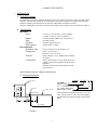
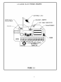
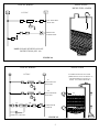
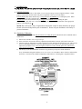
LS6000 LEVEL SWITCH
OWNERS MANUAL
♦ INSTALLATION
♦ CALIBRATION
♦ TROUBLESHOOTING
♦ WARRANTY
BABBITT
INTERNATIONAL, INC.
P.O. Box 70094
Houston, TX 77270
(713) 467-4438
TABLE OF CONTENTS
Page
1. Description
-------------------------------------------------------
1
A. General Description ---------------------------------------
1
B. Specifications -----------------------------------------------
1
2. Theory of Operation/Ordering Information
3. Installation
----------------
2
------------------------------------------------------------- 2
A. Inspection and Operation Check
--------------------------
2
B. Physical Installation
-------------------------------------------- 2
C. Removing Electronics
-------------------------------------------- 3
D. Typical Applications and Wiring Diagrams ----------------1) LS6000 Terminal Layout
2) Ladder Diagrams
4. Calibration
-----------------------------------
3
3
-------------------------------------------- 5
------------------------------------------------------------- 6
A. Fail Safe Selection
-------------------------------------------- 6
B. Sensitivity Calibration ---------------------------------------
6
5. Maintenance and Troubleshooting -------------------------------
7
6. Warranty --------------------------------------------------------------
8
LS6000 LEVEL SWITCH
1. DESCRIPTION
A. General Description
The LS6000 is a point level switch that detects the presence or absence of material in a bin, silo, tank or other
container. The basic unit is made up of a solid stainless steel probe attached to an explosion proof housing.
Inside the explosion proof housing are all calibration adjustments and sensing electronics.
The unit is calibrated in the absence of material and an internal relay changes state when material is detected.
B. Specifications
Electrical
Power:
Output:
Fuse:
Fail Safe:
RF Frequency:
Environmental
Hazardous Area:
Temperature:
Pressure:
Construction:
115 VAC (±15%) 50/60 Hz. 2 watts, standard.
(12 VDC, 24 VDC or 230 VAC optional)
2 Form C contacts, DPDT relay, 5 amp resistive
on board, 250 mA
Selectable high or low level
Approximately 1.3 MHz
Class I, Group D, Class II, Group E, F, G
Probe: -30° F to 250° F
Electronics: -40° F to 185° F
Probe: 1500 psi @ 75° F. Higher ranges available
on request.
Probe: All wetted parts, 316 SS, Delrin and Viton.
A Halar coating can be applied to the probe when
applicable.
Electronics: Housed in cast aluminum explosion
proof enclosure.
Specifications subject to change without notice.
C. Ordering Information
LS6000 – 115VAC – S – 10*
1” NPT
1” NPT
½” DIA. 316 SS
6 1/8”
5 1/8”
*This describes an LS6000, powered by a 115 VAC,
with a 316 SS probe, 10” long. The probe length is
measured from the end of the nipple to the tip of the
probe.
INSULATOR
1 7/8”
4 ¾”
Model
Supply Voltage
“S” – 316 Stainless Steel Probe
“H” – Halar Coated Probe
Probe length in inches
4”
MAX
10” Standard
Longer Lengths Available
FIGURE 6.1
1
2. THEORY OF OPERATION
The LS6000 employs a radio frequency (RF) balanced impedance bridge circuit to detect if the probe is in
contact with the material that is to be sensed.
When material is not in contact with the probe, the bridge is balanced by turning the adjustment pot to find the
threshold where the red led goes out.
When material is in contact with the probe, the bridge becomes unbalanced and the comparing circuit realizes
the change. This causes the relay to change state.
3. INSTALLATION
*CAUTION: ALL INSTALLATION AND WIRING MUST CONFORM TO NEC AND ALL OTHER
LOCAL ELECTRICAL CODES. TAKE SPECIAL CARE IN OBSERVING HAZARDOUS AREA
SAFETY PROCEDURES. WE ASSUME NO LIABILITY FOR IMPROPERLY INSTALLED OR
WIRED UNITS.
A. Inspection and Operation
After unpacking the LS6000, visually inspect the unit for any damages.
Please advise the factory or your local distributor of any damage.
Before installing the unit, a simple operational check can be performed.
On the bench, hook up the appropriate power to L1 and L2. The operating voltage of the LS6000 is marked on
the power supply board.
Hold the unit so that the probe is not touching any surface and touch the probe.
When you touch the probe, the red led should come on. This simulates product touching the probe.
B. Physical Installation
1) The LS6000 is installed into the vessel wall using a 1” NPT connection.
This can be either a threaded coupling or a tapped entry such as a flange.
2) The insulator should always extend at least 2” through the vessel wall.
3) Always check for physical room around the location you have chosen to allow for installation. Allow 3.25”
turning radius to screw the probe in and clearance above for the length of the probe.
4) CAUTION: Always take the necessary safety precautions when cutting or welding in the
coupling for the LS6000.
5)
6)
7)
8)
9)
a) Tag and lock out the electrical power to the equipment that services the vessels.
b) Check liquid or dry powders that create a gas in the vessel for oxygen as well as the explosion factor.
(All dust will explode.)
c) Vessels that are cross vented have to be isolated.
Screw the LS6000 into the connection provided. In dry material application, no sealant on threads is
required. On liquid, teflon or a good pipe thread sealant may be used.
The LS6000 has a 1” NPT conduit entry. When wiring these units, conform to the National Electrical Code
and any other city or company codes.
Always install the electrical connection to the 1” NPT conduit entry so that water will not follow the
connection routing into the threads of the conduit hub. To guarantee that condensation and water will stay
outside the unit, install an EYSM unilet before each LS6000 and fill with explosion proof sealing cement.
When required, the LS6000 probe can be bent to meet your special application. Remember to allow 2” of
clearance between the probe and the vessel wall. If the probe is to be used in a pressure application, the
factory must bend the probe to your specifications.
Location of probes on high level installations is more critical on dry material than liquids. Note the
following:
a) For dry materials, mount the LS6000 in the top of the vessel whenever possible. (This allows you to
lengthen the probe if necessary.)
b) Avoid mounting the LS6000 near the product inlet, vent return lines, dust collectors and vessel
discharge openings on dry materials. Turbulence around these areas can cause erratic detection unless
the probe is long enough. On old installations it might be wise to fill the vessel first to determine the
length or location of the probe. CAUTION: Always take safety precautions before opening
vessels for such inspection.
c)
On gravity filled vessels, take into consideration the angle of repose formed by the product.
2
d) On dry product that flows like water (starch), when using the LS6000 to stop the flow by means of a
butterfly valve or knifegate, make sure the probe is long enough to allow time to close these slow
moving valves.
e)
In small vessels where a good location is hard to find, it may be necessary to put a baffle plate between
the probe and the product inlet to keep product off of the probe as it fills.
C. Removing the Electronics
1)
2)
3)
4)
Disconnect supply power at main power source.
Disconnect wires from terminal strip.
Unplug blue antenna lead.
Remove green grounding screw.
D. Typical Applications and Wiring Diagrams
As follows:
LS6000 TERMINAL LAYOUT
5 AMP RELAY CONTACTS
•
C2
NC2 NO2 NO1 NC1 C1 L2 L1
G
SUPPLY VOLTAGE*
*NOTE: EACH LS6000 POWER SUPPLY IS INTENDED FOR ONLY ONE SUPPLY
VOLTAGE. THIS VOLTAGE IS PRINTED ON THE POWER SUPPLY BOARD.
FOR 115 VAC OR 230 VAC UNITS, HOOK UP THE HOT LEAD TO L1 AND THE NEUTRAL
TO L2, WITH APPROPRIATE GROUND.
FOR 12 VDC OR 24 VDC UNITS, HOOK THE POSITIVE VOLTAGE TO L1 AND THE
COMMON OR GROUND TO L2.
FIGURE 6.2
3
4
TYPICAL WIRING
L1
APPLICATION
HIGH LEVEL ALARM
115 VAC
L1
L2
LS6000
L2
FAIL SAFE HIGH
SELECTED.
G
NC1
R
HIGH LEVEL
ALARM LIGHT.
C1
NOTE: PLEASE REVIEW FAIL SAFE
INSTRUCTIONS, (SEC. 4A)
FIGURE 6.4
TYPICAL WIRING
L1
APPLICATION
115 VAC
L1
L2
LS6000
L2
“A”
FAIL SAFE LOW
SELECTED.
L2
“B”
FAIL SAFE HIGH
SELECTED.
AUTOMATIC FILLING OF TANK.
(WHEN LEVEL FALLS TO POINT “A”,
A PUMP COMES ON TO FILL TO
POINT “B”, THEN TURNS OFF.)
G
L1
LS6000
“B”
G
“A”
C1
“B”
NC1
C1
NO1
PUMP
PUMP MOTOR
STARTER
PUMP AUX. CONTACT
“A”
PUMP
FIGURE 6.5
5
4. CALIBRATION
PLEASE READ THE ENTIRE CALIBRATION PROCEDURE BEFORE CALIBRATING THE LS6000.
A. Fail Safe Selection
The fail safe feature provides a “false alarm” in case of power outage or major component failures. When
properly selected, the fail safe feature can protect equipment or alert you of a unit failure.
Fail Safe High (FSH) means that the relay is energized when NO PRODUCT is touching the probe. When
product comes into contact with the probe, the relay is de-energized.
Fail Safe Low (FSL) means that the relay is energized when PRODUCT IS touching the probe.
Fail Safe High or Fail Safe Low is selected by plugging the jumper near the transformer in the appropriate
position. (See diagram pg. 4 )
NOTE: Due to the wide variety of applications and possible control or alarm functions, the proper
fail safe selection will depend on your circumstances. Please call your distributor or the factory if
you need assistance.
B. Sensitivity Calibration
The LS6000 should be calibrated when no material is touching the probe and when the unit is installed where it
will be used.
1) Observe the red LED. If it is on, go to step 3.
2) If the red LED is off, turn the sensitivity adjustment potentiometer clockwise (CW) until it comes on.
3) Turn the sensitivity adjustment pot counter-clockwise (CCW) until the red LED just goes out. This sets the
unit to its maximum sensitivity. If in your application this is too sensitive, you can turn the sensitivity
adjustment pot further CCW. Always bring the product into contact with the probe after calibration to
assure proper performance.
4) The factory or your local distributor can answer any questions you may have about calibration.
Every LS6000 has a diagram inside the screw cover to serve as a reminder to those who have calibrated the
unit before. This shows the calibration adjustments and indicators. This diagram is reproduced below.
FIGURE 6.6
6
SPECIAL CALIBRATION NOTES:
For some products, the LS6000 can be calibrated with product touching the probe. To do this, turn the
sensitivity adjust pot CW until the red LED just comes on and continue CW for 1/8 to ¼ of a turn. Always
check to see if the unit resets in the absence of product.
INTERFACE CALIBRATION
For applications such as an oily water interface, the unit should be calibrated in the less electrically
conductive fluid (oil) and the unit will then “ignore” the oil, but sense the water.
5. MAINTENANCE AND TROUBLESHOOTING
No routine maintenance is required other than keeping the interior of the unit clean and free of dirt, dust and other
contaminants.
The LS6000 consists of three main sub-assemblies. These are the enclosure, the antenna probe and the electronics.
The following troubleshooting guide will assist in determining how to correct most of the problems which may
occur in sections 3 and 4.
PROBLEM
POSSIBLE CAUSE
SOLUTION
RED LED cannot be adjusted to
turn on.
Antenna lead not connected
No power to unit.
Bad electronic card.
Antenna probe is shorted to case
or ground.
Plug antenna lead into probe.
Check for correct power to unit.
Repair or replace card.
Unplug banana plug and position
it so that the bare end is not
touching anything. Turn
calibration pot 20 turns CCW.
LED should go out. If it does,
repair, replace or clean antenna
probe. If LED does not go out,
replace electronics.
Unit triggers when material
touches probe, but will not reset
when material recedes from probe
or unit and gives false alarm.
Bad sensing card.
Improper mount of probe.
Improper calibration procedure.
Excessive material build-up on
probe.
Unit will not detect material.
Probe is mounted in flow of
material.
Improper calibration.
Repair or replace card.
Contact factory or dist.
See section 4B.
Perform “dirty probe calibration”:
Recalibrate with built up material
on probe. See section 4B.
Revise mounting.
Unit will not stay in calibration.
Relay operates properly, but no
signal at terminals.
Antenna lead not plugged into
probe.
Unit was calibrated with material
touching probe.
Poor grounding of unit to vessel.
Burned or broken lands on the
printed circuit board.
RED LED remains on at all times
Bad relay contacts.
See calibration instructions,
section 4.
Plug antenna lead into probe.
Be sure material is not touching
probe and recalibrate.
Provide secure ground connection.
Turn off power. Remove module
from housing and inspect lands on
printed circuit for damage.
Replace if necessary.
Replace relay or return for repair.
PLEASE CONTACT THE FACTORY OR YOUR DISTRIBUTOR IF YOU HAVE ANY
QUESTIONS OR NEED ASSISTANCE.
7
6. WARRANTY
All components of the LS6000 are warranted to be free from defects in material and workmanship for a
period of two years from the date of purchase . This warranty applies to general purchaser and to
components installed, serviced and operated according to instructions.
Babbitt International, Inc. will repair or replace, at its option, FOB at its plant or any other location
designated, any part which proves to be defective in manufacture or workmanship.
All claims must be made in writing within the warranty period. No claims outside of the warranty period
will be honored.
Warranties are not applied to any components which have been damaged by improper installation, use,
exposure to unusual atmospheric conditions or components which have been misused, abused, damaged
by neglect or accident. This warranty shall not apply to any components which have been altered or
repaired without the prior written consent of Babbitt International, Inc.
Babbitt International, Inc. assumes no responsibility or liability for any labor or material back charges,
without written authorization. Any products returned must be with prior written authorization.
THE FOREGOING IS IN LIEU OF ALL OTHER WARRANTIES, EXPRESSED OR IMPLIED,
INCLUDING ANY WARRANTIES OF MERCHANTABILITY AND/OR FOR FITNESS FOR
PARTICULAR PURPOSE, AND BABBITT INTERNATIONAL, INC. ASSUMES NO OTHER
LIABILITIES EXPRESSED OR IMPLIED. BABBITT INTERNATIONAL, INC. SHALL NOT BE
LIABLE FOR NORMAL WEAR AND TEAR, NOR FOR DIRECT, INCIDENTIAL OR
CONSEQUENTIAL DAMAGES. IN NO EVENT SHALL BABBITT INTERNATIONAL
INCORPORATED’S LIABILITY EXCEED THE PRICE OF ITS PRODUCT AT THE TIME OF
PURCHASE.
8