1
FriendlyNET® VR2004 Series
VPN Security Routers
User’s Manual
Before You Start
Thank you for purchasing the Asanté FriendlyNET VR2004 Series
VPN Security Router. Your router has been designed to provide a
lifetime of trouble-free operation. However, to ensure a smooth installation, you must have the following items before you begin:
•
•
•
•
•
•
Internet connection: Valid ISP account and Cable/DSL modem with 10BaseT Ethernet port. Peripheral port for back
up dial-up (v.90 or ISDN TA) modem included (Contact
your ISP if you have problems verifying that you have a
working Internet connection)
Network connection: Built-in 10/100 Fast Ethernet port or
10/100 Fast Ethernet network adapter for each computer
sharing the Internet connection
Cables: 10BaseT or 100BaseTX Fast Ethernet cables to
connect computers to the router
Client operating system: Client must be capable of accepting an IP address from a DHCP server. Supported operating systems include Apple Mac OS 9 and higher, Microsoft
Windows 98/ME/2000/XP Home or Professional, Red Hat
Linux
Network protocol: TCP/IP network protocol for each client
Web browser: Microsoft Internet Explorer or Netscape
Communicator, version 4.0 or later, or Apple Safari
The following devices are not compatible with the VR2004 Series
routers: Cable/DSL modems with USB or Firewire connections,
asymmetrical dual media connections, Home PNA or other nonEthernet compatible communication devices.
2
FriendlyNET VPN Security Router
Quick Start Guide
This section will guide you through setting up the Asanté
FriendlyNET router with your Cable/DSL modem. Setting up your
router requires three basic steps:
1.
2.
3.
Determine the TCP/IP settings for your computer and record
them in the table provided.
Set up your hardware. You MUST power up the router FIRST
after attaching any devices to the router.
Configure your router.
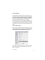
1. Determine Your TCP/IP Settings
You should already have a working Internet connection using a Cable/DSL modem. First you must collect the TCP/IP settings from
your computer and your Internet Service Provider (ISP). This information will be used to configure your new router and any additional
computers you wish to add to your new network. The following sections explain how to collect your TCP/IP settings for Macintosh,
Windows, and Linux platforms.
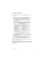
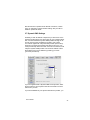
Mac OS 9
1.
2.
3.
Open your computer’s TCP/IP control panel found under the
Apple menu.
For Connect via, verify that either Ethernet built-in or the
Ethernet adapter installed in your Mac is chosen.
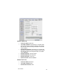
Complete the information in the Your Settings portion of the
table below.
User’s Manual
3
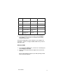
Item No.
TCP/IP Control Panel
Description
1
Configure Manually or
Using DHCP Server
Static IP Address or
Dynamic IP Address
2
IP Address
WAN IP Address
3
Subnet Mask
WAN Subnet Mask
4
Router Address
WAN Gateway
5
Name Server Address
Primary and Secondary
DNS
6
Host Name (DHCP Server Client ID No.
Only)
4.
Your Setting
Once the information has been recorded, choose Using DHCP
Server from the Configure: pull-down menu. Close the dialog
box and save your changes.
Repeat steps 1, 2, and 4 to configure additional Macs you wish to
add to the router.
Mac OS X
1.
2.
3.
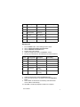
4
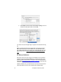
Go to System Preferences on your desktop and select Network. In the Network screen that appears, select Show: Active
Network Ports and click the box to choose the PCI Ethernet
card slot where your network card is installed.
Click the Apply Now button. The next screen will show the options for your network settings. Be sure that the TCP/IP tab is
selected.
Before changing your configuration, complete the information in
the Your Settings portion of the table below, and save for future reference.
FriendlyNET VPN Security Router
4.
Item No.
TCP/IP Control Panel
Description
1
Configure Manually or
Using DHCP Server
Static IP Address or
Dynamic IP Address
2
IP Address
WAN IP Address
3
Subnet Mask
WAN Subnet Mask
4
Router Address
WAN Gateway
5
Name Server Address
Primary and Secondary DNS
6
Host Name (DHCP
Server Only)
Client ID No.
Your Setting
Once the information has been recorded, select Configure:
Using DHCP. You will receive an IP address automatically
from your DHCP server.
The TCP/IP configuration of your computer is now complete. Repeat steps 1, 2 and 4 to configure additional Macs that you wish to
add to the router.
Windows 98/Me
1.
2.
From the Windows Start button, choose Run. In the dialog box,
type winipcfg and click OK.
Choose your computer’s Ethernet adapter from the first dropdown list.
Tip: The PPP setting is usually for your dial-up analog modem.
Don’t choose this selection.
User’s Manual
5
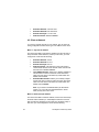
3.
4.
Expand this dialog box by clicking on the More Info >> button.
Complete the information in this table:
Item No.
IP Configuration
Description
1
Host Name
Host Name
2
DNS Servers
Primary DNS
3
Your Setting
Secondary
4
Adapter Address
MAC Address
5
IP Address
WAN IP Address
6
Subnet Mask
WAN Subnet Mask
7
Default Gateway
WAN Gateway
Tip: Next to the DNS Servers field, click the button to show the
Secondary DNS (if available).
5.
6.
7.
8.
From the Windows Start button, choose Settings and select
Control Panel. Double-click the Network icon.
In the Configuration tab, highlight the TCP/IP protocol line associated with your network card adapter.
Click Properties to open the TCP/IP Properties dialog. Click the
IP Address tab. Select Obtain an IP address automatically.
Click OK.
Click OK again. Windows will begin copying files to your computer. Click Yes to restart your computer with the new settings.
Repeat steps 1-3 and 5-8 to configure additional PCs on your network.
Note: Keep your Windows CD handy. You may be asked to insert it
so that Windows can copy necessary files.
Windows NT/2000
1.
2.
3.
6
From the Windows Start button, choose Run. In the dialog box,
type command and click OK.
At the command line, type the command ipconfig /all and
press Enter.
Fill in the table below with the data from the screen.
FriendlyNET VPN Security Router
Item No.
IP Configuration
Description
1
Host Name
Host Name
2
Primary DNS
Primary DNS
3
Physical Address
MAC Address
4
IP Address
WAN IP Address
5
Subnet Mask
WAN Subnet Mask
6
Default Gateway
WAN Gateway
Your Setting
Windows XP
1.
2.
3.
4.
5.
6.
From the Start button, select Settings/Control Panel.
Click on Network and Internet Connections.
Click the Network Connections icon.
Double-click on the network.
Under the Support tab, click on the Details… button.
Record your information on the table below for future reference.
Item No.
IP Configuration Description
1
Physical Address
MAC Address
2
IP Address
WAN IP Address
3
Subnet Mask
WAN Subnet Mask
4
Default Gateway
WAN Gateway
5
DNS Servers
Primary
Secondary
6
WINS Servers
Primary
Secondary
Your Setting
7.
8.
Under the General tab, click the Properties button.
Select the Internet Protocol (TCP/IP) and click the Properties
button.
9. Select Obtain an IP Address automatically and Obtain DNS
server address automatically.
10. Click OK. You will be prompted to restart your computer.
User’s Manual
7
The TCP/IP configuration of your computer is now complete. Repeat steps 1 – 4 and 7 – 10 to configure additional PCs on your network.
Red Hat Linux
In order to gather the information necessary to complete the table,
you will need to run the /sbin/ipconfig command. You will also
need to examine the following files:
•
•
/etc/sysconfig/network
/etc/resolv.conf.
Please refer to your Linux documentation for information on accessing these files.
2. Install The Hardware
Follow these steps to connect the router to your network:
1.
2.
3.
4.
5.
8
Turn the power off to your computers, modem and the router.
Connect an Ethernet cable from your Cable/DSL modem to the
router’s WAN port.
Connect an Ethernet cable from your computer’s Ethernet port
to one of the LAN ports on the router. Repeat the process to
connect other computers to the router. If you have more computers to add than you have router ports, simply add a hub or
switch to one of the router ports. This creates additional available ports.
Optional: Use a DB-9 to DB-25 serial cable to connect a
straight through modem cable from your external backup modem to the router’s COM port.
Turn on the power to the router FIRST, and let it power up. The
router will enter a self-test mode where the status light will blink
for a few seconds and then stop. The router is ready for operation. Now you may turn on the power to the devices that are
attached to the router.
FriendlyNET VPN Security Router
3. Configure Your Router
From your computer, use your browser to configure the router for
your network.
1.
2.
3.
4.
5.
6.
Start your web browser. Type http://192.168.123.254 into your
browser’s address or location field and press Enter.
In a few moments you’ll see the Login screen for the router.
Enter the default username, admin (the default password is
blank), and click OK.
Click the Setup Wizard button from the top of the page.
Step through the configuration screens along the left side of the
Setup Wizard page.
Enter the required values for the WAN type you will use.
Be sure to save your configuration and restart the router from
the Save & Restart page in the Setup Wizard.
The basic configuration of your Asanté router is now complete. See
Chapters 2, 3 and 4 for more details.
Note: By default, the password for the router is blank. We strongly
recommend that you assign a password to your router. See page 35
for more details.
User’s Manual
9
10
FriendlyNET VPN Security Router
Table of Contents
Before You Start
Quick Start Guide
2
3
Chapter 1. Introduction
Chapter 2. Configuration
Chapter 3. Advanced Settings
Chapter 4. VPN Configuration
13
17
27
41
Appendix A. Warranty Statement and FriendlyCare
Support
Appendix B. FCC Statement
Appendix C. Troubleshooting
Appendix D. Renewing Client IP Addresses
Appendix E. Service Ports
Appendix F. Hardware and Software Compatibility
Appendix G. Specifications
Appendix H. Configuring a System Log Server
Appendix I. Your 802.11b Wireless Network
51
53
55
59
61
63
65
69
73
User’s Manual
11
12
FriendlyNET VPN Security Router
Chapter 1. Introduction
Thank you for purchasing the FriendlyNET VR2004 Series VPN Security Router. The router provides an easy, affordable way to communicate over the Internet, while ensuring a secure connection to
another VR2004 (or other compatible VPN solution). Whenever
data is intended for the remote site, the router automatically encrypts the data and sends it to the remote site over the Internet,
where it is automatically decrypted and forwarded to the intended
destination.
The FriendlyNET VR2004 is available in two configurations:
•
•
VR2004C: Router with 4-port 10/100 LAN ports and
backup modem port
VR2004AC: Router with 4-port 10/100 LAN ports and
backup modem port, plus integrated 802.11b wireless access point
1.1 Features
Key features of the router include:
•
•
•
•
•
•
Cable/DSL Modem Support: The router is compatible
with all major brands of Cable/DSL modem
Asynchronous Port: A dial-up modem (not included) can
be attached to the router to automatically provide a backup
connection should the Cable/DSL connection fail
DHCP Server: Automatically assigns IP information to network users
DHCP Client: Automatically gets IP information from the
ISP DHCP server
Firewall Protection: Built-in NAT firewall provides network
security
IP Sharing: Supports unrestricted Internet access for each
network user at all times
User’s Manual
13
•
•
•
•
•
•
•
Hacker Attack Logging: Supports general hacker attack
pattern monitoring and logging
High Performance 32-bit RISC CPU Engine: With the
most advanced 32-bit RISC CPU engine, the router has
full compatibility with present and future Cable/DSL technologies
PPPoE Client: Supports PPPoE client function to connect
to the remote PPPoE server
Virtual Server: Allows an internal server to be accessible
from the Internet
Upgradeable: Allows new features to be added in the future
VPN Support: Supports L2TP pass-through function
IPSec Security:
◊
◊
◊
◊
◊
◊
◊
◊
•
•
•
•
•
14
Authentication (MD5 / SHA-1)
DES/3DES Encryption, IP Encapsulating Security
Payload (ESP)
Internet Security Association and Key Management
Protocol
Internet IP Security Domain of Interpretation for
ISAKMP
The NULL Encryption Algorithm and its use with IPSec
8 IPSec Tunnels
IPSec LAN to LAN
IPSec Client to LAN
PPTP Support: Support PPTP (Point-to-Point Tunneling
Protocol) function
Idle Timer: Lets you set a specified idle-time before automatically disconnecting
Routing Protocol: Supports static route, RIP versions 1
and 2
Dial-on Demand: Eliminates the need for manual Dial-up
and automatically logs in to your ISP
Web-Based Configuration: Configure your router from
any standard web browser
FriendlyNET VPN Security Router
•
DMZ (Demilitarized Zone): Allows you to place one server
or workstation outside the firewall, to allow outside parties
unrestricted access to the server
1.2 Package Contents
Please compare the items included in your package to the list below. The following items should be included:
•
•
•
FriendlyNET VR2004 Series VPN Security Router
Power adapter
User’s Manual (this document)
If any of the above items are damaged or missing, please contact
your dealer immediately.
1.3 System Requirements
Before installing the router, you will have need to have met the following requirements:
•
•
•
•
•
•
Microsoft I.E 4.0 or later version, Netscape Navigator 4.0
or later version, or Apple Safari
One computer with an built in or installed 10 Mbps, 100
Mbps or 10/100 Mbps Ethernet port
Optional: One Analog Modem or ISDN TA (if a dialup connection is needed)
One RJ-45 Cable/DSL Internet connection
TCP/IP protocol installed
UTP network cable (Category 5 or better) with a RJ-45
connection
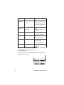
1.4 Front and Rear Panel Descriptions
The front panel of the router contains the LED Indicators for easy
monitoring and troubleshooting of its functioning.
Consult the table below for a description of the LED Indicators.
User’s Manual
15
LED
Link/Activity
LAN ports 1 to 4
Color
Green
Blinking
Off
Description
A valid link has been established on
the port.
Port is transmitting or receiving packets.
No link has been established on the
port.
Wireless
(VR2004AC model
only)
Green
COM
Green
A valid link has been established.
Off
No link has been established.
Green
A valid link has been established.
Off
No link has been established.
Blinking Yellow
The router is booting up, or a firmware
upgrade is taking place.
Off
The router is operating normally.
Red
The power is on.
Off
The power is off.
Internet
Status
Power
Blinking Green
A wireless connection has been established.
A wireless connection has not been
established.
Table 1-1 LED Description
From left to right, the rear panel of the router
contains the following:
Power (5 VDC) plug; Internet (WAN) port; COM port; Reset button;
and LAN ports 4, 3, 2 and 1.
16
FriendlyNET VPN Security Router
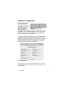
Chapter 2. Configuration
Power up the router first,
before powering up the attached devices. Launch
your web browser and type
the default IP address
(192.168.123.254) in the
browser’s address box.
Press Enter. The login window will appear. Type the default username admin and press OK. By default, the password for the router
is blank. We strongly recommend that you assign a password to
your router. See page 35 for more details.
The main menu will appear (screens shown are from both models—
the Wireless Settings page will not appear in screenshots from the
VR2004C model). Click on the buttons across the top to access the
available configuration pages. Within each page, click on the buttons along the left side to access further pages for configuration
(see the sections that follow for more details).
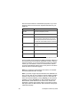
2.1 Setup Wizard
From the main menu, click on the corresponding button to access
the Setup Wizard screen. From this screen, it is possible to configure the following:
User’s Manual
17
•
•
•
•
•
•
Time Zone Settings
Device IP Settings
ISP Settings
Additional ISP Settings
Modem Settings
VPN Settings
Important! You must save and restart the router in the Save & Restart screen for your configurations to take effect.
2.1.1 Time Zone Settings
From the drop down menu, choose the local time zone. Click Next
to enter the data and to proceed to Device IP Settings.
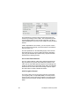
2.1.2 Device IP Settings
To prevent unauthorized access to the router, you should change
the device’s default IP address on your network. This is the internal
LAN IP Address, and NOT the WAN IP Address from your ISP.
Click Next to enter the new values and to proceed to ISP Settings.
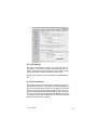
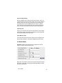
2.1.3 ISP Settings
If your ISP requires that you use a static IP Address, check the
Static IP radio button to enable it. If you enable the Static IP Address, you must then complete the fields with the information provided by your ISP (use the information that you recorded in the
18
FriendlyNET VPN Security Router
Quick Start Guide), and click Next to enter the data. If you use a
dynamic IP Address, check the Dynamic IP radio button and click
Next to continue to Additional ISP Settings.
2.1.4 Additional ISP Settings
In this page, you can enable the type of WAN connection you are
using. Your ISP may require you to use any of PPPoE, PPTP or
AT&T-like authentication.
User’s Manual
19
ISPs use the information for authentication purposes, so you must
select the check box and enter the requested information for your
WAN type.
Item
Description
User Name
Account name (assigned by your ISP).
Password
Password for the account (assigned by your ISP).
Idle Time
Router attempts to keep the connection on (“keep alive”)
until it has reached a specified idle time; enter a 0 to disable the keep alive feature. Some services will disconnect
the modem when it has exceeded a maximum session time
Enable PPTP Client
If you have a PPTP connection, check this box to enable
PPTP client.
My IP Address
The IP address provided to you by your ISP
Server IP Address
The IP address of the PPTP server provided by your ISP
Connection ID/Name
Optional (Enter the connection ID if your ISP requires it)
PPPoE/PPTP Connection
Some providers require the Ethernet address (the MAC address) of
the computer that is connecting the Cable/DSL modem to authenticate the connection. If you are connecting the router to the modem
instead, you must select the check box for Device MAC Address
and enter the WAN MAC address of the router (found in the Device
Status and Device Information pages).
Note: Do not enter the colons between the numbers, as the fields
are already separated within the page.
Note: If you have a single computer attached to the Cable/DSL modem, you may also use your computer’s network adapter card MAC
Address to allow access to the Internet. Find your card’s MAC Address from Windows 98/Me by running winipcfg, or from Windows
2000/NT by running ipconfig /all. To find a Macintosh's Ethernet
MAC address, select "Get Info” from the File menu of either the
AppleTalk or TCP/IP Control Panel. Again, do not enter the colons
that appear within the MAC address, as the fields are already separated within the page.
20
FriendlyNET VPN Security Router
Click Next to enter the new data and to proceed to the Wireless
Settings page (VR2004AC model only) or to the Modem Settings
page.
2.1.5 Wireless Settings (VR2004AC only)
The VR2004AC is designed to function as a wireless access point
using the default settings shown. If you wish to use more than one
router in your wireless network, you have the option of having one
network with multiple access points (routers), or separate networks.
If you wish to have one big wireless network, leave the SSID and
channel settings for each router at the factory default.
•
•
SSID (Service Set Identifier): An alpha-numeric name used
for identification; the Wireless stations must match the access point’s SSID
Channel: All Wireless stations must use the same channel
as the access points
If you wish to have each router in its own network and wish to keep
the networks separate, however, you will need to designate a
unique SSID for each router. Enter a unique number from 1 to 11 in
the Channel field.
User’s Manual
21
Encryption
Most internal LAN traffic does not require additional security measures. If you are transferring sensitive files or other material over the
wireless LAN, you may enable the WEP Security Settings. WEP
stands for "Wired Equivalent Protocol".
Click on either the "40(64) bit" or the "128-bit” radio button to select
which Shared Key you will use, and enter a 10 digit hexadecimal
number into the Key 1 field. Hexadecimal numbers may be alphanumeric (numerals 0-9 or letters a-f).
Note: Most wireless network cards utilize the 64-bit algorithm, including the Apple Airport card.
Note: Up to 4 WEP Keys may be configured. Each Key number
must be different. Each client must also use the active WEP key to
access the wireless network (the default key is 1).
WEP Security and Apple Airport Wireless Cards
The Apple Airport Wireless Card and the router enter and store the
WEP Security Key differently. From the Airport icon on your computer’s control strip, select the router, and enter $ plus the WEP key
in the password field.
Click Next to enter the new data and to proceed to the Modem Settings page.
2.1.6 Modem Settings
You can configure the router to use a dialup modem if there isn’t a
cable/DSL connection, or as a backup for the cable/DSL connection. To use the modem dialup, you must select the check box to
enable the modem settings function and enter the required information.
Enter the External IP Address only if your ISP requires it, otherwise
leave it at the default settings (0.0.0.0). Enter the desired settings
for the modem. Refer to the modem’s manual for more help in
changing settings.
When you have completed the configuration, click Next to enter the
data and to proceed to VPN Settings.
22
FriendlyNET VPN Security Router
2.1.7 VPN Settings
The router can be used as an ordinary unencrypted connection to
the Internet, or as a secure connection to another VPN router. To
set up a Virtual Private Network (VPN), you must enable the VPN
feature, which allows a secure connection to the Internet.
Please refer to Chapter 4. VPN Configuration for detailed information.
2.1.8 Save and Restart
After stepping through the Setup Wizard’s configuration pages, you
must save and restart the router through the Save & Restart page.
This process will take a few moments. The progress bar across the
bottom of the screen shows when the process is 100% complete.
Also, the status LED will blink while the device restarts. The router
is ready to proceed when it stops blinking. Do NOT turn off the device until the progress bar completes its cycle, the status LED stops
blinking and the Main Menu appears.
User’s Manual
23
2.2 Device Information
This page displays the current settings of the router:
•
•
•
•
•
Device Name: The host name of the router
IP Address: The IP address of the router
LAN MAC Address: The MAC address of the router’s LAN
port
WAN MAC Address: The MAC address of the router’s
WAN Ethernet port
Firmware Version: The current firmware installed
2.3 Device Status
This page displays the current connection status of the router, and
refreshes itself about every 14 seconds. Arrows are used to indicate
the state of the connections to the router:
•
•
Up and running: ------------------->
Not working: ---------l l ------------>
From this page you can view the VPN and DHCP status, as well as
release and renew IP addresses.
•
•
24
Release: Release the WAN IP address
Renew: Renew the WAN IP address
FriendlyNET VPN Security Router
•
•
VPN Status: View the IPSec Connection Status for VPN
tunnels
DHCP Status: Click to refresh the DHCP log
2.4 System Tools
From the Main Menu, select the System Tools button to display the status
of the router. The following pages are accessible from the System Tools
page:
•
•
•
•
•
Intruder Detection Log: Displays security incidents (hacker
attacks) that have occurred
Display Routing Table: Displays the current routing table,
whether entries are static or dynamic
System Status: Displays the router’s current configurations
and checks router functioning
Save Settings: Allows the current configuration to be saved
to a file
Load Settings: Allows you to load the default settings, or to
load settings from a file
User’s Manual
25
•
•
26
Upgrade Firmware: Allows you to upgrade the router to the
latest version of firmware
Reset Device: Restarts the router
FriendlyNET VPN Security Router
Chapter 3. Advanced Settings
From the main menu, click on the corresponding button to access the
Advanced Settings screen. From here, you can access the following
pages for configuration:
•
•
•
•
•
•
•
•
•
DHCP Server Settings
Virtual Server Settings
Wireless Access Control
Routing Settings
Filter Settings
Administration Settings
Dynamic DNS Settings
URL Filter Settings
E-mail Alert
Note: You may be asked to re-enter the username admin and password before entering the Advanced Settings page (the default is no
password). It is highly recommended that you change this setting to
prevent unauthorized access to the router (see Chapter 3.6).
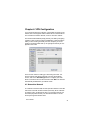
3.1 DHCP Server Settings
The router’s DHCP server is enabled by default. If you will be connecting the LAN ports of your router to an existing network which already
has a functioning DHCP server, you must be sure to uncheck the box
(shown below) to disable DHCP.
User’s Manual
27
IP Address Pool Range
This pool contains the range of IP addresses that will automatically
be assigned to the clients on your network. The default setting is
192.168.123.2 to 192.168.123.100. Increase the range if you have
more than 98 computers on your network.
IP Address Reservation
You can configure client computers with static addresses outside
the range of the router’s DHCP server, or use this option to provide
fixed (static) IP addresses to devices on your network, such as
printers or computers. If they are in the reservation table, they will
be guaranteed the same IP address each time they connect to the
router.
•
•
MAC Address: Enter the MAC address of the device or
computer
IP Address: Enter the IP address that you want to reserve
3.2 Virtual Server Settings
* This feature should only be used by users with an extensive
knowledge of TCP/IP.
One of the more powerful features of the router is the Virtual Server
feature. For a small business with two or more Internet servers, the
router can balance the workload between multiple machines. For
example, if your network server is overloaded, you can delegate
specific network services to two or more machines. For example, if
you had three servers, you could dedicate one server to handle
each of these services:
•
•
•
Port 80 (HTTP) web server
Port 53 (DNS) name server
Port 500 (VPN) direct connection to virtual private network
Of course each server must have the appropriate software installed
to handle the specific service.
28
FriendlyNET VPN Security Router
Enter the IP addresses of the network servers and the Service Port
Range to allow remote access to the desired ports. The Server Port
is a TCP or UDP port number. See Appendix E for a list of common
service ports.
A single server or workstation can be placed outside the protective
firewall to allow unrestricted access to the server and to ensure
complete Internet application compatibility, even if specified ports
are not known. To enable the DMZ (Demilitarized Zone) function,
enter the IP address of the client into the DMZ IP address field. The
function is disabled if the IP value is left at zero (0).
Important! Enabling this option will allow the server or workstation
to be unprotected from unauthorized access or infection.
User’s Manual
29
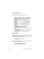
3.3 Wireless Access Control Settings
* This feature should only be used by users with an extensive
knowledge of TCP/IP.
By default, all users on the router have full access to local and wide
area networks. If necessary, network managers can control LAN
and WAN access by entering the MAC addresses of clients into a
table.
From the pull-down menu you may select the following:
•
•
•
Disable Access Control: Any user with the correct wireless settings has access to the wireless network
Enable Grant Access List: Any user who is on the Grant
Access list and has the correct wireless settings has access to the wireless network
Enable Deny Access List: Any user who is on the Deny
Access list is denied access to the wireless network
If you select Enable Grant Access List or Enable Deny Access List,
a screen like the following one will appear. For each user you wish
to add to the respective lists, enter the MAC address of their wireless network adapter and click Add.
30
FriendlyNET VPN Security Router
To delete a MAC address, select the corresponding checkbox and
click the Del button. The maximum number of entries allowed in the
table is 32.
Note: At least one client must have full access in order to perform
administrative tasks.
Click Submit to have your changes take effect.
3.4 Routing Settings
* This feature should only be used by users with an extensive
knowledge of TCP/IP.
This screen allows you to enter the Static and Dynamic Routing settings.
3.4.1 Static Routing Table
Network traffic sent by the router is ordinarily sent to the default
gateway configured when the router is set up. Occasionally you
may need to specify a different gateway for a particular IP network.
User’s Manual
31
To specify that gateway you need to define a static route.
•
•
•
Destination IP Address: The network address of the remote network
Subnet Mask: The subnet mask of the remote network
Gateway IP Address: The IP address to be used as a gateway to the remote network
3.4.2 Dynamic Routing Settings
The router is capable of exchanging routing information with other
routers on a LAN. It does this by exchanging packets using the
Routing Information Protocol (RIP).
If you install the router on a network with other routers, your Network Administrator may want to turn on this feature. Unless your
Network Administrator asks you to use RIP, you should leave this
option disabled.
32
FriendlyNET VPN Security Router
3.5 Filter Settings
Filter Settings give you additional control over what users on your
local network can see on the Internet, or what users on the Internet
can connect to on your local network. LAN filters control what resources on the Internet your local users can connect to. WAN filters
allow extra control (beyond what the built-in firewall provides) over
what users on the Internet can see on your local network.
LAN and WAN filters may be enabled separately. By default they
are both disabled. Both the LAN and the WAN filters have a default
policy—either to allow all traffic or to block all traffic. After configuring the defaults you can then add rules that make exceptions to the
default.
3.5.1 LAN Filter Settings
Since the router’s primary purpose is to allow several computers to
share an Internet connection, most users will configure a LAN filter
to allow all access. But you may want to restrict some users on your
LAN so that they don’t have complete access to the Internet.
For example, you may want to keep some of your users from using
Usenet. Usenet uses NNTP (Network News Transfer Protocol)
which runs on port 119.
User’s Manual
33
Your selections should look like this:
•
•
•
•
•
•
LAN Side Filter Enabled: Enabled
Default LAN Side Filter: Pass
Filter Entry: Block
Protocol: TCP
IP Address Range: 192.168.123.10 to 192.168.123.20
Destination Port Range: 119-119
Click Save to add the filter rule (to delete a filter rule, check the “del”
box and click the del button).
This filter will prevent any LAN user whose IP address is in the indicated range from using NNTP.
3.5.2 WAN Filter Settings
Next, access the WAN Filter Settings page by selecting the button
from the left-side menu. A WAN Filter works similarly to the LAN
Filter. If, for example, you need to run a web server from behind
your firewall at your home office, but you only want people in your
main office to be able to connect to it, you would want to make the
default policy of your WAN Filter Block.
Your setting would look something like this:
•
•
•
•
•
•
WAN Side Filter Enabled: Enabled
Default WAN Side Filter: Block
Filter Entry: Pass
Protocol: TCP
IP Address Range: 172.16.203.1 to 172.16.203.254
Destination Port Range: 80-80 (HTTP)
Click Save to add the filter rule. These settings will allow people in
your office (where the IP addresses are in the range indicated) to
connect to your web server (since web servers use TCP port 80),
but will not allow anyone else to connect.
34
FriendlyNET VPN Security Router
3.6 Administrative Settings
In this screen, you can set several administrative options for the
router simply by entering a password or checking various options
that are listed.
3.6.1 Password Settings
To prevent unauthorized access to the router, it is highly recommended that you change from no password (default) to a password
of your choosing, and keep it in a safe place. Simply enter the new
password in the New Password field and retype it for verification.
Note: If you lose or forget your password, you can reset the router
to its default settings by pressing the small reset button located on
the back of the router. Use a pen or similar tool to press the reset
button for 5-6 seconds. All configurations will be reset to the default
settings, and you will need to re-enter all of your configurations.
User’s Manual
35
3.6.2 Remote System Administration
You may configure your router to allow a user on the Internet to administer it. The default setting 0.0.0.0 means that a user from any IP
address may administer the router. You should carefully consider
the possible security risks of leaving this setting at the default. It is
safer to enter the IP address of a known computer on the Internet.
For example, you may set up the router so that you are able to administer it from your computer at work.
If you change the port number for the router’s web interface, you will
have to add the new port number to the address you type into your
web browser in order to connect to the router:
http://192.168.123.254:1023 if you have changed to port number to
1023.
By default, any remote user can ping the router. Uncheck the box to
ignore ping requests.
3.6.3 System Log
Because the router’s memory cannot hold as many messages as a
computer with a hard drive, you can have the router send its System Log messages to another computer (or server) on the network.
Check the Enable box to enable the System Log function and enter
the log server IP address. (Note: The ability to receive system log
messages is most common on Unix-type systems. Shareware versions of system loggers are available for other operating systems at
most of the popular websites, e.g., www.tucows.com. Please refer
to Appendix H for more information on system logging on your
server.)
3.6.4 Miscellaneous
By default, the router is forced to reconnect PPPoE if packets cannot be sent or received from the connection. Click the check box to
disable the forced-reconnect feature.
3.6.5 System Parameters
The system parameters allows you to set up the Maximum Transmission Unit (MTU) value. Click on the check box to enable the
MTU settings. The default MTU value is 1500. In some areas, the
36
FriendlyNET VPN Security Router
ISP sets the limit on packet size for PPPoE connection, in which
case, you will have to change the MTU setting. See your ISP for
details on packet size limits.
3.7 Dynamic DNS Settings
Ordinarily, a static IP address is required if you want users on the
Internet to be able to find you with a name for your computer rather
than a numerical address. Dynamic DNS providers arrange for users who get a dynamic IP address to be able to use a name.
You need to register with a Dynamic DNS provider (see the dropdown list in the page shown below) and select a name (i.e. yourname.provider.net). When the router connects to the Internet, it will
notify the Dynamic DNS provider of its current IP address. Users
will be able to find your IP address by providing your name
(yourname.provider.net).
If you are registered with a Dynamic DNS service provider, select
the check box for Use a dynamic DNS service and fill in the information from your ISP.
If you have DYNDNS as your dynamic DNS service provider, you
User’s Manual
37
may enable the Use wildcards feature.
3.8 URL Filter Settings
This feature allows you to block access to certain websites on the
Internet. You can specify words or letters that, if they appear in the
website name (the URL) or newsgroup name, will cause the site to
be blocked by the router.
Click the check box to enable the URL Filter function, and enter a
key word into the Filter String field. Press Add. After entering all of
the desired strings, click Submit to enter the data.
3.9 E-mail Alert
The router can be set to periodically E-mail you a log of internal security events, such as denied incoming service requests and administrator logins, or when a client on the LAN attempts to visit a
blocked website.
38
FriendlyNET VPN Security Router
To enable this feature, access the E-mail Alert screen from the Advanced Settings page and check the box Enable E-mail Notification. Next, enter the IP address of the outgoing mail server and the
destination e-mail address in the given fields and select the frequency for receiving E-mail alerts.
3.10 Save and Restart
Each time you submit or add or change data, the Save & Restart
page will appear. To continue configuration, select the appropriate
option to be taken back to that page. When you are finished, however, be sure to click on Save & Restart (accessed through the
Setup Wizard page). Do NOT turn off the device until the progress
bar completes its cycle, the status LED stops blinking and the main
menu appears.
User’s Manual
39
40
FriendlyNET VPN Security Router
Chapter 4. VPN Configuration
If you require more than an ordinary, unencrypted connection to the
Internet, the router supports IPSec to allow secure communications
from a network to another network, or from a client to a network.
The Virtual Private Network (VPN) protects your data by encrypting
it while it is sent across the Internet. Additionally, it assures that the
traffic you are receiving is actually from the computer you are expecting to exchange traffic with. Up to eight (8) tunnels may be configured on the router.
There are two modes for setting up a VPN using the router: network-to-network and client-to-network. From the Setup Wizard
screen, click on the VPN Settings button to configure your VPN.
Enter a connection name for the tunnel and click ADD. The tunnel is
automatically enabled when you add the name.
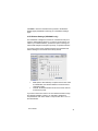
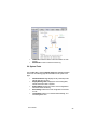
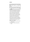
4.1 Network-to-Network
In a network-to-network VPN, the VPN joins the network on the LAN
side of the router with another network (which may be the LAN side
of another router). In between the two is a connection that may not
be trusted (the public Internet). The VPN allows traffic to “tunnel”
securely through the network cloud.
User’s Manual
41
LAN 1
VR2004 A
Internet
VR2004 B LAN 2
WAN IP: 172.16.0.123
Netmask: 255.255.255.0
LAN IP: 192.168.123.254
WAN IP: 10.10.0.123
Netmask: 255.255.255.0
LAN IP: 192.168.100.254
You will require three pieces of information about each LAN that is
taking part in a VPN connection:
1.
2.
3.
The remote Network IP address of the LAN. This will usually be
the same as the address of the LAN port of the router, with the
last segment of the address changed to ‘0’.
The remote IP Netmask. This is the subnet mask that describes
the network. Most users should leave this at the default value
of 255.255.255.0.
The remote gateway IP address. This is the WAN address of
the router that is connecting the remote network to the Internet.
If the remote router is acquiring a dynamic IP address from its
ISP, enter 0.0.0.0.
Note: In this case, the remote end of the tunnel will have to initiate the connection. It is not possible to form a VPN between
two networks whose gateways each receive a dynamic IP address.
Important! Each network joined by VPNs must have a different network address. This means that if you leave the LAN address of the
first router set to the default value of 192.168.123.254, you should
change the LAN address of any other router connecting to the first
to another value. A good way to do this would be to change the third
octet of the IP address to a different value1.
Your configurations for both ends of the tunnel described in the previous diagram should look like the following:
1. The LAN side of the VR2004 uses one of a set of IP addresses reserved for private addresses, as defined in RFC 1918. They are:
From
10.0.0.0
172.16.0.0
192.168.0.0
To
10.255.255.255
172.31.255.255
192.168.255.255
Most of the addresses shown in this manual are taken from these ranges. For more information about these addresses, see RFC 1918: ftp://ftp.isi.edu/in-notes/rfc1918.txt
42
FriendlyNET VPN Security Router
VR2004 ‘A’ (West end)
•
•
•
•
•
•
•
Connection Name: West-East
Local IPSec Identifier: West (Allows you to identify multiple tunnels and does not have to match the name used at
the other end of the tunnel. May be left blank. The default
value is Local.)
Remote IPSec Identifier: East (Allows you to identify multiple tunnels and does not have to match the name used at
the other end of the tunnel. Maybe left blank. The default
value is Remote.)
Remote IP Network: 192.168.100.254
Remote IP Netmask: 255.255.255.0
Remote Gateway IP: 10.0.0.123
Network Interface: WAN ETHERNET
VR2004 ‘B’ (East end)
•
•
•
Connection Name: East-West
Local IPSec Identifier: East
Remote IPSec Identifier: West
User’s Manual
43
•
•
•
•
Remote IP Network: 192.168.123.0
Remote IP Netmask: 255.255.255.0
Remote Gateway IP: 172.16.0.123
Network Interface: WAN ETHERNET
4.2 Client-to-Network
To connect a remote client PC to your network, use one of the following configurations based on the type of IP address of the client:
Mode 1— Dynamic IP Address
The remote PC obtains a dynamic IP address, and the user has to
setup the IPSec Client software (i.e. SSH). In this case, you must
configure the router with the following:
•
•
•
•
•
•
Remote IP Network: 0.0.0.0
Remote IP Netmask: 0.0.0.0
Remote Gateway IP: 0.0.0.0
Network Interface: The interface on the router used to
communicate with the remote network. Most users should
leave this set to WAN ETHERNET
Local IPSEC Identifier: Allows you to identify multiple tunnels and does not have to match the name used at the
other end of the tunnel. This field may remain blank. The
default value is Local.
Remote IPSEC Identifier: Allows you to identify multiple
tunnels and does not have to match the name used at the
other end of the tunnel. This field may remain blank. The
default value is Remote.
Note: If you need to use Manual Mode (as described in
section 4.4), you must enter valid addresses in all the
fields, as they cannot be 0.0.0.0.
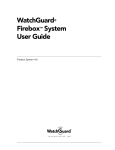
Mode 2—Static (fixed) IP Address
The remote PC obtains a fixed IP address, and the user must setup
the IPSec Client software (i.e. VPNCOM) that will act as a virtual
NIC card (the PC will appear to the router as a virtual NIC card). In
this case, you must configure the router with the following:
44
FriendlyNET VPN Security Router
Internet
PC A
WAN IP: 172.16.0.123
Netmask: 255.255.255.0
Virtual LAN IP: 192.168.123.0
VR2004
WAN IP: 10.10.0.123
Netmask: 255.255.255.0
LAN IP: 192.168.100.254
Mode 2
•
•
•
•
•
•
Remote IP Network: 192.168.123.0
Remote Netmask: 255.255.255.0
Remote Gateway IP: 172.16.0.123
Network Interface: The interface on the router used to
communicate with the remote network. Most users should
leave this set to WAN ETHERNET
Local IPSEC Identifier: Allows you to identify multiple tunnels and does not have to match the name used at the
other end of the tunnel. The default value is Local.
Remote IPSEC Identifier: Allows you to identify multiple
tunnels and does not have to match the name used at the
other end of the tunnel. The default value is Remote.
Note: If you do not know the Remote Gateway IP of the
remote client, you can enter 0.0.0.0. However, the VPN
connection request must then be initiated by the client. If
you select Manual Mode, you must enter the Remote
Gateway IP address.
4.3 IPSec Keying (IKE Mode)
A VPN tunnel is formed of two separate Secure Associations, or
SAs. One SA is used for traffic in each direction, and the router will
keep track of both SAs for you. Since the router is going to be encrypting the packets that are sent across an unsecured network (the
Internet), it needs a way to share a key so that each router can decrypt the data it receives.
User’s Manual
45
The preferred way to do this is with automatic keying using the
Internet Key Exchange Protocol (IKE). This requires that your ISP
or firewall allows traffic for TCP port 500. Check with your ISP or
network administrator if you are not sure if traffic for TCP port 500 is
allowed.
If IKE is impossible for some reason, you can set up the router’s
keys for each tunnel manually. This is described in more detail below (see section 4.4).
The other parameters on the VPN Settings page control how the
VPN tunnel is set up. If you are creating the Secure Association
(SA) using the IKE Mode (the default mode), complete the fields
described in the following sections.
4.3.1 Perfect Forward Secure
This is an optional feature of IKE. When enabled (the default setting), this feature may impose some additional overhead on the
router, but can offer added protection against an eavesdropper being able to decode the encrypted data. Either setting is acceptable,
but both ends of the tunnel must match settings. Click the respective radio button to enable or disable this feature.
4.3.2 Encryption Protocol
The router is able to use two encryption protocols: choose NULL
(no encryption), DES, or Triple DES (3DES). The same protocol
must be chosen (must match) that provided by the remote device.
Unless you have a need for one of the others, you should select
3DES.
46
FriendlyNET VPN Security Router
4.3.3 Pre-Shared Key
IKE can establish a key for the two ends of the tunnel to use to encrypt the traffic bound for the other network, but it cannot guarantee
that the router on the other end of the tunnel can be trusted. The
Pre-Shared key is used to establish that trust. Enter an alphanumeric name to be the Pre-Shared Key (max. length is 256 characters). The value must match the key name of the remote device.
4.3.4 Key Life
The Key Life value sets the amount of time until the router renegotiates the key, thereby decreasing the likelihood of a security breach.
The default is 3600 seconds (one hour).
4.3.5 IKE Life Time
This value sets the amount of time until the router renegotiates the
IKE security association. The default is 28800 seconds (8 hours).
4.4 Manual Mode
Important! Asanté recommends that only experienced users attempt to configure this advanced feature.
Many ISPs will not allow connection through their firewalls using the
IKE mode. In this case you must select the Manual Mode to create
the Secure Association.
User’s Manual
47
The following sections describe the parameters that will need to be
entered for a manually keyed tunnel.
4.4.1 Incoming and Outgoing SPI (Security Parameter
Index)
The SPI is a 32-bit field that the router will use to identify the Secure
Association. Enter a different 8 hexadecimal digit (such as
“12abcdef” or “01234567”) into each the Incoming SPI and Outgoing SPI fields.
The incoming SPI MUST match the outgoing SPI at the other end of
the tunnel. Similarly, the outgoing SPI value MUST match the incoming SPI at the other end of the tunnel.
4.4.2 Encryption Protocol
The router supports two encryption algorithms: DES and 3DES. Use
the drop down menu to select a protocol (Selecting NULL disables
encryption).
Note: The protocol chosen must match that used by the remote device.
4.4.3 Encryption Key
This string is used as a key to encrypt and decrypt the data transmitted. Use an alpha-numeric value of 24 characters for 3DES
(max. length for DES is 8 characters).
Note: The value entered must match that used by the remote device.
4.4.4 Authentication Protocol
The router supports two authentication algorithms, MD5 and SHA-1.
Use the drop down menu to select the desired protocol.
Note: The selected protocol must match that used by the remote
device.
48
FriendlyNET VPN Security Router
4.4.5 Authentication Key
This string is used as key authentication. Use an alpha-numeric
value of 16 characters (MD5) or 20 characters (SHA-1).
Note: The value entered must match that used by the remote device.
After configuring all the VPN values that are required, click on the
Save button. This accesses the Save & Restart page. Click the
Save & Restart button. Do not turn off the router while it is saving.
To further edit or delete a VPN tunnel, access the VPN Settings
page from the Setup Wizard. Uncheck the Enable box to disable an
individual VPN tunnel. Click the Edit (or Del) button to change the
VPN’s values.
User’s Manual
49
50
FriendlyNET VPN Security Router
Appendix A. Warranty Statement and
FriendlyCare Support
Subject to the limitations and exclusions below, Asanté warrants to the original end user purchaser that the covered products will be free from defects in
title, materials and manufacturing workmanship for a period of two years
from the date of purchase. This warranty excludes fans, power supplies,
non-integrated software and accessories. Asanté warrants that the fans and
power supplies will be free from defects in title, materials and manufacturing
workmanship for two years from date of purchase. Asanté warrants that nonintegrated software included with its products will be free from defects in
title, materials, and workmanship for a period of 90 days from date of purchase, and the Company will support such software for the purpose for
which it was intended for a period of 90 days from the date of purchase. This
warranty expressly excludes problems arising due to compatibility with other
vendors’ products, or future compatibility due to third party software or driver
updates.
To take advantage of this warranty, you must contact Asanté for a return
materials authorization (RMA) number. The RMA number must be clearly
written on the outside of the returned package. Product must be sent to Asanté postage paid. In the event of a defect, Asanté will repair or replace defective product or components with new, refurbished or equivalent product or
components as deemed appropriate by Asanté. The foregoing is your sole
remedy, and Asanté's only obligation, with respect to any defect or nonconformity. Asanté makes no warranty with respect to accessories (including
but not limited to cables, brackets and fasteners) included with the covered
product, nor to any discontinued product, i.e., product purchased more than
thirty days after Asanté has removed such product from its price list or discontinued shipments of such product.
This warranty is exclusive and is limited to the original end user purchaser
only. This warranty shall not apply to secondhand products or to products
that have been subjected to abuse, misuse, abnormal electrical or environmental conditions, or any condition other than what can be considered normal use.
ASANTÉ MAKES NO OTHER WARRANTIES, EXPRESS, IMPLIED OR
OTHERWISE, REGARDING THE ASANTÉ PRODUCTS, EXCEPT TO THE
EXTENT PROHIBITED BY APPLICABLE LAW, ALL WARRANTIES OR
CONDITIONS OF MERCHANTABILITY OR FITNESS FOR A PARTICULAR
PURPOSE ARE HEREBY DISCLAIMED. ASANTÉ'S LIABILITY ARISING
FROM OR RELATING TO THE PURCHASE, USE OR INABILITY TO USE
THE PRODUCTS IS LIMITED TO A REFUND OF THE PURCHASE PRICE
PAID. IN NO EVENT WILL ASANTÉ BE LIABLE FOR INDIRECT, SPECIAL,
INCIDENTAL, OR CONSEQUENTIAL DAMAGES FOR THE BREACH OF
ANY EXPRESS OR IMPLIED WARRANTY, INCLUDING ECONOMIC
User’s Manual
51
LOSS, DAMAGE TO PROPERTY AND, TO THE EXTENT PERMITTED BY
LAW, DAMAGES FOR PERSONAL INJURY, HOWEVER CAUSED AND
ON ANY THEORY OF LIABILITY (INCLUDING NEGLIGENCE). THESE
LIMITATIONS SHALL APPLY EVEN IF ASANTE HAS BEEN ADVISED OF
THE POSSIBILITY OF SUCH DAMAGES OR IF THIS WARRANTY IS
FOUND TO FAIL OF ITS ESSENTIAL PURPOSE.
Some jurisdictions do not allow the exclusion or limitation of incidental or
consequential damages or limitations on how long an implied warranty lasts,
so the above limitations or exclusions may not apply to you. This warranty
gives you specific legal rights, and you may have other rights, which vary
from jurisdiction to jurisdiction.
Asanté offers a FriendlyCare support program, a comprehensive
technical support plan to help you get the most from your
FriendlyNET products. (See Appendix B for information about registering your router.)
On-line Support
These resources are available 24/7 via www.asante.com/support:
•
•
•
Web (including forums, support guides, and white papers)
TechInfo Library (knowledgebase)
Downloads (manuals, drivers, and firmware)
Personalized Support
If you have a question about the use or configuration of an Asanté
product, complete the contact form at www.asante.com/support/
contact with a detailed description of your configuration. Most questions are answered the same day or 1– 2 business days.
Telephone support is available during business hours (Mountain
Standard Time) at 801-566-8991; check with your telephone company about toll charges.
Asanté Forums
With a simple registration process, you can join Asanté’s web support forums. Check out various topics and products and post your
own questions or answers related to our products.
52
FriendlyNET VPN Security Router
Appendix B. FCC Statement
This equipment has been tested and found to comply with the limits
for a Class B digital device, pursuant to part 15 of the FCC Rules.
These limits are designed to provide reasonable protection against
harmful interference in a residential installation. This equipment
generates, uses and can radiate radio frequency energy and, if not
installed and used in accordance with the instructions, may cause
harmful interference to radio communications. However, there is no
guarantee that interference will not occur in a particular installation.
If this equipment does cause harmful interference to radio or television reception, which can be determined by turning the equipment
off and on, the user is encouraged to try to correct the interference
by one or more of the following measures:
•
•
•
•
Reorient or relocate the receiving antenna
Increase the separation between the equipment and receiver
Connect the equipment into an outlet on a circuit different
from that to which the receiver is connected
Consult the dealer or an experienced radio/ V technician
for help
User’s Manual
53
54
FriendlyNET VPN Security Router
Appendix C. Troubleshooting
Before beginning the troubleshooting process, please check the
System Requirements found in Chapter 1 have been met. If not,
resolve the System Requirement deficiencies before attempting to
troubleshoot further.
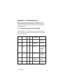
C.1 Troubleshooting with the Status LEDs
Consult Chapter 1.4 for information on the normal operation of the
LEDs. For brevity, this table only shows abnormal or unusual status
conveyed by the LEDs.
LEDs
Function
Color
Status
Link-Activity
Green
Off
No network connec- Check network
tion
cable connection
Wireless
Wireless
(VR2004AC Status
only)
Green
Off
No wireless connection OR no
traffic detected
Check network
cable connection.
COM
Dial-Up
Modem
Status
Green
Off
No analog modem
detected
Verify that the
router is configured
for dial-up Modem
(see Chapter
2.1.6). Check
network cable
connection
WAN
Link-Activity
Green
Off
No network connec- Check broadband
tion
modem, check
network cable
connection
Status
Router Status Amber
On
Power-on self-test
or router is being
configured
If LED stays on,
contact Technical
Support.
Power
Power
Off
No power to unit
Check power
adapter and source
1,2,3,4
User’s Manual
Green
Problem
Description
Suggestions
55
C.2 Problems Accessing Router
If you have problems accessing the router, please check the following:
1.
2.
3.
Can you ping 192.168.123.254? If so, disable the proxy in your
browser's setting.
If http://192.168.123.254 does not work, try
http://192.168.123.254:88.
If you are unable to ping the router, do the following:
a. Check the configuration of the computer. It must be on the
same subnet as the router (192.168.123.xxx). If not, refer to
Appendix D, or to the Quick Start Guide for information on how
to configure TCP/IP for your computers.
b. Check the Link LEDs of the computer’s network adapter
port and the corresponding router port to be sure they are on. If
not, check the Ethernet cable(s).
C.2.1 Using Windows Ping
To ping an IP address from Windows:
1.
2.
3.
From the Windows Start button, choose Run…
In the dialog box, type ping 192.168.123.254 and click OK.
You’ll see an MS-DOS dialog box showing the ping activity. If it
“times out” then there is no logical connection from your computer to the target device (router).
C.2.2 Using Macintosh WhatRoute
To ping the router from a Macintosh computer, perform the following
steps:
1.
2.
3.
4.
5.
56
Install the WhatRoute 1.7 program from the CD.
Double-click on the WhatRoute icon to launch the program.
In the main WhatRoute window, select Ping from the menu
Enter the address to ping in the Host: field.
Click ping to begin the test.
FriendlyNET VPN Security Router
C.3 Cabling Problems
Network cables connect devices in an Ethernet network, such as
computers, printers, hubs, routers and Cable/DSL modems. The
network connections provided by Ethernet cabling allow the devices
to share information, and allow a LAN to access the Internet.
Faulty Ethernet cables can cause problems in an otherwise healthy
network, creating periods of downtime which can be both frustrating and costly.
Follow the steps below if you suspect the problem is with your cabling:
1.
2.
3.
Make sure all cable is Category 5 (or CAT 5) or better. This
standard of cable is recommended for 10BaseT Ethernet networks, and is required for 100BaseTX networks.
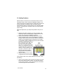
Make sure that all cables connecting devices such as computers and printers to the router are workstation (or “straight
through”) cables and are wired to IEEE T568A or T568B specifications. See the diagram below to determine if your cables
are workstation cables. (T568B wiring shown for demonstration
purposes). To determine if your cable is a straight through cable, hold
both ends of the cable together
away from you with the clip portion
down. Pin 1 should be on your left.
Verify that the wires of each clip are
identical. If they are different, you
may have a “crossover” cable”. Replace the cable with a straight
through cable and release and renew your client.
Release and Renew Client. Refer
to Appendix D for more information.
If the problem is with a hub or switch attached to the router, check
the following:
1.
Attach a known working client computer and cable to the router
port used to attach the hub or switch. This will verify that the
router port is functioning. If the router is defective, call Asanté
Technical Support for further assistance.
User’s Manual
57
2.
3.
If the port functions correctly, make sure the router is attached
to an Uplink Port on the hub or switch. If there is an Uplink
button on the hub or switch, make sure it is in the Uplink position.
If there is no uplink port on the hub or switch, then you will
need to purchase a crossover cable from your electronics
dealer.
Note: Most workstation cables purchased from computer or electronic stores will be wired to T568A or T568B specifications.
Other hints about cabling
The following are other ways to avoid problems with cabling:
1.
2.
3.
4.
5.
6.
Try to avoid running cables near or across power cables.
Staples should not be used to secure Ethernet cables. Clips or
hangers used for telephone wires are available at most hardware stores.
Avoid devices that create “noise”, such as florescent light fixtures, printers, copy machines, electric heaters, speakers, TV
sets, microwave ovens, telephones, electric fans, and washing
machines.
If you bundle a group of cables together with cable ties (zip
ties), do not tighten them so tightly that you deform the cables.
Avoid stretching Ethernet cables. This can cause them to become defective.
NEVER run Ethernet cable outside of a building. This can produce a very dangerous lightning hazard.
If after trying the above tips, you cannot solve your problem, contact
Asanté’s Technical Support. Before you do, however, please register your router online at www.asante.com/support/registration.html.
By doing so, you’ll be entitled to special offers, up-to-date information and important product bulletins.
58
FriendlyNET VPN Security Router
Appendix D. Renewing Client IP Addresses
Perform the following to renew the IP addresses of client computers
after configuring your VR2004 Series Router:
D.1 Windows 98/Me
Perform the following steps to Release and Renew the IP Address
on each client attached to the router:
1.
2.
3.
4.
5.
6.
7.
Go to the Start Button on the lower menu bar.
Select Programs/DOS Prompt from the menu.
At the DOS Prompt, type winipcfg and press Enter.
Select your adapter card from the list shown.
Click the Release All button.
Click the Renew All button.
Click OK.
D.2 Windows NT/2000
Perform the following steps to reset the IP address of any Windows
NT or 2000 computers:
1.
2.
3.
4.
5.
Go to the Start button on the lower menu bar. From the Start
button, choose Run.
Type Command and press Enter.
At the command line, type ipconfig/release_all and press Enter.
Type the command ipconfig /renew_all and press Enter.
Type Exit and press Enter to return to Windows.
The configuration of your Windows client is now complete.
D.3 Macintosh
It is not necessary to renew the IP address of any Macintosh client
configured for DHCP Server. The IP address is automatically renewed if needed when an Internet application is launched.
User’s Manual
59
60
FriendlyNET VPN Security Router
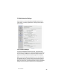
Appendix E. Service Ports
The table below lists some of the more common TCP and UDP service ports.
Port
Service
20
FTP-DATA
21
FTP
23
Telnet, Internet BBS
25
SMTP, Send mail
53
DNS
67
BOOTP bootstrap protocol
79
finger
80
HTTP, worldwide web
110
POP3, receive mail
113
Auth, authentication
119
NNTP, net news
161
SNMP, network management
162
SNMP-TRAP, network management
443
HTTPS, secure worldwide web
517
TALK
518
NTALK
1723
PPTP, Microsoft VPN (virtual private network)
2049
NFS, Sun Network File System
User’s Manual
61
62
FriendlyNET VPN Security Router
Appendix F. Hardware and Software
Compatibility
Protocols Supported
TCP/IP, NAT, DHCP, PPP, PPPoE, VPN
Network and Client Platforms compatibility
Windows 95/98/NT/2000/Workstation
Microsoft Windows NT Server
UNIX System (Linux, OpenBSD, SCO-UNIX)
Application Software Compatibility
Microsoft Internet Explorer
Netscape Navigator/Communicator
FTP related software
ICQ
NetMeeting V3.01
Microsoft Outlook
Microsoft Outlook Express
TCP/IP based Internet applications
User’s Manual
63
64
FriendlyNET VPN Security Router
Appendix G. Specifications
Connectors:
VR2004AC
Status Indicators:
Wireless (VR2004AC only) ports.
LAN: 4 Fast Ethernet (100BaseTX, 10BaseT): RJ-45
WAN: 1 Fast Ethernet (100BaseTX, 10BaseT): RJ-45
COM: Serial (analog modem or ISDN TA): DB9
WLAN: 11 Mbps (802.11b) at 18 dBm signal with
Power, Status, Link/Activity (per port), WAN, COM and
Software Overview
Administration:
Configure locally or remotely from a web browser (Internet
Explorer or Netscape, version 4 or later)
Device Information:
Router IP address, LAN MAC address, WAN MAC address and firmware version.
Device Status:
Graphical display of LAN, Cable/DSL Modem and Backup
Modem status. DHCP log with LAN IP and MAC address.
Setup Wizard:
Guide user through the initial configuration: time zone,
device IP, ISP settings (dynamic or static IP address),
PPPoE/PPTP (user name, password), Cable (host name,
domain name), Device MAC address, Wireless
(VR2004AC: SSID, channel, 64 or 128-bit WEP encryption), Modem (phone number, user name, password, IP,
baud rate, initialization strings) and VPN settings.
Virtual Private Network (VPN)
Connections:
Identifiers:
Remote Network IP:
Network Interface:
Secure Associations:
Server Interoperability:
Client Interoperability:
User’s Manual
Select up to 8 simultaneous connections (tunnels).
Local IPSec and remote IPSec.
Address, netmask and gateway.
WAN or COM ports.
Choose IKE or manual key.
For IKE, perfect forward secure, pre-shared key, key life
and IKE lifetime.
For manual, incoming SPI, outgoing SPI, NULL/
DES/3DES encryption protocols, encryption key, MD5/
SHA-1 authentication protocols and authentication key.
Cisco 2600 Series Routers, Nokia VPN CC500 Gateway,
Multitech RouteFinder RF650VPN, SonicWALL and
CheckPoint SecureVPN
Microsoft Windows 2000 Server, Nortel IPSec Client, Red
Hat Linux 7.0, Ashley Laurent VPCom Client, SSH Sentinel VPN Client and SafeNet
65
Advanced Settings
DHCP:
Virtual Server:
Static Routing:
Dynamic Routing:
LAN Filtering:
WAN Filtering:
Administration:
Dynamic DNS:
URL Filtering:
Email Alert:
System Tools
Intruder Detection:
Routing Table:
System Status:
Settings:
Upgrade Firmware:
Reset Device:
Security Features
Firewall:
66
Dynamic host configuration protocol automatically assigns
IP address to specified clients. Choose address pool range.
Reserve LAN IP addresses for selected devices (by MAC
addresses).
De-Militarized Zone (DMZ) for specific IP address. Forward
service port range to specific LAN IP address.
Destination IP address, subnet mask and gateway address.
Send (RIP 1, RIP 1/2) and receive (RIP 1, RIP 1/2).
Secure packet inspection (SPI) filters (block or pass) outbound LAN traffic based on specified protocols, IP address
range and destination service port ranges.
Secure packet inspection (SPI) filters (block or pass) inbound WAN traffic based on specified protocols, IP address
range and destination service port ranges.
Password, enable remote administration, remote admin
HTTP port, remote IP address and remote ping. Enable
system log, log server IP address and detail IPSec debug
log. Force PPPoE to reconnect. Force maximum transmission unit (MTU) size.
Dynamic DNS server, host name, user name and password.
Accepts wildcards.
Blocks access to targeted URLs
Sends system alerts and logs via email to email server and
destination email address. Schedule immediately, hourly,
daily (at specific time) or only when log is full.
Identifies suspicious activity and protects against 11 different types of denial of service (DoS) attacks, logs time, protocol, source IP address (and port), destination IP address
(and port) and describes event.
Displays type (INTF, RIP1), destination IP address, subnet
mask, gateway IP address and hop count.
Summarizes complete router configuration and status.
Saves or loads router settings from a file (or factory default).
Links to asante.com to check for latest firmware. Upgrade
firmware from a file.
Restarts router.
Hides local network addresses behind the router using Network address translation (NAT). Secure Packet Inspection
(SPI) evaluates both inbound (WAN) and outbound (LAN)
packets.
FriendlyNET VPN Security Router
Intrusion:
Access Control:
Business Controls:
Applications Interoperability
Microsoft:
Apple:
Messaging:
Others:
Tournament
Standards Compliance
Network:
VPN Encryption:
Triple DES (3DES)
Wireless Encryption:
Authentication:
secure hash algorithm (NIS94c)
Password:
and MSCHAP
Key Management:
ISAKMP, Oakley, and Skeme
Routing:
2 (RFC 1721)
Translation:
Transmission:
User’s Manual
Detects 11 types of denial of service (DOS) attacks including:
ping of death (illegal ping packet), SYN flood (detects if SYN
is from the same source), LAND attack (same source and
destination addresses), IP spoofing (simulates a LAN
packet), Code Red 1 (pattern I), Code Red II (pattern II), UDP
loopback (illegal UDP echo), smurf attack (ping with destination address as broadcast), snork attack (same source and
destination port), TCP null scan (SYN packets with sequence
= 0) and zero length IP option (illegal ICMP IP fragment).
Detects, logs and reports all suspicious activities.
Limits wireless LAN traffic only to registered computers with
specified hardware (MAC) address
Blocks access to certain websites (URL)
Universal Plug-and-Play (UPnP) and NetMeeting.
AppleTalk and QuickTime.
H.323, AOL Instant Messenger, ICQ and MIRC
RealPlayer, Dialpad, Quake, Half-Life and Star Craft Unreal
IEEE 802.3u Fast Ethernet over 2 pairs of UTP Category 5
(100BaseTX)
IEEE 802.3 Ethernet over 2 pairs of UTP Category 3
(10BaseT)
VR2004AC: IEEE 802.11b Wireless Ethernet over 2.4GHz
NULL, 56-bit Data Encryption Standard (DES) and 168-bit
VR2004AC: 64- and 128-bit Wired Equivalent Privacy (WEP)
IP Authentication Header (AH), MD5 (RFC 1321), SHA-1
Password authentication protocols PAP, CHAP (RFC 1334)
Internet Key Exchange (IKE, RFC2409) incorporating
IP Encapsulating Security Payload (ESP, RFC 1827)
Routing information protocols RIP 1 (RFC 1058), RIP Version
Network Address Translation (NAT, RFC 1631)
Point to Point Protocol over Ethernet (PPPoE, RFC 2516)
and Point to Point Tunneling Protocol (PPTP)
67
Performance
Processor:
Memory:
LAN:
WAN:
WLAN:
Physical Characteristics
Dimensions:
Weight:
Environmental Range
Operating Temperature:
Relative Humidity:
Power:
(100~240 VAC, 0.6 A)
Emissions:
Support
Product Warranty
Technical Support:
Product Updates:
68
32-bit RISC CPU
Upgradeable FLASH firmware from web browser
10/100 Mbps
10/100 Mbps
Up to 11 Mbps
7.9 x 5.9 x 1.7 inches (201 x 151 x 44 mm)
VR2004C: 1.0 pounds (0.45 Kg)
VR2004AC: 1.01 pounds (0.46 Kg)
32º to 104º F (0º to 40º C)
10% to 95% non-condensing
5 VDC, 2A. Includes external switching power module
FCC Class B and CE
Two-year product warranty covers defects in manufacturing
and workmanship.
90-days of free telephone support plus 24-hour support via
web.
Free download of maintenance releases from web
FriendlyNET VPN Security Router
Appendix H. Configuring a System Log Server
Because the router’s memory cannot hold as many messages as a computer
with a hard drive, you can have the router send its System Log messages to a
server on the network.
The ability to receive system log messages is most common on Unix-type systems. The following section describes how to set up a syslog server on Red Hat
Linux.
H.1 Red Hat Linux
All Linux distributions run a syslog daemon by default, but usually the daemon
won't listen for system log messages from the network. You will need root access to carry out the following steps:
1.
First we need to configure the syslog daemon to listen on the network:
Edit /etc/sysconfig/syslog and add the options -r -x to the line SYSLOGD_OPTIONS. Save the file.
# Options to syslogd
# -m 0 disables 'MARK' messages.
# -r enables logging from remote machines
# -x disables DNS lookups on messages received with -r
# See syslogd(8) for more details
SYSLOGD_OPTIONS=" -r -x -m 0"
2.
We also want to configure the system logger to use a specific file for messages from the router. We'll assume that the router has been configured to
use facility local5.
Edit /etc/syslog.conf and add a line for the router:
# Router is using local5
local5.*
/var/log/router.log
This says that all messages with facility local5 should be logged in /var/log/
router.log. (Note that the two portions of the line in syslog must be separated by tabs. Don't put any spaces between the two.)
3.
Now restart the syslog daemon:
User’s Manual
69
# /etc/init.d/syslog restart
4.
A default install of a recent version of Red Hat Linux has probably also configured a firewall that may be blocking access to
the syslog port. Usually ipchains is used by default. To add a
rule to the firewall for ipchains, edit the file /etc/sysconfig/
ipchains and add a rule allowing access to UDP port 514:
#Allow router to send syslog messages:
-A input -s 192.0.2.254/32 -d 0/0 514 -p udp -j ACCEPT
Note that we have allowed only the a single IP address (the
router’s IP address) to send syslog messages. This is a reasonable security measure since syslog messages from an unexpected source pose a risk of filling the log server's hard
drive.
5.
Now restart ipchains:
# /etc/init.d/ipchains restart
6.
Enter the IP address of the server in the router’s Administration
Settings page. You should now see messages begin to appear
in the selected router.log file.
H.2 Mac OS X
Mac OS X runs a syslog daemon by default, but by default the daemon doesn't listen for system log messages from the network.
You will need root access to carry out the following steps:
1.
First we will configure the syslog daemon to listen on the
network:
Edit the startup script /System/Library/StartupItems/
SystemLog/SystemLog:
[Note: The repeated 'SystemLog' is not a typo.]
-StartService ()
{
70
FriendlyNET VPN Security Router
ConsoleMessage "Starting system log"
if [ -f /etc/syslog.conf ]; then
if ! pid=$(GetPID syslog); then
rm -f /dev/log
syslogd
fi
else
echo "Warning: syslogd was not started"
fi
}
-2.
Add a parameter -u to the end of the line that starts the
daemon:
syslogd -u
3.
4.
Save the file.
We also want to configure the system logger to use a specific file for messages from the router. We'll assume that
the router has been configured to use facility local5.
Edit /etc/syslog.conf and add a line for the router:
# Router is using local5
local5.*
/var/log/router.log
This says that all messages with facility local5 should be
logged in /var/log/router.log. (Note that the two portions of
the line in syslog must be separated by tabs. Don't put any
spaces between the two.)
5.
Now restart the system logger:
root# /System/Library/StartupItems/SystemLog/SystemLog
restart
6.
7.
You should also be using a firewall to protect your server.
Open the Sharing Preference pane in System Preferences.
Click on the Firewall tab and click New... to add a new
rule.
User’s Manual
71
8.
Select Other under Port Name. Enter 514 and syslog in the Port
Number and Description fields, and click OK.
You should now see messages begin to appear in the selected router.log
file.
Note: The default firewall tool provided by Mac OS X doesn't provide a
way to limit access only to one IP address. You can download a third
party utility that will allow you to create more complicated rules (for example, sunShield, found at http://homepage.mac.com/opalliere/shield_us.
html).
H.3 Microsoft Windows
Shareware versions of system loggers are available for other operating
systems at most of the popular websites (e.g., www.tucows.com). One
system log daemon that Asanté recommends is the Kiwi Syslog Daemon
for Windows (http://www.kiwisyslog.com/info_syslog.htm). They have both
a freeware and a commercial version.
Install the software onto your Windows server and then enter the server’s
network IP address into the router’s Administration Settings page.
72
FriendlyNET VPN Security Router
Appendix I. Your 802.11b Wireless Network
Thank you for choosing Asanté for your wireless networking solutions. In order to make wireless networking as safe and easy as
possible, please consider the following information when setting
up and using your wireless network.
Optimum Performance
The quality of your wireless network performance depends on numerous
factors, including the distance from the access point, structural interference, and the placement and orientation of the wireless device(s). The
following lists tips for better wireless reception:
•
•
•
•
•
•
•
The best rule of thumb for good signal strength and quality is to
have line-of-sight from the Asanté wireless router or wireless
access point (WAP) to the wireless computers. This means the
user should be able to see the router from the location where
the wireless client is placed
Keep the wireless router in an open area away from any large
objects such as cubicles, walls, or other obstructions
Keep the wireless router away from any electro-magnetic emitting devices that can cause troublesome interference, such as
computers, electrical cables, televisions, cordless phones, microwave ovens, and neighboring 802.11b wireless LANs
Keep obstructions from the immediate vicinity of wireless antennas
Elevate the wireless router above desktop clutter and low- to
mid-level obstructions, such as furniture
Rotate the wireless router and computers until the best signal
strength is achieved
The number of walls, windows, doorways, and other building
structures will reduce the range of the wireless signal. Place the
wireless router in the path of least resistance through these
structures for the best signal quality to the wireless workstations
User’s Manual
73
•
•
The type of walls, windows, doorways or other building
structures will affect the range of the wireless signal. Structures such as metal framed houses, windows containing
UV protective film, and residences with multiple floors will
all affect the signal quality
Standing too close to a wireless antenna will affect its signal strength and quality
Security
To join a wireless network, a wireless product “listens” for beacon
messages, which are unencrypted and contain such network information as the network’s Service Set Identifier (SSID) and the IP address of the access point. This makes it easy for outside parties to
try to find your network, use your bandwidth, or intercept data sent
to and from your network.
Asanté’s wireless security features protect your network from outside parties. The following sections describe steps to take to prevent unauthorized access to your wireless network. Please refer to
your Asanté product’s documentation for more information.
Administrator’s Password
Change the default password of the wireless device as soon as
possible to prevent unauthorized access or changes to your configuration. Regularly change the password to make it more difficult
for a hacker to access your network.
SSID
Asanté’s wireless products come with a default SSID set by the factory (Asanté’s default SSID is default). The default SSID is not secure from hackers looking for your network. Change the default
SSID to a unique name, one that is unrelated to your company and
one that is not secret information (like another password). Also,
change the SSID regularly so that it is more difficult for a hacker to
access your network.
74
FriendlyNET VPN Security Router
MAC Address Control
Every network device has a unique hardware address known as a
media access control (MAC) address. Enabling MAC address control allows you to control LAN and WAN access for each client in
your network. Hackers will be denied access using outside devices.
WEP Encryption
Wired Equivalency Privacy (WEP) security protocol offers basic privacy protection, but should be used to make it more difficult for
hackers to intercept data or access your network. Use the following
tips to maximize the benefit of WEP encryption:
•
•
•
•
Use the highest level of encryption available
Use a shared key
Use multiple keys
Change the WEP key regularly
Enabling encryption can decrease your network performance overall, but is necessary for transmitting sensitive data over your network.
By following these recommendations, you can enjoy optimal performance of your wireless network while preventing unauthorized
access.
User’s Manual
75
Asanté Technologies, Inc.
821 Fox Lane
San Jose, CA 95131
FriendlyNET VR2004 Series VPN Security Router
User’s Manual
SALES
800-662-9686 Home/Office Solutions
800-303-9121 Enterprise Solutions
408-435-8388
TECHNICAL SUPPORT
801-566-8991 Worldwide
801-566-3787 FAX
www.asante.com
Copyright © 2003 Asanté Technologies, Inc. Asanté is a registered trademark of Asanté Technologies, Inc. FriendlyNET is a trademark of Asanté Technologies, Inc. All
other names or marks are trademarks or registered trademarks of their respective owners. All features and specifications are subject to change without prior notice.
06-00647-00 Rev. D 4/03