1
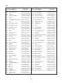
CMS254
COMPOUND MITRE SAW
©
0604
OPERATING & MAINTENANCE
INSTRUCTIONS
SPECIFICATIONS
Motor: ......................................................... 230V 50Hz 1 phase.
Current Rating ........................................... 6.5Amps
Power Rating: ............................................ 1300kW
No Load Speed: ........................................ 5000RPM
Fuse Rating ................................................ 13Amps
Dimensions: (Head Lowered) .................. 365x345x270mm
Dimensions: (Head Raised) ..................... 365x345x410mm
Blade size: (Fitted) .................................... 254mm 40T 16mm Bore
Noise level ................................................. 110dB at 1M
Vibration Level .......................................... 22.2m/s² (Normal Load)
Weight ........................................................ 10.7kg (unpacked)
Part Number .............................................. 6500785
Please note that the details and specifications contained herein, are correct at the time of going to
print. However, CLARKE International reserve the right to change specifications at any time without
prior notice. Always consult the machine’s data plate
Maximum Depth and Width of Cut
Type of Cut
Depth
Width
Cross (90°)
88mm
132mm
Mitre (at 45°)
88mm
100mm
Bevel (at 45°)
52mm
132mm
Compound (at 2x 45°)
50mm
100mm
Thank you for purchasing this CLARKE 254mm (10”) Compound Mitre Saw
which is designed for use by tradesmen in a light commercial environment.
Before operating the Mitre Saw please read this leaflet thoroughly and
carefully follow all instructions. This will ensure the safety of yourself and
that of others around you, and you can also look forward to the saw giving
you long and satisfactory service.
GUARANTEE
This CLARKE product is guaranteed against faulty manufacture for a period
of 12 months from the date of purchase. Please keep your receipt as
proof of purchase. This guarantee is invalid if the product is found to have
been abused or tampered with in any way, or not used for the purpose
for which it was intended.
Faulty goods should be returned to their place of purchase, no product
can be returned to us without prior permission.
This guarantee does not effect your statutory rights.
CONTENTS
CONT Specifications ...................................................................................... 2
Safety Precautions .............................................................................. 4
Additional Precautions for Mitre Saws .............................................. 6
Electrical Connections ....................................................................... 7
Principle Parts ...................................................................................... 8
Features ............................................................................................... 9
Assembly .............................................................................................. 10
Operation ............................................................................................ 11
Cross Cutting ....................................................................................... 11
Mitre Cutting ........................................................................................ 12
Bevel Cutting ....................................................................................... 13
Compound Mitre Cutting .................................................................. 13
Maintenance ...................................................................................... 14
Blade renewal ..................................................................................... 14
Adjustments ......................................................................................... 16
Maximum Cutting Sizes ...................................................................... 18
Parts and Service ................................................................................ 19
Parts Diagram ...................................................................................... 20
Parts List ................................................................................................ 21
3
SAFETY PRECAUTIONS
GENERAL SAFETY RULES FOR OPERATING MACHINERY
WARNING:
As with all machinery, there are certain hazards involved with their
operation and use. Exercising respect and caution will considerably
lessen the risk of personal injury.
However, if normal safety precautions are overlooked or ignored,
personal injury to the operator or damage to property, may result.
1. READ and BECOME FAMILIAR with the entire operating manual.
Learn the machines’ applications and limitations as well as the
specific potential hazards peculiar to it.
2. EARTH ALL MACHINES. If the machine is equipped with three-pin
plug it should be plugged into a three-pin electrical socket. Never
remove the earth pin.
3. ALWAYS ensure that ADEQUATE LIGHTING is available. A minimum
intensity of 300 lux should be provided. Ensure that lighting is placed
so that you will not be working in your own shadow.
4. CHECK for DAMAGE. Before using the machine, any damaged part,
such as a guard etc., should be checked to ensure that it will
operate properly, and perform its intended function. Check for
alignment of moving parts, breakage of parts, mountings, and any
other condition that may affect the machines’ operation. Any
damage should be properly repaired or the part replaced. If in
doubt, DO NOT USE the machine. Consult your local dealer.
5. DISCONNECT the MACHINE from the power supply before servicing
and when changing accessories such as blades, etc.
6. KEEP GUARDS in place and in working order.
7. ALWAYS WEAR SAFETY GOGGLES, manufactured to the latest
European Safety Standards. Also use a face or dust mask if the
cutting operation is dusty. Everyday eyeglasses do not have impact
resistant lenses, they are NOT safety glasses.
8. KEEP WORK AREA CLEAN. Cluttered areas and benches invite
accidents.
9. ALWAYS WEAR EAR PROTECTORS/DEFENDERS.
10. DON’T FORCE the Machine. It will do a better and safer job at the
rate for which it was designed.
4
11. REMOVE ADJUSTING KEYS AND WRENCHES. Form the habit of
checking to see that keys and adjusting wrenches are removed
from the machine before switching on.
12. DRUGS, ALCOHOL, MEDICATION. Do not operate machine while
under the influence of drugs, alcohol or any medication.
13. USE RECOMMENDED ACCESSORIES. The use of improper accessories
could be hazardous.
14. NEVER LEAVE MACHINE RUNNING UNATTENDED. Turn power OFF. Do
not leave machine until it comes to a complete stop.
15. ALWAYS REMOVE PLUG from electrical outlet when adjusting,
changing parts, or working on machine.
16. AVOID DANGEROUS ENVIRONMENT. Don’t use power machines in
damp or wet locations or expose them to rain. Keep your work area
well illuminated. DO NOT USE in explosive atmosphere (around
paint, flammable liquids etc.).
17. KEEP CHILDREN AWAY. All visitors should be kept a safe distance from
the work area, especially whilst operating the unit.
19. MAINTAIN MACHINE IN TOP CONDITION. Keep tools sharp and clean
for the best and safest performance. Follow maintenance instructions.
21. DON’T OVERREACH. Keep your proper footing and balance at all
times. For best footing, wear rubber soled footwear. Keep floor clear
of oil, scrap wood, etc.
22. WEAR PROPER APPAREL. Loose clothing or jewelry may get caught in
moving parts. Wear protective hair covering to contain long hair.
23. MAKE WORKSHOP CHILDPROOF. Cover the saw adequately when
not in use, to prevent children from damaging themselves by
tampering with it.
24. NEVER STAND ON THE MACHINE. Serious injury could occur if the
machine is tipped or if a cutting tool is accidentally contacted. Do
not store materials above or near a machine, such that it is
necessary to stand on the machine to reach them.
25. HANDLE WITH EXTREME CARE Whenever transporting or installing
machinery, and always use a lifting tool.
26. AVOID ACCIDENTAL STARTING. Ensure the switch is OFF before
plugging in to mains.
27. BE AWARE that accidents are caused by carelessness due to
familiarity.
ALWAYS concentrate on the job in hand, no matter how trivial it may
seem.
52
ADDITIONAL PRECAUTIONS FOR MITRE SAWS
1. Wear safety goggles as protection against flying wood chips and saw
dust. In many cases, a full face shield is even better protection.
A dust mask is also recommended to keep saw dust out of your lungs.
2. Use a solid wood workbench which will not move under load.
3. This saw is for use by tradesmen in a light commercial environment.
4. Clear the work table of all objects except the workpiece (tools, scraps,
rulers etc.) before switching on the saw.
5. Keep your fingers well away from the blade.
6. Switch off the saw, and make sure the blade has come to a complete
stop before clearing sawdust or off-cuts from the table.
7. Make sure there are no nails or foreign objects in the part of the workpiece
to be sawn.
8. Set up the machine and make all adjustments with the power OFF, and
disconnected from the supply.
9. DO NOT operate the machine with the guards removed. They must all
be in place and securely fastened when performing any operation
10. Use ONLY approved replacement saw blades. Contact your local
CLARKE dealer for advice. The use of inferior blades may increase the
risk of injury.
11. DO NOT saw any material that does not have a flat surface on which to
bear.
12. Do Not force the blade, lower it gently into the work.
13. Ensure you have complete control of the Cutting Head at all times. When
a cut is completed, return it to its uppermost position gently.
DO NOT allow it to snap back heavily under spring pressure.
14. Always clamp the work to the table...DO NOT perform freehand
operations.
15. Ensure that the portion of the workpiece being cut bears firmly against
the back fence.
16. Provide adequate support for long workpieces.
17. Never use solvents for cleaning plastic parts as this could causedamage
to the material. A soft damp cloth only is required.
62
ELECTRICAL CONNECTIONS
Connect the mains lead to a standard, 230 Volt (50Hz) electrical supply
through an approved 13 amp BS 1363 plug, or a suitably fused isolator
switch.
WARNING! THIS APPLIANCE MUST BE EARTHED
IMPORTANT: The wires in the mains lead are coloured in accordance
with the following code:
Green & Yellow
-
Earth
Blue
-
Neutral
Brown
-
Live
As the colours of the flexible lead of this appliance may not correspond
with the coloured markings identifying terminals in your plug proceed as
follows:
•
Connect the GREEN & YELLOW cord to terminal marked with a letter
“E” or Earth symbol “ ” or coloured GREEN or GREEN & YELLOW.
•
Connect BROWN cord to terminal marked with “L” or coloured RED.
•
Connect BLUE cord to the terminal marked with “N” or coloured BLACK.
If this appliance is fitted with a plug which is moulded onto the electric
cable (i.e. non-rewirable) please note:
1. The plug must be thrown away if it is cut from the electric cable. There is a
danger of electric shock if it is subsequently inserted into a socket outlet.
2. Never use the plug without the fuse cover fitted.
3. Should you wish to replace a detachable fuse carrier, ensure that the
correct replacement is used (as indicated by marking or colour code).
4. Replacement fuse covers can be obtained from your local dealer
or most electrical stockists.
Fuse Rating
The fuse in the plug must be replaced with one of the same rating - 13amps
and this replacement must be ASTA approved to BS1362.
Cable Extension
If a cable extension is needed, it is essential to ensure that the size of the
conductors is at least the same size as those of the power cable supplied.
72
PRINCIPAL PARTS OF THE SAW
Fig 1
82
FEATURES
As its’ name implies, the machine is a Bevel/Mitre Saw, capable of straight
cross cutting, and cutting bevels and mitres, or a combination of the two.
The main arm, or Cutting
Fig 2
Head, carries the motor and
the tungsten carbide saw
blade. It is allowed to swivel
to produce mitre cuts and tilt
to the left to produce bevel
cuts.
The maximum sizes of wood
that may be cut in any of
these processes is given on
page 17.
A dust extraction port is
provided at the rear of the
machine to which the dust
bag (provided), is attached.
If required, a vacuum
extraction device may be
used which will provide fast
and efficient removal of
sawdust. The extraction device may be used continuously or intermittently
depending upon your requirements.
The Cutting Head is locked in
its lower position for transit
purposes. To release it, pull
out the Head Locking Pin,
(see also G, fig. 16, p16). It
may be necessary to apply
slight downward pressure to
the head in order to do so,
and allow the head to rise to
its upper position gently,
under control.
Fig.3
The head will lock in its upper
position, and is prevented
from being lowered until the
Head Release Lever (see fig.1
page 8) is moved sideways.
9
ASSEMBLY and INSTALLATION
On receipt inspect the machine to ensure that all parts are accounted for
and that no damage was incurred during transit. Any deficiency or
damage should be reported to your CLARKE dealer immediately.
The main body of the saw is fully assembled and adjusted at the factory.
It is necessary only to fit the accessories supplied, shown below.
Fig.4
Accessories provided with the machine
Mount the machine on a firm solid base that will not move under load.
Ensure there is an appropriate electrical supply, and adequate lighting,
so that you will not be working in your own shadow.
Four holes are provided in the base, shown at A fig. 3, so that the machine
may be bolted permanently to a workbench for added stability.
Alternatively it may be bolted to a piece of plywood with a thickness of 5/
8” minimum. If this method is preferred, the plywood support should be
clamped to a solid base or workbench whenever the saw is being used.
Fig.5
The Work Stop may be slipped
on to one arm of the right hand
work support before as shown in
fig. 5. The wing nut secures the
stop at any desired position, or
the stop may be swiveled out of
the way when not required.
Attach the Work Supports, one
to each side of the bed using the
Work Support Clamps.
10
Enter the screw with washer
down though the hole in the
bed (See Fig.5, and B, Fig.3),
and screw on the clamp from
below by a few turns, open
channel upwards.
Slide the work support into place
between the underside of the
bed and the clamp and tighten
the screw. Take care not to slide
the work support too far. The
position is correct when the
upturned ends of the support
are directly in line with the table surface.
Fig. 6
Attach the dust bag to the dust extraction outlet with its spring clip.
If required, the work clamp, shown in fig. 6 is mounted in holes ‘B’ fig. 3.
OPERATON
A. Cross Cutting. (at 90°) Ref: Fig. 7
First, set the work in place. Clamp it firmly against the table and back
fence. Check the security of the Bevel Lock shown at C, Fig 16, page 16,
and tighten the handle if necessary, also ensure the table is locked using
the table locking handle.
NOTE: If the workpiece is not entirely straight, ensure that the portion at
either side of the intended cut rests firmly against the table and back
fence.
Fig. 7
It is important to ensure that one
end of the workpiece is
completely free to move i.e. NOT
clamped or held in any way. This
will normally be the off-cut or
shorter end.
When satisfied, make a final
check to ensure that all safety
precautions are being complied
with, then pull and hold the
Trigger Release - A, whilst pulling
the Trigger - B, to start the motor.
11
Allow the blade to reach full speed. If any unusual sounds or vibrations
occur, release the Trigger immediately and investigate the cause.
When satisfied, move the Head Release Lever, (C fig.7 and also shown in
fig.10), sideways with the fingers of your right hand, and gently lower the
head so that the blade comes into contact with the workpiece. Do not
force the blade, a light pressure is all that is required.
You will notice that to provide maximum safety, the blade is not exposed
at any time, and the guard rises automatically as the blade is lowered.
Nevertheless, NEVER treat the machine with indifference, and NEVER be
casual with your approach.
To switch off, release the Trigger whilst still maintaining full control of the
head.
NOTE: The Head should rise under spring pressure, gently. If the movement
is too rapid or conversely, too sluggish, spring tension needs to be adjusted.
Refer to ‘Adjustments on page 16.
Fig. 8
B. Mitre Cutting
This is a cross cutting operation,
except that the saw blade is set
at an angle to the work, but
remains perpendicular to the
table. The head is mounted on
the table which is free to rotate
by up to 45°, left and right.
To set the required mitre angle
unscrew the Table Lock Handle
and rotate the Table, with the
Head and saw blade, to the
desired position, lining up the
angle on the scale, with the
pointer shown in Fig. 3 on page
9. Lock the Table in position with
the Locking Handle.
The procedure for cutting is the
same as that for cross cutting.
For convenience, positive stops are provided at various angles. These are:
Zero (90°), 22.5° and 45°
12
C. Straight Bevel
Cutting
Fig. 9
As with Mitre Cutting, this is a
cross cutting operation,
except that the blade is not
perpendicular to the table,
(see fig. 10).
Ensure the Table is set so that
the table pointer lines up with
the zero on the scale on the
bed.
Slacken off the Bevel Locking
Handle (C, fig.16), and swing
the Head to the side.
Fig. 10
Set the head to the required
angle according to the scale,
adjacent to the pivot point
and shown in fig 9.
Lock the head in position by
tightening the Bevel Locking
Handle.
The 45° adjuster is factory set
so that when the Head is tilted
to its fullest exent the blade
will cut a 45° bevel.
The procedure for cutting is
the same as that for cross
cutting.
D. Compound Mitre
and Bevel Cutting.
Fig. 11
Having determined the
angles you require, first set the
Bevel angle, using the
procedure described above,
and then the Mitre angle.
The procedure for cutting is
the same as that for cross
cutting.
13
MAINTENANCE
1. General
The machine is maintenance free, except for changing the saw blade when
necessary, maintaining adjustments, and ensuring that after use,
you clean away any sawdust or wood chips, with a low pressure air line or brush,
paying particular attention to the motor air vents which should be kept clear at all
times.
Should the motor not function normally, it is possible that it has become clogged
with saw dust, in which case, it will be necessary to disassemble the motor in order
to clean the various components. Contact your CLARKE dealer for advice.
2. Changing the Saw Blade
IMPORTANT: Exercise extreme care when handling the saw blade. The tips are
extremely sharp, and careless handling could result in severe personal injury.
1. With the Machine disconnected from
the mains supply, and the Cutting
Head in the raised position, remove
the lower screw and loosen the
upper screw securing the Blade Hub
Cover and Lower Blade Guard,
shown in Fig.12.
Fig. 12
This wil free the hub cover and Lower
Blade Guard. Leave the linkage
connected and rotate the lower blade
guard towards the rear of the machine,
out of harms way.
2. Lower the Head Assembly
and lock in place using the
Locking Pin.
Fig. 13
3. Remove the blade securing
screw, using the 1/2”AF
spanner (provided), whilst
holding the motor shaft
steady with a 3/16” Hex.
wrench, (also provided), as
shown in Fig. 13,
remembering that the bolt
has a LEFT HAND THREAD.
i.e. turn it CLOCKWISE to undo.
14
4. Remove the outer flange followed by the blade.
5. Replace in reverse order, ensuring the tips of the blade point downwards
at the front.
3. Renewing Motor Brushes
Fig. 14
Eventually, the motors’ carbon
brushes will need replacing. This
task may be carried out quickly and
easily as follows.
1. Remove the three cross head
screws,securing the motors’
end cover, andpull off the
cover.
2. With a pair of long nose pliers,
pull out each brush holder, as
shown in fig. 14, and disconnect
the push-on connector.
3. Insert the new brush with spring
into the holder, and reassemble
in reverse order, ensuring that each brush
holder is gently pushed into its housing with
the shoulder inwards (see fig. 15)
4. It is important to ensure that the brush holders
are fully home in their housings, and the pushon connections are secure before replacing
the end cover.
15
Fig. 15
ADJUSTMENTS Ref: Fig 16
It may be necessary from time to time, to check various settings and make
appropriate adjustments.
Fig. 16
a. Squareness of Blade
It is first of all most important to check that the blade is exactly
perpendicular to the table.
To do this, place a small square on the table and bring it up to the blade,
checking to see if it is square. If an adjustment is required, firstly slacken
the Bevel Locking Handle C, then slacken off the adjuster locknut at A,
screw the adjuster in or out, as the case may be until the blade is exactly
square, keeping light pressure on the head to keep it in contact with the
adjuster screw. When completely satisfied, lock the adjuster with the lock
nut, and with the head resting against the stop, tighten the Bevel Locking
Handle C.
NOTE: It simplifies matters if assistance is used during this process.
Check the position of the pointer in relation to the scale. If necessary zero
the pointer by slackening off the pointer securing screw, moving the pointer
accordingly and retighten the securing screw.
16
b. Squareness of Backfence
Place a square flat on the table with its base resting on the Backfence.
If it is not square with the edge of the slot in the table, slacken off the two
backfence securing screws D, sufficient to be able to move the fence
until it is square.
When satisfied, tighten the securing screws.
c. 45° Bevel Stop
Slacken off the Bevel lock (C), and tilt the Head to its maximum.
Lower the Blade and with a small 45° gauge between the bed and blade,
check for trueness of angle.
If an adjustment is required, slacken the adjuster locknut shown at B. and
screw the adjuster in or out as the case may be to acquire the correct
angle, and when satisfied, lock the adjuster with the locknut.
d. Cutting Head Spring Tension
To increase or decrease Cutting Head spring tension, slacken off the locking
screw at adjuster (E) and screw the adjuster in to increase or out to
decrease tension, and tighten the locknut when completed.
PARTS AND SERVICE CONTACTS
For Spare Parts and Service, please contact your nearest dealer,
or CLARKE International, on one of the following numbers.
PARTS & SERVICE TEL: 020 8988 7400
PARTS & SERVICE FAX: 020 8558 3622
or e-mail as follows:
PARTS: [email protected]
SERVICE: [email protected]
17
PARTS DIAGRAM
18
PARTS LIST
No. Description
1
Part No.
No. Description
Flat Hd Screw
DQ410101006
35
2
Stop
DQ0351310201
36
Pad
DQ0301020219
3
Upper Guard
DQ0351320101
37
Table Locking Handle
DQ0301020214
4
M16 Lock Nut
DQ410151010
38
Pad
DQ0351310302
5
Flat Washer
DQ412011039
39
Rivet
DQ410503001
6
Lock Pin
DQ0351310601
40
Scale
DQ0352415001
7
O-ring
DQ441010006
41
M10 Lock Nut
DQ411071004
8
Pointer
DQ0352410301
42
Spring
DQ0351310902
9
Pan Hd Screw
DQ410131005
43
Steel Ball
DQ420150004
10
Hex Nut
DQ411011004
44
Hex Hd Screw
DQ410011006
11
Hex Hd Screw
DQ4110011016
45
Lock Washer
DQ412021004
12
M6 Hex Nut
DQ411011004
46
Flat Washer
D412011008
13
Hex Hd Screw
DQ4110011016
47
Back Fence
DQ0352410103
14
Pivot
DQ0351310606
48
Base
DQ0351310104
15
Bracket
DQ0351310310
49
Pan Hd Screw
DQ410131005
17
D6 Flat Washer
DQ412011036
50
Pointer
DQ0351310303
18
D6 Lock Washer
DQ412021003
51
Pivot Bolt
DQ0351310603
19
Hex Soc Hd Screw
DQ410151010
52
Flat Washer
DQ412011023
20
Hex Hd Screw
DQ410011010
53
Wave Washer
DQ412010001
21
M6 Hex Nut
DQ411011004
54
Flat Washer
DQ4120110023
22
Dust Bag
DQ0301025002
55
M10 Lock Nut
DQ411071004
23
Set Screw
DQ410071009
56
Pan Hd Screw
DQ410251001
24
Set Screw
DQ410071005
57
Cover
DQ0301020204
25
Spring
DQ0351310901
58
0Needle Bearing
DQ420110001
26
Pipe
DQ0301030203
59
Jack Shaft Assy
DQ301020501
27
Bevel Turnnion
DQ0352410101
60
Retaining Plate
DQ0301010305
28
Bevel Lock
DQ0352410202
61
Pan Hd Screw
DQ410251009
29
Lock Washer
DQ412021002
62
Flange
DQ0602200901
30
Flat Washer
DQ412011038
63
Blade
DQ422020002
31
Pivot Bolt
DQ0352410102
64
Flange
DQ0602200901
32
Flat Washer
DQ412011011
65
Blade Securing Screw DQ0301010805
33
Pan Hd Screw
DQ410131020
66
M5 Lock Nut
DQ411071003
34
Table Insert
DQ0352410201
67
Hub Cover
DQ0351310306
19
Table
Part No.
DQ0352410104
cont.
No. Description
68
Part No.
No. Description
Part No.
Pan Hd Screw
DQ410131020
101 Power Cord
69
Spring
DQ0301030902
102 Terminal Block
DQ451050002
70
Lower Guard
DQ0351310202
103 Pan Hd Screw
DQ410251001
71
Plate
DQ0301030310
104 Ext Tooth Washer
DQ412041002
72
Carriage Hd Screw
DQ410031001
106 Hex Wrench
DQ0301020316
73
Link
DQ0351310307
107 Blade Wrench
DQ0301010313
74
Shoulder Screw
DQ0301020803
108 Capacitor
DQ0351321201
75
Shoulder Screw
DQ0301030801
109 Coil
DQ0351311202
76
Pan Hd Screw
DQ410191002
110 Cord Guard
DQ0602200206
77
End Cover
DQ0301020202
111 Flat Washer
DQ412011006
78
Pad
DQ0101070201
112 Shoulder Screw
DQ0301010809
79
M5 Hex Nut
DQ411011001
113 Spring
DQ0351310905
80
Pan Hd Screw
DQ410271002
114 Head Release Lever
DQ0351320301
81
Clamp
DQ0301020208
115 M5 Lock Nut
DQ411071003
82
Pan Hd Scr
DQ410191002
116 Bracket
DQ0351310317
83
Field
DQA351310443
117 Ext Tooth Washer
DQ412041001
84
Hex Hd Screw
DQ410291001
118 Pan Hd Screw
DQ410131020
85
Baffle
DQ0301020203
119 Stop
DQ0351310801
86
Armature Assy
DQA301020302
120 Box Spanner
See Dealer
87
Ball Bearing
DQ420010501
201 Pan Hd Screw
DQ410131024
88
Rubber Pin
DQ414060003
202 Flat Washer
DQ412011037
89
Handle
DQ0351320201
203 Work Support
DQ0351310311
90
Pan Hd Scr
DQ410191005
204 Work Stop
DQ0351310314
91
Brush Holder
DQ0101010502
205 Wing Screw
DQ410221001
92
Brush
DQ0101015005
206 Work Supp’t Clamp
DQ0351310313
93
Motor Housing
DQ0351320202
220 Screw Assy
DQA301023801
94
Spring
DQ0351310903
221 Pan Hd Screw
DQ410131011
95
Trigger Release
DQ0351320203
222 Fixed Plate
DQ0301020321
96
Switch
DQ452060001
223 Support
DQ0301020907
97
Spring
DQ0351310904
224 Clamp Plate
DQ0301020322
98
Trigger
DQ0351310208
225 Flat Washer
DQ412011015
99
Rubber Pin
DQ414060003
226 Pan Hd Screw
DQ410131020
100 Ball Bearing
DQ420010502
20
DQ0351320701
23