1
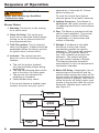
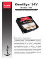
GeniSys 24V
™
PARTS & ACCESSORIES
Model 7559
Advanced 24 Vdc Burner Control
Description / Applications
The Beckett GeniSysTM 24V Advanced Burner Control is a
24 Vdc primary safety control for oil burners used in special
applications including, but not limited to, water heaters,
pressure washers, crack sealers and portable heaters having
firing rates less than 5.5 GPH. The GeniSysTM 24V is used
with a suitable cad cell flame sensor to control the oil burner
motor, igniter, and optional solenoid valve. It has 24 volt enable
input compatible with mechanical and high limit switches. It
can provide interrupted or intermittent duty ignition, and it has
a 15 second lockout time on flame failure.
Features
• Welded Relay Protection
• Limited Relight
• Valve-On Delay / Motor-Off Delay (Field
programmable with Beckett’s Contractor Tool)
• 15 Second Lockout Time
• Interrupted Ignition
• Communication Port
• Lockout Alarm Output
• Fused Protection
Specifications
Not Use This Control
CAUTION Do
in an Application that
Maintain Specified
WARNING Voltage
A low or erratic power supply could
result in impaired burner operation,
severe delayed ignition or an explosion
inside the heat exchanger resulting in a
burn and/or asphyxiation hazard.
y
y
y
is Not Within the Ratings Listed in This
Section. Improper Control Operation May
Result.
Not Use This Control
CAUTION Do
Above 5.5 GPH
y
Electrical Ratings
Inputs:
• Voltage: 24 Vdc nominal (21.6 to 30 Vdc)
• Current: 220 mA nominal (230 mA max at 30 Vdc)*
• Enable Load: 22mA at 24 Vdc
Outputs:
• Motor: 24 Vdc, 10 full load amps (FLA), 50 locked rotor
amps (LRA)
• Igniter: 24 Vdc, 3 A
• Solenoid Valve: 24 Vdc, 1 A
• Lockout Alarm: 24 Vdc, 1A
*
The 7559 control draws
40-55mA in the standby
state. If the red control wire is left powered
without a battery charging system, it can
drain a standard 45 Amp hour automotive
battery in four to six weeks.
NOTICE
y
Beckett DC Burners require a
continuous supply of 21.6 to 30 volts
DC (at 11 amps for Model ADC or 15
amps for Model SDC), measured at
the burner during operation.
Consult other DC burner
manufacturers’ specifications for the
correct voltage range.
Special Note: The 7559 Control
shuts the burner down if the input
voltage drops to a sustained level
of 20 volts DC, or below. Operation
resumes at a sustained input
voltage of 21 volts DC, or above.
An automotive or small engine
charging system that is capable of
supplying the required continuous
voltage/amperage is recommended
with certain road equipment, such
as asphalt hot patchers and similar
applications.
This is especially true while
maintaining nominal load temperatures
during idle periods.
Table 1 - Model Guide
Motoroff
delay
time1
Beckett
GeniSys
24V Control
Part No.
Lockout
Time
7559A 0000 1
15 sec
0 sec
0 sec
7559P 1530 1
15 sec
15 sec
30 sec
7559P 152M 1
15 sec
15 sec
2 min
7559P 158M
15 sec
15 sec
8 min
1
Valve-on
delay
time1
1 Valve-on delay and motor-off delay timings on all models are
Environmental Ratings:
•
•
2
Storage and Operating Ambient Temperature:
-40°F to +160°F (-40°C to +71°C)
Moisture: 5 to 95% RH, condensing
programmable with the Beckett Contractor Tool. Other factory
set timings are available. Contact Beckett for alternate
timings.
Installation/Operation/Maintenance
Explosion, Fire,
WARNING Professional
Service Required.
Incorrect installation or misuse of this
control could result in severe personal
injury or death from heavy smoke,
explosion or fire.
Please read and understand the manual
supplied with this control. This control
must be installed, adjusted and put into
operation only by a qualified individual or
service agency that is:
y Licensed or certified to install and
provide technical service to oil
heating systems.
y Experienced with all applicable
codes, standards and ordinances.
y Responsible for the correct
installation and commission of this
equipment.
y Skilled in the adjustment of oil
burners using combustion test
instruments.
The installation must strictly comply with
all applicable codes, authorities having
jurisdiction and the latest revision of
the National Fire Protection Association
Standard for the Installation of Oil-Burning
Equipment, NFPA 31 (or CSA-B139 and
CSA-B140 in Canada) for stationary
equipment.
Regulation by these authorities take
precedence over the general instructions
provided in this installation manual.
Electrical Shock
WARNING Hazard
Electrical shock can cause
personal injury or death.
y
y
y
severe
Disconnect ALL electrical power to
the equipment/burner circuit before
installing or servicing this control.
Provide ground wiring to the
equipment, burner and metal control
mounting box.
Perform all wiring in compliance with
the National Electrical Code ANSI/
NFPA 70 (Canada CSA C22.1).
WARNING Scald, & Burn Hazard
All heating equipment must
have HIGH LIMIT controls to
protect against excessive
temperature and/or pressure.
The control must interrupt electrical
power and shutdown the burner, if
operating or safety controls fail and
cause a runaway condition.
y
y
y
y
y
Follow the equipment manufacturer’s
wiring diagrams and note all required
safety controls.
Typical safety controls include high
temperature or pressure limits, low
water cutoffs, pressure relief valves
and blocked flue sensing switches.
Verify all limit and safety controls are
installed and functioning correctly,
as specified by the manufacturer,
applicable safety standards, codes
and all authorities having jurisdiction.
Insure that the equipment is free of
oil and oil vapor before starting or
resetting the burner.
Do not wire power directly to the
burner motor. Only wire the motor
as shown in Figure 2. If instant
burner heat is required by the
application, purchase or program a
control with a long motor-off delay
time, which will ensure instant heat
if a new call for heat is received
within the motor-off delay time.
■ Mounting:
○ Mount the control on a 4” x 4” junction box on the burner, or inside the
equipment cabinet. In replacement
applications, mount the new control in
the same location as the old control.
In some replacement applications, it
may be necessary to rotate the control on the 4” x 4” box for best fit.
○ Mounting orientation: any orientation
is acceptable with the exception of
up-side down.
GeniSys Control 24V Control Installation and Operation Manual
3
Figure 1 – Getting to know the control
Wiring
Connections
Communication
Port
7.5 amp Fuse
for Igniter,
Control, Valve
and Alarm
Cad Cell
Connections
20 amp Motor
Fuse
Figure 2 – Typical Wiring for Interrupted Ignition (With or without Valve-on
Delay or Motor-off Delay.)
OIL
VALVE
ALARM
VALVE
GND (VLV)
IGNITER
IGNITER
GND (IGN)
MOTOR
GND (MTR)
MOTOR
ON/OFF/RESET
CAD
CELL
HIGH
LIMIT
CAD CELL
RED WIRE
BLACK WIRE
ENABLE
MAIN
POWER
24V
4
SK10048
THERMOSTAT
■ Wiring:
5.
End the call for heat. Verify that the
burner turns off before leaving the
installation site.
Wiring Will
CAUTION Incorrect
■ Check Safety Features
Result in Improper
Control Operation
y
y
○ Safe Start Check
GeniSys 24V wiring label colors may
not match the wire colors of the burner
or other manufacturers’ controls.
The GeniSys 24V Control should be
wired according to the equipment
manufacturer’s instructions.
1. Place a jumper across the cad
cell terminals.
2. Refer to the steps for
“Starting the System” and
have the system call for heat.
○ Make sure all equipment wiring
complies with all local codes and
ordinances.
3. Burner must not start. Verify that
the control remains in Standby
mode.
○ Make connections to the control’s
terminals as shown in Figure 2. Refer
to the label on the underside of the
control for wiring details.
4. End the call for heat and remove
the cad cell jumper.
○ Simulate Flame Failure and Ignition
Failure
○ Motor-off delay on a 7559P will be
disabled if the safety and operating
limits as shown in Figure 2 interrupt
power to the control’s red +24 volt wire.
1. Refer to the steps for “Starting the
System” and have the system call
for heat.
○ Input power to the control’s red +24
volt wire must be provided from a fused
service switch, rated at 50 amps or less.
2. After flame is established and the
burner igniter turns off (if wired for
interrupted ignition), simulate flame
failure by pulling the cord set out of
the solenoid valve.
3. At flame loss, the control will enter
Relight mode. The control will
immediately turn the igniter on.
Startup / Checkout
4. After the 15 second lockout time,
the control will lock out the burner.
Verify that the burner motor and
igniter are off and that the burner
oil solenoid valve (if used) is not
energized.
If the burner or control fails any of the
following tests, recheck control wiring. If the
burner or control still fails any tests, replace
the control.
■ Starting the System
1.
2.
Close the disconnect switch to
supply power to the burner.
3.
Adjust the thermostat to call for heat.
▪ If the pump has not been primed,
refer to “Priming the Pump” in this
manual.
4.
5. Push the cord set back in.
Open the shut-off valve(s), if
applicable, in the supply line from
the oil tank.
Monitor burner operation to insure
that the burner ignites.
6. To reset the control from lockout,
turn off power to the control for at
least 2 seconds.
7. Turn power on and verify that the
burner lights.
8. End the call for heat.
•
Insure that all control wiring is correct
prior to securing the control. Consult
equipment manual for details.
GeniSys Control 24V Control Installation and Operation Manual
5
Sequence of Operation
seconds on, 5 seconds off, 3 times
before locking out.
WARNING Fire Hazard
To reset the control from lockout
interrupt power for at least 2 seconds.
Reset and Service by Qualified
Technician only.
5. Ignition Carryover: Once flame is
established, the igniter remains on for
10 additional seconds to ensure flame
stability.
Burner States
1. Standby: The burner is idle, waiting
for a call for heat.
6. Run: The flame is sustained until the
call for heat is satisfied. The control
then switches to Motor-Off Delay,
if applicable, or it shuts down and
returns to Standby.
2. Valve-On Delay: The igniter and
motor are on while the control delays
turning on the oil solenoid valve for
the programmed time.
7. Relight: If the flame is lost while
the burner is firing, the control
immediately repeats the ignition
sequence. The control will continue
to Relight each time the flame is
lost, until it reaches a pre-set time
allotment. The control will then
go into Lockout instead of Relight.
This feature prevents excessive
accumulation of oil in the equipment’s
combustion chamber.
3. Trial For Ignition: The oil solenoid
valve is energized. A flame should be
established within the factory set trial
for ignition time (“lockout time”).
4. Lockout: The control has shut
down for one of the following safety
reasons:
a. The trial for ignition (lockout)
time expired without flame being
established.
b. The cad cell detected flame at the
end of the Valve On Delay state.
c. The pre-set time allotment for
relighting is exceeded.
d. Failed welded relay check.
8. Motor-Off Delay: If applicable, the oil
solenoid valve is turned off and the
control delays turning the motor off for
the set motor-off delay time before the
control returns to standby. Note that to
utilize the motor off delay, power must
remain to the red wire after the call for
heat ends. (Enable input turned off,
see Figure 2.)
If the control detects a welded motor
contact, the motor only will cycle 5
1
Standby
4
2
3
Valve-on
delay
5
8
6
Ignition
carryover
6
Motor-off
delay
Lockout
Trial for
ignition
7
Run
Relight
■ Priming the Pump
Gas Puff-Back &
WARNING Hot
Heavy Smoke Hazard
Failure to bleed the pump properly could
result in unstable combustion, hot gas
puff-back and heavy smoke.
y
Do not allow oil to spray into a hot
combustion chamber while bleeding air
from the pump.
y
Install a gauge in the nozzle discharge
port tubing or fully open the pump
bleed valve to prevent oil spray from
accumulating in the combustion
chamber during the air bleed procedure.
y
y
Insure that all bubbles and froth are
purged from the oil supply system
before tightening the pump bleed valve.
Insure that the equipment is free of oil
and oil vapor before starting or resetting
the burner.
1.
Prepare the burner for priming by
attaching a clear plastic hose over
the bleed port fitting and fully opening
the pump bleed port. Use a suitable
container to collect purged oil.
2.
Initiate a call for heat.
3.
Bleed the pump until all froth and bubbles
are purged. If desired, terminate the call
for heat to return to Standby.
4.
If prime is not established during the
valve on delay and the trial for ignition
times, repeat Step 3 until the pump is
fully primed and the oil is free of bubbles.
5.
Terminate the call for heat, and the
control will resume normal operation.
■ Resetting From Lockout
Fire & Smoke
WARNING Hazard
y
y
1. To reset, interrupt power for at least 2
seconds.
2. Always verify the control functions
according to all specifications before
leaving the installation site.
3. Replace the control if it does not
operate as specified.
Maintenance
Oil heating systems require annual service
performed by a qualified, professional
service agency. The 7559 primary control
should be inspected during this service
routine according to the following checklist:
NOTICE
The 7559 control has no
serviceable internal parts.
□ Inspect the exterior of the control.
Replace the control if there is any sign
of impact damage.
□ Use a multimeter to test the input
voltage at the control. It should read
21.6 to 30 Vdc.
□ Inspect all external wiring for secure
connections and verify insulation
integrity.
□ Verify the control lockout and operation
sequence, (Reference Startup/
Checkout section).
□ Observe a full operating cycle to prove
the sequence and timings are correct.
□ Replace any control that does not
meet listed specifications. Always
replace with the parts specified by the
equipment manufacturer.
□ Replace a blown fuse with an
equivalent fast-acting automotive
blade style fuse (refer to Figure 1 for
fuse ratings and locations).
Before starting or resetting
the control from lockout state,
troubleshoot the heating
system for the root cause(s) of
the lockout.
Make necessary repairs or adjustment
to ensure a safe start condition.
Insure that the equipment is free of
oil and oil vapors before starting or
resetting the burner.
GeniSys Control 24V Control Installation and Operation Manual
7
Limited Warranty Information
The R. W. BECKETT CORPORATION (“Beckett”) warrants to persons who
purchase its “Products” from Beckett for resale, or for incorporation into a
product for resale (“Customers”), that its equipment is free from defects in
material and workmanship. To qualify for warranty benefits, products must be
installed by a qualified service agency in full compliance with all codes and
authorities having jurisdiction, and used within the tolerances of Beckett’s
defined product specifications.
To review the complete warranty policy and duration of coverage for a specific
product, or obtain a written copy of warranty form 61545, please choose one of
the following options:
1. Visit our website at: www.beckettcorp.com/warranty
2. Email your request to: [email protected]
3. Write to: R. W. Beckett Corporation, P. O. Box 1289, Elyria, OH
44036
NOTE: Beckett is not responsible for any labor cost for removal
and replacement of equipment.
THIS WARRANTY IS LIMITED TO THE PRECISE TERMS SET FORTH
ABOVE, AND PROVIDES EXCLUSIVE REMEDIES EXPRESSLY IN LIEU
OF ALL OTHER REMEDIES, AND IN PARTICULAR THERE SHALL BE
EXCLUDED THE IMPLIED WARRANTIES OF MERCHANTABILITY AND
FITNESS FOR A PARTICULAR PURPOSE. IN NO EVENT WILL BECKETT
BE LIABLE FOR ANY INCIDENTAL OR CONSEQUENTIAL DAMAGE OF ANY
NATURE. Beckett neither assumes, nor authorizes any person to assume
for Beckett, any other liability or obligation in connection with the sale of this
equipment. Beckett’s liability and Customer’s exclusive remedy is limited to the
cost of the product.
CORPORATION
USA: P.O. Box 1289 ● Elyria, OH 44036
Canada: R.W. Beckett Canada, Ltd. ● Unit #3, 430 Laird Road ● Guelph, Ontario N1G 3X7
www.beckettcorp.com
Form No. 61765 R03, Printed in USA 08/10