1
Chapter 8
Audio Driver
8.1
Why Audio Drivers?
Logic automatically recognizes what audio hardware is available on your computer, and configures itself accordingly. Access
to the hardware parameters is carried out using drivers, which
are covered in the this chapter.
Using Logic Audio Platinum without “Audio”
If you don’t want to use a specific piece of audio hardware with
Logic (for example, if you want to run Logic purely as a MIDI
sequencer, or if you just want to use the internal computer
hardware for listening to CDs), select Audio > Audio Hardware
& Driver. Uncheck the box for the audio hardware you normally
use.
You may have to restart Logic before any new settings become
effective. When activating a driver (using the Audio > Hardware
& Drivers option) there is an option in the dialog window (“Try
Re-Launch”).
This process is always only an attempt to start, as it is possible that not enough RAM
is available, Making memory available to the driver is simpler when starting Logic
Audio.
If the attempt fails, you should leave Logic and restart. The
driver will then be loaded with the program.
8-1
Chapter 8
Audio Driver
Available Drivers
~Any Audio hardware requires an appropriate driver as a communication link to the Logic software. Some of the Drivers
support several different types of Audio Hardware. Here is a
brief list of the Drivers available. These are described in more
detail later:
Mac AV
The driver for the AV hardware, i.e. the computer’s audio
inputs and outputs, is covered in the Installation manual.
Please refer to it for the relevant settings in the Sound control
panel. The Mac AV driver has several parameters which are
described in the section Common Parameters on page 8-6.
DAE
DAE stands for Digidesign Audio Engine. This program is the
driver software for many Digidesign cards. New cards, like
“Project II” are not supported by the DAE, but by the driver
8-2
Why Audio Drivers?
Lo@
“Direct I/O”. If you use an older PCI card, such as an Audiomedia III or a ProTools System, please be aware that you may
control your system with either DAE, or the Direct I/O driver.
You’ll find detailed information about DAE in the section DAE
on page 8-9, and more about Direct I/O in the section Direct I/O
on page 8-38. It’s not possible to use DAE and Direct I/O
simultaneously. The DAE driver for Logic Audio Gold
supports all Digidesign audio cards except TDM hardware,
with Logic Audio Platinum it also supports TDM hardware.
CBX
Logic supports the CBX D3 and CBX D5 hard disk recorders
by Yamaha. You'll find more information about the CBX driver
in the section CBX on page 8-15.
DR 8/16
Logic supports the DR 8 and DR 16 hard disk recorders by
Akai. You’ll find more information about the DR 8/16 driver in
the section DR 8/16 on page 8-17.
Audiowerk
If you want to use Audiowerk8 or Audiowerk2-no problem. It
will be recognized by the program, and configured automatically. Input selects between the digital S/PDIF - and the analog
Input. Monitoring selects whether a monitor signal is output or
not. The Audiowerk Driver supports the features of the Audio
engine, as described in the section Audio Engine on page 8-5.
With the Audiowerk2, “Output 1-2" are considered as the analog, and “Output 3-4"
as the digital S/PDIF outputs.
1212 I/O
The Korg 1212 I/O is a PCI-Card with 8-Channel ADAT-type I/
Os and two-channel analog and S/PDIF I/O. Its parameters are
described in the section 1212 I/O on page 8-20.
8-3
Chapter 8
Audio Driver
Direct I/O
This is the driver for newer Digidesign products like Project II,
that can’t be controlled by DAE. Direct I/O may also be used
with other Digidesign-PCI-Cards, like Audiomedia III. In
comparison to DAE, there are more tracks, there are native
Effects and VST-Plug-ins. You also can control a ProTools III
Core System and even ProTools 24 (d24) or ProTools 24 MIXSystems via Direct I/O. But please keep in mind that using
these system with Direct I/O disables all TDM functions. The
Direct I/O Driver supports the features of the Audio engine, as
described in the section Audio Engine on page 8-5. Read more
about Direct I/O in the section D i r e c t I/O on page 8-38, and
more about DAE in the section DAE on page 8-9. It’s not possible to use Direct I/O and DAE simultaneously.
Sonorus StudI/O
This hardware supports 24-Bit recording, high sample rates
such as 88,2 or 96 kHz, when used in conjunction with Platinum, and has ADAT and S/PDIF-In/Outs. Read more about
this driver in the section Sonorus StudI/O on page 8-40.
ASIO
ASIO stands for “Audio Stream In/Out”, a standard introduced
by Steinberg for communication between audio software like
Logic, and audio hardware. The number of supported devices
changes continuously. Please see the ReadMe file on the
program CD. It contains hints how to adjust the preferences for
each type of audio hardware. The ASIO Driver supports the
features of the Audio engine as described in the section Audio
Engine on page 8-5. You’ll find more Information about ASIO in
the section ASIO on page 8-40.
Yamaha DSP Factory (DS 2416)
You can read all about the driver for this digital mixing desk
hardware in the section Yamaha DSP Factory on page 8-43.
8-4
Audio Engine
8.2 Audio Engine
The features available vary somewhat from driver to driver.
The Audio Engine used for Audiowerk, Mac AV, Korg 1212,
Direct I/O, Sonorus StudI/O and ASIO offers the most flexibility. This covers the vast majority of available audio hardware:
16 and 24 bit audio files can be played back simultaneously
with Logic Audio Platinum. Playback of 24 bit audio files
naturally is only possible with 24 bit hardware, and therefore
is not possible with the Audiowerk.
Windows Wave files (*.wav) can be played back directly.
They appear in the file selector box, when adding an audio
file, provided the file type is “WAVE”, or the file name ends
with the extension "* .wav" Important: Please avoid playing
back from MS-DOS formatted storage media, as the performance is very poor under Mac OS. Please copy the files to an
HFS drive (Mac OS formatted) beforehand.
Level meter for bus and output objects. The level meter
displays the signal after the Insert Slots (Plug-ins).
Audio tracks can be routed to busses (in addition to the regular output routing.) This allows you to create sub groups (e.g.
all drum tracks) and edit them together, e.g. with filters.
Busses can be routed to other busses. This extends the routing options, e.g. for processing combined sub group signals.
Bouncing to 8, 16 or 24 bit audio files using the SDII AIFF
or Wave file formats.
The best fader response and volume smoothing possible.
Best performance possible with internal, or VST plug-ins.
Stereo Recording. Stereo recordings normally create an
interleaved stereo file (single file for a stereo recording).
If the files have to be compatible with Digidesign DAE/TDM Systems, split stereo files
have to be created. Select Audio > Audio Preferences > force convert
interleaved into split stereo files for DAE/TDM compatibility.
8-5
Chapter 8
Audio Driver
Common Parameters
The drivers mentioned above not only have the audio engine,
but therefore also the following parameters in common:
Volume Smoothing [ms]
This parameter defines the length of the fade between two
consecutive volume values for an audio track. When setting this
value to 0 you might hear “zipper noise” when moving a
volume fader during playback. Higher values soften the
volume changes and eliminate the zipper noise.
Max. Number of Audiotracks
The Audio Engine requires free system memory, which is not
assigned to Logic or any other application. The amount of
memory needed depends on the maximum number of tracks to
be played, and on the number of I/O channels supplied by the
driver. This setting allows you to reduce the amount of memory
used by the driver, by reducing the number of tracks. This may
be sensible when you want to run other applications or drivers
simultaneously.
20/24 Bit Recording
With Logic Audio Platinum, you can record 24 bit files when
this setting is active. Please keep in mind that this only makes
sense if you are actually using a 20 or 24 bit interface. As long as
your audio hardware is capable of this, you can select this
option in the Audio > Audio Hardware & Drivers window. 20 or
24 Bit Recordings offer a significant improvements in the available dynamic range, however, they require high quality peripheral components.
96 kHz
Some audio cards allow high sampling rates such as 88.2 or 96
kHz. Logic Audio Platinum supports these high sample rates.
The sample rates, as usual, can be selected in the Audio > Sample Rate. window. Keep in mind that with these higher sample
8-6
Audio Engine
rates, not only that twice the space on the hard disk will be
needed, but also that the Audio Engine will be required to perform twice as fast. Furthermore, you should consider that the
improvement in audio quality of 96kHz recordings compared
to 44.1 kHz in comparison with the differences between 16
and 24 bit recordings, is little. Many audio engineers consider
44.1 kHz 24-bit recording to be the best balance of sound quality, and efficient use of resources.
Monitoring
This option allows you to switch monitoring (i.e. listening to
the actual input signal) on or off. Please note that monitoring is
processed only via software - a certain delay is inevitable (see
“Buffer Size”). If you are listening to the recorded signal
through your mixing desk, you should switch this option off.
The Korg 12/12 I/O features latency-free monitoring.
Larger Disk Buffer
This option influences the amount of audio data that is read
from the disk in advance. Since version 4.0, this option is
switched off by default, matching the demands of fast hard
drives and powerful computers. If you get frequent error
messages while running Logic Audio in this mode, you should
switch this setting on, so that you can play back more tracks,
achieving higher reliability. However, more RAM is needed in
this case.
1Larger Process Buffer
This parameter determines the size of the native buffer used to
compute mixers and effects. Do not activate this option if you
own a fast computer (G3). This shortens response times to
operations such as volume changes or Solo.
When you’re working with older PowerPC CPUs, the smaller
process buffer may cause problems. In this case, activate the
option. This will increase the number of effects you can use
simultaneously.
8-7
Chapter 8
Audio Driver
When in doubt - e.g. if you own an older Power Macintosh model but are using a
G3 card - experiment. Experiment to find the setting that coaxes the best performance from your system.
More friendly Disk Read Handling
Activate this setting when using other Audio drivers simultaneously, if you experience playback problems. This gives the
other drivers more time for their disk access. The maximum
number of audio tracks for this driver may be reduced when
this option is enabled.
Universal Track Mode
With Audio > Audio Hardware & Drivers > Universal Track Mode
engaged, you can play back adjacent stereo and mono regions
on a single track. The even-numbered audio objects won’t be
regarded as the right channels of the odd -numbered stereo
audio objects to their left, and every audio object has it’s own
mono/stereo switch. Depending on whether a mono or stereo
region is played back, the pan knob will behave as a balance or
pan control. If you play back a mono region and the pan is set to
the center position, both channels of the audio object will
output the same level. Please note that the Universal Track
Mode has limited routing capabilities.
If the Universal Track Mode is not engaged, mono regions will
be played back only on the left or right channel of stereo tracks.
You can only route the signal to single bus objects. The NonUniversal Track Mode has the advantage of more routing capabilities, such as additional output sends. You can also route the
signal to stereo sends and pairs of busses (stereo busses), if you
switch Universal Track Mode off.
i3l
@
The Non-Universal Track Mode is useful if you want to play different mono files for
left and right mono channels of one audio object, even when it is linked to be a
stereo track. An inserted stereo/stereo plug-in on that stereo linked track receives
different signals for left and right, which is useful for vocoder like plug-ins.
In order to change tracks to or from DAE/TDM always switch Universal Track Mode
off. Also, be aware that DAE/TDM currently does not work with interleaved stereo
files, but most other drivers like Audiowerk8 Direct I/O or ASIO and others do. If
8-8
DAE
your tracks have to be switched between DAE/TDM and others, split stereo files
should be used. To do so, enable the following switch: Audio > Audio Preferences
> Global > Force convert interleaved into split stereo file(s).
After changing the Universal Track Mode setting, you have to reboot Logic before
the change will take effect.
8.3 DAE
With Logic Audio, the Digidesign Audio Engine is currently
used to drive the following audio hardware:
AudioMedia II and III
Session 8
SoundTools
Protools II, III, and 24
ProTools Mix
As Digidesign TDM systems also use the DAE (Digidesign
Audio Engine), you should read the first two sections of this
chapter, if you have a TDM system. For information on the
special features of TDM, see the section TDM Hardware on
page 8-22.
Starting Logic Audio without DAE
If you hold down the m key when you start Logic, a dialog box
appears, which allows you to switch off individual drivers, or all
audio drivers, for this particular start-up. You can start Logic
more quickly without Audio drivers, if for example, you want to
use just the MIDI sequencer.
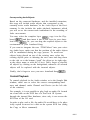
Digidesign Hardware
The Digidesign Hardware Setup dialog box contains all the
important System settings for your Digidesign hardware.
This is where you determine whether Logic will use the
analog or digital inputs when recording.
8-9
Chapter 8
Audio Driver
You can also check whether there are any communication
problems with your hardware-for example if your hardware
is not being recognized properly.
If you own several pieces of Digidesign hardware, you can
select from among them here.
Opening the Setup Window
You can open the Setup window from within the Audio window
by selecting Options > Digidesign Hardware Setup.
Select Card Type
This is where you select the card whose settings you want to
adjust. Please note that Pro Tools III hardware can be treated
like a Session 8 card, if you wish.
Cards to Use
If you have more than one card of the same type, this is where
you select the one whose settings you want to change, by entering the relevant PCI or NuBus slot number from a flip menu,
showing all the possible numbers.
Interface Options
This is where you make the settings for a given card.
Interface
Some Digidesign systems offer you a choice of audio interfaces,
when you buy them. You set the kind of interface you’re using
from this box.
Sample Rate
This is where you set the sample rate you will be using in your
recordings. All the audio files you record with Logic (or any
other software) will be recorded at the rate you enter here. You
8-10
DAE
can select either 44.1 or 48 kHz This parameter corresponds to
the setting in the Audio menu.
Sync Mode
This is where you select the source for the system’s clock signal
(or bit clock-pulses sent out at the sample rate frequency).
You have the following options:
- Internal The Digidesign hardware’s internal sync signal is used. It runs
at the frequency you’ve selected in the Sample Rate box above.
@I
The following note applies to ProTools only:
In a TDM system, only one of the cards determines the sync rate; the card in the
NuBus or PCI slot with the lowest number. This shou/d be the Disk I/O card, You can
tell which is the “Master sync card” by its glowing red LED.
-
Digital -
The sync signal received at the digital input is used.
Any digital output, whether AES/EBU or S/PDIF is constantly sending clock information, even if a signal is not passing through it. When
this setting is on Digital, the sync signal is used by the Digidesign hardware, not only when recording, but also as a sync clock for the whole
system for playback. If this box is set to Digital,please be sure that the
digital device connected to the input is never turned off, or you will Lose
your system sync signal.
For example, if you are using a portable DAT recorder that saves
power by turning itself off when not in use, you should select Sync
Mode: Internal immediately after recordingfrom thedigital input.
CH 1-2 Input
This is where you choose whether you want to use the analog
inputs (for which you select the Analog setting) or the digital
inputs (for which you select Digital).
8-11
Chapter 8
Audio Driver
If you are using an audio interface with more than one pair of
digital inputs (e.g. an 888 I/O), you will also be able to select
any of the extra input pairs from here.
Swapping Digidesign Hardware
If you have more than one kind of Digidesign hardware
installed in your system (for example Pro Tools and Session 8),
you can swap between the different types by selecting Options
> Exchange Digidesign Hardware from the Audio window
(provided the Session 8 card is the first card in your computer).
Pro Tools can read audio files from the hard drive attached to
the Session 8 card.
Setting a Level for Recording
In a studio, the recording level will normally be set at the bus
fader on the mixing desk (or directly at the sound source). The
recording machine should be set so that a level of 0 VU (Volume
Units) corresponds to the relevant reference level of +6 dBu
(radio), +4 dBu (professional studio) or -10 dBV (home recording).
However, if in certain situations, you need to be able to set the
recording level at the input of Logic, some HDR hardware will
allow you to do so:
Open the Audio window and select Options > Digidesign
Hardware Setup,
Click Other Options.
You can now set the recording level for the AudioMedia card.
On a ProTools system with the 888 I/O audio interface, you can
calibrate the recording level, using the “Calibration Tool” software supplied by Digidesign. For example, this is very useful if
you want to set the reference level to give you greater headroom.
8-12
DAE
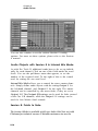
Session 8 / ProTools Project
The first time you start the program with Session 8 or ProTools
Project hardware, and DAE Version 2.95 or later, Logic asks
which driver mode should be used: Project or Session 8.
The Audio > Audio Hardware & Drivers > Use Project Driver
Mode for Session 8 System option means you can swap modes
later.
Advantages of Project drivers:
0
Allows scrubbing of up to 2 audio tracks
I/O routing for every track, directly from the audio objects
Up to 4 sends per track
Disadvantages of Project drivers:
Internal/External mix modes not available
Routing (with Studio Interface) not available
Only 4 EQs available in total (spread over all 8 tracks).
To help you decide:
If you want scrubbing, use Project driver mode.
If you want 8 EQs and Session 8 routing, use Session 8 mode.
0
Plug-in Start Window
Whenever you start TDM Plug-ins, a small status window
opens. If there is a problem, this window should show which
Plug-in(s) are the cause. If you want to disable this window, you
can switch it off, by selecting Audio > Audio Hardware & Drivers > DAE/TDM > TDM Setup Indicator (default: on).
Session 8 Routing
You can determine the Session > routing from the audio object.
8-13
Chapter 8
Audio Driver
You use this window to set the various Session 8 routing
options. For more on these options, please refer to the Session
8 manual.
Audio Objects with Session 8 in Internal Mix Mode
As with Pro Tools II, additional sends have to be set up individually for each channel. Click on one of the fields under the word
Sends. You use the pull-down menu that appears, to set the
number of the required send. To the right of this is the control
used for setting the aux send level.
Internal Mix Mode allows you to control the stereo master channels. Simply define audio objects with the setting Output 1 for
the left-hand channel, and Output 2 for the right. The master
channels can be controlled by one stereo fader, if they are set to
Output 1-2. The Output 3/4 settings can be used for fader control
of the Cue L/R channels, while the Output 5-8 settings can be
used for Aux Master Send controls.
Session 8: Points to Note
The Session 8 Mode is available with Logic Audio Gold, but not with
Platinum-for technical reasons. Platinum-customers can use the
8-14
CBX
Gold version without any disadvantages. Platinum supports TDM
system instead.
Overviews
Session 8 hardware cannot calculate, or display any overviews
(the Logic graphic files that represent the waveforms you store)
while recording. The overviews are created immediately after
recording stops. Once you’ve finished recording, however, the
overview calculation is carried out “in the background”, so you
can engage other functions while the waveform display is being
created-you don’t have to sit and wait.
Scrubbing
Audio scrubbing is not possible with Session8.
Sampling Rate
Session8 has two fixed sampling rates: 44.1 kHz and 48 kHz.
This means that you cannot calibrate it to external timecode, as
this function varies the sample rate to match the existing timecode. It’s possible that Digidesign will revise this part of the
DAE software, to make Session 8 compatible with this function
in a future version. As a user, you should remain in close contact
with Digidesign, so you can enjoy the benefits of the latest
available software updates.
8.4 CBX
Logic Audio Platinum supports the h CBX-D3 and CBX-D5
hard disk recording systems by Yamaha.
CBX-D3
If the CBX-D3 operating system software is not yet installed,
LOGIC Audio automatically installs it. While it does this (it
8-15
Chapter 8
Audio Driver
happens after booting up LOGIC Audio), the message "Initializing CBX" will appear on the screen.
The CBX-D3's sample rate can be calibrated to an external
SMPTE signal, or external MTC. Please note that the external
clock source should run at the same speed when calibrating, as
it will at mixdown The best way to insure this is to calibrate
immediately before mixdown.
Using a CBX-D3 and -D5 together
Please give the CBX-D3 the lower SCSI-ID.
In the Audio > Audio Hardware & Drivers window, select Continous Playback under CBX Driver Mode. If the hard disk then
seems too slow, change the setting to Mixed Mode.
Restrictions
Level Metering while Recording
The current version of the CBX operating system software does
not allow level metering while recording. This is not the fault of
LOGIC Audio. Instead of the correct level, the meters on CBX
audio objects will cycle up and down to show activity. Please
use the level meters on the CBX itself.
Overview
The calculation of the Overview waveform display in the
Sample Edit window only takes place after recording.
Just to remind you: the overview calculation always runs in the
background, so you can continue to work while it is calculated.
Double-clicking on the overview float window opens a dialog
box, which can be used to do the following:
break off the calculation (Abort),
carry on calculating (Continue),
8-16
DR 8116
or complete the calculation more quickly by bringing it into
the foreground (Finish). If you select this option, you will not
be able to perform other tasks while the overview is calculated.
Pan
CBX-D3 hardware does not have panning facilities. Individual
tracks are hardwired to the outputs with the same number as
the track.
I
Short Regions
Short sections (either regions, or selected areas in the Sample
1 Edit window when the playback monitor and cycle mode are
both engaged) should not be shorter than about 7000 samples,
if you want them to play back correctly. If you have a badly frag1 mented or slow drive, this minimum length could be as much as
twice as large. Perfect reproduction of sections shorter than this
, cannot be guaranteed.
8.5 DR 8/16
Logic supports the DR 8 and DR 16 hard disk recording
systems by Akai. Please note the following limitations:
The DR is the clock master, meaning Logic Audio Platinum
is slaved to MIDI Time Code (MTC). Under Options >
Settings > MIDI Options, you should set “MIDI Machine
Control (MMC)". MIDI and SCSI connections are required.
Logic Audio Platinum saves the current playlist found in the
DR. When quitting Logic Audio Platinum, it will prompt
you to send back the original playlist found when Logic
Audio Platinum was launched. This option can be switched
off under Audio > Audio Hardware & Drivers > DR8/16 >
Restore original playlist before quit.
Logic Audio Platinum is able to display the output levels for
each audio track, reading them from the DR through SCSI.
8-17
Chapter 8
Audio Driver
This may cause SCSI noise. You can switch off this function
under Audio > Audio Hardware & Drivers > Request Levelmeter thru SCSI.
The DR has its own disk(s), the contents of which are invisible to the Mac. For this reason, the DR file references are
mirrored on the Mac bootdrive in a folder named "(DRFiles)“. This folder is automatically updated to the current
state found in the DR everytime Logic Audio Platinum is
launched, so you don’t need to be concerned about it. These
“Alias” files are needed to save basic information, and the
overview data. The files are small.
Arrange:
Logic Audio Platinum allows you to grab the whole playlist
from the DR, and adds all regions to the Arrange in one operation. Select Audio > Akai DR8 > Get complete playlist from
DR8/16 . This is useful if you have recorded into the DR
outside of Logic, and wish to begin working with that recording in Logic. This is an update, existing regions are replaced
by the new ones.
The same is possible for one, selected audio track. (Arrange
> Options > Audio Setup > Get playlist of selected track
from DR8/16).
Any new recording is to be handled on the DR itself. When a
recording is finished it is easy to grab the new recorded
regions using the above described functions.
To update the DR's playlist to the new or changed regions,
the whole playlist must be sent from Logic Audio Platinum
to the DR. This happens automatically, after a short delay.
The DR stops if this happens during playback.
View:
Logic Audio Platinum gets the overview data from the DR for
each file. The resolution is ten times smaller then is normally
the case in Logic, but it is enough to see what’s going on.
8-18
DR 8/16
Audio window:
All DR files used in the Arrange are automatically added and
displayed in the Audio window as usual.
The Audio window allows all DR Files to be added in one
operation, using the menu entry Audio File > Add all DR8/16
Files. New regions can be created, edited and added to the
arrange as usual.
The DR files can be renamed with the DR limitation of 10
characters. (Note, that sessions created within the DR itself
might use these files).
Selected audio files can be deleted using Audio File > Delete
File(s). This helps to recover disk space within the DR.
(Note: this operation can’t be undone).
?
Selected audio files can be copied to a Mac drive by using
Audio File > Copy File(s) > SDII or AIFF. Note, that this can
take a while, due to the SCSI performance of the DR (see
the section Sample Edit below).
Environment:
As with other audio systems, audio objects are created for the
DR tracks.
With the current DR firmware, volume and panning changes
are sent to the DR thru SCSI. This is slow, but this behavior
may be changed when the MIDI Sysex structure is made available by Akai.
Sample Edit:
It is possible to open the Sample editor, but you will be warned
(an alert is given the first time): that the read/write performance
(speed) is very poor. If you start a process, it can be aborted by
typing @a. This behavior is not due to any a problem with
the Mac or Logic Audio Platinum, but is a limitation in the
DR's architecture.
8-19
Chapter 8
Audio Driver
8.6 1212 I/O
System Requirements
You need a PowerMac, or MacOS compatible computer with
PCI expansion slots to run a Korg 1212 I/O. Be sure to consult
the manufacturer’s documentation to ensure that all equipment
is installed and functioning correctly.
Please make sure that the System extension "1212 I/O" is in the folder
“Extensions ", inside your System folder Please use version 1.1 (or
higher). Ask your dealer or Korg distributor an update, if necessary.
Features
1212 with Logic
Logic Audio Platinum currently supports operation with one
1212 I/O card. This card has 8 inputs and outputs in ADAT
Optical Link Format, 2 inputs and outputs in S/P-DIF format,
and 2 analog inputs and outputs. All inputs and outputs can be
used in parallel.
Audio Tracks
If the 1212 driver is switched on, whenever you create a new
song, all the necessary audio objects are created automatically.
You can copy this Environment layer into your Autoload Song.
Bit Depth
The Korg 1212 S/PDIF in and outs support 20 Bit-the other
inputs and outputs (Analog, ADAT) only deliver a 16 Bit signal.
Logic Audio Platinum supports 20 Bit recording and playback,
by recording 24 Bit files, the last 4 bits of which are ignored.
8-20
1212 I/O
De/Reactivating Drivers
If you wish to run Logic without the 1212 Extension, or any
other audio drivers-in other words, simply as a MIDI
program-do the following:
Open Audio > Audio Hardware & Drivers
Deactivate the check box next to “Korg 1212 I/O”.
Quit Logic.
The 1212 Extension will be deactivated on the next program
start. Less RAM is required when the driver is deactivated. To
reactivate any installed driver, simply activate the appropriate
check box.
Special Functions
Input Gain
The Korg 1212 I/O allows the regulation of input gain. Open
Audio > Audio Hardware & Drivers, and select an appropriate
value between 0 (off) and 255 (maximum).
Synchronization
In the dialog window Audio > Audio Hardware & Drivers you
can select between these Word Clock sources: Internal, S/PDIF, ADAT.
Audio Objects
Input Routing
In every Track Object, you can select the input, by using the
top button in the I/O section.
8-21
Chapter 8
Audio Driver
Output Routing
In every Track Object, you can choose the output pair, by using
the lower button in the I/O section. Select either the left (odd)
or right (even) channel of the output pair, by using the Pan
control.
8.7 TDM Hardware
Logic Audio Platinum (not Gold) allows you to make use of the
TDM functions supported by ProTools III, ProTools 2 4 or Mix
Plus.
What is TDM?
TDM stands for “Time Division Multiplexing”, the timeinterlaced transmission of several digital audio signals through
one data bus. This bus system is physically isolated from the
computer system bus, and runs between the individual TDMcapable plug-in boards. 256 digital audio signals with a word
length of 24 bits each, can be transmitted on the TDM bus,
comprising the signal paths within a virtual mixer. These signal
paths are necessary to insert plug-ins, which are calculated on
the DSP card (DSP = Digital Signal Processor), into the individual channels, or to select them through auxiliary buses, or to
direct the 8 digital outputs of a SampleCell II TDM card to the
virtual mixer.
Please note, that with the ProTools III hardware, you can only
record if the audio hard drive is connected to the disk I/O card.
A hard drive connected to the computer’s SCSI bus cannot be
used. The disk I/O card has its own, independent SCSI-Bus,
even though the “Mount Digi" software included with Digidesign or the “Digidesign System INIT" show the connected
disk(s) on the MacOS desktop. The newer ProTools D24 and
ProTools Mix cards no longer use their own dedicated SCSI
bus, and can use any drive mounted to the System bus.
8-22
TDM Hardware
However, you should always use a drive from the approved list
provided by Digidesign.
System Requirements
To operate with TDM support, you will need a Macintosh,
Power Macintosh, or a MacOS compatible computer with properly installed ProTools III (PCI or NuBus), ProTools 2 4 or
ProTools Mix audio hardware.
In order to utilize the 24-bit capacity of ProTools 2 4 or
ProTools Mix, Logic Audio Version 3.012 (with an installed
TDM Extension), or Logic Audio Platinum 3.5 or higher is
needed.
Logic Audio Gold is not compatible with ProTools 24 or
ProTools Mix hardware. ProTools III-Hardware, however, can
be run with Logic Audio Gold (without TDM capacity- like a
Session 8 System).
We recommend that you ask your Digidesign dealer to install
the ProTools hardware, and to configure your computer.
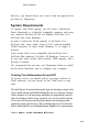
Turning Your Extensions On and Off
If, for any reason, you should wish to run Logic without its
TDM functions, you can switch off the TDM driver at any
time.
This facility can be particularly useful if you are booting up Logic with
only a small amount of RAM allocated for its use, if you are using a
slow computer or if the necessary hardware is temporarily unavailable (in another studio, being repaired, etc.). If you switch off the
driver you will also prevent any associated error messages from
appearing when you boot up. These always appear if an activated
driver cannot find its associatedhardware anywhere in your system.
Select Audio > Audio Hardware & Drivers.
8-23
Chapter 8
Audio Driver
Click on the check box by the word "TDM" (see above).
The "x" will disappear, and you can now use your ProTools III
hardware like a Session 8 system.
You may disable the entire DAE driver, using the same steps, except
that you should click on the check box to the left of the word DAE in the
line above. After disabling all audio drivers, you can use Logic exlusively as a MIDI program. This is particularily useful if the computer
has no audio hardware, of if the existing audio hardware will be
controlled by other software during sequencer operation.
Switching the Driver Back On
To turn the TDM or DAE drivers back on, just click again on
the same checkboxes. However, before you can make use of
TDM or DAE again, you will have to restart Logic.
8-24
TDM Hardware
Object Parameters of TDM Audio Objects
For general information on the audio object parameters, see the
section The Object Parameter Box on page 6-104.
Cha
The Channel parameters on TDM audio objects have a few
extra settings:
When this is selected, the audio object becomes a bus fader, for
example when in use as part of a subgroup. You could for
instance, route several track objects’ outputs to buses 7/8, and
then set the Bus-7/8 object to use the physical outputs 1/2. You
can then use the Bus object to adjust the level of the subgroup
(7/8), which will be sent to the master output (l/2).
Aux
The Aux object is a variable (input and output) object. If you
use one of these objects to handle the signal from Input 1, this
will have the same effect as using an Input/ object.
The advantages of an Aux object are that you can:
assign various insert effects to several Aux objects, and apply
them to Input 1 (whereas an Input-1 object could be used
only once),
change the signal source for the Aux object at any time (all
other objects have a fixed signal source; e.g., Track, Input or
Bus).
Initially, only Aux 1 and Aux 2 are available in the Selection
Menu. Once you have used all of the available Aux objects,
Logic Audio will make more available as needed.
You will probably use an Aux object primarily to set a Bus as an
Input, on which Aux Sends of various audio tracks will be transmitted.
8-25
Chapter 8
Audio Driver
You can also use the Aux Object with a bus input as Aux Master
Send for an external effects device. Select an output of the
audio interface to be used as Aux object output. Then connect
the input of the external effects device with this output. Now,
you can direct the output of the external effects device back to
the virtual mixer.
~Editing Plug-ins
Plug-in Key Commands
With Logic 3.0 and later versions, you can control Plug-ins with
their own key commands. For example, if you activated an area
of the TDM Plug-in with the mouse, you can enter numeric
values in that section. To avoid accidental entries, you can click
on the background of the Plug-in window, or press the @ key,
after you have changed a parameter.
Any key commands that are not used by the Plug-in, will be
passed on to Logic. Under normal conditions, this ensures that
functions like Start and Stop will continue to work. If this is not
the case, you may use several new options to define that only
certain key combinations will be passed to the Plug-in, while all
other key presses on the computer keyboard will be received
by Logic. These options are located in Audio > Audio Hardware & Drivers, in the DAE section (“Pass keyboard
events..." ) .
Plug-in Setups (Settings, Effect Programs)
All TDM Plug-in settings are saved with the song, and will be
automatically restored when the song is loaded.
You can also use Plug-in Setups as a practical means to manage
the parameters of a Plug-in. This method is comparable to the
storage locations of an external effects device, combined with a
clipboard for effects parameters.
8-26
TDM Hardware
In the header line of the Plug-in window, you can open the
Setups pull-down menu by clicking on the arrow button:
Copy Setup
copies all parameters onto its own independent
Plug-in clipboard. They remain here, until the
next time you select Copy Setup. This does not
affect the global Logic clipboard.
Paste Setup
If you have opened a plug-in of the same type,
you can paste the parameter set from the plug-in
clipboard. This allows you to quickly set up
several plug-ins of the same type, or exchange
effects settings between songs.
Save Setup
This allows you to save all the plug-in parameters to disk. This is useful if you have created
a special sound effect, which you want to have
available for future use.
Load Setup
For loading stored parameter sets from disk.
The file selector box shows only setups for
compatible plug-in types. It can also read the
Digidesign format for TDM plug-in settings.
The parameter setups of a plug-in can also be copied between
the plug-in’s mono and stereo versions, and the Digidesign format for plug-in Settings can be read (the supplied effects programs of most plug-ins are saved in this format). When loading
Setups, through the arrow menu in the plug-in windows, Logic
automatically displays the corresponding files in the file selection box. Settings files are usually located in a “Settings” folder,
within the DAE folder. The name of the last preset chosen will
be indicated by a dot in the menu listing.
DAE Plug-in Folders
Starting with DAE 3.1, the DAE folder contains only one
“Plug-ins” folder which can store both AudioSuite and TDM
Plug-ins.
8-27
Chapter 8
Audio Driver
Disabled Plug-ins
If you haven’t done so, create a folder with the name “Plug-ins
(unused)” in your DAE folder (or in any other location). Then
move all TDM Plug-ins not used on a daily basis, into this
folder. This will speed up the DAE (and Logic) boot process.
Support of TDM Plug-in Sidechains
Some TDM Plug-ins, such as Noise Gates or compressors,
allow Sidechain Signals from other Tracks or Busses. This
option is available in Logic Audio.
Automation
For detailed information on this subject, read the chapter
Chapter 6: Mixers, Effects and Audio Objects.
As with other audio objects, TDM objects can be automated,
although only adjustments made to the controls on the first four
plug-ins can be recorded. Up to 16 parameters may be remotecontrolled on each of these four plug-ins.
A fixed hierarchy has been adopted for the controller numbers
used to automate plug-in parameters, based on the position of
the plug-in. Plug-ins are counted from the top downwards.
1.Plug In
Controller # 64 to # 79
2.Plug In
Controller # 80 to # 95
3. Plug In
Controller # 96 to #111
4.Plug In
Controller #112 to #127
1Dynamic Controller Assignment
To automate the parameters of plug-ins with more than 16 parameters (e.g., D-Verb, DPP1 or JVP), Logic Audio manages the
number of required controllers dynamically.
The “base addresses” (the first controller numbers: 64/80/96/
112) remain unchanged. However, if you have activated only
8-28
TDM Hardware
one plug-in, in the first position (first slot), you can automate 64
parameters in this location: 64-127.
If you insert an additional plug-in on the second slot, controllers
64-79 (16 parameters) will be available for the first plug-in,
and
80-127 (48 parameters) will be available for the second plugin.
If you use one plug-in in the first slot and one plug-in in the
third slot, 32 controllers (64-95 and 96-127) will be available for
each of the two plug-ins.
To find out which controller number controls which parameter
for a given plug-in, open the Event List and click on a controller to select it. A list of all parameters that can be automated will
appear.
In the Event List, the parameter names of all known plug-ins
are shown in plain text.
Caution: Not all TDM Plug-ins (in particular older plug-ins)
allow for problem-free real-time automation of parameters. In
such cases, the basic settings still can be saved together with
the song, however, the dynamic automation of the parameters
during song playback is not possible.
Automation Process
The automation of plug-in parameters works the same as the
regular automation described in the manual.
Just try it yourself. Select a track assigned to the A-playback
instrument, and start recording. Open a plug-in, on an audio
object insert, and move an operating control of the plug-in. Your
moves will be recorded as MIDI commands, which can be
recalled and edited.
This procedure can be used to detect which controller numbers can be
automated graphically with Hyperdraw Using the Auto Define Hyper8-29
Chapter 8
Audio Driver
draw function (which also is available as a key command), Hyperdraw will set itself automatically for the first used controller.
Some plug-ins, like the Digidesign Plug-in “Dynamics”, respond to the
controllers they receive "from the outside”, but they will not automatically update the operating control display. Therefore, Logic Audio will
redraw the complete plug-in after a certain period.
Plug-ins in objects like “Input”, "Aux", “Output”, or “Bus”
can be automated as follows: Create a channel splitter in the
environment New > Channel Splitter), and use cables to
connect its channels with the respective audio objects. Insert
the channel splitter into the Arrange window just like a track
instrument (the same way you inserted the A-playback instrument earlier). Name the channel splitter something like “Bus
Playback”, so that you can distinguish it from the existing Aplayback instrument.
Functions, Special Features
Deleting Objects
If you delete an audio object in the environment, by selecting it
and pressing l?Zi~, the level of this object will be set to “Zero”
(minus infinite dB). However, “Output” or “Bus” objects are
an exception: When deleting these, the level will be set to 90 (0
db); otherwise, the tracks routed to this output would not be
audible any longer. The other settings (send paths, plug-ins,
and sound control) are not deleted but merely muted. This way,
Logic Audio automatically ensures that DSP processor capacity
will not be wasted. As soon as the object is displayed again in
the environment, the last selected level will automatically be
restored. In the TDM System, the Send, and Plug-in will be
restored.
8-30
TDM Hardware
Special Features of ProTools III with 32 or 48 Tracks
Logic Audio supports 32 or 48 track ProTools III systems, with
more than one Disk I/O card, and 64 tracks with the ProTools
Mix system.. Please remember the following, when operating a
ProTools III system with more than 16 tracks:
Every Disk I/O card has its own SCSI bus. This means that
tracks 1-16 can only play back audio files from hard drives
which are connected to card 1, tracks 17-23 only from disks
connected to card 2 etc. The same applies to recording. The
recording path of every Disk I/O card is managed separately in
the Audio window through the dialog box Audio File > Set
Record Path...
Logic will notify you in the Audio or Sample Edit window if
you accidentally try to playback an audio file on a track from
another card. Such “erroneously assigned” audio files will not
play in the Arrange window.
Since MIDI cannot differentiate more than 16 channels, you
will need additional Channel Splitter objects (“A-Playback”
instruments) for the automation of more than 16 tracks on any
TDM system. If you want to create a completely new song
(instead of opening a copy of your Autoload Song), e.g., with
alt, Logic will automatically create the following Environment Setup:
Tracks 1-16 are connected with channels 1-16 of the Channel
Splitter A-Playback,
Tracks 17-32 are connected with channels 1-16 of the Channel
Splitter B-Playback
Tracks 33-48 are connected with channels 1-16 of the Channel
Splitter C-Playback
(Initially “A-Playback” stood for "Audio-Playback". If you don’t like the new name,
you can easily rename the channel splitter objects.)
8-31
Chapter 8
Audio Driver
If you operate more than one audio interface (through additional Bridge I/O cards), the additional interfaces are called "b",
"c", etc.; for example, “Out 882b 1-2".
Special Features of ProTools 24
The most significant new features of PtoTools 24 are:
Under Logic you now can also record and playback with 24
bit word length.
Provides up to 32 audio tracks. For system requirements,
please see the Digidesign documentation.
A core system may have 24 inputs and outputs (versus 16
with ProTools III PCI, or 8 with ProTools III NuBus).
ProTools 24 does not have its own SCSI bus. It uses the
computer’s SCSI bus. Therefore, you should read QT
movies and audio data not only from separate hard disks, but
also from hard disks connected to different SCSI busses.
For the operation of ProTools 24 with TDM, Logic Audio
Platinum is required. Unlike ProTools III, it cannot be run as
if it were a Project or Session8 system, with Logic Audio
Gold. However, you can run a ProTools 24 system in Logic
Audio Gold, using the Direct I/O driver. This gives you no
access to TDM functionality, so if you have such a system, it
is highly recommended that you upgrade to Logic Audio
Platinum.
TDM Mixer Plug-in
Please be sure that there is only one Mixer Plug-in in the
“Plug-ins” folder (within the DAE folder), which will be either
the 16-bit version or the 24-bit version.
24-bit files can also be played back through the “16-bit optimized mixer” (or vise versa). However, only the “24-bit optimized mixer” can adequately handle the resolution of recordings in 24-bit format.
8-32
TDM Hardware
The 24-bit mixer requires more DSP capacity than the 16-bit
mixer. Therefore, you may get a DAE error message ("DSPs
maxed out”), when opening older songs with maximum DSP
load, after the upgrade to ProTools24. In this case, you should
use the 16-bit mixer plug-in.
Changing Global Bit Depth
If ProTools 24 hardware is being used, Logic will ask at the
initial program start, whether you want to use 16-bit or 24-bit
word length. Later, you may change the “Global Bit Depth” in
the dialog box Audio > Audio Hardware & Drivers from 16-bit to
24-bit, and vice versa.
N
In most cases, a resolution of 16-bit is adequate for the individual tracks of a regular
multi-track production, This setting requires less space on the storage medium, and
also less data throughput capacity on the hard disk, to play the same number of
tracks. The 24-bit format is mainly advantageous with highly dynamic material (e.g.
classical music productions),
Program Start
If you are loading a song with different word length audio files,
Logic will display a warning. You can change the word length
(see above), or you may convert the audio files.
Please note that the conversion of 16-bit recordings to 24-bit recordings does not
bring any sound quality improvement, while a conversion from 24-bit to 16-bit
results in the irrevocable loss of the added dynamics possible with 24-bit files.
Converting the Word Length
In the Audio window, select all of the files to be converted.
For the selection, it would be useful to sort the audio files by their word length (bit
depth) (see above). Then select all files to be used in the arrangement with [Edit >
Select used].
Select Audio File > Copy File(s).
In the following dialog box, you have the option to set the word
length (bit depth).
8-33
Chapter 8
Audio Driver
After confirming the dialog, the audio files will be copied-the
copied files will have the selected word length.
Logic now will ask you if the references in the current song
should be changed to reflect the copied files, instead of the
original files.
If you want to work immediately with the current song, you
should confirm this dialog.
Save the song with a different name by selecting File > Save
as... if you want to keep the references to the original files in
the original song.
Sample Editor
All functions of the Sample Editor can be used with 24-bit
audio files. You can even exchange sound material in either
direction between 16-bit files, and 24-bit files by using the
Copy and Paste commands.
Please note that Premiere Plug-ins use only 16-bit resolution
(you can still edit 24-bit files). AudioSuite Plug-ins support 24
bits.
Simultaneous Operation of Different
Hardware
Please note the following, if you want to use a TDM System
and other audio hardware at the same time.
Generate Audio Mixer
New Song
With the selection of the command File > New (or Bm), a copy
of your Autoload Song will be opened. If you want to open a
completely new song with standard defaults (Default Song),
just press ~@$7iJ.
8-34
TDM Hardware
Corresponding Audio Objects
Based on the connected hardware, and the installed extensions,
this song will include audio objects that correspond to the
currently active audio hardware, in the Audio layer of the Environment. It also includes the audio playback instrument, which
you will set as the current track instrument for the recording of
fader movements.
You may select the complete layer (mm), copy it to the Clipboard (ma), and then insert it into a new layer in your Autoload Song (ma). Or, you can drag the required objects to the
environment of your Autoload Song.
If you want to integrate the new “TDM Mixer” into your existing Audio layer, make sure that the position of the audio objects
will be maintained during the copy process. To avoid new
objects being placed on top of the existing ones, select the
existing objects prior to inserting the new ones and drag them
to the side or to the bottom (“grab” the object at its right edge,
at the object name or with the •J key). Don’t forget to deselect
all objects by clicking on the background; otherwise all selected
objects will be replaced with the inserted objects.
Finally, don’t forget to save your new Autoload Song (l%J?J).
Control Playback
To control playback in the Audio window or in the Sample Edit
window, make sure to select the correct corresponding hardware and channel, under Channel and Device (at the left side
of the window).
For example, it is not possible to play back an audio file located
on a hard disk on the SCSI bus of a ProTools III System
through the internal Mac hardware, since only it can access the
SCSI bus of the I/O card.
In order to play such a file, the audio file would have to be physically copied or moved to a disk on the system SCSI bus (using
the Copy or Move command).
8-35
Chapter 8
Audio Driver
Total Number of Audio Tracks
When operating different audio hardware simultaneously, the
number of possible tracks cannot be determined by merely
adding them up. This is especially true if the connected
systems have to use the CPU processor’s power. This is the case
primarily in AV mode, but also when using DAE.
The simultaneous operation of DAE hardware and AV audio
tracks will result in a significant reduction in the number of
usable AV tracks. However, stand-alone systems, like the Akai
DR-8/16, cause only a minor load increase on the CPU.
The arithmetically added number of tracks may also be
reduced, if the connected systems access the same SCSI bus.
This is the case, for example, when using AV tracks and CBX
hardware at the same time.
This effect may be significantly reduced (i.e., the total number
of tracks increased) by using different hard drives for the various systems (e.g., AV reads from an internal drive, and CBX
from an external drive).
On the other hand, the simultaneous operation of ProTools III
and CBX (=4 tracks or 8 tracks with two CBXs) presents no
problem at all.
We recommend, however, that you avoid the use of an internal
hard disk for hard disk recording, if possible.
Digidesign Adat Bridge Interface
If you want to use the Digidesign Adat Bridge Interface, you
need DAE Version 3.2.3 (or higher). The Adat Bridge Interface
is a 19" unit with two optical Adat inputs and outputs providing
16 channels, where channels 1 and 2 also act as AES/EBU and
S/PDIF ports.
8-36
TDM Hardware
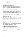
Hardware Setup
- Interface Options:
Interface Port:
Each of the two groups of up to eight channels can be individually connected to a Disk I/O or a PCI DSP Farm. The PT24
Disk I/O has two interface sockets. You can select the bridge
interface in the Hardware Setup menu.
Hardware Setup
Interface Options:
Card:
Interface Port:
Interface:
tKIFlT Bridge Fl cl-81 7 1
Sample Rate:
Sync Mode:
FiDRT Optical v
Digital Format:
Ch 1-2 Input:
Other Options
8-37
Chapter 8
Audio Driver
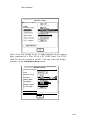
Playback Engine Setup
7Playback Engine: -r Interface Options:
@ d24
Card:
Interface Port:
Interface:
m
flOFlT Bridge B cl-81
I-,
Sync Mode:
rx$Gq
Digital Format:
-1
Ch 1-2 Input:
[--x$xq
Other Options
8.8 Direct I/O
Until now, Digidesign hardware has always been addressed via
DAE (Digidesign Audio Engine). Digidesign has now released
hardware like “Project II”, that is not supported by DAE. The
new Audio Engine has been developed to use these cards with
Logic Audio. As the Direct I/O interface supports other Digidesign hardware as well, the driver is called “Direct I/O” instead
of “Project II”.
Please note that the system extension Digisystem INIT 3.4 or
higher is required. This system extension is shipped with the
card, but is also available from the Digidesign distributor in
your country, or from the Digidesign web site www.digidesign.com).
the way: users of other Digidesign PCI cards, (e.g. Audiomedia III or ProTools Project) may also benefit from Direct I/O.
You achieve a higher number of tracks (if your CPU is fast
enough), and gain access to Logic Audio’s internal effects and
VST Plug-ins. Even if you are using a ProTools III Core
system, you may use Direct I/O, at least if you have a powerful
CPU. However, please note that no TDM functions will be
By
8-38
Direct I/O
available. Furthermore, you should only play back audio files
from the hard drive attached to SCSI bus of your Power Macintosh, and NOT from any drive attached to the SCSI bus of the
Digidesign card when using Direct I/O. Newer and larger
ProTools 24 systems can be also be run via Direct I/O, instead
of DAE. However, as you then lose all TDM functions, it does
not really make sense.
In order to activate the audio driver for Digidesign Project II, or
other hardware, go to the main menu and select Audio > Audio
Hardware & Drivers > Direct I/O . Here are descriptions of the
parameters you will find in the “Direct I/O” section for the new
Audio Engine:
:
I/O Buffer Size
This parameter, which affects Direct I/O, governs the latency
and the performance of the card. A value of "1" is an ideal
setting for good performance and reasonable fader response.
Smaller values reduce the monitoring delay and the fader
response time, but also reduce the number of audio tracks and
the performance of plug-ins.
Use 16 Ins & Outs
The Project II card allows you to use two audio interfaces, with
8 inputs and outputs each. If you have only one interface,
please switch this setting off. This saves memory, and optimizes overall performance. You should only switch this setting
on when actually using two interfaces.
Digidesign Hardware Setup
In the audio window, with Options > Digidesign Hardware
Setup, you can open a dialog that allows you to select the audio
interface, and to switch between analog and digital input. The
equivalent dialog box for setting up DAE is only available
when actually using DAE to run your Digidesign hardware.
The Direct I/O driver cannot be used simultaneously with
DAE.
fl
8-39
Chapter 8
Audio Driver
8 . 9 Sonorus StudI/O
In comparison with the ASIO driver, this direct support of the
StudI/O offers the following advantages:
Better performance
More precise start when recording and playing back.
Operating Modes
The StudI/O can be operated in 5 different modes. All modes
allow 24 bit:
2x ADAT
16 In/Output channelsalways available in ADAT format.
ADAT + SPDIF
8 I/O channels in ADAT format, and two channels of S/PDIF
I/O.
ADAT + BNC
8 I/O channels in ADAT format, and ADAT-sync
2x SPDIF
Two twin channel S/PDIF I/O.
96K SMUX
8 I/O channels over ADAT with 88.2 or 96 kHz format (Platinum only).
m
With regards the other parameters that appear here, please refer to the manual of
the StudI/O
8.10 ASIO
ASIO (Audio Stream In/Out) is a common driver format introduced by Steinberg to allow audio hardware and audio software
8-40
ASIO
(in this case Logic Audio Platinum) to work together. An ASIO
driver translates the input data of the hardware into a specific
format, and transfers the data to the software (Logic Audio Platinum), which receives it as recording data. In turn, the software
(Logic Audio Platinum) transmits the final mixed signals to the
ASIO driver, which then transfers it to the hardware.
The ASIO driver is generally provided by the manufacturer of
the audio hardware.
The advantage of this sort of industry standard interface is:
New Audio hardware is compatible with Logic Audio right
away, as long as it is equipped with an ASIO driver.
The disadvantage of this sort of industry standard interface is:
To software each driver (and the hardware supported with it)
looks identical. There is no flexibility to support specific
features of the hardware. Some manufacturers ship their own
control panels, the settings of which are “invisible” to Logic
Audio.
Just like Direct I/O, ASIO support is handled by the Audio
Engine as described in the section Audio Engine on page 8-5.
The settings for the audio engine and for the ASIO driver can
be found in the Audio > Audio Hardware > Drivers > ASIO menu.
Current Driver
This is where you select the ASIO driver you would like to use.
When changing the Audio driver, it is necessary to quit Logic
and open it again.
Logic expects to find the ASIO driver in a folder named “ASIO
Drivers”, in the directory of the Logic program file.
!
This also can be an alias to an ASIO folder somewhere else
Control Panel
This switch allows you open the control panel of the active
ASIO driver, if one is available. Whether or not this control
8-41
Chapter 8
Audio Driver
panel exists depends on the manufacturer of the hardware
being supported.
Clock Source
This setting allows you to use a digital clock source from an
external device, if the hardware and the driver you are using
supports this.
ASIO Buffer Delay
Some ASIO drivers give incorrect information regarding input
and output delay. The difference from the actual value may
vary between different versions of the driver, therefore it is
necessary to allow changes of this setting. Please check our
recommendations for specific hardware systems in the
ReadMe-File on the CD-ROM.
Max. I/O Streams
This parameter is used to define a maximum of inputs and
outputs. This is needed especially for the DS2416 card, which
does not run with its 8 ins & 16 outs on machines slower then a
G3/333. The default is set to 4 ins and 8 outs for the DS2416
For others it is set to Max, which means that you can use all ins
and outs.
It’s recommended that you switch off unused I/O channels in
the driver (control panel), if you are using an ASIO driver that
supplies one.
System Memory Requirement
Changing some of the above settings increases or decreases the
required memory. The required memory is displayed on the
right side of the "ASIO" switch.
The Key Command Open System Performance... will open a
1 window that displays the CPU and Hard Disk Bus usage as a
percentage (with 100% being the maximum capacity).
8-42
8.11 Yamaha DSP Factory
The currently supported components of the Yamaha DSP
Factory System include one DS2416 card and, optionally, up to
two AX44 extension bays (4 analog ins and outs each) or an
AX16T (2 x 8 ADAT Ins and Outs). Furthermore, Logic Audio
Platinum is also ready to support up to 8 channels of one
SW 1000XG soundcard and future I/O extensions whose specifications are yet unknown. In order to use the card, select Audio
> Audio Hardware & Drivers and check DS 2416.
Features
(If you use one DS2416 only)
Up to 16 audio tracks
24 channel digital mixing disk, including
up to 4 channels for two stereo effect returns of the two internal multi-effect processors
up to 4 Input channels. Further inputs are only available
with the AX44 hardware extensions and by sacrificing audio tracks (there is a total limit of 24 channels).
Variable output routing for the stereo sum and the 4 Aux
sends. In addition, the two internal effects sends can be
used in parallel. This results in a maximum of 6 individual
outputs.
Each of the 24 channels offers:
4 Equalizer Plug-ins (fully parametric, shelving)
Dynamics Plug-in (Compressor, Limiter, Expander,
Gate)
Channel Delay
In addition, the two effect return channels each offer:
One Multi-Effect Plug-in (choose from a list of 40 algorithms)
8-43
Chapter 8
Audio Driver
Mixer
The mixer directly reflects the available DSP and routing of the
DSP Factory, as long as you use the ASIO Driver DS 2416 as
the only driver. It is defined by the feature set of the hardware,
and therefore is not completely variable. Please note that Logic
does not utilize its own audio driver, but uses Yamaha’s ASIO
driver, and the real-time effects of the digital mixer integrated
in the DSP Factory.
The default configuration of the mixer offers 16 audio tracks, 4
inputs (analog and digital input), two stereo effect returns and
two stereo output objects (master fader) for the stereo analog
and digital output of the DS 2416 card. The mixer offers 24
channels. Additional inputs always reduce the number of audio
tracks.
Fader
The faders have a different range than the faders which control
other hardware: 0 dB equals the volume controller value 127.
The value 90 equals -6dB. Unlike other audio drivers, the
fader for the DSP Factory can only decrease the volume, but
not increase it.
Inserts
Each mixer channel holds up to 4 EQs, one dynamic module,
one channel delay and one phase inverter.
EQs, dynamics modules, channel delay, and the phase inverter
are used as inserts and can be controlled via plug-in windows.
The actual signal path is not variable and goes like this: EQs -›
Dynamics - › Delay.
The plug-ins of the audio tracks are used-as is common-on
playback. However, please note that effects on the input channels (i.e. channel 17 to 20 in the standard configuration) are also
recorded. For unaffected recording you might want to set the
inserts of the input channels to bypass. ([%llZ?]-Click). On the
8-44
Yamaha DSP Factory
other hand, it might be useful to directly record EQs and
dynamics.
On the effect return channel, the internal multi-effects devices
always use the first insert slot, but EQs and dynamics can be
used in the following ones.
Sends
0
Track channels (audio tracks) and input channels have up to 8
sends. The sends labeled “Effect 1" and “Effect 2" address the
two internal effect busses.
In addition, the sends of the available outputs of the installed
hardware can also be used; e.g. output 1-4, if one DS2416 card
is installed (using an AX44/AX16 extends the choice to outputs
1-6). Please also refer to the following section on input/output
routing.
As is common with Logic’s fader, the effect sends are processed
after the fader (post-fader), but can be switched to pre-fader
using the flip menu of the active sends.
Input/Output Routing
0
Located above the pan fader is the output routing for all 24
channels. This allows you to direct the output signal of a track
to one of the outputs. The track channels (“Audio 1-16") also
feature input routing; i.e. the ability to select from which input
you would like to record.
The number of available inputs and outputs depends on
whether you have only a DS2416 card installed, or whether you
are also using the AX44 I/O box (or AX 16):
DS2416 4 inputs and 4 outputs
DS2416 + AX44: 8 inputs and 6 outputs (the two additional
outputs can only used parallel to the internal effect busses).
8-45
Chapter 8
Audio Driver
DS2416 + AX16: 8 Inputs and 6 Outputs (2 more Outputs can
be used in parallel with the internal effect busses; Recording
busses are restricted to a maximum of 8 Inputs.
A second AX44 may be used but does not increase the number
of outputs you can address simultaneously (max. 8)
Default:
Input 1 = Channel 17 = Analog In L
Input 2 = Channel 18 = Analog In R
Input 3 = Channel 19 = Digital In L
Input 4 = Channel 20 = Digital In R
Both the Analog Out and the Digital Out are addressed by
"Output 1-2".
The first AX44 (if installed) is addressed by “Output 3-4”
and “Output 5-6".
The second AX44 (installed) mirrors effect sends 1 and 2 on
its first output pair.
These default settings can be edited in the "DS2416 Routing”
window.
8-46
Yamaha DSP Factory
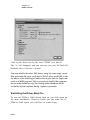
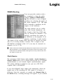
Logic
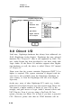
DS2416 Routing
You can open this window with a
key command or from the audio
window Options > DS2416 Routing.The left half is a sort of digital
patchbay for selecting the inputs of
the mixer channels 1-24. The right
half is basically a patchbay for the
outputs of the hardware.
The input patches can be configured with certain limitations; e.g.
the 4 inputs of the first AX44 can
only by inserted on channels 17-20
(thereby sacrificing the inputs of
the DS2416) or on channels 13-16
(thereby sacrificing 4 audio tracks).
The inputs of the second AX44 can only be inserted on channels 9 to 12 (losing another 4 tracks). The 8 outputs of the
SW1000XG soundcard (“Sub 1-8”) can only be inserted via
channels 9-16 or 17-24.
m
Please note that this window already displays some options which are not yet available as hardware, e.g. the hardware for the options "IO-A2" and "IO-B2". Logic
Audio should run with this hardware, although we were not yet able to test it as of
the release of Version 4.0.
Clock Source
The parameter Clock Source under Audio > Audio Hardware >
Drivers > ASIO allows you to switch between the use of internal
synchronisation or an external digital synchronisation signal.
The setting serial in is needed in case you use a DS 2416
together with a SWlOOOXG.
SW1000XG.
If you select Digital Logic Audio will continously check the
sample rate of the incoming S/P DIF signal. If it detects a
difference from the currently set sample rate (Sample Rate in
the Audio menu) a warning message will appear. If you confirm
8-47
Chapter 8
Audio Driver
this message with USE, the internal sample rate will be set to
the detected rate.
8-48