1
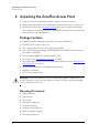
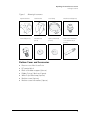
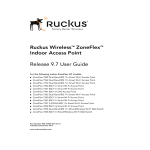
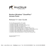
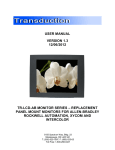
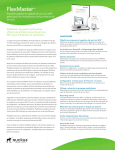
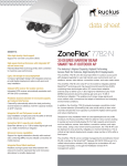
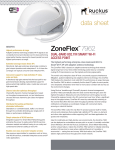
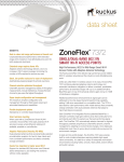
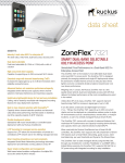
Ruckus Wireless®
ZoneFlex® 2741 802.11g
Outdoor Access Point
Getting Started Guide
Part Number 800-70180-001
Published January 2008
www.ruckuswireless.com
Contents
1
About This Getting Started Guide . . . . . . . . . . . . . . . . . . . . . . . . . . . . . . . . . . . . . . . . . . . . 1
Related Documentation . . . . . . . . . . . . . . . . . . . . . . . . . . . . . . . . . . . . . . . . . . . . . . . . . . . 1
Using ZoneDirector or FlexMaster to Manage the Access Point . . . . . . . . . . . . . . . . . . 1
2
Unpacking the ZoneFlex Access Point . . . . . . . . . . . . . . . . . . . . . . . . . . . . . . . . . . . . . . . . . 2
Package Contents . . . . . . . . . . . . . . . . . . . . . . . . . . . . . . . . . . . . . . . . . . . . . . . . . . . . . . . . 2
Mounting Kit Contents . . . . . . . . . . . . . . . . . . . . . . . . . . . . . . . . . . . . . . . . . . . . . . . . . . . 2
Bottom Cover and Accessories . . . . . . . . . . . . . . . . . . . . . . . . . . . . . . . . . . . . . . . . . . . . 3
3
Before You Begin . . . . . . . . . . . . . . . . . . . . . . . . . . . . . . . . . . . . . . . . . . . . . . . . . . . . . . . . . . 4
Prepare the Required Hardware and Tools . . . . . . . . . . . . . . . . . . . . . . . . . . . . . . . . . . . 4
Get to Know the Access Point Features . . . . . . . . . . . . . . . . . . . . . . . . . . . . . . . . . . . . . . 5
LED Colors and What They Mean . . . . . . . . . . . . . . . . . . . . . . . . . . . . . . . . . . . . . . . . . . 6
Perform a Site Survey . . . . . . . . . . . . . . . . . . . . . . . . . . . . . . . . . . . . . . . . . . . . . . . . . . . . . 9
Determine the Optimal Mounting Location and Orientation . . . . . . . . . . . . . . . . . . . . 10
Become Familiar with the Installation Components . . . . . . . . . . . . . . . . . . . . . . . . . . . 13
Decide How You Will Supply Power to the Access Point . . . . . . . . . . . . . . . . . . . . . . . 14
4
Configuring the Access Point. . . . . . . . . . . . . . . . . . . . . . . . . . . . . . . . . . . . . . . . . . . . . . . . 15
Configuring for Management by ZoneDirector . . . . . . . . . . . . . . . . . . . . . . . . . . . . . . . 15
What You Will Need . . . . . . . . . . . . . . . . . . . . . . . . . . . . . . . . . . . . . . . . . . . . . . . . . . . . 15
Step 1: Connect the Cables to the Access Point . . . . . . . . . . . . . . . . . . . . . . . . . . . . . 16
Step 2: Connect the Access Point to the Same Subnet as ZoneDirector . . . . . . . . . 19
Step 5: Disconnect the Access Point from the Power Source . . . . . . . . . . . . . . . . . . . 19
Configuring for Standalone Operation or for Management by FlexMaster . . . . . . . . 20
What You Will Need . . . . . . . . . . . . . . . . . . . . . . . . . . . . . . . . . . . . . . . . . . . . . . . . . . . . 20
Step 1: Prepare the Administrative Computer . . . . . . . . . . . . . . . . . . . . . . . . . . . . . . . 20
Step 2: Connect the Access Point to the Administrative Computer . . . . . . . . . . . . . 22
Step 3: Log Into the Access Point’s Web Interface . . . . . . . . . . . . . . . . . . . . . . . . . . . 25
Step 4: Configure the Wireless Settings . . . . . . . . . . . . . . . . . . . . . . . . . . . . . . . . . . . . 25
Step 5: Disconnect the Access Point from the Administrative Computer . . . . . . . . . 29
Step 6: Restore the Administrative Computer’s Network Settings . . . . . . . . . . . . . . 30
i
5
Verifying Access Point Operation . . . . . . . . . . . . . . . . . . . . . . . . . . . . . . . . . . . . . . . . . . . . 30
Connect the Access Point to the Network . . . . . . . . . . . . . . . . . . . . . . . . . . . . . . . . . . . 30
Check the LEDs . . . . . . . . . . . . . . . . . . . . . . . . . . . . . . . . . . . . . . . . . . . . . . . . . . . . . . . . . 31
Associate a Wireless Client with the Access Point . . . . . . . . . . . . . . . . . . . . . . . . . . . . . 31
Check the TR069 Status (FlexMaster Management Only) . . . . . . . . . . . . . . . . . . . . . . . 32
Disconnect the Access Point from the Network . . . . . . . . . . . . . . . . . . . . . . . . . . . . . . . 32
6
Deploying the Access Point . . . . . . . . . . . . . . . . . . . . . . . . . . . . . . . . . . . . . . . . . . . . . . . . . 32
Step 1: Complete the Power Connections . . . . . . . . . . . . . . . . . . . . . . . . . . . . . . . . . . . 32
Step 2: Install the Back Panel Cover . . . . . . . . . . . . . . . . . . . . . . . . . . . . . . . . . . . . . . . . 37
Step 3: Connect the Access Point to the Network . . . . . . . . . . . . . . . . . . . . . . . . . . . . . 38
7
Attaching the Mounting Brackets . . . . . . . . . . . . . . . . . . . . . . . . . . . . . . . . . . . . . . . . . . . . 40
What You Will Need . . . . . . . . . . . . . . . . . . . . . . . . . . . . . . . . . . . . . . . . . . . . . . . . . . . . . 40
Step 1: Attach the Static Bracket to the Mounting Surface . . . . . . . . . . . . . . . . . . . . . 40
Attaching the Bracket to a Flat Surface . . . . . . . . . . . . . . . . . . . . . . . . . . . . . . . . . . . . 40
Attaching the Bracket to a Pole . . . . . . . . . . . . . . . . . . . . . . . . . . . . . . . . . . . . . . . . . . . 44
Step 2: Attach the Dynamic Bracket to the Access Point . . . . . . . . . . . . . . . . . . . . . . . 46
8
Mounting the Access Point . . . . . . . . . . . . . . . . . . . . . . . . . . . . . . . . . . . . . . . . . . . . . . . . . 47
9
(Optional) Mounting and Connecting the External Antenna . . . . . . . . . . . . . . . . . . . . . . 50
10 What to Do Next . . . . . . . . . . . . . . . . . . . . . . . . . . . . . . . . . . . . . . . . . . . . . . . . . . . . . . . . . . 53
Change the Administrative Password . . . . . . . . . . . . . . . . . . . . . . . . . . . . . . . . . . . . . . . 53
Configure the Security Settings . . . . . . . . . . . . . . . . . . . . . . . . . . . . . . . . . . . . . . . . . . . . 53
Read Related Documentation . . . . . . . . . . . . . . . . . . . . . . . . . . . . . . . . . . . . . . . . . . . . . 53
ii
1 About This Getting Started Guide
This Getting Started Guide provides information on how to set up the Ruckus Wireless
ZoneFlex 2741 802.11g Outdoor Access Point on your network. Topics covered in this
guide include installation, basic configuration, and device mounting.
This guide is intended for use by those responsible for installing and setting up network
equipment. Consequently, it assumes a basic working knowledge of local area networking,
wireless networking, and wireless devices.
Related Documentation
In addition to this guide, each Ruckus Wireless ZoneFlex 2741 802.11g Outdoor Access
Point documentation set includes the following:
■
User Guide: Provides detailed information on how to configure the Access Point. The
User Guide is available for download on the Ruckus Wireless Support Web site at:
http://support.ruckuswireless.com/documents
■
■
Release Notes: Provides late-breaking information about the current software release,
including new features, enhancements, and known issues. If the information in the
Release Notes differs from the information in this guide, follow the instructions in the
Release Notes.
Online Help: Accessible from the Access Point’s Web interface, the Online Help
provides information that helps you configure the device from the Web interface.
Using ZoneDirector or FlexMaster to Manage the
Access Point
If you are planning to use either Ruckus Wireless FlexMaster or Ruckus Wireless ZoneDirector to manage the Access Point, this guide describes the required steps that will enable
the Access Point to report to and communicate with FlexMaster or ZoneDirector successfully.
■
■
To set up the Access Point for management by FlexMaster, refer to “(Optional) Set the
FlexMaster Server Address” on page 28.
To set up the Access Point for management by ZoneDirector, refer to “Configuring for
Management by ZoneDirector” on page 15.
1
Unpacking the ZoneFlex Access Point
Package Contents
2 Unpacking the ZoneFlex Access Point
1. Open the Access Point package, and then carefully remove the contents.
2. Return all packing materials to the shipping box, and put the box away in a dry location.
3. Verify that all items listed in Package Contents below are included in the package.
Check each item for damage. If any item is damaged or missing, notify your authorized
Ruckus Wireless sales representative.
Package Contents
A complete Access Point package contains all of the items listed below:
■
ZoneFlex 2741 Outdoor Access Point
■
Box containing the PoE injector (excluded in some SKUs)
■
Box containing the power adapter (SW DC48V/0.42A AC100-240V) for the PoE injector
(excluded in some SKUs)
■
Two-prong plug adapter (for three-prong wall outlet)
■
Mounting kit (see “Mounting Kit Contents” for details)
■
Bag containing bottom Access Point cover and related accessories (see “Bottom Cover
and Accessories” for details)
■
Service Level Agreement / Limited Warranty Statement
■
Regulatory Statement
■
This Getting Started Guide
WARNING: The Ruckus Wireless PoE injector and power adapter (if supplied with your
Access Point) are for indoor use only. Never mount the PoE injector and power adapter
outdoor with the Access Point.
Mounting Kit Contents
2
■
Dynamic bracket
■
Static bracket
■
Steel clamp
■
Wall anchors (4 pieces)
■
Hex bolts (4 pieces)
■
Machine screws (8 pieces)
■
Split lock washers (4 pieces)
■
Flat washers (4 pieces)
Unpacking the ZoneFlex Access Point
Package Contents
Figure 1.
Mounting kit contents
Dynamic bracket
Static bracket
Steel clamp
Machine screw (8 pieces)
Hex bolt (4 pieces)
Flat washer (4
pieces)
Split lock washer (4
pieces)
Wall anchor with metal
cone and hex nut (4
pieces)
Bottom Cover and Accessories
■
Bottom cover of the Access Point
■
DC terminal block
■
Black solid rubber stoppers (2 pieces)
■
Rubber O-rings (1 black and 1 green)
■
White P-clip cable clamp (2 pieces)
■
Machine screws (2 pieces)
■
Machine screws with washers (3 pieces)
3
Before You Begin
Prepare the Required Hardware and Tools
Figure 2.
Mounting kit contents
Bottom cover
DC terminal block
Black solid rubber
stopper (2 pieces)
White P-clip cable
clamp
Machine screw (2
pieces)
Machine screw with
washer (3 pieces)
Rubber O-ring (1
black and 1 green)
3 Before You Begin
Before installing and setting up the Access Point, Ruckus Wireless recommends that you
first complete the following pre-installation tasks.
Prepare the Required Hardware and Tools
You must supply the following tools and equipment:
■
4
A notebook computer running on Windows XP/2000 and installed with one wireless
802.11b/g network card and one Ethernet card
■
6mm flathead screwdriver
■
6mm Phillips screwdriver
■
10mm ratchet wrench
■
3mm Phillips screwdriver (if you will be using DC power)
■
Electric drill with 8mm drill bit (if mounting on a flat surface)
Before You Begin
Get to Know the Access Point Features
NOTE: At the beginning of each procedure, this guide lists the specific tools, accessories,
and equipment that you will need to complete the procedure.
Get to Know the Access Point Features
Figure 3 and Figure 4 identify the Access Point features that are relevant to the installation
and mounting instructions that this guide provides. Before you begin the installation
process, Ruckus Wireless recommends that you become familiar with these features.
Figure 3.
Access Point LEDs and bottom connectors
3
1
4
2
5
Before You Begin
Get to Know the Access Point Features
Table 1.
LEDs and bottom panel connectors
No
Label
Description
1
LEDs
See “LED Colors and What They Mean” below for more
information.
2
RJ45
LAN port that supports Power over Ethernet (PoE) and 10/
100Mbps network connections
3
Reset
Using a pointed object (for example, a pen), press this
button to restart the Access Point or to restore it to factory
default settings:
• To restart the Access Point, press the Reset button once.
• To restore the Access Point to factory default, press the
Reset button for six (6) seconds.
WARNING: Restoring the Access Point to factory default
settings removes all configuration changes that you have
made. These include the IP address, password, access
control list, and wireless settings. Returning the
configuration of these features to their factory default
settings may result in network connectivity issues.
4
12V DC
In addition to PoE, you can also use direct current or DC
(from a battery, for example) to supply power to the Access
Point.
LED Colors and What They Mean
Refer to Table 2 below for all possible LED states and what they indicate.
Table 2.
6
LED states and behaviors
LED
Meaning
OPT
Not used in this model
DIR
• Off: The Access Point is not being managed by
ZoneDirector (standalone mode).
• Green: The Access Point is being managed by
ZoneDirector.
• Flashing green: The Access Point is being managed
by ZoneDirector, but is currently unable to
communicate with ZoneDirector.
Before You Begin
Get to Know the Access Point Features
Table 2.
LED states and behaviors
LED
Meaning
AIR
• Green: The Access Point is functioning as a mesh
AP (MAP) and the wireless signal to its uplink MAP
is good (> 24dbm).
• Fast flashing green (two flashes every second): The
Access Point is functioning as a mesh AP (MAP) and
the wireless signal to its uplink MAP is poor (<
24dbm).
• Slow flashing green (one flash every two seconds):
Mesh networking is enabled, but the Access Point
cannot find a mesh uplink.
• Off: The Access Point is operating in standalone
mode or, if mesh networking is enabled, the Access
Point is functioning as a root AP (RAP).
WLAN
• Green: The wireless LAN (WLAN) service is up and
at least one wireless client is associated with it. If
mesh networking is enabled, there are no downlink
MAPs connected to this Access Point.
• Fast flashing green (two flashes every second): The
WLAN service is up and at least one wireless client
is associated with it. Mesh networking is enabled
and at least one downlink MAP is connected to this
Access Point.
• Slow flashing green (one flash every two seconds):
The WLAN service is up, but no wireless clients are
currently associated with it. Mesh networking is
enabled and at least one downlink MAP is
connected to this Access Point.
• Off: Either the WLAN is down, or it is up but no
wireless clients are currently associated with it. If
mesh networking is enabled, there are no downlink
MAPs connected to this Access Point.
LAN
• Green: The LAN port is connected to a 10/100Mbps
device.
• Flashing green: Traffic is passing through the LAN
port.
• Off: The LAN port is not connected to any network
device.
7
Before You Begin
Get to Know the Access Point Features
Table 2.
LED states and behaviors
LED
Meaning
PWR
• Green: The Access Point is connected to a power
source.
• Off: No power is available, or the Access Point is not
connected to a power source.
If you want to extend the range of your wireless network, you can connect an external high
gain antenna to the standard N-type radio frequency (RF) antenna connector on the top
panel of the Access Point. The antenna must have a gain of less than 9dBi to comply with
FCC and CE regulations. For more information, refer to “(Optional) Mounting and
Connecting the External Antenna” on page 50.
Figure 4.
The antenna connector is protected by a metal cap
Metal Cap
8
Before You Begin
Perform a Site Survey
Perform a Site Survey
Before installing the Access Point, perform a site survey to determine the optimal Access
Point placement or maximum range, coverage, and network performance. When
performing a site survey, consider the following factors:
■
■
■
■
Data rates: Range is generally inversely proportional to data rates. The maximum radio
range is achieved at the lowest workable data rate. Higher data rates will generally be
achieved at closer distances.
Antenna type and placement: Proper antenna configuration is a critical factor in
maximizing radio range. As a general rule, radio range is increased by mounting the
radio higher off of the ground with the Access Point oriented so that the dome is facing
down (for recommended orientation examples, refer to Figure 5 on page 10). If you
are connecting an external antenna to the Access Point, mount the Access Point so
that the external antenna is pointing down.
Physical environment: Clear or open areas provide better radio range than closed or
filled areas. The less cluttered the operating environment, the greater the wireless
range.
Obstructions, building materials, and sources of interference: Physical obstructions,
such as concrete pillars, steel beams, filing cabinets, buildings, or trees, can block or
hinder wireless communication. Avoid installing the Access Point in a location where
there is an obstruction between sending and receiving devices. A number of machines
and electronic devices that emit radio waves – cranes, wireless phones, microwave
ovens, satellite dishes – interfere with and block wireless signals. Building materials
used in construction also influence radio signal penetration. For example, drywall
construction permits greater range than concrete blocks.
For more Access Point placement guidelines, refer to “Determine the Optimal
Mounting Location and Orientation”.
9
Before You Begin
Determine the Optimal Mounting Location and Orientation
Determine the Optimal Mounting Location and
Orientation
The location and orientation that you choose for the Access Point play a critical role in the
performance of your wireless network. In general, Ruckus Wireless recommends installing
the Access Point away from obstructions and sources of interference and ensuring that the
Access Point’s dome is pointing in the general direction of its wireless clients.
Figure 5.
Recommended orientation for maximum horizontal plane coverage
Limited Reach
Excellent
Reach
Excellent
Reach
Good Reach
10
Before You Begin
Determine the Optimal Mounting Location and Orientation
Figure 6.
Recommended orientation for maximum vertical plane coverage
Excellent
Reach
Limited Reach
Good Reach
Excellent
Reach
11
Before You Begin
Determine the Optimal Mounting Location and Orientation
Figure 7.
Recommended orientation for maximum mesh coverage
Limited Reach
Excellent
Reach
Excellent
Reach
Good Reach
12
Before You Begin
Become Familiar with the Installation Components
Become Familiar with the Installation Components
The Access Point can be installed in an indoor or outdoor environment, such as an interior
wall or ceiling or the exterior roof overhang of a building or a streetlight pole. Refer to
Figure 8 for the components involved in a typical installation.
Take note of the components that must be installed indoor and outdoor. The PoE injector
and power adapter that are shipped with the Access Point are for indoor use only. Ruckus
Wireless also strongly recommends that you form a drip loop on any cable that is
connected to devices that are installed outdoor (for example, the Access Point and the
Ethernet surge protector).
Figure 8.
Typical installation components using both PoE and DC power sources
INDOOR
OUTDOOR
12
11
13
1
3
6
5
2
10
9
4
7
8
1
Router or switch
8
Ground rod
2
Ethernet (CAT5) cable
9
Drip loop
3
PoE injector
10
Outdoor-rated FTP cable
4
PoE injector power adapter
11
ZoneFlex Outdoor Access Point
5
Ethernet (CAT5) cable
12
DC cable
6
Ethernet surge protector
13
DC battery
13
Before You Begin
Decide How You Will Supply Power to the Access Point
7
Ground wire
WARNING: Only trained and qualified personnel should be allowed to install, replace,
or service this equipment.
WARNING: Installation of this equipment must comply with local and national electrical
codes.
CAUTION: Make sure that you form a 3”-5” drip loop in any cable that is attached to the
Access Point and Ethernet surge protector. This will prevent water from running along the
cable and entering the Access Point, Ethernet surge protector, or the building where the
cable terminates.
CAUTION: Be sure that grounding is available and that it meets local and national
electrical codes. For additional lightning protection, use lightning rods and lightning
arrestors.
.
WARNING: The Ruckus Wireless PoE injector (if supplied with your Access Point) is for
indoor use only. Never mount the PoE injector outdoor with the Access Point.
NOTE: If the power outlet in your installation environment is three-pronged, use the twoprong plug adapter that is shipped with the Access Point.
Decide How You Will Supply Power to the Access
Point
The Access Point supports Power over Ethernet (PoE) and 12 VC DC power and can be
connected to both power sources at the same time. If you connect the Access Point to
both PoE and DC power sources at the same time, it will use PoE as the primary power
source and DC power as the backup power source.
14
Configuring the Access Point
Configuring for Management by ZoneDirector
4 Configuring the Access Point
The procedure for completing the Access Point’s essential configuration depends on
whether you want it to be managed by either ZoneDirector or FlexMaster or to operate
as a standalone access point. Refer to the section that is relevant to your deployment:
■
Configuring for Management by ZoneDirector
■
Configuring for Standalone Operation or for Management by FlexMaster
Configuring for Management by ZoneDirector
If ZoneDirector is installed on the network, you can configure the Access Point for
management by ZoneDirector. Simply connect the Access Point to same Layer 2 subnet
as ZoneDirector. When the Access Point starts up, it will discover and register with
ZoneDirector automatically.
NOTE: In addition to using Layer 2 auto discovery to enable the Access Point to register
with ZoneDirector, you can also use DHCP Option 43 or DNS. For more information, refer
to the ZoneDirector User Guide.
CAUTION: If you use this method, make sure that you do not change the IP address of
ZoneDirector after the AP discovers and registers with it. If you change the ZoneDirector
IP address, the AP will no longer be able to communicate with it and will be unable to
rediscover it.
Before starting this procedure, check the back panel of the Access Point (above the recess
where the bottom connectors are located), and then write down the MAC address of the
Access Point. You will need the MAC address to identify the Access Point on the ZoneDirector Web interface.
What You Will Need
Before starting with the configuration task, make sure that you have the following requirements ready:
■
■
■
■
A computer from which you can access the ZoneDirector Web interface
Mozilla Firefox 2.0 (or later) or Microsoft Internet Explorer 6.0 (or later) installed on the
administrative computer
One 5.6mm-6.0mm (outside diameter) Cat5e foil screened twisted pair (FTP) solid
cable
One Ethernet cable
15
Configuring the Access Point
Configuring for Management by ZoneDirector
■
■
PoE injector (if not supplied with the Access Point, you can purchase a third party
802.3af-compliant PoE injector or switch)
6mm Phillips screwdriver
If you are planning to power the Access Point using a 12v DC connection, you will also
need the following:
■
One 3.1mm-3.3mm UL1185 (80°, 300V) single shielded DC cable
■
12v DC, 1A DC power source (for example, a battery)
■
3mm Phillips screwdriver
Step 1: Connect the Cables to the Access Point
The procedure for connecting cables to the Access Point depends on the power source
that you will be using. You can do one of the following:
■
Use Power Over Ethernet
■
Use DC Power
NOTE: You only need to connect one type of power source at this point, even if you are
planning to use both PoE and DC power in your final deployment.
Use Power Over Ethernet
1. Take out the PoE injector and the power adapter from the Access Point package.
2. Obtain two Ethernet cables.
3. Connect one end of one Ethernet cable to the PoE Out port on the PoE injector, and
then connect the other end to the RJ45 port on the Access Point.
4. Connect one end of the other Ethernet cable to the 10/100 DATA IN port on the PoE
injector.
5. Connect the power jack to the DC 48V IN connector on the PoE injector, and then
plug the power adapter to a power source. Verify that the PWR LED on the back of the
Access Point is steady green.
NOTE: If the power outlet in your installation environment is three-pronged, use the twoprong plug adapter that is shipped with the Access Point.
16
Configuring the Access Point
Configuring for Management by ZoneDirector
Figure 9.
Connect the Ethernet cables and power adapter to the PoE injector
To Admin Computer
To Access Point
To AC Power Source
You have completed connecting the Access Point to the administrative computer and to
a PoE power source.
Use DC Power
To use DC to power the Access Point, you need to connect a DC cable (not supplied with
the Access Point) to the DC terminal block.
1. Connect one end of an Ethernet cable to the RJ45 port on the Access Point, and then
connect the other end to the administrative computer’s Ethernet port.
2. Take out the DC terminal block from the small plastic bag that contains the bottom
cover of the Access Point.
3. Connect the DC cable’s ground wire to V- terminal. If you are looking at the terminal
block with the wiring terminal screws on top, the V- terminal is on the left side.
4. Connect the DC cable’s +12v DC wire to the V+ terminal. If you are looking at the
terminal block with the wiring terminal screws on top, the V+ terminal is on the right
side.
17
Configuring the Access Point
Configuring for Management by ZoneDirector
Figure 10.
Connect the ground wire to the V- terminal and the +12v DC wire to the V+
terminal
Ground Wire to
V- Terminal
12V DC Wire to
V+ Terminal
5. Using a 3mm Phillips screw, tighten the wiring terminal screws. Screw torque value must
be 4kg-5kg.
6. Connect the DC terminal block to the 12V DC port on the Access Point.
Figure 11.
Connect the DC terminal block to the 12V DC port
7. Connect the DC cable to a DC power source (for example, a battery).
You have completed connecting the Access Point to the administrative computer and to
a DC power source.
18
Configuring the Access Point
Configuring for Management by ZoneDirector
Step 2: Connect the Access Point to the Same Subnet as
ZoneDirector
1. Verify that the Access Point is powered on.
1. Connect the Access Point to the same Layer 2 subnet as ZoneDirector. The same Layer
2 subnet means that there should not be any router between the Access Point and
ZoneDirector.
2. Log into ZoneDirector, and then go to the Monitor > Access Points page.
3. Look for the MAC address of the Access Point, and then check its Status column.
• If automatic approval is enabled, the Status column should show Connected.
• If automatic approval is disabled, click the Allow link that is on the same row as the
Access Point’s MAC address. This allows the Access Point to register with ZoneDirector.
When the Status column shows Connected, this indicates that the Access Point has
successfully registered with ZoneDirector and that it can now be moved to its destination
Layer 2 or Layer 3 network.
Step 5: Disconnect the Access Point from the Power
Source
1. Disconnect the Access Point from the power source (either from the PoE injector or
DC power source).
2. Verify that the PWR LED on the back of the Access Point is off.
3. Continue to “Attaching the Mounting Brackets” on page 40.
19
Configuring the Access Point
Configuring for Standalone Operation or for Management by FlexMaster
Configuring for Standalone Operation or for
Management by FlexMaster
What You Will Need
Before starting with the configuration task, make sure that you have the following requirements ready:
■
■
■
■
■
■
An administrative computer (notebook computer) running on Microsoft Windows
Vista/XP/2000
Mozilla Firefox 2.0 (or later) or Microsoft Internet Explorer 6.0 (or later) installed on the
administrative computer
One 5.6mm-6.0mm (outside diameter) Cat5e foil screened twisted pair (FTP) solid
cable
One Ethernet cable
PoE injector (if not supplied with the Access Point, you can purchase a third party
802.3af-compliant PoE injector or switch)
6mm Phillips screwdriver
If you are planning to power the Access Point using a 12v DC connection, you will also
need the following:
■
One 3.1mm-3.3mm UL1185 (80°, 300V) single shielded DC cable
■
12v DC, 1A DC power source (for example, a battery)
■
3mm Phillips screwdriver
Step 1: Prepare the Administrative Computer
NOTE: The following procedure is applicable if the administrative computer is running
on Windows XP or Windows 2000. If you are using a different operating system, refer to
the documentation that was shipped with your operating system for information on how
to modify the computer’s IP address settings.
1. On your Windows XP or Windows 2000 computer, open the Network Connections (or
Network and Dial-up Connections) control panel according to how the Start menu is
set up:
•
•
On Windows XP, click Start > Control Panel > Network Connections.
On Windows 2000, click Start > Settings > Network Connections.
2. When the Network Connections window appears, right-click the icon for Local Area
Connection, and then click Properties.
20
Configuring the Access Point
Configuring for Standalone Operation or for Management by FlexMaster
NOTE: Make sure that you configure the Local Area Connection properties, not the
Wireless Network Connection properties.
3. When the Local Area Connection Properties dialog box appears, select Internet
Protocol (TCP/IP) from the scrolling list, and then click Properties. The Internet
Protocol (TCP/IP) Properties dialog box appears.
4. Write down all of the currently active network settings. You will need this information
later when you restore your computer to its current network configuration.
5. Click Use the following IP address, and then configure the IP address settings with
the values listed in Table 3. For a sample configuration, refer to Figure 12.
Table 3.
Configure your computer’s IP address settings
IP address
192.168.0.22 (or any address in the 192.168.0.x
network—with the exception of 192.168.0.1, which
is already used by the Access Point)
Subnet mask
255.255.255.0
Default gateway
192.168.0.1
Preferred DNS server
192.168.0.1
You can leave the Alternate DNS server box blank.
6. Click OK to save your changes and close the TCP/IP Properties dialog box.
7. Click OK again to close the Local Area Connection Properties dialog box.
Windows saves the IP address settings that you have configured.
21
Configuring the Access Point
Configuring for Standalone Operation or for Management by FlexMaster
Figure 12.
Sample configuration in the Internet Protocol (TCP/IP) Properties dialog box
Step 2: Connect the Access Point to the Administrative
Computer
The procedure for connecting the Access Point to the administrative computer depends
on the power source that you will be using. You can do one of the following:
■
Use Power Over Ethernet
■
Use DC Power
NOTE: You only need to connect one type of power source at this point, even if you are
planning to use both PoE and DC power in your final deployment.
Use Power Over Ethernet
1. Take out the PoE injector and the power adapter from the Access Point package.
2. Obtain two Ethernet cables.
3. Connect one end of one Ethernet cable to the PoE Out port on the PoE injector, and
then connect the other end to the RJ45 port on the Access Point.
4. Connect one end of the other Ethernet cable to the 10/100 DATA IN port on the PoE
injector.
22
Configuring the Access Point
Configuring for Standalone Operation or for Management by FlexMaster
5. Connect the power jack to the DC 48V IN connector on the PoE injector, and then
plug the power adapter to a power source. Verify that the PWR LED on the back of the
Access Point is steady green.
NOTE: If the power outlet in your installation environment is three-pronged, use the twoprong plug adapter that is shipped with the Access Point.
Figure 13.
Connect the Ethernet cables and power adapter to the PoE injector
To Admin Computer
To Access Point
To AC Power Source
You have completed connecting the Access Point to the administrative computer and to
a PoE power source.
Use DC Power
To use DC to power the Access Point, you need to connect a DC cable (not supplied with
the Access Point) to the DC terminal block.
1. Connect one end of an Ethernet cable to the RJ45 port on the Access Point, and then
connect the other end to the administrative computer’s Ethernet port.
2. Take out the DC terminal block from the small plastic bag that contains the bottom
cover of the Access Point.
3. Connect the DC cable’s ground wire to V- terminal. If you are looking at the terminal
block with the wiring terminal screws on top, the V- terminal is on the left side.
4. Connect the DC cable’s +12v DC wire to the V+ terminal. If you are looking at the
terminal block with the wiring terminal screws on top, the V+ terminal is on the right
side.
23
Configuring the Access Point
Configuring for Standalone Operation or for Management by FlexMaster
Figure 14.
Connect the ground wire to the V- terminal and the +12v DC wire to the V+
terminal
Ground Wire to
V- Terminal
12V DC Wire to
V+ Terminal
5. Using a 3mm Phillips screw, tighten the wiring terminal screws. Screw torque value must
be 4kg-5kg.
6. Connect the DC terminal block to the 12V DC port on the Access Point.
Figure 15.
Connect the DC terminal block to the 12V DC port
7. Connect the DC cable to a DC power source (for example, a battery).
You have completed connecting the Access Point to the administrative computer and to
a DC power source.
24
Configuring the Access Point
Configuring for Standalone Operation or for Management by FlexMaster
Step 3: Log Into the Access Point’s Web Interface
1. On the administrative computer, open a Web browser window.
2. In the address or location bar, type the following address:
https://192.168.0.1
3. Press <Enter> on the keyboard to connect to the Access Point’s Web interface. A
security alert message appears.
4. Click Yes or OK (depending on the browser) to continue. The Access Point’s login page
appears.
Figure 16.
The ZoneFlex Access Point login page
5. In User name, type super.
6. In Password, type sp-admin.
7. Click Log In. The Web interface appears, displaying the Device page.
8. Continue to “Step 4: Configure the Wireless Settings” below.
Step 4: Configure the Wireless Settings
To complete this step, you will need to configure the settings on the Common tab and at
least one Wireless # tab. These are the essential wireless settings that will enable wireless
devices on the network to associate with the Access Point.
For your reference, the default wireless settings on the Access Point are listed in Table 4.
25
Configuring the Access Point
Configuring for Standalone Operation or for Management by FlexMaster
Table 4.
Default wireless settings
Setting
Default Value
SSID (network name)
Wireless 1 to Wireless 8 (8 WLANs)
Encryption (security)
Disabled on all WLANs
Default management IP address
192.168.0.1
Configure Common Wireless Settings
1. On the left menu of the Web interface, click Configuration > Wireless. The Common
page appears.
2. Verify that the common wireless settings are configured as listed in Table 5.
Table 5.
Common wireless configuration
Setting
Recommended Value
Wireless Mode
Auto-select
Channel
SmartSelect
Country Code
• If you purchased the Access Point in the United
States, this value is fixed to United States at the
factory and is not user configurable.
• If you purchased the Access Point outside the
United States, verify that the value is set to your
country or region. Selecting the correct country
code ensures that the Access Point uses only the
radio channels allowed in your country or region.
3. If you made any changes to the Common tab, click Update Settings.
4. Continue to “Configure Wireless # Settings” below.
26
Configuring the Access Point
Configuring for Standalone Operation or for Management by FlexMaster
Figure 17.
The Configuration > Wireless > Common tab
Configure Wireless # Settings
1. Click one of the Wireless # tabs.
2. In Wireless Availability, click Enabled.
3. In Broadcast SSID, click Enabled.
4. Clear the SSID box, and then type a unique and descriptive name that you want to call
this wireless network.
For example, you can type Ruckus Wireless AP. This SSID is the name that will
help users identify this wireless network in their wireless network connection application.
NOTE: You may also configure other wireless settings on this and other Wireless # tabs
(in addition to the settings described above), although it is not necessary for completing
the Access Point installation.
5. Click Update Settings.
You have completed configuring the basic wireless settings of the Access Point.
27
Configuring the Access Point
Configuring for Standalone Operation or for Management by FlexMaster
Figure 18.
The Configuration > Wireless > Wireless 1 tab
(Optional) Set the FlexMaster Server Address
If you have a FlexMaster server installed on the network and you intend to use FlexMaster
to manage the Access Point, you can set the FlexMaster server address at this point. Before
starting this procedure, make sure you obtain the correct FlexMaster server URL.
NOTE: In addition to setting the FlexMaster server URL manually on the Access Point,
you can also use DHCP Option 43 or DNS to point the Access Point to the FlexMaster
server. For more information, refer to the FlexMaster User Guide.
1. On the menu, click Administration > Management.
2. Scroll down the page to the TR069 / SNMP Management Choice section.
3. Verify that the Auto option is selected.
4. In FlexMaster Server URL, type the URL of the FlexMaster server on the network. You
can use either http or https to connect to the URL and include either the host name
or IP address of the FlexMaster server in the URL. The following are examples of valid
FlexMaster server URLs:
http://flexmaster/intune/server
https://flexmaster/intune/server
http://192.168.20.1/intune/server
https://192.168.20.1/intune/server
28
Configuring the Access Point
Configuring for Standalone Operation or for Management by FlexMaster
5. Click Update Settings to save your changes.
You have completed setting the FlexMaster server address on the Access Point.
Figure 19.
Type the FlexMaster server URL
NOTE: Instructions on how to verify that the Access Point and FlexMaster can communicate with each other are provided in “Check the TR069 Status (FlexMaster Management
Only)” on page 32.
Step 5: Disconnect the Access Point from the
Administrative Computer
1. Disconnect the Access Point from the power source (either from the PoE injector or
DC power source).
2. Verify that the PWR LED on the back of the Access Point is off.
3. Disconnect the Ethernet cable from the administrative computer’s Ethernet port.
29
Verifying Access Point Operation
Connect the Access Point to the Network
Step 6: Restore the Administrative Computer’s Network
Settings
1. On your Windows XP or Windows 2000 computer, open the Network Connections (or
Network and Dial-up Connections) control panel according to how the Start menu is
set up:
•
•
On Windows XP, click Start > Control Panel > Network Connections.
On Windows 2000, click Start > Settings > Network Connections.
2. When the Network Connections window appears, right-click the icon for Local Area
Connection, and then click Properties.
3. When the Local Area Connection Properties dialog box appears, select Internet
Protocol (TCP/IP) from the scrolling list, and then click Properties. The TCP/IP
Properties dialog box appears.
4. Restore the computer’s network settings by typing the original IP address settings in
the TCP/IP Properties dialog box.
5. On the TCP/IP Properties dialog box, click OK to close it.
6. Click OK again to close the Local Area Connection Properties dialog box.
You are now ready to connect the Access Point to your network.
5 Verifying Access Point Operation
Before mounting the unit, Ruckus Wireless strongly recommends that you verify that the
Access Point is operating correctly. To do this, you will need to connect the Access Point
to your live network temporarily and make sure that the network connection works and
that wireless clients are able to associate with the Access Point and connect to your network
and the Internet.
NOTE: The network and power connections that you will be making in this step are
temporary. You can perform these verification tasks indoor.
Connect the Access Point to the Network
1. Connect the Ethernet cable from the RJ45 port on the Access Point to your network’s
router or switch.
2. Reconnect the Access Point to your preferred power source:
• If you are using PoE, connect the power adapter to an AC power source.
• If you are using DC power, connect the DC cable to a DC power source.
30
Verifying Access Point Operation
Check the LEDs
You have completed connecting the Access Point to your live network. Perform the tasks
described in the following sections to verify that the Access Point is operating normally.
Check the LEDs
Perform a spot-check using the LEDs to verify that the Access Point is operating normally.
If the Access Point is operating normally and your wireless client was able to associate with
it:
■
■
■
■
The PWR LED is green.
The LAN LED is green, and if traffic if passing through, it flashes green. Open a Web
browser window, type www.ruckuswireless.com in the address bar, and then press
<Enter>. The LAN LED should flash green as your wireless client connects to the
Ruckus Wireless Web site through the Access Point.
The WLAN LED is green. This indicates that at least one wireless client is connected
to the Access Point’s WLAN service.
If you do not have Ruckus Wireless ZoneDirector on the network, the DIR LED is off.
This indicates that the Access Point is operating in standalone mode. If there is a
ZoneDirector device on the network, the DIR LED is green.
Associate a Wireless Client with the Access Point
1. On the administrative computer, verify that the wireless interface is enabled. On
Windows XP, click All Programs > Connect To > Wireless Network Connection to
enable the wireless interface.
2. In the system tray, right-click the
(Wireless Network Connection) icon, and then
click View Available Wireless Networks.
3. In the list of available wireless network, click the network with the same SSID as you
configured in “Configure Wireless # Settings” on page 27. For example, if you set the
SSID to Ruckus Wireless AP, click the wireless network named Ruckus Wireless AP.
4. Click Connect.
Your wireless client connects to the wireless network. After the wireless client connects to
the wireless network successfully, the wireless client icon in the system tray changes to
.
31
Deploying the Access Point
Check the TR069 Status (FlexMaster Management Only)
Check the TR069 Status (FlexMaster Management
Only)
If you configured the Access Point to report to a FlexMaster server on the network, make
sure you verify that it can successfully communicate with the FlexMaster server. You can
do this by checking the TR069 status on the Access Point’s Web interface.
1. Log in to the Access Point’s Web interface.
2. Go to the Administration > Management page.
3. Scroll down to the TR069 Status section.
4. Check the value for Last successful contact. If it shows a date in green, this indicates
that the Access Point was able successfully communicate with FlexMaster.
Disconnect the Access Point from the Network
1. Disconnect the Access Point from the power source.
2. Disconnect the Ethernet cable that runs to the Access Point’s RJ45 port from your
network’s router or switch.
You are now ready to deploy the Access Point to its permanent mounting location.
6 Deploying the Access Point
In this step, you will connect the Access Point to the network from its mounting location.
Step 1: Complete the Power Connections
The Access Point supports both PoE and DC power and it can be connected to both power
sources at the same time. If you want use both power sources, complete the power
connections in this step.
NOTE: If you want to use PoE only or DC power only (not both), you do not need to
complete this step. You already configured one power connection earlier when you
completed “Step 2: Connect the Access Point to the Administrative Computer” on
page 22.
For instructions on completing the power connection that you need to make, refer to the
procedures below:
32
■
Use Power Over Ethernet
■
Use DC Power
Deploying the Access Point
Step 1: Complete the Power Connections
Use Power Over Ethernet
1. Take out the PoE injector and the power adapter from the Access Point package.
2. Obtain three Ethernet cables. Two of these Ethernet cables must be outdoor-rated.
3. Connect one end of the outdoor-rated Ethernet cable to the RJ45 port on the Access
Point, and then connect the other end to a port on the Ethernet surge suppressor.
4. Connect one end of another Ethernet cable to another port on the Ethernet surge
suppressor, and then connect the other end to the PoE Out port on the PoE injector.
NOTE: Install the Ethernet surge protector between the Access Point and the PoE injector
and use two outdoor-rated Ethernet cables for the connections. See Figure 25 for an
example.
5. Connect one end of the other Ethernet cable to the LAN port on the PoE injector, and
then connect the other end to your network.
6. Connect the power jack to the DC 48V IN connector on the PoE injector.
WARNING: Do not apply power to the Access Point at this point. You should connect the
Access Point to a power source only after you finish connecting all other components in
“Step 3: Connect the Access Point to the Network” on page 38.
Figure 20.
Connect the Ethernet cables and power adapter to the PoE injector
To Ethernet
Surge Protector
To Admin Computer
To AC Power Source
7. Wrap the white P-clip cable clamp around the Ethernet cable, and then fasten it to the
Access Point chassis using one of the short machine screws supplied with the Access
Point.
33
Deploying the Access Point
Step 1: Complete the Power Connections
8. Wrap the black rubber O-ring around the Ethernet cable, and then place the wrapped
section into the left cable groove. The black rubber O-ring can support a cable with
5.6mm to 6.0mm outside diameter.
Figure 21.
Install the white P-clip clamp and the black rubber O-ring
You have completed setting up the PoE power connection.
34
Deploying the Access Point
Step 1: Complete the Power Connections
Use DC Power
To use DC to power the Access Point, you need to connect a DC cable (not supplied with
the Access Point) to the DC terminal block.
1. Take out the DC terminal block from the small plastic bag that contains the bottom
cover of the Access Point.
2. Connect the DC cable’s ground wire to V- terminal. If you are looking at the terminal
block with the wiring terminal screws on top, the V- terminal is on the left side.
3. Connect the DC cable’s +12v DC wire to the V+ terminal. If you are looking at the
terminal block with the wiring terminal screws on top, the V+ terminal is on the right
side.
Figure 22.
Connect the ground wire to the V- terminal and the +12v DC wire to the V+
terminal
Ground Wire to
V- Terminal
12V DC Wire to
V+ Terminal
4. Using a 3mm Phillips screw, tighten the wiring terminal screws. Screw torque value must
be 4kg-5kg.
5. Connect the DC terminal block to the 12V DC port on the Access Point.
WARNING: Do not apply power to the Access Point at this point. You should connect the
Access Point to a power source only after you finish connecting all other components in
“Step 3: Connect the Access Point to the Network” on page 38.
35
Deploying the Access Point
Step 1: Complete the Power Connections
Figure 23.
Install the white P-clip clamp and the black rubber O-ring
P-clip Cable
Clamp
Rubber
O-ring
CAUTION: If you are not connecting the DC cable to the DC terminal block, make sure
you cover the right cable groove with one of the supplied solid rubber stoppers.
You have completed setting up the DC power connection.
36
Deploying the Access Point
Step 2: Install the Back Panel Cover
Step 2: Install the Back Panel Cover
Place the bottom cover of the Access Point onto the bottom section, and then fasten it
using the three machine screws that are supplied with the Access Point.
CAUTION: Before installing the bottom cover, verify that the perimeter rubber gasket on
the underside of the cover is clear of debris.
Figure 24.
Fasten the bottom cover using three machine screws
37
Deploying the Access Point
Step 3: Connect the Access Point to the Network
Step 3: Connect the Access Point to the Network
In this step, you will connect the Access Point from its mounting location to the network.
The connections required for your installation depend on the power sources that you are
using. Figure 25 shows an example of the connections required for a typical installation
that uses both PoE and DC power as power sources.
Figure 25.
Typical installation components using both PoE and DC power sources
INDOOR
OUTDOOR
12
11
13
1
3
6
5
2
10
9
4
7
8
38
1
Router or switch
8
Ground rod
2
Ethernet (CAT5) cable
9
Drip loop
3
PoE injector
10
Outdoor-rated FTP cable
4
PoE injector power adapter
11
ZoneFlex Outdoor Access Point
5
Ethernet (CAT5) cable
12
DC cable
6
Ethernet surge protector
13
DC battery
7
Ground wire
Deploying the Access Point
Step 3: Connect the Access Point to the Network
WARNING: Do not apply power to the Access Point until you finish connecting all other
components.
1. Take the Access Point to its mounting location.
2. Verify that the Cat5e FTP cable (outdoor-rated) from the Access Point is long enough
to reach the PoE injector that is installed indoor.
3. Install an Ethernet surge protector between the Access Point and the PoE injector
where the cable enters the building (as shown in Figure 25). Use outdoor-rated Ethernet
cables for the connections.
4. Create a drip loop in any cable that is attached to the Access Point and Ethernet surge
protector. This will prevent water from running along the cable and entering the Access
Point, Ethernet surge protector, or the building where the cable terminates.
5. Verify that the RJ45 port on the AP is connected to the PoE OUT port on the PoE
injector.
6. Connect the Ethernet cable from the 10/100 DATA IN port on PoE injector to your
network router or switch.
7. Apply power to the Access Point.
• If you are using PoE, plug the power adapter to an AC power source.
• If you are using DC power, connect the DC cable to a DC power source.
NOTE: If the power outlet in your installation environment is three-pronged, use the twoprong plug adapter that is shipped with the Access Point.
8. Verify that the PWR LED on the back of the Access Point is steady green.
9. Continue to “Attaching the Mounting Brackets”.
39
Attaching the Mounting Brackets
What You Will Need
7 Attaching the Mounting Brackets
What You Will Need
To complete this procedure, you will need the following items:
■
Static bracket
■
Dynamic bracket
■
Wall anchors
■
Flat washers
■
Hex nuts
■
10mm ratchet wrench
If you are mounting the Access Point on a flat surface, you will also need an electric drill
with an 8mm drill bit.
If you are mounting the Access Point on a pipe or pole, you will also need the following:
■
A 30mm to 60 mm (1.18 in. to 2.36 in.) pipe or pole
■
Steel clamp
■
10mm flathead screwdriver
Step 1: Attach the Static Bracket to the Mounting
Surface
The procedure for attaching the bracket to the mounting surface depends on whether you
are mounting the Access Point to a flat surface or a pole.
■
Attaching the Bracket to a Flat Surface
■
Attaching the Bracket to a Pole
Attaching the Bracket to a Flat Surface
WARNING: Ruckus Wireless strongly recommends that you wear eye protection before
drilling holes on the mounting surface.
NOTE: The wall anchors that are supplied with the Access Point are for mounting on solid
masonry walls only. If you are mounting the Access Point on other materials (for example,
drywall, wood, or hollow cinder block), you will need the appropriate types of wall anchors.
Check your local hardware store for options.
40
Attaching the Mounting Brackets
Step 1: Attach the Static Bracket to the Mounting Surface
1. Place the static bracket at the exact location on the mounting surface where you want
to mount it.
2. Use the static bracket as a template to mark the locations of the mounting holes on
the four mounting tabs.
Figure 26.
Mark the locations of the mounting holes
o
3. Remove the static bracket from the mounting surface.
4. Drill an 8mm-diameter hole with a depth of 36mm-38mm into each of the four markings
that you made on the mounting surface.
5. Insert a wall anchor (with the unthreaded part first) into each of the holes that you
drilled.
6. Place a metal cone on each wall anchor, and then place a flat washer on top of the
metal cone.
41
Attaching the Mounting Brackets
Step 1: Attach the Static Bracket to the Mounting Surface
Figure 27.
42
Insert a wall anchor into each hole that you drilled, and then place a metal
cone and a flat washer on top
Attaching the Mounting Brackets
Step 1: Attach the Static Bracket to the Mounting Surface
7. Align the four screw holes on the bracket with the wall anchors that you inserted earlier.
Figure 28.
Align the screw holes on the bracket with the wall anchors
8. Use four hex nuts to attach the bracket to the mounting surface.
Figure 29.
Use four hex nuts to attach the bracket to the surface
43
Attaching the Mounting Brackets
Step 1: Attach the Static Bracket to the Mounting Surface
9. Using a 10mm open-end wrench, tighten the nuts to secure the bracket to the
mounting surface. Screw torque value must be 4kg-5kg. As you tighten the nuts, the
metal cones that are built into the wall anchors will expand and lock the wall anchors
into place.
10. Continue to “Step 2: Attach the Dynamic Bracket to the Access Point”.
Attaching the Bracket to a Pole
The Access Point can be mounted vertically or horizontally on a 30mm to 60mm (1.18 in.
to 2.36 in.) pole.
1. Insert the open end of the steel clamp into the two tabs on the bracket.
Figure 30.
44
Insert the steel clamp into the two tabs on the bracket
Attaching the Mounting Brackets
Step 1: Attach the Static Bracket to the Mounting Surface
2. Use the clamp to attach the bracket to the pole.
Figure 31.
Use the clamp to attach the bracket to the pole
3. Using a 10mm flathead screwdriver, tighten the clamp lock to secure the bracket to the
pole. Screw torque value must be 4kg-5kg.
Figure 32.
Tighten the clamp lock to secure the bracket
4. Continue to “Step 2: Attach the Dynamic Bracket to the Access Point”.
45
Attaching the Mounting Brackets
Step 2: Attach the Dynamic Bracket to the Access Point
Step 2: Attach the Dynamic Bracket to the Access
Point
1. Place the dynamic bracket onto the flat side of the Access Point so that the four screw
holes on the bracket align with the four screw holes on the Access Point. Make sure
that the shorter end of the mounting bracket is on the same side as the antenna
connector.
2. Insert four machine screws (supplied with the Access Point) into the screw holes on the
bracket.
Figure 33.
46
Insert four machines screws into the screw holes
Mounting the Access Point
Step 2: Attach the Dynamic Bracket to the Access Point
3. Using a 6mm Phillips screwdriver, tighten the four machine screws to fasten the bracket
to the Access Point. Screw torque value must be 4kg-5kg.
4. Continue to “Deploying the Access Point” on page 32.
8 Mounting the Access Point
To mount the Access Point, you will need to join the two mounting brackets that you
attached earlier to the device and the mounting surface. For this procedure, you will need
the following items:
■
Hex bolts
■
10mm ratchet wrench
NOTE: Figures in this section show mounting on a vertical pole. Procedures for mounting
on a flat surface or horizontal surface are similar.
To join the two mounting brackets together:
1. Join the two brackets as shown in Figure 34. Make sure that:
•
•
•
The dynamic bracket (attached to the Access Point) encloses the static bracket
(attached to the mounting surface).
(For mounting on a vertical pole) The side of the Access Point with the antenna
connector is at the bottom, especially if you are planning to install an external
antenna.
(For mounting on a horizontal pole) The side of the Access Point with the RJ45 port
is toward the building. This will help ensure that the Ethernet cable or DC cable
will not create any signal interference for the antenna.
47
Mounting the Access Point
Step 2: Attach the Dynamic Bracket to the Access Point
Figure 34.
Joining the two brackets in a vertical pole installation
2. Align the mounting holes on the dynamic bracket with the mounting holes on the static
bracket.
3. Place a split lock washer, and then a flat washer onto a hex bolt. Then insert the hex
bolt into one of the mounting holes.
NOTE: Make sure the screw-washer assembly is in correct order. The split-lock washer
should be in the middle and the flat washer should touch the bracket.
4. Repeat Step 3 for each of the mounting holes. There are four mounting holes on the
bracket – two on each side.
48
Mounting the Access Point
Step 2: Attach the Dynamic Bracket to the Access Point
Figure 35.
Insert hex bolts into the mounting holes
5. Finger tighten the hex bolts.
6. Adjust the Access Point to your desired orientation.
NOTE: If you have not yet determined the optimal orientation for your Access Point, refer
to “Determine the Optimal Mounting Location and Orientation” on page 10 for orientation guidelines.
7. Using a 10mm ratchet wrench, tighten the hex bolts to fix the Access Point’s orientation.
Screw torque value must be 4kg-5kg.
You have completed mounting the Access Point.
49
(Optional) Mounting and Connecting the External Antenna
Step 2: Attach the Dynamic Bracket to the Access Point
9 (Optional) Mounting and Connecting the
External Antenna
If you want to extend the range of your wireless network, you can connect a 2.4GHz 9dBi
(or lower) external antenna to the standard N-type female connector on the Access Point.
WARNING: Only trained and qualified personnel should be allowed to install, replace,
or service this equipment.
WARNING: Before connecting the antenna to the Access Point, make sure that you
disconnect the Access Point from the power source.
1. Disconnect the Access Point from the power source.
2. Unscrew the metal cap that protects the antenna connector. Place the metal cap in a
safe place, in case you need it later.
3. Connect the antenna to the standard N-type female antenna connector.
If the antenna comes with an RF coaxial cable (for example, a patch antenna), do the
following:
a. Physically mount the antenna on your desired location, preferably on the same
supporting mounting structure as the Access Point.
b. Connect the RF coaxial cable to the standard N-type female connector on the
Access Point.
50
(Optional) Mounting and Connecting the External Antenna
Step 2: Attach the Dynamic Bracket to the Access Point
Figure 36.
Connect the RF coaxial cable to the standard N-type female connector on
the Access Point.
To Patch Antenna
If the antenna comes with a standard N-type male connector for direct connection (for
example, an omnidirectional antenna), connect the standard N-type male connector
to the standard N-type female connector on the Access Point.
51
(Optional) Mounting and Connecting the External Antenna
Step 2: Attach the Dynamic Bracket to the Access Point
Figure 37.
Connect the standard N-type male connector to the standard N-type
female connector on the Access Point
4. Apply weatherproofing tape to the antenna connector to help prevent water from
entering the connector.
5. Reconnect the Access Point to the power source.
CAUTION: If you are not connecting an external antenna to the standard N-type antenna
interface on the Access Point, make sure that the metal cap remains installed and securely
fastened to protect the interface from elements, such as water or dirt.
You have completed connecting the external antenna to the Access Point.
52
What to Do Next
Change the Administrative Password
10 What to Do Next
The following are some of the post-installation tasks that Ruckus Wireless recommends.
Refer to the ZoneFlex 2741 802.11g Outdoor Access Point User Guide for more information
on configuring and managing the Access Point.
Change the Administrative Password
Management access to the Web interface of the Access Point is controlled through
administrative user name and password. As soon as you complete the Access Point setup,
make sure you log on to the Access Point’s Web interface and change the default
administrative user name and password. This will help prevent unauthorized users from
logging in to the Access Point’s Web interface and changing the access point settings to
compromise your network.
Configure the Security Settings
Unlike wired networks, anyone with a compatible wireless adapter can receive wireless
data transmissions from your network well beyond your walls. To prevent unauthorized
users from entering your wireless network and accessing your computers and files, Ruckus
Wireless strongly recommends enabling and configuring wireless security on the Access
Point. The Access Point supports several types of encryption and authentication methods
to help prevent unauthorized access to your wireless network.
Read Related Documentation
If you are using FlexMaster or ZoneDirector to manage the Access Point, make sure you
read the accompanying documentation to learn how to configure and manage the Access
Point from the FlexMaster and ZoneDirector Web interface.
The latest versions of Ruckus Wireless product documentation are available for download
on the Ruckus Wireless Support Web site at:
http://support.ruckuswireless.com/documents
53
What to Do Next
Read Related Documentation
54