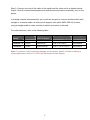
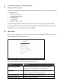
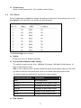
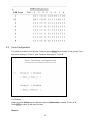
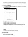
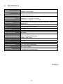
1
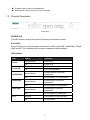
User’s Manual Gigabit Smart Switch Model No.: SP698A http://www.micronet.info Table of Content ------------------------------------------------------------------------------------------------------------------------- 1. Introduction ...............................................................................2 1.1 1.2 1.3 2. Installation .................................................................................4 2.1 2.2 2.3 2.4 3. Preparing the Site.............................................................................. 4 Settling the Switch............................................................................. 4 Connecting to Power......................................................................... 4 Connecting to Network...................................................................... 4 Console Interface Configuration................................................6 3.1 3.2 3.3 3.4 3.5 3.6 3.7 3.8 4. Package Contents ............................................................................. 2 Features ............................................................................................ 2 Physical Description.......................................................................... 3 Setting UP Connection ...................................................................... 6 Main Menu......................................................................................... 6 System Configuration........................................................................ 7 Port Status......................................................................................... 8 VLAN Configuration .......................................................................... 9 Trunk Configuration......................................................................... 10 Port Mirror Configuration................................................................. 11 Reset and Save............................................................................... 11 Specifications ..........................................................................13 1 1. Introduction This switch provides 8 Gigabit Ethernet ports to offer an economical way for small to medium business users to benefit from the increased bandwidth. It upgrades your network to Gigabit connections has never been cost-effective. Also, it is perfect for graphics, multimedia, and other applications that have to move large files across the network quickly. The built-in powerful smart capabilities, such as VLAN, port-trunking, port mirror, empower system administrator to monitor and control the network easily. With its intelligent addressing engine, it provides users with a wire-speed filtering and forwarding of the traffic. All ports support auto-uplink detection, so users don't have to worry about the cable type. Each port will automatically communicate for best speed and to run in half- or full-duplex mode. 1.1 Package Contents Verify your package contains the following items: Gigabit Smart Switch Quick installation guide Manual disk RS-232 cable Rack-mount brackets Rubber foot and screws Power cord 1.2 Features Micronet SP698A provides the following features: Compliant with IEEE802.3 10Base-T, IEEE802.3u 100Base-TX/FX, and IEEE802.3x flow control standards Support auto-negotiation function to automatically select optimal speed (10/100/1000M) and mode (full/half duplex) Support 802.3x flow control for full-duplex mode and back-pressure flow control for half-duplex mode Support 8 groups of port-based VLAN Support 2 groups of port-trunking Support jumbo frame up to 12K Support 4K MAC address entries Support 128K bytes memory buffer Support auto uplink, no more cross-over cable Forward and filter packets at non-blocking, full wire speed 2 Support console port for management Standard 19" rack-mount size, one-unit-height 1.3 Physical Description Front view POWER LED This LED comes on when the switch is properly connected to power. Port LEDs Every RJ-45 port on the front panel relevant four LEDs (10M LINK, 100M LINK, 1000M LINK and ACT) for indicating the connection speed and activity status. LEDs Status LED Power Trunk A/B 1000M LINK Status Operation Steady Green Power is on Off Power is off Steady Green Trunk mode enable Off Steady Green Off 100M LINK Steady Green Off 10M LINK ACT Steady Green Trunk mode disable 1000M network connection established No connection in 1000M speed 100M network connection established No connection in 100M speed 10M network connection established Off No connection in 10M speed Blinking Transmitting or receiving data Off No connection 3 2. Installation 2.1 Preparing the Site Select the site that meets the following requirements: Characteristic 2.2 Requirement Temperature 32 to 122˚F (0 to 50˚C) Humidity 10% ~ 90%, non-condensing Settling the Switch Mounted to 19-inch standard rack Locate the accessories provided in the product package. Use the rack-mount brackets and screws to install the switch into any EIA 19” standard rack. Step 1: Attach the brackets to each side of the chassis. Step 2: Apply the screws to each side and secure them tightly. Step 3: Carefully position the switch into the rack. Step 4: Align the brackets to the side holes on the rack and use rack screws to secure the chassis with the rack. Desktop or any flat surface The switch can sit on desktop or any flat surface with adequate space and ventilation. If you want to place it onto a shelf, make sure the shelf can withstand the weight of the switch. Step 1: Simply put the switch on the desired place. Step 2: Ensure the switch receives good ventilation. Step 3: Proceed to the “Connecting to Power” section. 2.3 Connecting to Power Locate the provided AC power cord. Step 1: Connect the AC power cord to the receptacle at the back of the switch. Step 2: Attach the plug into a standard AC outlet with a voltage ranging from 100 to 240 VAC. Step 3: The power LED on the front panel will come on then. 2.4 Connecting to Network Step 1: First, ensure the power of the switch (and end devices) is turned off. L It may cause electric shock or any possible harm to you if the power is not switched off. Step 2: Prepare cable with corresponding connectors for each type of port in use. 4 Step 3: Connect one end of the cable to the switch and the other end to a desired device. Step 4: Once the connections between two end-devices are made successfully, turn on the power. In making a switch interconnection, you could use any port to connect another switch with straight or crossover cable. As all the ports support auto-uplink (MDI / MDI-X) function, using a straight cable to make a switch-to-switch connection is allowed. For cable selection, refer to the following table: Network Speed Connector Port Speed Half/Full Duplex Cable Type Max. Length 10Base-T RJ-45 10/20 M Cat. 3, 4, 5 UTP/STP 100 meters 100Base-TX RJ-45 100/200 M 1000Base-T RJ-45 1000/2000 M Cat. 5 UTP/STP Cat. 5, 5e UTP/STP 100 meters 100 meters Note: To prevent costly equipment damage and downtime, please consider installing a surge suppression device or a UPS (Un-interrupted Power Supply). 5 3. Console Interface Configuration 3.1 Setting UP Connection Users can configure the switch in command line via console port. The operating mode of the console port is y 9600 (Fix baud rate) y n (No parity checking) y 8 (8 Data bits) y 1 (1 stop bit) y None (No flow control) After attaching a RS-232 cable to the serial port of a PC running a terminal emulation program, press “Enter” key then login screen appears. Enter your password to login the configuration UI. The default password is “admin”. 3.2 Main Menu After key in the password, the main page will show as below. By default, all ports are set at auto-negotiation and flow control on. This switch provides the following management function: Function Statement System Configuration Provides Password, Aging time, Maximum broadcast, Hash Algorithm and Jumbo packet configuration. Port Status Provides ports configuration, including enable/ disable ports, set-up duplex mode and flow control VLAN Configuration Supports up to 8 groups port-base VLAN Trunking Configuration Supports 2 port-trunk groups 6 Port Mirror Configuration Configure source port and target port for mirroring. Reset and Save Save the configured values or reset the switch. Exit Exit the management program. <TAB> Next Item Move to the next item. <ESC> Back Return to previous hierarch or screen. <Enter> Confirm Access a specific function or confirm the values that changed. 3.3 <Space Bar> Select Change or adjust the values for a specific function. ↑ Move to items ↓ ← → System Configuration After pressing enter on the system configuration on the main menu, the screen will show as below: The [System Configuration] Menu includes: z Password Setting: Allow users to change the password. z Aging Time (Sec): Aging time of Mac address entry. The switch provides 3 aging time modes: 300secs, 360secs and aging time disable. z Maximum Broadcast: Maximum broadcast configuration. You can select 32, 48, 64 or disable for maximum broadcast. z Hash Algorithm: Select XOR or Linear mode for Hash Algorithm. 7 z Jumbo Packet: Select Jumbo Packet for 9K, 12K or disable Jumbo Packet. 3.4 Port Status Ports Configuration is applied to change the setting of each port. After pressing enter on the port status on the main menu, the screen will show as below: The [Port Config] menu includes: z Admin: Enable a port (On) or disable a port(Off). z Port speed and duplex mode setting: The modes for each port are: Auto, 1000Mbps Full duplex, 100 Mbps Full/Half duplex, 10 Mbps Full/Half duplex mode. Note: If user configures it as a specific speed and duplex mode please make sure the other port that the switch communicate with is also on the same speed and duplex mode. The following table summarized the function the media supports. Communication Mode Description Auto Auto-Negotiation 1000full 1000Mbps at full duplex mode 100full 100Mbps at full duplex mode 100half 100Mbps at half duplex mode 10full 10Mbps at full duplex mode 10half 10Mbps at half duplex mode z Flow control: 8 There are two modes to choose in flow control, including Enable and Disable. If flow control is set Enable, both parties can send PAUSE frame to the transmitting device(s) if the receiving port is too busy to handle. When it is set Disable, there will be no flow control in the port. It drops the packet if too much to handle. Default: Enable. 3.5 VLAN Configuration This 8-port Gigabit Smart Switch provides 8 port-base VLAN groups and each VLAN groups could comprise 1-8 port. You can select some ports into the same VLAN group by symbol “*”. If the packets come into one port, which only belongs to one VLAN group, the packets just can be forwarded to other ports of this VLAN group. The VLAN setting: follow these steps to assign VLAN groups. y Move the [↑ ↓] to VLAN Group 1 ~ 8 column y Press [ENTER] to the desires group y Press [← →] to the desires port y Press [SPACE] to select and mark*to the desired port y Press [ENTER] to apply the setting For example: We set port-1, 3, 5, 6, 8 as VLAN1 and port-1, 3, 7 as VLAN2. When one packet comes from port-1 or port-3, the packet could be forward to VLAN 1 and VLAN 2. It means only port-1, 3, 5, 6, 8 (VLAN1) and port-1, 3, 7 (VLAN2) will receive the packet. But when packet comes from port-8, only port-1, 3, 5, 6, 8 (VLAN1) will receive the packet. On the other hand, if one packet comes from port-2, only port-4 will receive this packet. 9 3.6 Trunk Configuration This switch provides 2 trunk groups. Simply by press [Enter] key to enable Trunk groups. Port-1 and port-2 belong to “Trunk A”, port-7 and port-8 belongs to “Trunk B”. For Example: Simply by press [Enter] key to enter the mode and [Space Bar] to enable Trunk A or B Press [ESC] to return to the previous item Remark: 10 Mirror and Trunk functions cannot be enabled simultaneously. For example, when you activate Port 1 Trunking Function, you cannot use Port1 for as Mirror port, neither source nor target port. 3.7 Port Mirror Configuration The Smart Switch provides Mirror Configuration to snoop a specified port. Setup a monitored port and monitored mode. For Example: Press [Enter] to enable the port mirroring, Press [Tab] then [Enter] key to select the source port Press [Tab] then [Enter] key to select the Target port Press [ESC] to return to the previous item and continue, or save the configuration on save menu. If port-1 is “Source port” and port-8 is “Target Port”, all the packets come into port-1 will be duplicated to port-8 where snooping PC allocates. Then system administrator could analyze the packets with management tools. Remark: Mirror and Trunk functions cannot be enabled simultaneously. 3.8 Reset and Save z Save current change to EEPROM: 11 To save your settings and disconnect the connectivity simultaneously, use [Tab] to select and press [Enter] to activate. Note: Please note that you should save the changes after doing any configuration for the switch. The parameters will be ignored if you restart the switch without saving. z Reset to Factory Default: To restore all values to back to the factory default, use [Tab] to select and press [Enter] to activate. 12 4. Specifications Standard Interface IEEE802.3, IEEE802.3u, IEEE802.3ab IEEE802.3x flow control 8 * RJ-45 ports (10/100/1000M) 1 * RS-232 console port 10BASE-T: Category 3, 4, 5 UTP/STP Cable Connections 100BASE-TX: Category 5 UTP/STP 1000BASE-T: Category 5, 5e UTP/STP Network Speed 10/100/1000M & full/half duplex mode auto detection (1000M for full duplex only) Feature VLAN, port trunk, port mirror Uplink Auto-uplink (Auto MDI / MDI-X) Switch Fabric 16.0Gbps Buffer Memory 128K bytes MAC Address Table 4K entries 10M: 14,880pps/14,880pps Filtering/Forwarding Rate 100M: 148,800pps/148,800pps 1000M: 1,488,100pps Jumbo Frame 12K bytes Emission FCC, CE Operating Temperature 0 - 50 C (32 - 122 F) Operating Humidity 10% - 90% (Non-condensing) Dimension 441 x 130 x 44 mm Power Supply o o o o 100 ~ 240V AC 50/60Hz Full range internal power supply 2005/04/27 13