1
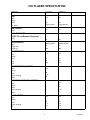
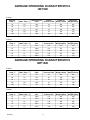
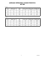
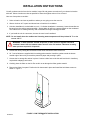
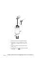
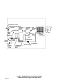
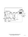
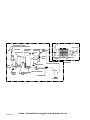
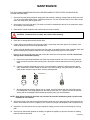
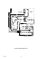
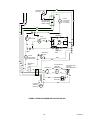
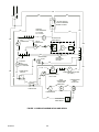
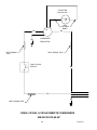
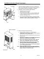
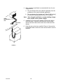
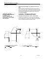
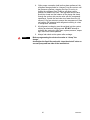
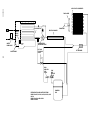
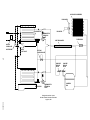
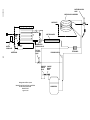
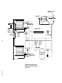
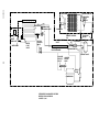
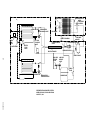
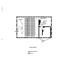
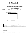
THE HOTTEST MACHINES ON ICEt Installation/Maintenance Instructions “I” Series Flaked/Nugget Ice Machines Model Number Description IAF1000 & 650 Flaker/Nugget Modular Head Ice Maker Air Cooled IWF1000 & 650 Flaker/Nugget Modular Head Ice Maker Water Cooled IRF1000 & 650 Flaker/Nugget Modular Head Ice Maker Remote Cooled Part No. 630460003 1/10/97 Revised 4/11/97 THIS DOCUMENT CONTAINS IMPORTANT INFORMATION This Manual must be read and understood before installing or operating this equipment IMI CORNELIUS INC; January 1997 PRINTED IN U.S.A TABLE OF CONTENTS Page INTRODUCTION . . . . . . . . . . . . . . . . . . . . . . . . . . . . . . . . . . . . . . . . . . . . . . . . . . . . . . . . . . . 1 ICE FLAKER SPECIFICATION . . . . . . . . . . . . . . . . . . . . . . . . . . . . . . . . . . . . . . . . . . . . . . 2 ICE FLAKER SPECIFICATION . . . . . . . . . . . . . . . . . . . . . . . . . . . . . . . . . . . . . . . . . . . . . . 3 AVERAGE OPERATING CHARACTERISTICS IAF1000 . . . . . . . . . . . . . . . . . . . . . . . . . . . . . . . . . . . . . . . . . . . . . . . . . . . . . . . . . . . . . . 4 AVERAGE OPERATING CHARACTERISTICS IWF1000 . . . . . . . . . . . . . . . . . . . . . . . . . . . . . . . . . . . . . . . . . . . . . . . . . . . . . . . . . . . . . . 4 AVERAGE OPERATING CHARACTERISTICS IRF1000 . . . . . . . . . . . . . . . . . . . . . . . . . . . . . . . . . . . . . . . . . . . . . . . . . . . . . . . . . . . . . . 5 INSTALLATION INSTRUCTIONS . . . . . . . . . . . . . . . . . . . . . . . . . . . . . . . . . . . . . . . . . . . . 6 WATER AND ICE CIRCUIT . . . . . . . . . . . . . . . . . . . . . . . . . . . . . . . . . . . . . . . . . . . . . 9 ELECTRICAL CIRCUIT . . . . . . . . . . . . . . . . . . . . . . . . . . . . . . . . . . . . . . . . . . . . . . . . . 10 CIRCUIT DESCRIPTION . . . . . . . . . . . . . . . . . . . . . . . . . . . . . . . . . . . . . . . . . . COMPONENT DESCRIPTION . . . . . . . . . . . . . . . . . . . . . . . . . . . . . . . . . . . . . . . . . . BIN THERMOSTAT . . . . . . . . . . . . . . . . . . . . . . . . . . . . . . . . . . . . . . . . . . . . . . . 10 10 10 GEARMOTOR START RELAY . . . . . . . . . . . . . . . . . . . . . . . . . . . . . . . . . . . . . 10 COMPRESSOR CONTACTOR . . . . . . . . . . . . . . . . . . . . . . . . . . . . . . . . . . . . . 10 GEARMOTOR DELAY THERMOSTAT . . . . . . . . . . . . . . . . . . . . . . . . . . . . . . 10 ON–OFF SWITCH / CIRCUIT BREAKER . . . . . . . . . . . . . . . . . . . . . . . . . . . . 10 FAN CYCLING SWITCH (R404A UNITS) . . . . . . . . . . . . . . . . . . . . . . . . . . . . 11 HIGH PRESSURE CONTROL . . . . . . . . . . . . . . . . . . . . . . . . . . . . . . . . . . . . . . 11 COMPRESSOR START RELAY . . . . . . . . . . . . . . . . . . . . . . . . . . . . . . . . . . . . 11 POTENTIAL RELAYS . . . . . . . . . . . . . . . . . . . . . . . . . . . . . . . . . . . . . . . . . . . . . 11 CAPACITORS – GENERAL . . . . . . . . . . . . . . . . . . . . . . . . . . . . . . . . . . . . . . . . 11 DUMP SWITCH . . . . . . . . . . . . . . . . . . . . . . . . . . . . . . . . . . . . . . . . . . . . . . . . . . 11 MAINTENANCE . . . . . . . . . . . . . . . . . . . . . . . . . . . . . . . . . . . . . . . . . . . . . . . . . . . . . . . . . . . 15 “I” SERIES FLAKER CLEANING AND SANITIZING PROCEDURE . . . . . . . . . . . . . . . . . . . . . . . . . . . . . . . . . . . . . . . . . . . . 16 WATER TREATMENT . . . . . . . . . . . . . . . . . . . . . . . . . . . . . . . . . . . . . . . . . . . . . . . . . . 17 WINTER STORAGE . . . . . . . . . . . . . . . . . . . . . . . . . . . . . . . . . . . . . . . . . . . . . . . . . . . 17 CLEANING THE CONDENSER (AIR COOLED) . . . . . . . . . . . . . . . . . . . . . . . . . . . 17 TROUBLESHOOTING . . . . . . . . . . . . . . . . . . . . . . . . . . . . . . . . . . . . . . . . . . . . . . . . . . 21 i 6304600003 FIGURE AND ILLUSTRATIONS FIGURE 1. BIN THERMOSTAT INSTALLATION . . . . . . . . . . . . . . . . . . . . . . . . . . . 6 FIGURE 2. SERVICE CONNECTIONS . . . . . . . . . . . . . . . . . . . . . . . . . . . . . . . . . . . 7 FIGURE 3. INSTRUCTIONS FOR CONVERTING FLAKED ICE TO NUGGET ICE. . . . . . . . . . . . . . . . . . . . . . . . . . . . . . . . . . . . . . . . . . 8 FIGURE 4. WATER LEVEL . . . . . . . . . . . . . . . . . . . . . . . . . . . . . . . . . . . . . . . . . . . . . . 9 FIGURE 5. REFRIGERATION AND WATER SYSTEMS MODELS IAF1000, IAF650, IAF450 AND IAF200 . . . . . . . . . . . . . . . . . . . . . . . . . . 12 FIGURE 6. REFRIGERATION AND WATER SYSTEMS MODELS IWF1000, IWF650 AND IWF450 . . . . . . . . . . . . . . . . . . . . . . . . . . . . . . . . 13 FIGURE 7. REFRIGERATION AND WATER SYSTEM MODELS IRF1000 . . . . . 14 FIGURE 8. WIRING DIAGRAM IAF1000 . . . . . . . . . . . . . . . . . . . . . . . . . . . . . . . . . . 18 FIGURE 9. WIRING DIAGRAM IWF1000 AND IRF1000 . . . . . . . . . . . . . . . . . . . . 19 FIGURE 10. WIRING DIAGRAM IAF650 AND IWF650 . . . . . . . . . . . . . . . . . . . . . . 20 6304600003 ii INTRODUCTION We have strived to produce a quality product. The design has been kept simple thus insuring trouble–free operation. This manual has been prepared to assist the Installer. If you encounter a problem which is not covered in this manual, please feel free to write or call. We will be happy to assist you in any way we can. When writing, please state the model and serial number of the machine. Address all correspondence to: A Product of IMI Cornelius Inc. One Cornelius Place Anoka, MN 55303–1592 Phone 800–554–3526 FAX 612–422–3232 PRINTED IN USA 1 630460003 ICE FLAKER SPECIFICATION MODEL IAF1000 IWF1000 IRF1000 230 1 60 2 plus ground 230 1 60 2 plus ground 230 1 60 2 plus ground 20 20 20 25 25 25 R404a (HP62) 30 851 R404a (HP62) 25 709 R404a (HP62) 170 4820 230 1 60 61 12.5 230 1 60 61 12.5 230 1 60 61 12.5 230 1 60 0.36 6 230 1 60 0.36 6 230 1 60 0.95 1/8 230 1 60 0.95 1/8 UNIT Volts Phase Hertz No. Wires MIN. CIRCUIT Amps MAX. FUSE SIZE (HVAC Circuit Breaker Required) Amps REFRIGERANT Type Weight (oz.) Weight (g) COMPRESSOR Volts Phase Hertz LRA RLA CONDENSER FAN MOTOR Volts Phase Hertz Amps, Running Watts 230 1 60 1.09 75 AIR CIRCULATION FAN MOTOR Volts Phase Hertz Amps, Running Watts GEAR MOTOR Volts Phase Hertz Amps, Running HP 630460003 230 1 60 0.95 1/8 2 ICE FLAKER SPECIFICATION MODEL IAF650 IWF650 115 1 60 2 plus ground 115 1 60 2 plus ground 20 20 20 20 R404a (HP62) 25 709 R404a (HP62) 17 482 115 1 60 59 11.6 115 1 60 59 11.6 UNIT Volts Phase Hertz No. Wires MIN. CIRCUIT Amps MAX. FUSE SIZE (HVAC Circuit Breaker Required) Amps REFRIGERANT Type Weight (oz.) Weight (g) COMPRESSOR Volts Phase Hertz LRA RLA CONDENSER FAN MOTOR 115 1 60 1.75 50 Volts Phase Hertz Amps, Running Watts AIR CIRCULATION FAN MOTOR 115 1 60 0.36 6 Volts Phase Hertz Amps, Running Watts GEAR MOTOR 115 1 60 1.9 1/8 Volts Phase Hertz Amps, Running HP 3 115 1 60 1.9 1/8 630460003 AVERAGE OPERATING CHARACTERISTICS IAF1000 IP Units Ambient Temp _F Water Temp _F Head Pressure PSIG Suction Pressure PSIG Flaked Ice Weight Lb/Day Nugget Ice Weight Lb/Day 70 50 234 19 883 921 80 70 216 19 786 805 90 70 247 21 761 794 90 80 247 21 720 747 105 70 300 24 664 687 Ambient Temp _C Water Temp _C Head Pressure kPa Suction Pressure kPa Flaked Ice Weight kg/Day Nugget Ice Weight kg/Day 21 10 1613 131 401 418 27 21 1489 313 357 365 32 21 1703 145 345 360 32 27 1703 145 327 339 41 21 2068 165 301 312 SI Units AVERAGE OPERATING CHARACTERISTICS IWF1000 IP Units Ambient Temp _F Water Temp _F Head Pressure PSIG Suction Pressure PSIG Flaked Ice Weight Lb/Day Nugget Ice Weight Lb/Day 70 50 271 19 932 935 80 70 277 20 794 806 90 70 277 20 792 798 90 80 280 21 733 744 105 70 277 20 785 789 Ambient Temp _C Water Temp _C Head Pressure kPa Suction Pressure kPa Flaked Ice Weight kg/Day Nugget Ice Weight kg/Day 21 10 1868 131 423 424 27 21 1910 138 360 366 32 21 1910 138 359 362 32 27 1931 145 332 337 41 21 1910 138 356 358 SI Units 630460003 4 AVERAGE OPERATING CHARACTERISTICS IRF1000 IP Units Ambient Temp _F Water Temp _F Head Pressure PSIG Suction Pressure PSIG Flaked Ice Weight Lb/Day Nugget Ice Weight Lb/Day 70 50 234 19 883 921 80 70 216 19 786 805 90 70 247 21 761 794 90 80 247 21 720 747 105 70 300 24 664 687 Ambient Temp _C Water Temp _C Head Pressure kPa Suction Pressure kPa Flaked Ice Weight kg/Day Nugget Ice Weight kg/Day 21 10 1613 131 401 418 27 21 1489 131 357 365 32 21 1703 145 345 360 32 27 1703 145 327 339 41 21 2068 165 301 312 SI Units 5 630460003 INSTALLATION INSTRUCTIONS You will get better service from the ice machine, longer life and greater convenience if you choose its location with care. Select a location as close as possible to where the highest volume of ice will used. Here are a few points to consider: 1. Select a location as close as possible to where you are going to use the most ice. 2. Allow a minimum of 6” space at sides and rear of machine for ventilation. 3. A kitchen installation is not desirable as a rule. If a kitchen installation is necessary, locate the machine as far away from the cooking area as possible. Grease laden air will form a greasy deposit on the condenser. This reduces the ice making efficiency and necessitates thorough cleaning quite often. 4. If you install the unit in a storeroom, be sure the room is well ventilated. NOTE: Do not install where the ambient and incoming water temperature will drop below 50° F or rise to over 100° F. WARNING: If water pressure exceeds 50 pounds, a water pressure regulator should be installed in water inlet line between water shut–off valve and strainer. Minimum incoming water pressure required is 22 pounds. 5. Uncrate the unit by cutting the lower band on the carton and lift the carton off the unit. 6. All “I” series flakers are supplied with bin sealing gasket material. Install the gasket around the bottom outside edge of the unit by removed the protective paper and pressing in place. 7. Uncrate the ice storage bin and set in place. Connect a drain hose to the bin and level the bin. Install any required bin adapter(s) at this time. 8. Carefully place the flaker on the bin. Be careful not to damage the flaker gasket material. 9. Remove the flaker front panel. Position the bin thermostat in place and install the hold down screws as shown in Figure 1. 630460003 FIGURE 1. BIN THERMOSTAT INSTALLATION 6 10. The incoming water for the ice making section requires a 3/8” copper tube. Connect this water tube to the 3/8” male flare fitting on the back of the unit. Make all drain connections. Drain tubes cannot be teed together. See Figure 2 for location of all plumbing connections. NOTE: For water cooled units, a separate 3/8” copper water line is required to be connected to the flare fitting on the back of the unit marked condenser water in. A 3/8” flare connected line will have to be provided from the fitting marked condenser water out to the drain. A water regulating valve installed at the factory was set to maintain 290 to 310 PSI head pressure for R–404a units. After 10 minutes of operation check the water temperature at condenser outlet and adjust to 100_F, 105_F if necessary. 11. Connect a drain hose to the condensate drain stub tube. ill371 NOTE: All plumbing must be done in accordance with national and local codes. ELECTRICAL SERVICE OPENING(7/8-IN. DIA. HOLE) 22.00 5.25 1.25 POTABLE WATER INLET (3/8-IN. MALE FLARE) 22.60 27.83 5.25 CONDENSER DRAIN 4.50 FRONT SIDE ICE DROP OPENING BOTTOM VIEW DUMP VALVE DRAIN HOSE (9/16-IN. I.D. BY 3/4-IN. O.D.) IAF 650 ELECTRICAL SERVICE OPENING(7/8-IN. DIA. HOLE) 30.00 10.31 5.25 REAR VIEW GEABOX/WTRPN DRAIN HOSE (9/16-IN. I.D. BY 3/4-IN. O.D.) POTABLE WATER INLET (3/8-IN. MALE FLARE) 22.63 27.83 5.25 CONDENSER DRAIN 5.20 FRONT SIDE BOTTOM VIEW ICE DROP OPENING DUMP VALVE DRAIN HOSE (9/16-IN. I.D. BY 3/4-IN. O.D.) IAF 1000 REAR VIEW GEABOX/WTRPN DRAIN HOSE (9/16-IN. I.D. BY 3/4-IN. O.D.) FIGURE 2. SERVICE CONNECTIONS 12. Bring the electrical supply (20 Amp.) into the unit at the rear of the cabinet and enters the unit control box. The power and ground connections are completed to the leads in the control box. Strain relief connections must be made at the cabinet and at the control box. NOTE: Make sure the proper voltage and number of wires are provided. See serial plate for proper configuration. NOTE: All wiring must conform to national and local codes. 7 630460003 1 2 3 4 5 1. Remove the chute from the evaporator assembly 2. Remove item 1, .50-20 x 1.25 bolt; item 2, .50 lockwasher; item 3, ice paddle, and item 4, flaker cutter head. 3. Install item 5, nugget ice cutter head, and re-install items 1, 2, & 3 4. Re-install chute. (RTV must be used around the base of the chute.) 630460003 FIGURE 3. INSTRUCTIONS FOR CONVERTING FLAKED ICE TO NUGGET ICE. 8 WATER AND ICE CIRCUIT The supply water enters the float chamber through a small orifice. The water level rises and lifts the float arm on the float valve and seats the valve, shutting off the water supply when the water is at the desired level. As the water leaves the float chamber, filling the evaporator, the float drops and allows additional water to enter refilling the float chamber. Thus the water level is maintained automatically as the unit operates. The water level in the evaporator shell will rise to the same level as the water in the float chamber. The water in direct contact with the evaporator wall freezes and forms ice on the evaporator wall. As the freezing continues the ice becomes thicker and exceeds the space between the evaporator wall and the auger. The auger rotating at 8 RPM then chips off the ice and moves it to the surface of the shell. When the ice reaches the top surface of the water in the shell it is pushed upward through the extruder opening into the cutter heads. From the cutter head the ice enters the drop chute and falls into the storage bin. This action continues until the ice comes in contact with the bin thermostat and the unit is shut down. The unit will remain off until the ice drops from the bin thermostat through consumption or melting, at which time the unit will restart. Water Inlet Fitting Water Pressure Switch Strainer Water Level Float Valve Evaporator Gear Motor Water Dump Valve FIGURE 4. WATER LEVEL 9 630460003 ELECTRICAL CIRCUIT CIRCUIT DESCRIPTION As the manual on-off-circuit breaker switch is pushed to ”on”, an electrical circuit is completed to the gearmotor via the circuit breaker gearmotor overload, power relay / contactor, gearmotor delay thermostat and the bin thermostat. After the previous circuit has been completed the fan motor will start when the head pressure reaches 270 PSI and will cycle off at 205 PSI. The compressor will start via the high pressure control and the compressor starting relay. COMPONENT DESCRIPTION BIN THERMOSTAT This is electrically in ”series” with the ice making system. when the bin is full, the contact opens, terminating power to the machine. CAUTION: Setting the bin thermostat to the coldest position may cause excessive ice build-up in the chute and it can possibly cause the chute to pop-off from ice build-up. GEARMOTOR START RELAY This is a current type relay which means as the gearmotor run winding comes ”on” the line, the current draw initially is relatively heavy through the relay coil (coil is in series with run winding). It then acts like a normal relay and the N.O. start contact ”makes”, completing a circuit through the start capacitor to the start winding. As the gearmotor picks up speed, the amp draw through the relay coil drops off allowing the armature to return to its normal position (start contact ”opens”). This action removes the start winding from the circuit. COMPRESSOR CONTACTOR Controls the compressor input power only. GEARMOTOR DELAY THERMOSTAT The purpose of the Delay Thermostat is to allow an electrical path to the gearmotor for continuous operation to clear the evaporator of ice to prevent auger freeze up. As the ice from the evaporator is augered up, the suction line of the evaporator will warm-up causing the Delay Thermostat to open, cancelling the gearmotor electrical circuit. CAUTION: The Delay Thermostat must be insulated to prevent biasing action of room and compressor area temperatures. This thermostat keeps the gearmotor running until the suction line temperature reaches 45_ F after the bin thermostat terminates power to the contactor. ON–OFF SWITCH / CIRCUIT BREAKER This switch interrupts power to the entire unit. The switch has a circuit breaker incorporated into its’ design. This circuit breaker will trip out in the event the gearmotor draws to high of amps In such an event the power is interrupted to the unit. To reset the circuit breaker and reestablish power to the unit, push the switch to the ”off” position and then back to the ”on” position. 630460003 10 FAN CYCLING SWITCH (R404a Units) The function of this switch is to maintain condensing pressures at a satisfactory level during–low ambient conditions. The switch breaks the circuit to the condenser fan motor at 205 PSI and makes the circuit at 275 PSI. HIGH PRESSURE CONTROL The high pressure cut out is electrically in series with the contactor. As the head pressure rises to 450 PSIG, for R404a charged units, a preset level the contact opens thus breaking the circuit to the compressor via the contactor. This control must be reset manually on R404a units. COMPRESSOR START RELAY This is a current type relay and contains a N.O. contact which is connected in series with the start winding of the compressor. The relay coil is electrically in series with the run winding. When power is applied, the compressor draws high current which sets up a magnetic field around the magnet coil which causes the relay to operate, closing the relay contact. As the compressor approaches operating speed, the current flowing through the coil decreases, permitting the relay contact to open, thereby opening the starting circuit. POTENTIAL RELAYS The potential relay is used as a compressor starting relay, The contact in the potential relay is N.C.. The magnet coil is connected across (parallel) the start winding and is affected by induced voltage, generated by the start winding. As the compressor comes up to design speed, the voltage across the relay coil increases and at running speed is sometimes as much as 2 1/2 times the supply voltage. This voltage sets up a magnetic field which causes the relay to operate. The starting relay is calibrated to remove the start capacitor (open the starting circuit) at approximately 80% of the compressor operating speed. NOTE: BOTH TYPES OF RELAYS ARE DESIGNED TO OPERATE WITHIN VERY NARROW LIMITS OF VOLTAGE AND CURRENT DICTATED BY MOTOR DESIGN, THEREFORE, WHEN MAKING A REPLACEMENT OF A RELAY ALWAYS PROVIDE AN EXACT REPLACEMENT RECOMMENDED BY THE COMPRESSOR MANUFACTURER. CAPACITORS – GENERAL An electrical capacitor is a device which stores up electrical energy. Capacitors are used with single phase motors to provide starting torque and improve running characteristics; by feeding this energy to the start winding in step with the run winding. Any capacitor has three (3) essential parts, two (2) of which are usually foil plates separated and insulated by the third part called the dielectric. Two general types of capacitors are used with electric motors. The electrolytic starting capacitor usually uses a very thin film of oxide on the metallic plate as the dielectric. The running capacitor usually is of the liquid filled type. and remains in the circuit during both the start and run operation. DUMP SWITCH This switch activates the evaporator dump valve manually. This allows the draining of the evaporator for service or cleaning. Dumping the water every 24 or 48 hours will reduce the down time for cleaning in high mineral content water areas. 11 630460003 WATER INLET FITTING WATER PRESSURE SWITCH HIGH SIDE SERVICE VALVE STRAINER FAN MOTOR LOW SIDE SERVICE VALVE HIGH PRESSURE SWITCH EVAPORATOR FAN FAN CYCLE SWITCH FLOAT VALVE AIR COOLED CONDENSER COMPRESSOR GEAR MOTOR FILTER/DRYER WATER DUMP VALVE 630460003 THERMOSTATIC EXPANSION VALVE HEAT EXCHANGER FIGURE 5. REFRIGERATION AND WATER SYSTEMS MODELS IAF1000, IAF650, IAF450 AND IAF200 12 WATER REGULATING VALVE WATER INLET FITTING WATER PRESSURE SWITCH STRAINER HIGH SIDE SERVICE VALVE LOW SIDE SERVICE VALVE HIGH PRESSURE SWITCH EVAPORATOR DRAIN WATER INLET FLOAT VALVE WATER COOLED CONDENSER COMPRESSOR GEAR MOTOR FILTER/DRYER WATER DUMP VALVE THERMOSTATIC EXPANSION VALVE HEAT EXCHANGER FIGURE 6. REFRIGERATION AND WATER SYSTEMS MODELS IWF1000, IWF650 AND IWF450 13 630460003 FAN CYCLE SWITCH WATER INLET FITTING WATER PRESSURE SWITCH STRAINER EVAPORATOR HIGH SIDE SERVICEVALVE FAN MOTOR LOW SIDE SERVICE VALVE HIGH PRESSURE SWITCH FAN CHECK VALVE FLOAT VALVE HEAD PRESSURE CONTROL CONDENSER COIL REMOTE CONDENSER COMPRESSOR S GEAR MOTOR LIQUID SOLENOID VALVE WATER DUMP VALVE THERMOSTATIC EXPANSION VALVE HEAT EXCHANGER FILTER/DRYER RECEIVER 630460003 FIGURE 7. REFRIGERATION AND WATER SYSTEM MODELS IRF1000 14 MAINTENANCE THE FOLLOWING MAINTENANCE SHOULD BE PERFORMED AT LEAST EVERY SIX MONTHS ON FLAKED ICE MACHINES: 1. Check the incoming electrical power supply while the machine is starting. Voltage must not drop lower than –5% of the rated name plate voltage. Conditions below the –5% limit will reduce the life of the start components, the compressor and the gear motor. 2. Check water level in the float tank. The water level must be maintained at the top of the evaporator. adjust as necessary. (see illustration.) 3. Clean the air–cooled condenser with a stiff brush and vacuum cleaner. CAUTION: Condenser fins are sharp. Use caution when cleaning. 4. Clean the ice storage bin and flush the bin drain. 5. If water filter(s) are installed in the inlet water supply, check these filters and replace as necessary. Also clean the strainer screen at the float chamber inlet. 6. If heavy mineral deposits (scale) are present on the auger or the inside surface of the evaporator clean and sanitize following the procedure outlined in the Cleaning and Sanitizing section is this manual. 7. Remove the ice chute hold-down nuts and remove the chute from the evaporator shell. Be careful not to damage the bin thermostat capillary. A. Remove the cutter head hold down bolt. Mark the extruder head at one of it’s 3 mounting bolts and remove all three extruder head mounting bolts. Grasp the extruder head and remove it by pulling upward. B. Check the extruder head bearing for wear or scoring patterns. Should the bearing surface appear okay, reinstall the extruder. Rotate the extruder 120_ when installing, using the reference mark you made on the extruder in step A above. See the drawing below. ROTATE 120_ A C. B C Should the extruder bearing appear worn or scored, check the bearing with the GO-NO-GO gauge P/N 630900056. If the gauge passes into the bearing more than 1/2I, replace the extruder head assembly with an exchanged head and bearing assembly from your local distributor. NOTE: High mineral content in the water may increase the extruder head bearing wear if proper water treatment is not installed. 8. Activate the dump valve switch several times and be certain the valve opens and fully closes with each activation. Should the valve fail to completely close, replace the plunger and diaphram with a replacement kit. 9. Replace the ice chute and check for proper alignment making sure the chute is not blocking the ice flow path. 10. Check the bin thermostat operation by holding ice against the capillary to open the control thus shutting down the machine operation. 15 630460003 “I” SERIES FLAKER CLEANING AND SANITIZING PROCEDURE 1. To eliminate water from entering the reservoir, block up the float located inside the reservoir, activate the dump switch to the “ON” position and turn the power switch to “ON”. Allow the evaporator to drain. Turn the power switch to the “OFF” position. 2. Remove the ice chute by removing the hold-down nuts at the base and the self-clamping bolt at the top. Lift the chute clear of the evaporator assembly. 3. Return the float to it’s normal position. As the float chamber refills with water and fills the evaporator, add 3 oz. of Calgon Nickel-Safe ice machine cleaner to the float chamber. (Gravity will feed the cleaner to the evaporator.) NOTE: Do not remove the auger, extruder head, or other parts from the evaporator assembly. 4. Allow the cleaning solution to stand in the evaporator for 20 - 30 minutes. Block up the float and drain the evaporator as in step 1. 5. Rinse/flush by carefully filling with warm water (100_F) and drain by following step 1 again. Repeat at least 3 times. During the final rinse/flush cycle, add 1 tablespoon of regular Baking Soda and allow it to stand for 10 - 15 minutes. 6. Drain the evaporator and rinse/flush one more time. 7. Install the ice chute and panels. (RTV must be used around the base of the chute.) CAUTION: Should sanitizing be required, DO NOT use a mixture of household bleach and water Chlorine will attack stainless steel. Use only a commercial ice machine sanitizer such as Calgon Sanitizer for ice machines, following the directions on the container. NOTE: When cleaning and/or sanitizing is complete return the machine back to an ice making cycle. Discard the first 30 minutes of ice production. DO NOT allow any ice that has been in contact with sanitizer to ever be used. 630460003 16 WATER TREATMENT During the freezing process, as water passes over the evaporator, the impurities in the water have a tendency to be rejected and the plate will freeze only the pure water. However, the more dissolved solids in the water, the more troublesome the freezing operation will be. Bicarbonates in the water are the most troublesome of the impurities. These impurities will cause scaling on the evaporator, clogging of the float valve mechanism and other parts in the water system. If the concentration of impurities is high, mushy ice may be the result. Parts of the Flaker, that are in contact with the water or ice, may corrode if the water is high in acidity. In some areas, water may have to be treated in order to overcome some of the problems that arise because of the mineral content. IMI Cornelius has water filter/treatment systems available to control impurities found in most water supplies. Contact your local dealer for more information. WINTER STORAGE If the unit is to be stored in an area where the temperature will drop below freezing, it is most important that all water lines be drained to prevent them from freezing and possible rupture. To blow out the water line, disconnect the water supply at the cabinet inlet and use air pressure to force the water into the water reservoir pan, it can then be removed from the water pan. WATER COOLED CONDENSER – To remove water from condenser unhook water supply and attach compressed air hose. Start machine. As head pressure reaches the appropriate level opening the water regulating valve, the compressed air will force the water out. Do not let the machine operate longer than necessary. CLEANING THE CONDENSER (AIR COOLED) In order to produce at full capacity, the refrigeration condenser must be kept clean. The frequency of cleaning will be determined by surrounding condition. A good maintenance plan calls for an inspection at least every two months. With a vacuum cleaner, remove all accumulated dust and lint that has adhered to the finned condenser at the rear of the unit. The use of a stiff bristle brush may be helpful. CAUTION: CONDENSER COOLING FINS ARE SHARP. USE CARE WHEN CLEANING. 17 630460003 BL GW CONTROL LOW PRESSURE C.I. 20 PSIG C.O. 10 PSIG ON-OFF SWITCH CIRCUIT BREAKER RATED 1.5 AMPS RD BK BL RD BL BK BIN THERMOSTAT BL GEAR MOTOR START RELAY DELAY THERMOSTAT BK BK 2 RD RD WATER DUMP VALVE BK BK COMPRESSOR C WATER DUMP SWITCH 2 1 3 R S RD COMPRESSOR RUN CAPACITOR 35MFD 370V WH COMPRESSOR START CAPACITOR 145-174MFD 250V RD YL YL OR BR BK BL COMPRESSOR START RELAY RD BK CONTACTOR BK BK FAN SWITCH CI 275 CO 205 1 5 2 M CONDENSER FAN MOTOR BK RD 208/230 VOLTS 60 Hz FIGURE 8. WIRING DIAGRAM IAF1000 630460003 1 WH RD RD M 4 RD T/D 3 RD CONTROL HIGH PRESSURE C.O. 450 PSIG BL GEAR BK BL BK YL 3 18 RD BK Crankcase Heater (IRF Only) BL BK ON-OFF Switch Circuit Breaker Rated 1.5 Amps GW Control Low Pressure CI 20 PSIG CO 10 PSIG BK RD BK BL RD BL BK Gear Motor Start Relay BL Delay Thermostat Bin Thermostat YL BK M WH BK RD RD RD T/D BK BK BK Cooling Fan Motor BL Water Dump Valve Control High Pressure CO 450 PSIG M WH BK RD RD BK BL RD BK Water Dump Switch 2 1 3 Compressor BL RD BR R C S Compressor Run Capacitor 35MFD 370 V RD RD YL Compressor Start Capacitor 145-174MFD 250 V YL OR RD Contactor BK BK RD Compressor Start Relay RD Liquid Line Solenoid (IRF Only) FIGURE 9. WIRING DIAGRAM IWF1000 AND IRF1000 19 630460003 WH GW WH 22i 12k 11 BK 21 BK WH CONTROL LOW PRESSURE C.I. 20 PSIG C.O. 10 PSIG BK ON–OFF SWITCH CIRCUIT BREAKER RATED 2.0 AMPS BL WH WH BL BL BK BIN THERMOSTAT BL GEAR MOTOR START RELAY DELAY THERMOSTAT YL 3 BK M 4 RD BK BK CONTROL HIGH PRESSURE C.O. 450 PSIG BK M WATER DUMP VALVE BL COOLING FAN MOTOR IWF ONLY WH WH BK WH BL BK BK BL BK WATER DUMP SWITCH 2 1 LOW AMBIENT SWITCH (A/C ONLY) CI275 C0205 3 BR BL R C M BK S COMPRESSOR BK CONDENSOR FAN MOTOR (A/C ONLY) RUN COMPRESSOR CAPACITOR 30MFD 440V RD RD WH CONTACTOR YL COMPRESSOR START CAPACITOR YL OR BR COMPRESSOR START RELAY 1 5 2 FIGURE 10. WIRING DIAGRAM IAF650 AND IWF650 630460003 WH T/D 3 1 BK 2 RD GEAR 20 TROUBLESHOOTING Trouble UNIT WILL NOT RUN COMPRESSOR CYCLES INTERMITTENTLY. MAKING WET ICE. Probable Cause Remedy A. On–off switch in ”off” position. A. Turn switch to ”on”. B. Defective on–off switch. B. Check and replace. C. Blown fuse. C. Replace fuse and check for cause of blown fuse. D. Thermostat set too warm for ambient. D. Adjust colder. E. Contactor contacts corroded. E. Check and clean. F. Defective thermostat. F. Check and replace. G. Loose electrical connection. G. Check wiring. H. Gearmotor overload protector has cut off machine. H. Turn switch to off then to on. A. Low voltage. A. Check Load voltage. B. Dirty condenser. B. Clean condenser. C. Air circulation restricted. C. Remove restriction. D. Defective condenser fan motor. D. Check and replace. E. Defective relay, overload protector or starting capacitor. E. Check and replace. F. Loose electrical connection F. Check wiring. A. Surrounding air temperature too high. A. Correct or move unit B. High water level in float reservoir. B. Lower water level C. Scale on the evaporator C. Clean D. Dirty condenser. D. Clean condenser E. Faulty compressor. E. Check and replace* F. Refrigerant leak. F. Check and repair* *NOTE: Special care must be used with R404a (HP62) charged systems using (POE) Polyolester oil. The refrigeration system must not be open longer than 15 min., and the appropriate drier must be used due to the moisture absorption properties of the POE oil. Also ALCO EKH Series recommended. UNIT RUNS BUT MAKES NO ICE. A. Leak in refrigerant system. A. Check and repair. B. Moisture in system. B. Check, evacuate and replace drier in system. C. No water. C. Check water supply. D. ”O” ring leaking at bottom of evaporator shell mounting support. 21 D. Check and replace ”O” ring. 630460003 Trouble UNIT RUNS BUT MAKES NO ICE. (CONT’D) WATER LEAKS. EXCESSIVE NOISE OR CHATTERING. MACHINE RUNS WITH FULL BIN OF ICE, OR ICE CHUTE IS FORCED OFF THE EVAPORATOR. 630460003 Probable Cause Remedy E. Compressor not running. E. Check wiring, start components, compressor. Repair or replace as required. A. Worn or bad float valve. A. Check and replace. B. Float and arm assembly stuck. B. Check and adjust or replace. C. O-ring leaking at bottom of evaporator shell. C. Check and replace. D. Auger seal assembly. D. Check and replace. E. Storage bin drain and tubing. E. Check and repair. A. Mineral or scale deposits on inside of evaporator shell. A. Clean inside surfaces by filling evaporator shell with ice machine cleaner. B. Intermittent water supply . B. Check inlet water line . C. Water level in float tank too low. C. Check and adjust water level. D. Auger gearmotor end–play or worn bearings. D. Repair or replace. E. Air lock in gravity water supply line from float tank to evaporator shell. E. Check and adjust traps from supply. A. Storage bin thermostat set too cold or defective. A. Check and adjust warmer or replace as required. B. Bin thermostat thermowell out of path of ice. B. Adjust thermowell. 22 Trouble Probable Cause Remedy A. Ice jams up in evaporator shell. A. Clean inside surface of evaporator shell. B. Bin thermostat will not shut–off machine. Set too cold. B. Check and adjust or replace . C. Auger motor has worn bearings. C. Check and replace. D. Ice chute out of alignment, restricted ice flow out of evaporator section. D. Re–align. E. Ice chute restricting ice flow. E. Align or replace ice chute if damaged. F. Incoming water temperature too cold. F. Maintain temperature above 50°F. G. Bin thermostat does not shut–off when bin is full of ice. G. Adjust or replace bin thermostat if necessary. H. Mineral or scale deposits on inside of evaporator shell and evaporator. H. Inspect and clean. I. Low ambient temperature in room where unit is located. I. Maintain temperature above 50°. J. Gearmotor sticking which causes it to draw excessive amperage. J. Check and replace. UNIT GOES OFF OR TRIPS K. CIRCUIT BREAKER. (CONT’D) Plugged expansion valve causing low back pressure. K. Replace the drier-filter, evacuate and recharge the system. L. Refrigerant leak causing low back pressure. L. Find and repair leak. Replace the drier-filter, evacuate and recharge the system M. Auger out of line. M. Check extruder bearing and exchange as needed. N. Broken auger N. Replace auger. O. Low water level in float tank reservoir. O. Adjust float arm to maintain correct water level. P. Gearmotor Delay Thermostat does not keep gearmotor running after Bin Thermostat opens. P. Check operation and / or replace. UNIT OFF OR TRIPS CIRCUIT BREAKER. 23 630460003 “I” Series “Remote” Ice Machine 630460003 24 25 630460003 CAPACITOR 2 mfd 440 VAC RED COLORED BAND M BK GR BK CONDENSER FAN MOTOR HEAT SHRINK TAPE HEAT SHRINK TAPE FAN CYCLING SWITCH BK RD GR HEAT SHRINK TAPE CR800, CR1200, & CR1400 REMOTE CONDENSERS 208/230 VOLTS 60 HZ 26 630460003 Installation Instructions Remote Condensers 1/4-20 SCREW UNIT 1. Follow the standard installation instructions supplied with flaker. Do not hook flaker into the power source until the remote condenser and line set installation is complete. 2. Assembly of remote condenser (see drawing): a. Assemble legs to base panel. Install leg supports on legs. b. Locate the remote condenser in a well–ventilated area on the roof away from other refrigeration equipment’s condenser discharge air flow. LEG c. Use the mounting holes provided to secure the remote condenser to the roof. Seal over heads of bolts or fasteners with tar or pitch to prevent entrance of moisture. BRACE LEG REMOTE CONDENSER 3. Remote condenser electrical hook-up: a. Connect remote condenser to a power source (208/230VAC, 60 HZ) separate from the flaker. An external disconnect switch must be used. b. Make sure the electrical connections follow all local and national codes. c. DO NOT turn condenser on until flaker install and refrigerant line connections are complete! a. Never wire condenser into flaker section. The condenser is an independent electrical connection. b. Fan motor will not start until pressure rises to 205 PSIG [14.07 Bars] closing fan cycling switch. c. The condenser fan may cycle off during the harvest cycle – this would be normal. Note: Installing an IMI Cornelius remote flaker with other than an IMI Cornelius remote condenser and line set may be reason to void the warranty. LEG SUPPORT LEG 27 630460003 4. Each condenser and flaker is connected with two (2) *precharged lines. a. The pre-charged lines are ordered separately from the condenser to suit each individual application. b. The pre-charged line lengths are 20 feet [6.096 meters], 35 feet [10.66 meters] and 55 feet [16.76 meters]. Note: *(Pre-charged is defined as a vapor holding charge – not a portion of the system charge.) LIQUID REFRIGERANT LINE DISCHARGE LINE 5. Installation of line kits (see drawing). Remove the tubing from the carton. Carefully uncoil the lines so the tubing doesn’t become kinked, and route lines to flaker and condenser. 6. Keep line-set as short as possible. Place a 3-foot service loop behind flaker to allow for rear service should it ever be required. CORRECT 630460003 28 Remote Condenser Location 1. Physical Line-Set Length: 55 Ft. Maximum [16.764 meters] The ice machine compressor must have the proper oil return. Line-set rises, drop, or horizontal runs greater than the maximum distance allowed will exceed the compressor startup and pumping design limits, and will result in poor oil return to the compressor. NOTE: MAX. LINE-SET LENGTH FOR IMI CORNELIUS FLAKERS IS 55 FT. DO NOT CONFUSE LINE LENGTH WITH CALCULATED LINE DISTANCE. Line-Set Rise: 35 Ft. Maximum [10.66 meters] Line-Set Drop: 15 Ft. Maximum [4.57 meters] 2. Calculated Line-Set Distance: 100 Ft. [30.48 meters] To prevent the combination of rises, drops and horizontal runs exceeding the compressor start-up and pumping design limit, the following calculations should be made: B A C B A - (RISE) CONDENSER HIGHER THAN EVAP. MAX. 35 FT. B - LINE LENGTH 15 FT.: EXAMPLE B - LINE LENGTH 35 FT.: EXAMPLE C - (DROP) CONDENSER LOWER THAN EVAP. 15 FT.: MAX. 29 630460003 Maximum Line-Set Distance Formula a. Measured rise x 1.7= Rise 35 ft. Max) [10.66 meters] Calculated b. Measured drop x 6.6= Drop 15 ft. Max) [4.57 meters] Calculated c. Measured Horizontal Distance = actual measurement. d. Total Calculated Distance (A+B+C)=Total Calculated Distance (100 ft. Max.) [30.48 meters] EXAMPLES: H AIR FLOW R a. Insert measured rise (R) into the formula and multiply it by 1.7 to get a calculated rise. example: A condenser located 15 ft. [4.572 meters] above the ice machine has a 25.5 ft. [8.874 meters] calculated total (15 ft. x 1.7 = 25.5). COMBINATION OF DROP(S) WITH HORIZONTAL H b. Insert measured drop (D) into formula and multiply by 6.6 to get a calculated drop. D AIR FLOW example: A condenser located 8 ft. [2.438 meters] below the ice machine has a 52.8 ft. [16.093 meters] calculated total (8 ft. x 6.6 = 52.8 ft.). COMBINATION OF RISE AND DROP(S)WITH HORIZONTAL H c. Insert measured horizontal distance into formula. No calculation is necessary. (6 ft.) [1.828 meters]. R D AIR FLOW d. Add the calculated rise, calculated drop, and horizontal distance together to get the total calculated distance (25.5 + 52.8 + 6) equals 84.3 ft. [25.694 meters]. If 100 ft. [30.48 meters] total calculated distance is exceeded, the condenser must be moved to a new location which permits proper equipment operation. Caution If a line-set rise is followed by a line-set drop, a second line-set rise cannot be made. Or If a line-set drop is followed by a line-set rise, a second line-set drop cannot be made. 3. Lengthening or Reducing the Line-Set Lengths In most cases, by routing the line-set properly, shortening 630460003 30 will not be necessary (refer to illustration). However, when shortening or lengthening is required, do so before connecting the line-set to the ice machine or the remote condenser. This prevents the loss of refrigerant from the ice machine or the condenser. The quick connect fittings on the line-sets are equipped with Schrader Valves. Use these valves to recover any vapor charge from the line-set. When lengthening or shortening lines, apply good refrigeration practices and insulate new tubing. Do not change the tube sizes. Evacuate the lines and place approximately 5 oz. of vapor refrigerant charge in each line. SCHRADER VALVE 4. Connection of Line-Set PARENT METAL SEAL INTERMEDIATE SEAL a. Remove the plastic caps from the line-set, the condenser, and the ice machine. b. Apply refrigeration oil to the threads on the quick connect couplers before connecting them to the condenser. c. Carefully thread the female fitting onto the condenser or ice machine by hand. d. Using the proper size wrench, tighten the couplings until they bottom out. Turn an additional 1/4 turn to ensure proper brass-to-brass seating. e. Check all fittings for leaks. 5. Final Installation: a. Remove grill from the right-hand side panel of flaker. b. Turn service port on receiver tank to open position releasing refrigerant to the balance of the system. c. Leak check line-set connections at flaker and condenser. d. Replace grill. e. Connect flaker to power source. f. Make sure electrical connections follow all local and national codes. 6. Start Up: a. Use standard procedures from flaker installation instructions. b. After the flaker is running, check the remote condenser and verify that the condenser fan is running. Caution Once the refrigerant lines are connected, the seal is broken in the fittings. If the lines are removed or loosened from the flaker or remote condenser, the refrigerant charge will be discharged to the atmosphere. DISCHARGING TO THE ATMOSPHERE IS IN VIOLATION OF THE CLEAN AIR ACT OF JULY, 1992. 31 630460003 Head Pressure Control [Headmaster] The Cornelius “I” series remote systems use an Alco Head Pressure Control, normally referred to as a headmaster. This control is mounted in the remote condenser with a fan cycling control switch. Using both these controls gives the system positive operation under a wide range of condensing temperatures. The cycling control starts the fan at 270 PSI and stops it at 205 PSI allowing a positive efficient operation at the high temperature operating ranges. receiver discharge The headmaster controls the operation when the condensing temperature drops below 70°F. The “I” series refrigerant charge is HP 62 [R - 404A] and the headmaster dome charge setting is 200 PSI of nitrogen pressure making it stable under the low temperature operating range down to - 20°F. The normal flow pattern through the headmaster is from the condenser port to the receiver port. When this flow pattern is unable to maintain a receiver outlet pressure equal to or above the dome pressure setting of the valve, the dome pressure will force the valve portage to change closing the condenser port and opening the bypass port from the compressor discharge line. This allows the high pressure vapor from the discharge port to “buck” the receiver pressure back up. With the condenser port closed, the refrigerant is backed up in the condenser, basically reducing the condenser size, assisting in maintaining the discharge portage flow and increasing the head pressure. condenser above 70°F normal Remember, sense of touch to the lines of the headmaster will determine the flow path the headmaster is in, condenser to receive, or bypass to receiver. High side gauge installed at the receiver outlet valve will determine if the headmaster is functioning to maintain the proper operating pressure. receiver discharge condenser below 70°F by-pass 630460003 In the event the control appears to be “stuck in bypass”, the pressure drop across the headmaster must be measured. With a gauge installed at the receiver outlet valve and the high side service valve, the pressure difference at these two points must be less than the 15 PSI. The three most common causes of an excessive pressure drop are shortage of refrigerant, kinked remote lines, and excessive line length. Eliminate refrigerant shortage first. Add refrigerant in two-pound increments (not to exceed six pounds) to determine if it corrects the pressure drop. If pressure drop is not corrected, inspect line set for sharp bends or kinks and correct as required. If adding refrigerant does not correct continued (bypass) condition and line set is not damaged, replace headmaster. 32 Remote System Evacuation/Re-charge All field repairs to the sealed system must start with a total discharge of the system following the requirements of the Clean Air Act of July, 1992. Proper evacuation of the total remote system will require a three (3) point hook-up of your manifold and hose set, (see drawing): Point #1 - flaker receiver outlet valve Point #2 - flaker high side service valve Point #3 - flaker low side service valve Evacuation: 1. With flaker power supply turned “OFF” disconnect and insulate all 3 compressor leads at the compressor. Turn power supply on, place power switch in the “on” position. This will energize (open) the Liquid Line solenoid allowing evacuation of the Liquid Line between the solenoid and the expansion valve(s). 2. Evacuate system to 200/250 microns or less. At this point, there should be a holding test of five(5) minutes. You may expect a slight loss of vacuum as normal. A rapid rise to normal atmospheric pressure indicates moisture still present in the system. On a “wet” system, it will prove beneficial to use heat lamps to warm the compressor dome and evaporator surface during evacuation. 3. Turn flaker power switch OFF. Reconnect compressor leads. 33 630460003 MANIFOLD SET MANIFOLD SET OPEN OPEN OPEN LOW SIDE SERVICE VALVE RECEIVER OUTLET VALVE CLOSED OPEN VACUUM PUMP RECEIVER LOW SIDE SERVICE VALVE RECEIVER OUTLET VALVE OPEN CLOSED VACUUM PUMP CLOSED HIGH SIDE SERVICE VALVE OPEN CHARGING CYLINDER ELECTRONIC SCALE 630460003 OPEN CLOSED HIGH SIDE SERVICE VALVE OPEN MANIFOLD SET CLOSED CLOSED OPEN RECEIVER 2ND STAGE CHARGING COMPRESSOR OPERATING 1ST STAGE CHARGING EVACUATION CLOSED RECEIVER CLOSED HIGH SIDE SERVICE VALVE LOW SIDE SERVICE VALVE RECEIVER OUTLET VALVE CHARGING CYLINDER OPEN CHARGING CYLINDER CLOSED OPEN ELECTRONIC SCALE 34 VACUUM PUMP OPEN ELECTRONIC SCALE 4. *After proper evacuation hold test has been performed, the refrigerant charge should be “dumped” into the receiver until the pressure equalizes, stopping the flow. Do not try to throttle the refrigerant flow. Doing so will allow system pressure to balance too soon. The high-side service valve should be closed and the balance of the charge fed slowly through the suction side service valve with the compressor operational. Control the feed rate at no faster than four (4) ounces [113.g] per minute to ensure the compressor oil does not become too saturated with refrigerant resulting in a loss of compressor lubrication. 5. All refrigerant re-charging must be weighed into the system, utilizing an electronic charging scale. DO NOT attempt to recharge the system by sight glass, system pressure, amperage, frost line or sweat patterns. 6. Always leak check entire system after recharge. Caution Before programming the electronic scales to “dump” the charge, de-energize the liquid line solenoid, close the shut-off valve on vacuum pump and low side of the manifold set. 35 630460003 630460003 AIR COOLED CONDENSER FAN BLADES FAN MOTOR EVAPORATOR HEAT EXCHANGER WATER FLOAT VALVE WATER DUMP VALVE WATER PUMP ÄÄÄ ÄÄÄ THERMOSTATIC EXPANSION VALVE HOT GAS SOLENOID VALVE FILTER/DRIER 36 S HIGH SIDE SERVICE VALVE REFRIGERATION AND WATER SYSTEMS MODELS IAC227, IAC322, IAC330, IAC522, AND IAC530 MODELS IAC630, AND IAC830 MODEL IWCS227 LOW SIDE SERVICE VALVE COMPRESSOR AIR COOLED CONDENSER FAN BLADES EVAPORATOR FAN MOTOR THERMOSTATIC EXPANSION VALVE ÄÄÄ ÄÄÄ FILTER/DRIER HEAT EXCHANGER WATER DUMP VALVE WATER PUMP WATER FLOAT VALVE HOT GAS SOLENOID VALVE 37 HIGH SIDE SERVICE VALVE EVAPORATOR THERMOSTATIC EXPANSION VALVE Refrigeration and water system Models IAC1030, IAC1230, and IAC1448 August 3, 1994 LOW SIDE SERVICE VALVE COMPRESSOR 630460003 630460003 WATER REGULATING VALVE WATER-COOLED CONDENSER WATER INLET EVAPORATOR HEAT EXCHANGER WATER FLOAT VALVE S THERMOSTATIC EXPANSION VALVE WATER DUMP VALVE WATER PUMP HOT GAS SOLENOID VALVE PRESSURE SWITCH 38 S HIGH SIDE SERVICE VALVE Refrigeration and Water Systems Models IWC322, IWC330, IWC522, and IWC530 Models IWC603, and IWC830 Model IWCS227 August 3, 1994 LOW SIDE SERVICE VALVE COMPRESSOR ÄÄ ÄÄ FILTER/DRIER WATER REGULATING VALVE W WATER INLET EVAPORATOR THERMOSTATIC EXPANSION VALVE WATER-COOLED CONDENSER S HEAT EXCHANGER WATER DUMP VALVE WATER PUMP WATER FLOAT VAVLE HOT GAS SOLENOID VALVE ÄÄ ÄÄ FILTER/DRIER S 39 HIGH SIDE SERVICE VALVE LOW SIDE SERVICE VALVE PRESSURE SWITCH EVAPORATOR THERMOSTATIC EXPANSION VALVE REFRIGERATION AND WATER SYSTEM MODELS IWC1030, IWC1230 AND 1WC1448 AUGUST 3, 1994 COMPRESSOR 630460003 630460003 FAN BLADES PRESSURE SWITCH HEAD PRESSURE CONTROL EVAPORATOR THERMOSTATIC EXPANSION VALVE FAN MOTOR S REMOTE CONDENSER WATER DUMP VALVE WATER PUMP WATER FLOAT VALVE HOT GAS SOLENOID VALVE S LIQUID SOLENOID VALVE HEAT EXCHANGER S ÄÄ ÄÄ FILTER/DRIER COUPLINGS VALVES RECEIVER PRESSURE SWITCH SERVICE VALVE 40 HIGH SIDE SERVICE VALVE LOW SIDE SERVICE VALVE CHECK VALVE COMPRESSOR REFRIGERATION AND WATER SYSTEMS MODELS IRC630 AND IRC830 AUGUST 3, 1994 FAN BLADES EVAPORATOR WATER DUMP VALVE WATER PUMP WATER FLOAT VALVE THERMOSTATIC EXPANSION VALVE PRESSURE SWITCH HEAD PRESSURE CONTROL FAN MOTOR REMOTE CONDENSER HOT GAS SOLENOID VALVE FILTER/DRIER RECEIVER LIQUID SOLENOID VALVE HEAT EXCHANGER COUPLINGS VALVES ÄÄÄ PRESSURE SWITCH SERVICE VALVE 41 HIGH SIDE SERVICE VALVE LOW SIDE SERVICE VALVE CHECK VALVE EVAPORATOR THERMOSTATIC EXPANSION VALVE REFRIGERATION AND WATER SYSTEM MODELS IRC1030, IRC1230 AND IRD1448 AUGUST 3, 1994 COMPRESSOR 630460003 630460003 PRESSURE SWITCH FAN BLADES HEAD PRESSURE CONTROL FAN MOTOR 42 COUPLINGS VALVES REMOTE CONDENSER MODELS CR800, CR1200, AND CR1400 AUGUST 5, 1994 IMI CORNELIUS INC. Corporate Headquarters: One Cornelius Place Anoka, Minnesota 55303-6234 (612) 421-6120 (800) 238-3600