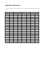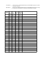
1
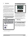
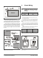
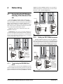
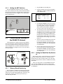
026-1710 Rev 1 05-15-07
CH Breaker Gateway
Installation and
Operation Manual
1640 Airport Road, Suite 104
Kennesaw, GA 31044
Phone: (770) 425-2724
Fax: (770) 425-9319
ALL RIGHTS RESERVED.
The information contained in this manual has been carefully checked and is believed to be accurate. However, Computer Process Controls, Inc. assumes no responsibility for any inaccuracies that may be contained herein. In no event will
Computer Process Controls, Inc. be liable for any direct, indirect, special, incidental, or consequential damages resulting
from any defect or omission in this manual, even if advised of the possibility of such damages. In the interest of continued
product development, Computer Process Controls, Inc. reserves the right to make improvements to this manual, and the
products described herein, at any time without notice or obligation.
Pow-R-Line and Pow-R-Command are a trademark of the Eaton Corporation. All rights reserved.
Table of Contents
1 OVERVIEW ................................................................................................................................................................... 1
1.1. THE CH BREAKER GATEWAY SYSTEM ........................................................................................................................ 1
1.2. THE CH BREAKER GATEWAY ...................................................................................................................................... 1
2 MOUNTING................................................................................................................................................................... 1
2.1. THE CH BREAKER GATEWAY ...................................................................................................................................... 1
3 POWER WIRING.......................................................................................................................................................... 2
3.1. CH BREAKER GATEWAY POWER WIRING .................................................................................................................... 2
4 NETWORKING............................................................................................................................................................. 3
4.1. CONNECTING THE CH BREAKER GATEWAY TO THE BREAKER PANELS ......................................................................
4.1.1. Terminating the MODBUS Network .....................................................................................................................
4.1.2. Setting the PRC100MOD Address .......................................................................................................................
4.1.3. Setting the NET Switches ......................................................................................................................................
4.2. CONNECTING THE GATEWAY TO THE RS485 I/O NETWORK .......................................................................................
4.2.1. Gateway Board Numbering ..................................................................................................................................
4.2.2. Setting the Baud Rate Dip Switches......................................................................................................................
4.2.3. Setting the RS485 I/O Termination Jumpers.........................................................................................................
3
3
3
4
4
4
4
5
5 SITE CONTROLLER SOFTWARE SETUP ............................................................................................................. 5
5.1. REFLECS.....................................................................................................................................................................
5.2. E2 AND EINSTEIN .........................................................................................................................................................
5.2.1. Board and Application Setup ................................................................................................................................
5.2.2. Adding Lighting Schedule Applications................................................................................................................
5.2.3. Proof Inputs and Light Outputs Setup...................................................................................................................
5
5
5
6
6
5.2.3.1. Proof Inputs Setup ............................................................................................................................................................. 6
5.2.3.2. Light Outputs Setup ............................................................................................................................................................ 7
6 SOFTWARE SETUP ..................................................................................................................................................... 7
6.1. CH BREAKER GATEWAY (HHT) ..................................................................................................................................
6.1.1. HHT Screens .........................................................................................................................................................
6.1.2. Configuration ........................................................................................................................................................
6.1.3. Status.....................................................................................................................................................................
7
8
8
9
7 CHARTS/APPENDICES .............................................................................................................................................. 9
7.1. MAPPING BREAKER NUMBERS TO BOARD AND POINTS (BD:PT)................................................................................. 9
7.2. 8RO MAPPING TABLE ................................................................................................................................................ 10
7.3. 16AI MAPPING TABLE................................................................................................................................................ 10
APPENDIX A:
WORKSHEETS .................................................................................................................................. 11
APPENDIX B:
TROUBLESHOOTING...................................................................................................................... 14
CH Breaker Gateway and MultiFlex CHB I&O Manual
Table of Contents • vi
1
Overview
1.2.
The CH Breaker Gateway
The CH Breaker Gateway is designed to allow CPC’s
family of site controllers to interface directly with CutlerHammer Pow-R-Command PRC100 breaker control panels (equipped with PRC100MOD System Controllers) to
activate and deactivate loads.
A Pow-R-Command™ breaker panel features remotely
controllable circuit breakers, each of which may be flipped
from OFF to ON and from ON to OFF by commanding the
PRC100MOD System Controller. The E2, Einstein, and
REFLECS site controllers communicate with the
PRC100MOD by use of the CH Breaker Gateway. The
Gateway has one MODBUS channel that interconnects up
to 4 PRC100MOD System Controllers and one RS485 I/O
channel that connects the Gateway to the CPC site controller.
A CH Breaker Gateway controls up to 48 inputs and 48
digital outputs, and to the CPC controller the board appears
identical to 8RO (relay output) boards and 16AI (input)
boards. The Gateway can emulate up to 3 16AI and 6 8RO
boards, depending on the amount of breaker groups used.
1.1.
The CH Breaker Gateway
System
Panel 1
PRC100MOD
Gateway
Board
Panel 2
PRC100MOD
Panel 3
PRC100MOD
Panel 4
PRC100MOD
MODBUS
NETWORK
I/O Network
5
9
4
11
3
10
2
1
8
1
2
3
4
5
6
7 6
LEGEND
Hand-Held Terminal Jack
7 Alarm Status LED
RS485 I/O Network
8 Dip Switch
9 Power Connector
RS485 Receiver Bus Net
I/O Net Term Jumpers
10 I/O Net Status LED
Receiver Bus Term Jumpers 11 Receiver Bus Status LED
General Status LED
26502044
Figure 1-2 - Gateway Board
The CH Breaker Gateway (Figure 1-2) allows you to
drive multiple breakers from a single virtual I/O point by
arranging them into breaker groups. Each group represents one output point (driven by a lighting control or
schedule application in the CPC site controller) and one input point (which sends a combined proof signal back to the
CPC site controller for proof checking).
The Gateway supports control of up to 48 breaker
groups, made up of breakers from up to 4 PRC100 panels,
each of which may have up to 48 breakers.
2
Mounting
2.1.
The CH Breaker Gateway
The Gateway is typically mounted in the same area as
the site controller, near the controller’s 16AI, 8RO, and
other RS485 Network peripherals. The Gateway is designed to fit into a standard 3" snap track (supplied with the
board) or may be mounted in a panel or on stand-offs. Follow the dimensions in Figure 2-1 for panel mounting.
CPC
Controller
Figure 1-1 - Typical Layout of Panels, Gateway, and Controller
A typical layout of a CPC-controlled PRC100 network
configuration is shown in Figure 1-1.
The CH Breaker Gateway System
Overview • 1
3
Power Wiring
3.1.
CH Breaker Gateway Power
Wiring
Input Voltage
24VAC, Class 2, 50/60Hz
Power
5VA
Table 3-1 - Gateway Power Requirements
The Gateway requires 24VAC power from a Class 2
center-tapped transformer.
Figure 2-1 - Gateway Board Mounting Dimensions
The Gateway should be mounted in an environment
with ambient temperature between -40°F and 150°F, with a
non-condensing relative humidity between 5% and 95%.
Gateway boards are not supplied with an enclosure but
come with a snap-track for easy installation. The insulation
sheet and I/O board must be removed from the track before
the track is mounted. The snap-track is mounted using the
0.1875” mounting slots. Figure 2-2 shows this installation
procedure.
CPC supplies several sizes of center-tapped transformers for powering multiple 16AIs, 8ROs, and other RS485
peripheral boards of the E2, Einstein, and REFLECS systems.
Refer to your controller’s user manual for information
on how to use the center-tapped transformers listed in Table 3-1 to power multiple RS485 I/O devices for the US and
Canada.
Figure 3-1 shows how to connect the 56VA and 80VA
transformers to the Gateway power connector.
Three-Board
P/N
Power Rating
Six-Board
640-0056
640-0080
56 VA
80 VA
Table 3-1-US and Canada Power Ratings for CPC Transformers
Figure 2-2 - Snap-Track Installation
2 • CH Breaker Gateway I&O Manual
Figure 3-1 - Pinout for the 56VA (640-0056) and 80VA (6400080) Transformers
026-1710 Rev 1 05-15-07
4
Networking
4.1.
Connecting the CH Breaker
Gateway to the Breaker Panels
(Figure 4-2). PRC100MOD boards have no on-board termination and must be terminated with a 150-ohm resistor
across the + and - terminals (Figure 4-2).
TERMINATION
TERMINATION
The Cutler-Hammer breaker panels connect to the
Gateway by MODBUS network connection. MODBUS is
a two-wire, polarity-sensitive network physically similar to
RS485. Using shielded, two-conductor 22AWG wire
(Belden #8761 or equivalent), connect all panels in a single
daisy-chain network configuration leading from the Gateway to each of the breaker panels in series.
PRC100MOD
PRC100MOD
Gateway
Board
TERMINATION
Figure 4-1 shows how to connect the wires to the
MODBUS connectors.
IMPORTANT! The polarity of the PRC100MOD connectors is the opposite of the Gateway board’s connector.
The wire color connected to the positive (+) terminal of the
Gateway board should be wired to the negative (-) terminal
on the breaker panels, and vice-versa.
NO
TERMINATION
Figure 4-2 - MODBUS Network Termination
4.1.2.
Setting the PRC100MOD Address
The PRC100MOD controllers on the Cutler-Hammer
breaker panels have a switch used to set the MODBUS address. This switch must be used to give each PRC100MOD
a unique address from 1 through 4. Figure 4-3 shows the
switch location and positions for each MODBUS address.
MODBUS
CONNECTORS
MODBUS
CONNECTOR
PRC100MOD
150Ω
PRC100MOD
Gateway
Board
GATEWAY
MODBUS
CONNECTOR
+ (BLACK)
- (WHITE)
- (BLACK)
0V (SHIELD)
0V (SHIELD)
+ (WHITE)
+ (BLACK)
- (WHITE)
0V (SHIELD)
PRC 100
MODBUS
CONNECTORS
NOTE: POLARITY
ON PRC 100
MODBUS
CONNECTORS
IS THE INVERSE
OF THE GATEWAY
WIRE + on Gateway
to - on PRC100s
WIRE - on Gateway
to + on PRC100s
Figure 4-1 - MODBUS Connection Diagram
4.1.1.
Terminating the MODBUS Network
MODBUS
CONNECTORS
MODBUS
CONNECTOR
PRC100MOD
PRC100MOD
Gateway
Board
GATEWAY
MODBUS
CONNECTOR
+ (BLACK)
- (WHITE)
- (BLACK)
0V (SHIELD)
0V (SHIELD)
+ (WHITE)
+ (BLACK)
- (WHITE)
The two devices at the ends of the MODBUS network
must be terminated. If the Gateway board is one of the end
devices, terminate the network using the three termination
jumpers located next to the Gateway MODBUS Connector
0V (SHIELD)
PRC 100
MODBUS
CONNECTORS
NOTE: POLARITY
ON PRC 100
MODBUS
CONNECTORS
IS THE INVERSE
OF THE GATEWAY
WIRE + on Gateway
to - on PRC100s
WIRE - on Gateway
to + on PRC100s
Figure 4-3 - MODBUS Addressing Switch Positions
Connecting the CH Breaker Gateway to the Breaker Panels
Networking • 3
4.1.3.
Setting the NET Switches
1.
Plug the HHT into the HHT jack.
The PRC100MOD controller has a pair of switches
that, when switched to the OFF position, breaks the MODBUS network connection. Verify that these switches are in
the ON position as shown in Figure 4-4 to enable MODBUS communication.
2.
From the opening screen, press the DOWN
ARROW key to display the Board Addresses
screen (Figure 4-6).
NET
SWITCHES
SET SWITCHES TO
"ON" POSITION
TO ENABLE
MODBUS NETWORK
#of Brk Grps: 2
ADDR Start End
16AI
1 - 1
8RO
1 - 1
Figure 4-6 - Starting Board Addresses Screen
3.
Press RIGHT ARROW to move the cursor to
the # of Brk Grps field. Enter the total number
of breaker groups you will be controlling.
When finished, press RIGHT ARROW to
move the cursor to the 16AI Start field.
4.
The end ranges for the 16AI and 8RO boards
will adjust based on the number you entered
in step 3. For every 16 breaker groups, another 16AI board number will be added to the
End range up to a maximum of 3. For every 8
breaker groups, another 8RO board number
will be added to the End range, up to a maximum of 6.
5.
Enter the 16AI board number that will be the
lowest in the Gateway’s Start-End range.
Press RIGHT ARROW. The End range value
will change to show the new Start-End range
of board numbers.
6.
Enter the 8RO board number that will be the
lowest in the Gateway’s Start-End range.
Press RIGHT ARROW. The End range value
will change to show the new Start-End range
of board numbers.
LEGEND
PUSH
ROCKER
UP
OFF
PUSH
ROCKER
DOWN
OFF
Figure 4-4 - MODBUS Network Enable/Disable Switches
4.2.
Connecting the Gateway to
the RS485 I/O Network
Using shielded two-conductor network cable (Belden
#8761 or equivalent), connect the RS485 I/O Network wire
to the three-terminal connector on the Gateway board as
shown in Figure 4-5. For further information about how
RS485 networks are configured, refer to your site controller’s user manual.
4.2.2.
Setting the Baud Rate Dip Switches
Dip switches 6 and 7 control the baud rate at which the
Gateway communicates with the site controller on the
RS485 Network. These switches must be set to the same
baud rate setting as the E2, Einstein, or REFLECS (usually
9600 baud).
Figure 4-5 - Connecting the Gateway to the RS485 Network
4.2.1.
There is no dip switch to set the MODBUS baud rate.
Since the PRC100MOD control board is fixed at 9600
baud, the Gateway board also uses a fixed 9600 baud rate
for MODBUS.
Gateway Board Numbering
The E2, Einstein, or REFLECS controller interprets the
Gateway board as one or more 16AI Analog Input boards
and one or more 8RO boards numbered in succession. Addressing the “boards” represented by the Gateway is
achieved using the HHT.
4 • CH Breaker Gateway I&O Manual
026-1710 Rev 1 05-15-07
5
Site Controller Software Setup
5.1.
REFLECS
GATEWAY
DIP SWITCH
I/O NETWORK OR
COM A AND D
BAUD RATE
1
2
3
4
5
6
7
8
I/O NET BAUD RATE SETTINGS
9600
19200
Figure 4-7 - Dip Switch Setting for Numbering Gateway
4.2.3. Setting the RS485 I/O Termination Jumpers
As part of a site controller’s RS485 I/O (COM A or
COM D) Network, a Gateway must be terminated if it is the
end device of a daisy chain. Refer to the controller’s user
manual for information about daisy chain networks and
how they are terminated.
To terminate the Gateway, set the I/O Network Jumpers
to the RIGHT position as shown in Figure 4-8. To unterminate the Gateway, set the jumpers to the LEFT position.
For backwards compatibility with REFLECS, the CH
Breaker Gateway behaves on the network identically to
16AI and 8RO boards. These devices should be set up and
addressed in the same way I/O boards are set up. Refer to
your controller’s manual for set up instructions.
5.2.
E2 and Einstein
5.2.1.
Board and Application Setup
Set up the number of boards on the I/O Network from
the Connected I/O screen. Press the Ikey to open the
Main Menu and press:
1.
2.
3.
System Configuration
Network Setup
Connected I/O Boards and Controllers
If using an Einstein controller, from the Main Status/
Home screen, press ((Actions), Network Status/
Setup, and then Connected I/O Boards & Controllers.
Figure 4-8 - Gateway RS485 I/O Network Termination
Figure 5-1 - Connected I/O Boards Screen
Add as many 16AIs and 8ROs as is necessary to cover
the entire Start-End range chosen in Section 4.2.1., Gateway Board Numbering. Press Jto save and exit.
REFLECS
Site Controller Software Setup • 5
5.2.2.
Adding Lighting Schedule Applications
For each group of breakers to be controlled separately,
set up a Lighting Schedule application from the Add New
Application screen.
1.
Add/Delete Application
2.
Add New Application
3.
DLOOK UP to select Lighting Control.
Enter the number of desired applications in
the How Many? field.
If using an Einstein controller, from the Home screen or
Enhanced Lighting Status screen, press ((Actions),
(Control Appl Setup), and then (Add Control Application). Press '(Look Up) to select Enhanced
Lighting. Press )(Home) to return to the Home screen.
5.2.3.
Proof Inputs and Light Outputs
Setup
Once the Lighting Schedule applications have been
added, set up the proof inputs and light outputs for each
Lighting application. The outputs of a Lighting Schedule
cell control the breakers on the Cutler-Hammer panels, and
the inputs are the combined proofs of all the breakers that
are part of the group being controlled by the application.
5.2.3.1.
Proof Inputs Setup
Set up 16AI board inputs in Proof Setup. To enable
proofing, set Enable Proofing to Yes for each Lighting application by accessing the Lighting Control Setup
screen. From the Main Menu:
1.
Press C(Lighting Sched) and select the a
Lighting application.
2.
E(Setup) to go the Setup screen for that
Lighting application.
If using an Einstein controller, from the Home screen
or Enhanced Lighting Status screen, press ((Actions),
TRY THIS: When creating a name for your
Lighting application, incorporate the application’s corresponding group number into the
name. For example, PARKLIGHTS01 associates the
parking lot breakers with Group 1.
(Setup), and choose the S1:Setup tab. (Note that the
Proof tab is S8 and the Outputs tab is S9).
Figure 5-2 - Setup Lighting Control
6 • CH Breaker Gateway I&O Manual
3.
Under the C1:Setup tab, set Enable
Proofing to Yes. (C8:Proof tab becomes visible once you cursor across the tabs.
See Figure 5-3.)
4.
Press B(Next Tab) or A(Prev Tab) to
cursor over to C8:Proof tab.
026-1710 Rev 1 05-15-07
Figure 5-3 - Lighting Proof Setup Screen
5.
Set Proof Type to ON Only. If the light
circuit is read as open when it should normally be closed, the 16AI board will send a "fail"
input relay to the controller. The Gateway
proofs both ON and OFF so that the user can
select the desired proof type as ALL Values, ON Only, or OFF Only. If any breaker within a group fails the proof, the entire
group will fail the proof.
6.
In the PROOF IN input, enter the virtual
board and point address of the proof input on
the gateway for the lighting group.
7.
Set Proof Delay to a minimum of two
minutes. (0:02:00)
Figure 5-4 - Lighting Outputs Setup Screen
For more information on setting up Lighting Schedules,
refer to your CPC site controller’s manual.
6
Software Setup
6.1.
CH Breaker Gateway (HHT)
Connect the HHT to the Gateway board via the HHT
jack (refer to figure Figure 1-2 #1). Use the HHT to assign
individual breakers to a particular group.
NOTE: Cycling power to all 48 breakers can
take up to 2 minutes. Choose a Proof Delay
that allows time for all breakers in the group
to switch ON and OFF.
8.
Press B(Next Tab) or A(Prev Tab) to
cursor over to C9: Outputs tab.
NOTE: If a breaker is assigned to a group
that is not set up, a proof failure message will
occur.
5.2.3.2. Light Outputs Setup
The Lighting Outputs Setup screen is where you will set
up the 8RO board and point numbers for each group for all
Lighting applications.
Refer to Table 7-1 to associate the inputs and outputs
with their corresponding group, board and point numbers.
CH Breaker Gateway (HHT)
Software Setup • 7
HHT Keys
Function
F1
Home screen key
F2
Quick access to status information
OPTION: 0
1= STATUS
2= DIAGS
3= CONFIG
Left and right arrow keys point to
the desired field to be configured
Up and down arrow keys scroll
through all breakers on panel
screens
Cancel
Enter
Deletes number you have chosen
and changes it to zero, and cancels
overrides on selected field
Figure 6-3 - Option Screen
Option No.
1
Status information that can be
overridden. (An asterisk "*" signifies a proof failure)
2
Diagnostics for troubleshooting
3
Configuration settings
Saves changes (optional - use the
down arrow)
.
Toggles between override ON and
OFF
Toggles between override ON and
OFF
Table 6-1 - HHT Key Functions
6.1.1.
HHT Screens
The Home screen is the first screen that appears. Press
F1 at any time to return to the Home screen.
CPC CH ModBus GW
810-3722
VER: 1.11F01
(PRESS
)
Function
Table 6-2 - Option Choices Chart
6.1.2.
Configuration
Use the left or right arrows to activate the OPTION:
field and choose 3 to start configuring each Panel’s breakers to groups. Press DOWN ARROW to move to the next
screen.
BRK
BRK
BRK
PANEL 1
1 GRP
2 GRP
3 GRP
1
1
1
Figure 6-1 - Home Screen
Figure 6-4 - Panel 1 Breakers to Group Screen
Press the down arrow key to move to the Starting Board
Addresses screen.
From this screen you can begin assigning breakers on
panels 1 through 4 to breaker groups. Refer to Table A-1
for a diagram of the breaker panel and the breaker number
to group assignment.
#of Brk Grps: 2
ADDR Start End
16AI
1 - 1
8RO
1 - 1
Use the number keys to enter the group number.
Change the group number to the group you want to associate the breaker with (a maximum number of 48).
Press DOWN ARROW to scroll through all 48 breakers on each of the four panels and set the group numbers as
you scroll through the breakers.
Figure 6-2 - Starting Board Addresses Screen
Next, arrow down to the Option screen.
8 • CH Breaker Gateway I&O Manual
NOTE: If a breaker is assigned to a group
that is not set up, a proof failure message will
occur.
026-1710 Rev 1 05-15-07
6.1.3.
Status
From the Option screen, select 1 for Status. The Status
screen shows the status of the 48 groups and shows the ON
or OFF state of each group and any proof failures (a proof
failure is indicated by "*" after the ON or OFF state). Press
the down arrow key to scroll through the groups. After the
groups are displayed, continue pressing the down arrow
key to see the ON or OFF state and any proof failures of
each of the 48 breakers and all panels.
If a group is not assigned or set to zero, a "-" will appear
as the breaker status.
OPTION: 1
1= STATUS
2= DIAGS
3= CONFIG
Figure 6-5 - Option Screen
7
Charts/Appendices
7.1.
Mapping Breaker Numbers
to Board and Points (Bd:Pt)
Up to a maximum of 48 groups can be set up, but there
is no limitation to the number of breakers that may belong
to a single group.
Y represents the starting 16AI address and X represents
the starting 8RO address of the Gateway configured in Section 6.1.1., HHT Screens.
Light
Schedule
Proof
In
(Bd)
Proof
In
(Pt)
Lights
Output
(Bd)
Lights
Output
(Pt)
Group
16AI
Addr
16AI
Points
8RO
Addr
8RO
Points
1
Y
1
X
1
2
Y
2
X
2
3
Y
3
X
3
4
Y
4
X
4
5
Y
5
X
5
6
Y
6
X
6
7
Y
7
X
7
8
Y
8
X
8
9
Y
9
X+1
1
10
Y
10
X+1
2
11
Y
11
X+1
3
12
Y
12
X+1
4
13
Y
13
X+1
5
14
Y
14
X+1
6
15
Y
15
X+1
7
16
Y
16
X+1
8
17
Y+1
1
X+2
1
18
Y+1
2
X+2
2
19
Y+1
3
X+2
3
20
Y+1
4
X+2
4
21
Y+1
5
X+2
5
22
Y+1
6
X+2
6
23
Y+1
7
X+2
7
24
Y+1
8
X+2
8
Table 7-1 - Mapping Group Numbers to Point Numbers
Mapping Breaker Numbers to Board and Points (Bd:Pt)
Charts/Appendices • 9
25
Y+1
9
X+3
1
26
Y+1
10
X+3
2
27
Y+1
11
X+3
3
28
Y+1
12
X+3
4
29
Y+1
13
X+3
5
30
Y+1
14
X+3
6
31
Y+1
15
X+3
7
32
Y+1
16
X+3
8
33
Y+2
1
X+4
1
34
Y+2
2
X+4
2
35
Y+2
3
X+4
3
36
Y+2
4
X+4
4
37
Y+2
5
X+4
5
38
Y+2
6
X+4
6
39
Y+2
7
X+4
7
40
Y+2
8
X+4
8
41
Y+2
9
X+5
1
42
Y+2
10
X+5
2
43
Y+2
11
X+5
3
44
Y+2
12
X+5
4
45
Y+2
13
X+5
5
46
Y+2
14
X+5
6
47
Y+2
15
X+5
7
48
Y+2
16
X+5
8
7.3.
16AI Mapping Table
Table 7-3 shows how the outputs of the 16AI Board are
connected to group numbers.
16AI
Board #
16AI Board
Inputs
Associated Group
Number
1
16 Inputs
1-16
2
16 Inputs
17-32
3
16 Inputs
33-48
Table 7-3 - 16AI Mapping
Table 7-1 - Mapping Group Numbers to Point Numbers
7.2.
8RO Mapping Table
Table 7-2 shows how the outputs of the 8RO Board are
connected to group numbers.
8RO
Board #
8RO Board
Outputs
Associated Group
Number
1
8 Outputs
1-8
2
8 Outputs
9-16
3
8 Outputs
17-24
4
8 Outputs
25-32
5
8 Outputs
33-40
6
8 Outputs
41-48
Table 7-2 - 8RO Mapping
10 • CH Breaker Gateway I&O Manual
026-1710 Rev 1 05-15-07
Appendix A: Worksheets
Use the workspace below to assign breakers to groups. Refer to Table A-2 for group number board and point assignment.
Panel 1 Breakers
Group#
Panel 2 Breakers
Group#
Group#
Panel 3 Breakers
Group#
Group#
Panel 4 Breakers
Group#
Group#
Group#
1
___
25
___
1
___
25
___
1
___
25
___
1
___
25
___
2
___
26
___
2
___
26
___
2
___
26
___
2
___
26
___
3
___
27
___
3
___
27
___
3
___
27
___
3
___
27
___
4
___
28
___
4
___
28
___
4
___
28
___
4
___
28
___
5
___
29
___
5
___
29
___
5
___
29
___
5
___
29
___
6
___
30
___
6
___
30
___
6
___
30
___
6
___
30
___
7
___
31
___
7
___
31
___
7
___
31
___
7
___
31
___
8
___
32
___
8
___
32
___
8
___
32
___
8
___
32
___
9
___
33
___
9
___
33
___
9
___
33
___
9
___
33
___
10
___
34
___
10
___
34
___
10
___
34
___
10
___
34
___
11
___
35
___
11
___
35
___
11
___
35
___
11
___
35
___
12
___
36
___
12
___
36
___
12
___
36
___
12
___
36
___
13
___
37
___
13
___
37
___
13
___
37
___
13
___
37
___
14
___
38
___
14
___
38
___
14
___
38
___
14
___
38
___
15
___
39
___
15
___
39
___
15
___
39
___
15
___
39
___
16
___
40
___
16
___
40
___
16
___
40
___
16
___
40
___
17
___
41
___
17
___
41
___
17
___
41
___
17
___
41
___
18
___
42
___
18
___
42
___
18
___
42
___
18
___
42
___
19
___
43
___
19
___
43
___
19
___
43
___
19
___
43
___
20
___
44
___
20
___
44
___
20
___
44
___
20
___
44
___
21
___
45
___
21
___
45
___
21
___
45
___
21
___
45
___
22
___
46
___
22
___
46
___
22
___
46
___
22
___
46
___
23
___
47
___
23
___
47
___
23
___
47
___
23
___
47
___
24
___
48
___
24
___
48
___
24
___
48
___
24
___
48
___
Table A-1 - Assigning Breakers to Group Numbers
16AI Address = ____ Fill in the Gateway 16AI board address that you set with the HHT. For groups 17-32, add 1;
for groups 33-48, add 2.
8RO Address = ____Fill in the Gateway 8RO board address that you set with the HHT for Groups 1-8. For Groups
9-16, add 1; for 17-24, add 2; for 25-32, add 3; for 33-40, add 4; for 41-48, add 5.
Light
Schedule
Proof
In
(Bd)
Proof
In
(Pt)
Lights
Output
(Bd)
Lights
Output
(Pt)
Group
16AI
Addr
16AI
Points
8RO
Addr
8RO
Points
1
1
1
2
2
2
3
3
3
4
4
4
5
5
5
6
6
6
7
7
7
8
8
8
9
9
1
10
10
2
11
11
3
12
12
4
13
13
5
14
14
6
15
15
7
16
16
8
17
1
1
18
2
2
19
3
3
20
4
4
21
5
5
22
6
6
23
7
7
24
8
8
25
9
1
26
10
2
27
11
3
28
12
4
29
13
5
30
14
6
31
15
7
32
16
8
Table A-2 - Mapping Group Numbers to Point Numbers
Group Name
33
1
1
34
2
2
35
3
3
36
4
4
37
5
5
38
6
6
39
7
7
40
8
8
41
9
1
42
10
2
43
11
3
44
12
4
45
13
5
46
14
6
47
15
7
48
16
8
Table A-2 - Mapping Group Numbers to Point Numbers
Appendix B: Troubleshooting
SYMPTOM
Board Offline
POSSIBLE PROBLEM
I/O Network Problems
SOLUTION
Check wiring polarity. Verify the
485+ uses one color and the 485uses the other color throughout
the network.
Check each connector for any
loose wires or frayed strands
between connectors.
Termination Jumpers Set Incorrectly
Verify all three jumpers are set in
the UP position if the board is at
the end of a daisy chain, and that
all other boards are not terminated (jumpers in DOWN position).
Board Not Receiving Power
Refer to Figure 3-1 for the following steps:
1. Verify proper transformer wiring. Check that the 28 VAC secondary switch is in the ON
position.
2. Verify that the secondary
power is 28 VAC and the wires
are connected properly.
3. Check Fuses F5 and F6.
4. Verify line voltage is connected to high-line side of the
control power transformer.
Dip Switches Set Incorrectly
Check 8RO address, 16AI
address, and baud rate settings.
Refer to Section 4.2.1., Gateway
Board Numbering and Section
4.2.2., Setting the Baud Rate Dip
Switches.
Note: after changing dip switch
settings, cycle power to board
using the 28 VAC secondary
power switch (flip to the OFF
position and then to the ON position).
SYMPTOM
HHT Home screen displays
FAIL: I/O NET.
POSSIBLE PROBLEM
SOLUTION
Communication has been lost
between the site controller and
the Gateway.
Check I/O Net wiring.
The Gateway is not configured
with at least one group. It must
be configured before the Gateway will communicate with the
PRC100MODs on the MODBUS Network.
If Receiver Bus Status LED is
not blinking, assign at least one
breaker to a group (1-16). If the
Group number is 0 (zero), it is
undefined.
Red Alarm Status LED is blinking once per second.
Check that 16AI and 8RO
addresses are set with the HHT,
and boards are defined in the site
controller.
I/O Net Status LED is not blinking.
HHT Home screen displays
FAIL: COMM BUS.
The red Alarm Status LED is on
solid.
Communication has been lost
between the Gateway and the
PRC100MOD(s).
If Receiver Bus Status LED is
blinking rapidly, check MODBUS wiring and PRC100MOD
addressing.