1
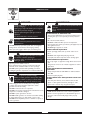
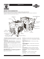
Owner’s Manual
Manuel de l'utilisateur
Manual del Propietario
Questions? Help is just a moment away!
Vous avez des questions? Vous n'avez pas besoin d'aller
loin pour trouver de l'aide!
030239
(2000W)
Preguntas? La ayuda es justa un momento lejos!
Call: Generator Helpline
Appelez: Ligne d'assistance de Générateur
Llame: Línea Directa del Generador
1-800-743-4115 M-F 8-5 CT
web: www.briggsandstratton.com
CAUTION
ATTENTION
PRECAUCIÓN
Before using this product, read this
manual and follow all Safety Rules and
Operating Instructions.
Avant d’utiliser ce produit, veuillez lire
le manuel et suivre toutes les directives
relatives à la sécurité et à l’utilisation.
Antes de utilizar el producto, lea este
manual y siga todas las Reglas de
Seguridad e Instrucciones de Uso.
BRIGGS & STRATTON POWER PRODUCTS GROUP, LLC
JEFFERSON, WISCONSIN, U.S.A.
Manual No. 197561GS
Revision 2 (06/27/2005)
15750102000
2000W Generator
TABLE OF CONTENTS
SAFETY RULES
Safety Rules. . . . . . . . . . . . . . . . . . . . . . . . . . . . . . . . . . . . 2-4
Know Your Generator . . . . . . . . . . . . . . . . . . . . . . . . . . . . 5
Assembly. . . . . . . . . . . . . . . . . . . . . . . . . . . . . . . . . . . . . . 6-7
Operation . . . . . . . . . . . . . . . . . . . . . . . . . . . . . . . . . . . . 8-13
Maintenance . . . . . . . . . . . . . . . . . . . . . . . . . . . . . . . . . 14-17
Storage . . . . . . . . . . . . . . . . . . . . . . . . . . . . . . . . . . . . . . . . 18
Troubleshooting . . . . . . . . . . . . . . . . . . . . . . . . . . . . . . . . . 19
Notes . . . . . . . . . . . . . . . . . . . . . . . . . . . . . . . . . . . . . . 20-21
Emmision Control Warranty. . . . . . . . . . . . . . . . . . . . . . . 22
Warranty . . . . . . . . . . . . . . . . . . . . . . . . . . . . . . . . . . . . . . 23
This is the safety alert symbol. It is used to
alert you to potential personal injury
hazards. Obey all safety messages that follow
this symbol to avoid possible injury or death.
The safety alert symbol ( ) is used with a signal word
(DANGER, CAUTION, WARNING), a pictorial and/or a
safety message to alert you to hazards. DANGER
indicates a hazard which, if not avoided, will result in death
or serious injury. WARNING indicates a hazard which, if
not avoided, could result in death or serious injury.
CAUTION indicates a hazard which, if not avoided, might
result in minor or moderate injury. CAUTION, when
used without the alert symbol, indicates a situation that
could result in equipment damage. Follow safety messages
to avoid or reduce the risk of injury or death.
EQUIPMENT
DESCRIPTION
Read this manual carefully and become familiar
with your generator. Know its applications, its
limitations and any hazards involved.
This generator is an engine–driven, revolving field,
alternating current (AC) generator. It was designed to
supply electrical power for operating compatible electrical
lighting, appliances, tools and motor loads. The generator’s
revolving field is driven at about 3,600 rpm by a singlecylinder engine.
WARNING
The engine exhaust from this product contains
chemicals known to the State of California to cause
cancer, birth defects, or other reproductive harm.
Hazard Symbols and Meanings
CAUTION! DO NOT exceed the generator’s
wattage/amperage capacity. See “Don’t Overload the
Generator”.
Every effort has been made to ensure that information in
this manual is accurate and current. However, we reserve
the right to change, alter or otherwise improve the
product and this document at any time without prior
notice.
The Emission Control System for this generator is
warranted for standards set by the Environmental
Protection Agency.
Toxic Fumes
Electrocution
Electrical Shock
Hot Surface
Explosion
Fire
Kickback
Copyright © 2005 Briggs & Stratton Power Products
Group, LLC. All rights reserved. No part of this material
may be reproduced or transmitted in any form by any
means without the express written permission of Briggs &
Stratton Power Products Group, LLC.
2
Explosive Pressure
Chemical Burn
2000W Generator
WARNING
DANGER
Storage batteries give off explosive hydrogen gas
during recharging.
Hydrogen gas stays near battery for a long time
after battery has been charged.
Slightest spark will ignite hydrogen and cause
explosion.
You can be blinded or severely injured.
Battery electrolyte fluid contains acid and is
extremely caustic.
Contact with battery fluid will cause severe
chemical burns.
Fuel and its vapors are extremely flammable and
explosive.
Fire or explosion can cause severe burns or
death.
WHEN ADDING OR DRAINING FUEL
• Turn generator OFF and let it cool at least 2 minutes before
removing fuel cap. Loosen cap slowly to relieve pressure in
tank.
• Fill or drain fuel tank outdoors.
• DO NOT overfill tank. Allow space for fuel expansion.
• Keep fuel away from sparks, open flames, pilot lights, heat, and
other ignition sources.
• DO NOT light a cigarette or smoke.
WHEN STARTING EQUIPMENT
• Ensure spark plug, muffler, fuel cap and air cleaner are in
place.
• DO NOT crank engine with spark plug removed.
• If fuel spills, wait until it evaporates before starting engine.
WHEN OPERATING EQUIPMENT
• Do not tip engine or equipment at angle which causes fuel to
spill.
• This generator is not for use in mobile equipment or marine
applications.
WHEN TRANSPORTING OR REPAIRING
EQUIPMENT
• Transport/repair with fuel tank EMPTY or with fuel shutoff
valve OFF.
• Disconnect spark plug wire.
WHEN STORING FUEL OR EQUIPMENT WITH FUEL
IN TANK
• Store away from furnaces, stoves, water heaters, clothes
dryers or other appliances that have pilot light or other
ignition source because they can ignite fuel vapors.
• DO NOT allow any open flame, spark, heat, or lit cigarette
during and for several minutes after charging a battery.
• Wear protective goggles, rubber apron, and rubber gloves.
WARNING
Running generator gives off carbon monoxide,
an odorless, colorless, poison gas.
Breathing carbon monoxide will cause nausea,
fainting or death.
• Operate generator ONLY outdoors.
• Keep exhaust gas from entering a confined area through
windows, doors, ventilation intakes or other openings.
• DO NOT operate generator inside any building or enclosure,
including the generator compartment of a recreational vehicle (RV).
WARNING
Generator produces powerful voltage.
Failure to isolate generator from power utility
can result in death or injury to electric utility
workers due to backfeed of electrical energy.
• When using generator for backup power, notify utility
company. Use approved transfer equipment to isolate
generator from electric utility.
• DO NOT touch bare wires or receptacles.
• DO NOT use generator with electrical cords which are worn,
frayed, bare or otherwise damaged.
• DO NOT operate generator in the rain.
• DO NOT handle generator or electrical cords while standing
in water, while barefoot, or while hands or feet are wet.
• DO NOT allow unqualified persons or children to operate or
service generator.
WARNING
• This generator does not meet U. S. Coast Guard Regulation
33CFR-183 and should not be used on marine applications.
• Failure to use the appropriate U. S. Coast Guard approved
generator could result in bodily injury and/or property
damage.
3
2000W Generator
CAUTION
WARNING
Excessively high operating speeds increase risk of injury
and damage to generator.
Excessively low speeds impose a heavy load.
Rapid retraction of starter cord (kickback) will
pull hand and arm toward engine faster than
you can let go.
Broken bones, fractures, bruises or sprains
could result.
• DO NOT tamper with governed speed. Generator supplies
correct rated frequency and voltage when running at governed
speed.
• DO NOT modify generator in any way.
• When starting engine, pull cord slowly until resistance is felt
and then pull rapidly to avoid kickback.
• NEVER start or stop engine with electrical devices plugged in
and turned on.
CAUTION
Exceeding generators wattage/amperage capacity can
damage generator and/or electrical devices connected
to it.
WARNING
Unintentional sparking can result in fire or
electric shock.
• See “Don’t Overload Generator”.
• Start generator and let engine stabilize before connecting
electrical loads.
• Connect electrical loads in OFF position, then turn ON for
operation.
• Turn electrical loads OFF and disconnect from generator
before stopping generator.
WHEN ADJUSTING OR MAKING REPAIRS TO YOUR
GENERATOR
• Disconnect the spark plug wire from the spark plug and place
the wire where it cannot contact spark plug.
WHEN TESTING FOR ENGINE SPARK
• Use approved spark plug tester.
• DO NOT check for spark with spark plug removed.
CAUTION
Improper treatment of generator can damage it and
shorten its life.
WARNING
• Use generator only for intended uses.
• If you have questions about intended use, ask dealer or call
1-800-743-4115.
• Operate generator only on level surfaces.
• DO NOT expose generator to excessive moisture, dust, dirt,
or corrosive vapors.
• DO NOT insert any objects through cooling slots.
• If connected devices overheat, turn them off and disconnect
them from generator.
• Shut off generator if:
-electrical output is lost;
-equipment sparks, smokes, or emits flames;
-unit vibrates excessively.
Running engines produce heat. Temperature of
muffler and nearby areas can reach or exceed
150°F (65°C).
Severe burns can occur on contact.
Combustible debris, such as leaves, grass, brush,
ect. can catch fire.
• DO NOT touch hot surfaces.
• Allow equipment to cool before touching.
• The generator must be at least 5 feet from structures having
combustible walls and/or other combustible materials.
• Keep at least 3 feet of clearance on all sides of generator for
adequate cooling, maintenance and servicing.
• In the State of California a spark arrester is required by law
(Section 4442 of the California Public Resources Code).
Other states may have similar laws. Federal laws apply on
federal lands. If you equip the muffler with a spark arrester, it
must be maintained in effective working order.
4
2000W Generator
KNOW YOUR GENERATOR
Read this owner’s manual and safety rules before operating your generator.
Compare the illustrations with your generator to familiarize yourself with the locations of various controls and
adjustments. Save this manual for future reference.
Engine ON/OFF Switch
Oil Fill/Drain
Fuel Tank
Fuel Shut-Off
Valve
Recoil Starter
Choke Lever
Circuit
Breaker (AC)
120 Volt AC, 15 Amp
Receptacle
12 Volt DC, 8.3 Amp
Accessory Jacks
Spark Plug
Air Cleaner
Data Tag
Grounding Lug
12 Volt DC, 8.3 Amp Accessory Jacks — May be used
to power 12 Volt DC electrical devices or recharge 12 Volt
DC batteries.
Data Tag — Provides model, revision and serial number
of generator. Please have these readily available if calling for
assistance.
120 Volt AC, 15 Amp Receptacles — May be used to
supply electrical power for the operation of 120 Volt AC,
single phase, 60 Hz electrical lighting, appliance, tool and
motor loads.
Engine ON/OFF Switch — Used to stop a running
engine.
Air Cleaner — Protects engine by filtering dust and debris
out of intake air.
Fuel Tank — Capacity of 1.32 U.S. gallons (5.0 liters) of
fuel.
Choke Lever — Used to manually provide proper starting
mixture when engine is cold.
Grounding Lug — Use this connection to properly
ground the generator. See ”System Ground” on page 8.
Circuit Breaker (AC) — Receptacles are provided with a
push-to-reset circuit breaker to protect the generator
against electrical overload.
Oil Fill/Drain — Access to oil fill dipstick and engine oil
drain plug.
Fuel Shut-Off Valve — Use this valve to turn the fuel
supply on and off.
Recoil Starter — Used for starting the engine.
Spark Plug — Access to engine spark plug.
5
2000W Generator
ASSEMBLY
Refer to Figure 1 and install the wheel kit as follows:
1. Tip generator up onto handle end.
Your generator requires some assembly and is ready for
use after it has been properly serviced with the
recommended oil and fuel.
2.
Slide axle through both axle mounting brackets on
cradle frame.
3.
Slide a flat washer and wheel over the axle (Figure 1).
If you have any problems with the assembly of your
generator, please call the generator helpline at
1-800-743-4115.
Figure 1 — Install Wheel Kit
Axle
Remove Generator From Carton
1.
Set the carton on a rigid flat surface.
2.
Carefully open the top flaps of the shipping carton.
3.
Cut down corners at ends of carton from top to
bottom and lay carton down flat.
4.
Remove all packing material, carton fillers, etc.
5.
Remove generator from shipping carton.
Flat Washer
Cotter Pin
Wheel
Carton Contents
4.
Slide another flat washer over the axle.
5.
Insert cotter pin through hole on axle. Bend the ends
of the cotter pin over the axle with a needle-nose
pliers to retain wheel.
6.
Repeat step 3 thru 5 to secure second wheel.
7.
Tip generator back down onto wheels.
Check all contents against those listed below:
• Main unit
• Engine oil
• Owner’s manual
BEFORE STARTING
ENGINE
• Battery charge cables
• Wheel kit
If any parts are missing or damaged, call the generator
helpline at 1-800-743-4115.
Add Oil
Install Wheel Kit
IMPORTANT: Any attempt to crank or start the engine
before it has been properly serviced with the
recommended oil may result in an engine failure.
NOTE: While the wheel kit is designed to greatly improve
the portability of your generator, it is not intended for
over-the-road use.
You will need a needle-nose pliers to install this kit.
NOTE: When adding oil to the engine crankcase, use only
high quality detergent oil rated with API service
classification SF, SG, SH, SJ or higher. DO NOT use special
additives.
6
2000W Generator
1.
Choose a viscosity according to the table below:
WARNING
30
Fuel and its vapors are extremely flammable and
explosive.
Fire or explosion can cause severe burns or
death.
5W-30, 10W-30
Synthetic 5W-30, 10W-30
°F
°C
-20
-30
0
-20
20
-10
32
0
40
60
10
80
20
WHEN ADDING FUEL
• Turn generator OFF and let it cool at least 2 minutes before
removing fuel cap. Loosen cap slowly to relieve pressure in
tank.
• Fill fuel tank outdoors.
• DO NOT overfill tank. Allow space for fuel expansion.
• Keep fuel away from sparks, open flames, pilot lights, heat, and
other ignition sources.
• DO NOT light a cigarette or smoke.
100
30
40
STARTING TEMPERATURE RANGE ANTICIPATED BEFORE NEXT OIL CHANGE
* The use of multi-viscosity oils (5W-30, 10W-30, etc.) in
temperatures above 40°F (4°C) will result in higher than
normal oil consumption. When using a multi-viscosity oil,
check oil more frequently.
** If using SAE 30 oil in temperatures below 40°F (4°C), it
will result in hard starting and possible engine bore damage
due to inadequate lubrication.
NOTE: Synthetic oil meeting ILSAC GF-2, API certification
mark and API service symbol with “SJ/CF ENERGY
CONSERVING” or higher, is an acceptable oil at all
temperatures. Use of synthetic oil does not alter required
oil change intervals.
To Add Engine Oil:
2. Place the generator on a level surface.
3.
1.
Use clean, fresh, regular UNLEADED fuel with a
minimum of 85 octane with equipment. DO NOT use
fuel which contains Methanol. DO NOT mix oil with
fuel.
2.
Clean area around fuel fill cap, remove cap.
3.
Slowly add regular unleaded fuel to fuel tank. Be
careful not to overfill. Allow about 1.5" of tank space
for fuel expansion as shown in Figure 3.
Remove oil filler cap and wipe dipstick clean (Figure 2).
Figure 3 — Fuel Level
Figure 2 — Adding Engine Oil
1.5” Airspace
NOTE: Occasionally clear the fuel strainer of any dirt,
rust, or other particulate matter.
Oil Filler Neck
4.
If the oil level is not at the point of overflowing from the
oil filler neck, slowly fill engine with recommended oil.
5.
Reinstall oil filler cap and tighten securely.
6.
Check the engine oil level before starting each time
thereafter.
4.
Install fuel cap and wipe up any spilled fuel.
Occasionally you may hear a light “spark knock” or
“pinging” (metallic rapping noise) while operating under
heavy loads. This is no cause for concern. If spark knock or
pinging occurs at a steady engine speed under normal load,
change brands of fuel or obtain a higher octane rated fuel.
If pinging or spark knock persists, see your local Briggs &
Stratton repair center.
Add Fuel
NOTE: This gasoline engine is certified to operate on
gasoline.
7
2000W Generator
USING THE GENERATOR
Generator Location
Generator Clearance
System Ground
WARNING
The generator has a system ground that connects the
generator frame components to the ground terminals on
the AC output receptacles. The system ground is not
connected to the AC neutral wire. If the generator is
tested by a receptacle tester, it will not show the same
ground circuit condition as for a home receptacle.
Running generator gives off carbon monoxide,
an odorless, colorless, poison gas.
Breathing carbon monoxide will cause nausea,
fainting or death.
• Operate generator ONLY outdoors.
• Keep exhaust gas from entering a confined area through
windows, doors, ventilation intakes or other openings.
• DO NOT operate generator inside any building or enclosure,
including the generator compartment of a recreational vehicle (RV).
Special Requirements
There may be Federal or State Occupational Safety and
Health Administration (OSHA) regulations, local codes, or
ordinances that apply to the intended use of the generator.
Please consult a qualified electrician, electrical inspector, or
the local agency having jurisdiction.
The generator must be at least 5 ft. (152 cm) from
structures having combustible walls and/or other
combustible materials. Leave at least 3 ft. (92 cm) all
around generator including overhead, for adequate cooling,
maintenance and servicing.
• In some areas, generators are required to be registered
with local utility companies.
Place generator in a well ventilated area, which will allow
for removal of deadly exhaust gas. DO NOT place
generator where exhaust gas could accumulate and enter
inside or be drawn into a potentially occupied building.
Ensure exhaust gas is kept away from any windows, doors,
ventilation intakes or other openings that can allow exhaust
gas to collect in a confined area (Figure 4). Prevailing winds
and air currents should be taken into consideration when
positioning generator.
• If the generator is used at a construction site, there may
be additional regulations which must be observed.
Connecting to a Building’s Electrical
System
Connections for standby power to a building’s electrical
system must be made by a qualified electrician. The
connection must isolate the generator power from utility
power, and must comply with all applicable laws and
electrical codes.
Figure 4 — Generator Clearance
WARNING
Generator produces powerful voltage.
Failure to isolate generator from power utility
can result in death or injury to electric utility
workers due to backfeed of electrical energy.
• When using generator for backup power, notify utility
company. Use approved transfer equipment to isolate
generator from electric utility.
• DO NOT touch bare wires or receptacles.
• DO NOT use generator with electrical cords which are worn,
frayed, bare or otherwise damaged.
• DO NOT operate generator in the rain.
• DO NOT handle generator or electrical cords while standing
in water, while barefoot, or while hands or feet are wet.
• DO NOT allow unqualified persons or children to operate or
service generator.
Exhaust Port
8
2000W Generator
OPERATING THE
GENERATOR
4.
Place the engine switch in the “On” position (Figure 7).
Figure 7 — Engine Switch in On Position
CAUTION
Exceeding generators wattage/amperage capacity can
damage generator and/or electrical devices connected
to it.
• See “Don’t Overload Generator”.
• Start generator and let engine stabilize before connecting
electrical loads.
• Connect electrical loads in OFF position, then turn ON for
operation.
• Turn electrical loads OFF and disconnect from generator
before stopping generator.
5.
WARNING
Rapid retraction of starter cord (kickback) will
pull hand and arm toward engine faster than
you can let go.
Broken bones, fractures, bruises or sprains
could result.
Starting the Engine
Disconnect all electrical loads from the generator. Use the
following start instructions:
1.
Make sure unit is on a level surface.
• When starting engine, pull cord slowly until resistance is felt
and then pull rapidly to avoid kickback.
• NEVER start or stop engine with electrical devices plugged in
and turned on.
IMPORTANT: Failure to start and operate unit on a level
surface will cause the unit not to start or shut down during
operation.
2.
Grasp starter grip and slowly pull the rope until you
feel some resistance, then pull the cord out with a
rapid full arm stroke. Let rope return slowly. DO NOT
let rope “snap back” against the unit.
Turn the fuel valve to the “Open” position (fully
clockwise) (Figure 5).
NOTE: If engine starts after 3 pulls, but fails to run for
more than 10 seconds, check for proper oil level in
crankcase. This unit is equipped with a Oil Alert System
(see page 10).
Figure 5 — Fuel Valve in Open Position
WARNING
3.
Running engines produce heat. Temperature of
muffler and nearby areas can reach or exceed
150°F (65°C).
Severe burns can occur on contact.
Combustible debris, such as leaves, grass, brush,
ect. can catch fire.
Slide the choke lever to the “Choke” position (all the
way to the right) (Figure 6).
• DO NOT touch hot surfaces.
• Allow equipment to cool before touching.
• The generator must be at least 5 feet from structures having
combustible walls and/or other combustible materials.
• Keep at least 3 feet of clearance on all sides of generator for
adequate cooling, maintenance and servicing.
• In the State of California a spark arrester is required by law
(Section 4442 of the California Public Resources Code).
Other states may have similar laws. Federal laws apply on
federal lands. If you equip the muffler with a spark arrester, it
must be maintained in effective working order.
Figure 6 — Choke Lever
9
2000W Generator
6.
Charging a Battery
Slide the choke lever left to the “Run” position as the
engine warms up.
Your generator has the capability of recharging a discharged
12 Volt automotive or utility style storage battery. DO
NOT use the unit to charge any 6 Volt batteries. DO NOT
use the unit to crank an engine having a discharged battery.
NOTE: Under no load conditions, the engine speed may
vary slightly faster or slower until engine temperatures
stabilize.
DANGER
Connecting Electrical Loads
Storage batteries give off explosive hydrogen gas
during recharging.
Hydrogen gas stays near battery for a long time
after battery has been charged.
Slightest spark will ignite hydrogen and cause
explosion.
You can be blinded or severely injured.
Battery electrolyte fluid contains acid and is
extremely caustic.
Contact with battery fluid will cause severe
chemical burns.
• Let engine stabilize and warm up for a few minutes after
starting.
• DO NOT connect 240 Volt loads to 120 Volt receptacles.
• DO NOT connect 3–phase loads to the generator.
• DO NOT connect 50 Hz loads to the generator.
• Plug in and turn on the desired 120 Volt AC, single
phase, 60 Hertz electrical loads.
• DO NOT OVERLOAD THE GENERATOR. See
“Don’t Overload the Generator”.
• DO NOT allow any open flame, spark, heat, or lit
cigarette during and for several minutes after charging a
battery.
• Wear protective goggles, rubber apron, and rubber gloves.
Stopping the Engine
1.
Turn OFF and unplug all electrical loads from the unit.
NEVER start or stop engine with electrical devices
plugged in and turned on.
2.
Let engine run at no–load for two minutes to stabilize
the internal temperatures.
To recharge 12 Volt batteries, proceed as follows:
1. If necessary, clean battery posts or terminals.
3.
Move engine switch to the “Off” position.
2.
4.
Turn the fuel valve to the “Close” position (fully
counterclockwise).
Check fluid level in all battery cells. If necessary, add
ONLY distilled water to cover separators in battery
cells. DO NOT use tap water.
3.
If the battery is equipped with vent caps, make sure
they are installed and are tight.
4.
Connect battery charge cable connector plug to the
12 Volt DC panel receptacle.
5.
Connect battery charge cable clamp with red handle
to battery post or terminal indicated by Positive,
POS or (+) (Figure 8).
CAUTION
DO NOT stop engine by moving choke lever to “Choke”
position. Backfire, fire or engine damage could occur.
NOTE: In an emergency, stop the engine by moving the
engine switch to the “Off” position.
Oil Alert System
The Oil Alert System is designed to prevent engine damage
caused by an insufficient amount of oil in the crankcase.
Before the oil level in the crankcase can fall below a safe
limit, the Oil Alert System will automatically shut down the
engine (the engine switch will remain in the “On” position).
Figure 8 — Battery Connections
To 12 Volt DC Panel
Receptacle
Red Lead
If the Oil Alert System shuts down the engine, add engine
oil.
Positive
10
Negative
2000W Generator
6.
Connect battery charge cable clamp with black handle
to battery post or terminal indicated by Negative,
NEG, or (–) (Figure 8).
7.
Start generator. Let the engine run while battery
recharges.
8.
When battery has charged, shut down engine (see
“Stopping The Engine”)
Figure 10 — 12 Volt DC Accessory Jack
NOTE: Use an automotive hydrometer to test battery
state of charge and condition. Follow the hydrometer
manufacturer’s instructions carefully. Generally, a battery is
considered to be at 100% state of charge when specific
gravity of its fluid (as measured by hydrometer) is 1.260 or
higher.
These receptacles can not recharge 6 Volt batteries and
can not be used to crank an engine having a discharged
battery. See “Charging a Battery” (page 10) before
attempting to recharge a battery.
RECEPTACLES
EXTENSION CORDS
CAUTION
Use only high quality, well-insulated, extension cords with
the generator’s 120 Volt electrical receptacles.
Receptacles may be marked with rating value greater
than generator output capacity.
Check the ratings of all extension cords before you use
them. Such cords should be rated for 125 Volt AC loads at
15 Amps (or greater) for most electrical devices. Some
devices, however, may not require this type of extension
cord. Check the owner’s manuals of those devices for their
recommendations.
• NEVER attempt to power a device requiring more amperage
than generator or receptacle can supply.
• DO NOT overload the generator. See “Don’t Overload
Generator”.
120 Volt AC, 15 Amp Receptacle
Keep extension cords as short as possible, preferably less
than 15 feet long, to prevent voltage drop and possible
overheating of wires.
The duplex receptacle is protected against overload by a
15 Amp push-to-reset circuit breaker. Use each receptacle
to operate 120 Volt AC, single phase, 60 Hz electrical loads
(Figure 9).
COLD WEATHER
OPERATION
Figure 9 — 120 Volt AC, 15 Amp Duplex Receptacle
Under certain weather conditions (temperatures below
40°F [4°C] combined with high humidity), your generator
may experience icing of the carburetor and/or the
crankcase breather system. To reduce this problem, you
need to perform the following:
1. Make sure generator has clean, fresh fuel.
12 Volt DC Accessory Jack
These receptacles allows you to recharge a 12 Volt
automotive or utility style storage battery with the battery
charge cable provided. Camping-style air pumps, lanterns,
fans, or other 12 Volt devices having a cigarette lighter-type
plug may also be powered by these outlets (Figure 10).
11
2.
Open fuel valve (turn valve to open position).
3.
Use SAE 5W-30 oil (synthetic preferred, see page 7).
4.
Check oil level daily or after every eight (8) hours of
operation.
5.
Maintain the generator following the “Maintenance
Schedule” on page 15.
6.
Shelter unit from elements.
2000W Generator
In an emergency, use the original shipping carton as a
temporary shelter:
For a more permanent shelter, build a structure that will
enclose three sides and the top of the generator.
7.
Cut off all carton flaps.
7.
8.
Cut out one long side of carton to expose muffler side
of unit as shown in Figure 11.
Make sure entire muffler-side of generator is exposed,
as shown in Figure 11.
IMPORTANT: The generator must be at least 5 ft.
(152 cm) from structures having combustible walls and/or
other combustible materials. Leave at least 3 ft. (92 cm) all
around generator including overhead, for adequate cooling,
maintenance and servicing.
Figure 11 — Permanent Cold Weather Shelter
Wind
8.
Face exposed end away from wind and elements.
9.
Structure should hold enough heat created by the
generator to prevent icing problem.
10. Start and run engine outdoors.
11. Keep exhaust gas from entering a confined area
through windows, doors, ventilation intakes or other
openings.
WARNING
Running generator gives off carbon monoxide,
an odorless, colorless, poison gas.
Breathing carbon monoxide will cause nausea,
fainting or death.
IMPORTANT: The generator must be at least 5 ft.
(152 cm) from structures having combustible walls and/or
other combustible materials. Leave at least 3 ft. (92 cm) all
around generator including overhead, for adequate cooling,
maintenance and servicing.
• Operate generator ONLY outdoors.
• Keep exhaust gas from entering a confined area through
windows, doors, ventilation intakes or other openings.
• DO NOT operate generator inside any building or enclosure,
including the generator compartment of a recreational vehicle
(RV).
WARNING
Running engines produce heat. Temperature of
muffler and nearby areas can reach or exceed
150°F (65°C).
Severe burns can occur on contact.
Combustible debris, such as leaves, grass, brush,
ect. can catch fire.
12. DO NOT enclose generator any more than shown in
Figure 11.
13. Remove shelter when temperatures are above 40°F
[4°C].
• DO NOT touch hot surfaces.
• Allow equipment to cool before touching.
• The generator must be at least 5 feet from structures having
combustible walls and/or other combustible materials.
• Keep at least 3 feet of clearance on all sides of generator for
adequate cooling, maintenance and servicing.
• Remove shelter when temperatures are above 40°F [4°C].
9.
14. Turn engine OFF and let cool two (2) minutes before
refueling.
Cut appropriate slots to access receptacles of unit.
10. Start unit, then place carton over it.
NOTE: Remove shelter when temperatures are above
40°F [4°C].
12
2000W Generator
DON'T OVERLOAD
GENERATOR
3.
Permit the generator output to stabilize (engine runs
smoothly and attached device operates properly.
4. Plug in and turn on the next load.
5. Again, permit the generator to stabilize.
6. Repeat steps 4 and 5 for each additional load.
NEVER add more loads than the generator capacity. Take
special care to consider surge loads in generator capacity,
as described above.
Capacity
You must make sure your generator can supply enough
rated (running) and surge (starting) watts for the items you
will power at the same time. Follow these simple steps:
1. Select the items you will power at the same time.
2. Total the rated (running) watts of these items. This is
the amount of power your generator must produce to
keep your items running. See Figure 12.
3. Estimate how many surge (starting) watts you will
need. Surge wattage is the short burst of power
needed to start electric motor-driven tools or
appliances such as a circular saw or refrigerator.
Because not all motors start at the same time, total
surge watts can be estimated by adding only the
item(s) with the highest additional surge watts to the
total rated watts from step 2.
Figure 12 - Wattage Reference Chart
Tool or Appliance
Essentials
Light Bulb - 75 watt
Deep Freezer
Sump Pump
Refrigerator/Freezer - 18 Cu. Ft.
Water Well Pump - 1/3 HP
Heating/Cooling
Window Fan
Furnace Fan Blower - 1/2 HP
Kitchen
Microwave Oven - 1000 Watt
Coffee Maker
Electric Stove - Single Element
Hot Plate
Family Room
Stereo Receiver
Television - 27”
Personal Computer w/17” monitor
Other
AM/FM Clock Radio
Electric Water Heater - 40 Gallon
Quartz Halogen Work Light
Airless Sprayer - 1/3 HP
Reciprocating Saw
Electric Drill - 1/2 HP
Circular Saw - 7 1/4”
Miter Saw - 10”
Table Saw/Radial Arm Saw - 10”
Air Compressor - 1-1/2 HP
Example:
Tool or Appliance
Rated (Running)
Watts
Additional Surge
(Starting) Watts
Refrigerator
800
1600
Deep Freezer
500
500
Television
500
-
Light (75 Watts)
75
-
1875 Total Running
Watts
1600 Highest Surge
Watts
Total Rated (Running) Watts
= 1875
Highest Additional Surge Watts
= 1600
Total Generator Output Required = 3475
Power Management
To prolong the life of your generator and attached devices,
it is important to take care when adding electrical loads to
your generator. There should be nothing connected to the
generator outlets before starting it's engine. The correct
and safe way to manage generator power is to sequentially
add loads as follows:
1. With nothing connected to the generator, start the
engine as described in this manual.
2. Plug in and turn on the first load, preferably the largest
load you have.
Rated*
(Running)
Watts
Additional
Surge
(Starting)
Watts
75
500
800
800
1000
500
1200
1600
2000
300
800
600
1300
1000
1500
1500
2500
-
450
500
800
-
300
4000
1000
600
960
1000
1500
1800
2000
2500
1200
960
1000
1500
1800
2000
2500
*Wattages listed are approximate only. Check tool or
appliance for actual wattage.
13
2000W Generator
ENGINE TECHNICAL
INFORMATION
PRODUCT
SPECIFICATIONS
This is a single cylinder, overhead valve(OHV), air cooled
engine. It is a low emissions engine.
Generator Specifications
Starting Wattage . . . . . . . . . . . . . . . . 3,000 Watts
Wattage . . . . . . . . . . . . . . . . . . . . . . . 2,000 Watts
Load Current
At 120 Volts AC . . . . . . . . . . . . . .16.6 Amps
At 12 Volts DC . . . . . . . . . . . . . . .8.3 Amps
Phase . . . . . . . . . . . . . . . . . . . . . . . .Single Phase
Frequency . . . . . . . . . . . . . . . . . . . . . .60 Hertz
Fuel Capacity . . . . . . . . . . . . . . . . . . .1.32 U.S. gallons (5.0 l)
Packaged Weight . . . . . . . . . . . . . . . .87 lbs. (39.5 kg.)
In the State of California, this type of engine is certified by
the California Air Resources Board to meet emissions
standards for 125 hours. Such certification does not grant
the purchaser, owner or operator of this engine any
additional warranties with respect to the performance or
operational life of this engine. The engine is warranted
solely according to the product and emissions warranties
stated elsewhere in this manual.
Power Ratings
Engine Specifications
The power ratings for an individual engine model are
initially developed by starting with SAE (Society of
Automotive Engineers) code J1940 (Small Engine Power &
Torque Rating Procedure) (Revision 2002-05). Given both
the wide array of products on which our engines are
placed, and the variety of environmental issues applicable
to operating the equipment, it may be that the engine you
have purchased will not develop the rated horsepower
when used in a piece of power equipment (actual “on-site”
power). This difference is due to a variety of factors
including, but not limited to, the following: differences in
altitude, temperature, barometric pressure, humidity, fuel,
engine lubrication, maximum governed engine speed,
individual engine to engine variability, design of the
particular piece of power equipment, the manner in which
the engine is operated, engine run-in to reduce friction and
clean out of combustion chambers, adjustments to the
valves and carburetor, and other factors. The power ratings
may also be adjusted based on comparisons to other
similar engines utilized in similar applications, and will
therefore not necessarily match the values derived using
the foregoing codes.
Model . . . . . . . . . . . . . . . . . . . . . . . . Mitsubishi GM132
Rated Horsepower . . . . . . . . . . . . . . 3.25 at 3600 rpm
Displacement . . . . . . . . . . . . . . . . . . . 126cc
Spark Plug Type: . . . . . . . . . . . . . . . . . NGK BPR6HS or
equivalent
Set Gap To: . . . . . . . . . . . . . . . . . . . . . 0.030inch (0.76mm)
NOTE: Should you have questions about replacing
components on your Briggs & Stratton Power Products
generator, please call 1-800-743-4115 for assistance.
14
2000W Generator
GENERAL
RECOMMENDATIONS
GENERATOR
MAINTENANCE
Regular maintenance will improve the performance and
extend the life of the generator. See any authorized Briggs
and Stratton Power Products dealer for service.
The generator’s warranty does not cover items that have
been subjected to operator abuse or negligence. To receive
full value from the warranty, the operator must maintain
generator as instructed in this manual.
Some adjustments will need to be made periodically to
properly maintain your generator.
All service and adjustments should be made at least once
each season. Follow the requirements in the “Maintenance
Schedule” chart below in Figure 13.
NOTE: Once a year you should clean or replace the spark
plug and replace the air filter. A new spark plug and clean
air filter assure proper fuel-air mixture and help your
engine run better and last longer.
Generator maintenance consists of keeping the unit clean
and dry. Operate and store the unit in a clean dry
environment where it will not be exposed to excessive
dust, dirt, moisture or any corrosive vapors. Cooling air
slots in the generator must not become clogged with snow,
leaves, or any other foreign material.
Check the cleanliness of the generator frequently and clean
when dust, dirt, oil, moisture or other foreign substances
are visible on its exterior surface.
NOTE: DO NOT use a garden hose to clean generator.
Water can enter the engine fuel system and cause
problems. In addition, if water enters the generator
through cooling air slots, some of the water will be
retained in voids and cracks of the rotor and stator
winding insulation. Water and dirt buildup on the generator
internal windings will eventually decrease the insulation
resistance of these windings.
EMISSION CONTROL
Generator Cleaning
Maintenance, replacement or repair of the emission control
devices and systems may be performed by any non-road
engine repair establishment or individual.
Daily or before use, clean accumulated debris from
generator. Keep linkage, spring and controls clean. Keep
area around and behind muffler free from any combustible
debris.
Generator parts should be kept clean to reduce the risk of
overheating and ignition of accumulated debris.
Figure 13 – Maintenance Schedule
MAINTENANCE SCHEDULE
FILL IN DATES AS YOU
COMPLETE REGULAR SERVICE
MAINTENANCE TASK
SERVICE DATES
SERVICE DATES
Before
Each Use
Check oil level
X
Clean debris
X
Every 10 Hours Every 25 Hours Every 50 Hours
Every 100
or 3 Months
or Yearly
or Yearly
Hours or Yearly
X¹
Change engine oil
X²
Service air cleaner
X
Service spark plug
Service spark arrester
X
X²
Clean cooling system
Prepare for storage
¹
²
If unit is to remain idle for longer than 30 days.
Change oil after the first (5) operating hours and every 50 hours or every year, whichever occurs first, thereafter.
Change sooner when operating under dirty or dusty conditions.
Replace more often under dirty or dusty conditions.
15
2000W Generator
•
Use a damp cloth to wipe exterior surfaces clean.
3.
CAUTION
Clean area around oil drain plug (Figure 14).
Figure 14 — Oil Drain Plug
Improper treatment of generator can damage it and
shorten its life.
• DO NOT expose generator to excessive moisture, dust, dirt,
or corrosive vapors.
• DO NOT insert any objects through cooling slots.
•
•
•
Use a soft bristle brush to loosen caked on dirt, oil, etc.
Use a vacuum cleaner to pick up loose dirt and debris.
Use low pressure air (not to exceed 25 psi) to blow
away dirt. Inspect cooling air slots and openings on the
generator. These openings must be kept clean and
unobstructed.
Oil Drain Plug
ENGINE MAINTENANCE
WARNING
Unintentional sparking can result in fire or
electric shock.
4.
Remove oil drain plug and oil filler cap. Drain oil
completely into a suitable container.
5.
Install oil drain plug and tighten securely.
6.
Refill with recommended oil and check the level. See
page 6 for oil recommendations.
7.
Install oil filler cap and tighten securely.
8.
Wipe up any spilled oil.
9.
Reconnect spark plug wire to spark plug.
CAUTION
WHEN ADJUSTING OR MAKING REPAIRS TO YOUR
GENERATOR
Avoid prolonged or repeated skin contact with used
motor oil.
• Disconnect the spark plug wire from the spark plug and place
the wire where it cannot contact spark plug.
WHEN TESTING FOR ENGINE SPARK
• Used motor oil has been shown to cause skin cancer in
certain laboratory animals.
• Thoroughly wash exposed areas with soap and water.
• Use approved spark plug tester.
• DO NOT check for spark with spark plug removed.
KEEP OUT OF REACH OF CHILDREN. DON'T
POLLUTE. CONSERVE RESOURCES. RETURN
USED OIL TO COLLECTION CENTERS.
Checking Oil Level
Oil level should be checked prior to each use or at least
every 8 hours of operation. Keep oil level maintained.
Changing Engine Oil
Clean/Replace Spark Plug
Change the oil after the first 5 hours of operation. Change
oil every 50 hours thereafter. If you are using your
generator under extremely dirty or dusty conditions, or in
extremely hot weather, change the oil more often.
Check and clean the spark plug every 100 hours of
operation or yearly, whichever comes first. This will help
your engine to start easier and run better.
1. Disconnect the spark plug wire from the spark plug
and place the wire where it cannot contact spark plug.
2. Clean the area around the spark plug.
3. Remove and inspect the spark plug.
4. Replace the spark plug if electrodes are pitted or
burned or the porcelain is cracked. Use recommended
plug for replacement.
Change the oil while the engine is still warm from running,
as follows:
1.
Make sure unit is on a level surface.
2.
Disconnect the spark plug wire from the spark plug
and place the wire where it cannot contact spark plug.
16
2000W Generator
5.
Check electrode gap with wire feeler gauge and set
spark plug gap to 0.030 inch (0.76 mm) if necessary
(Figure 15).
Figure 16 – Service Spark Arrester Screen
Spark Arrester
Attachment Screw
Figure 15 — Service Spark Plug
Spark Arrester
Screen
6.
Reinstall spark plug.
7.
Reconnect spark plug wire to spark plug.
Muffler Tail Pipe
1.
Loosen screw on muffler tail pipe and remove spark
arrester screen.
Your engine will not run properly and may be damaged if
you run it using a dirty air cleaner.
2.
Use a brass or stiff-bristle brush to remove carbon
deposits from spark arrester surface.
Check the air cleaner every use and clean or replace the
air cleaner every 25 hours of operation or yearly,
whichever comes first. Clean or replace more often if
operating under dusty or dirty conditions.
3.
Inspect spark arrester for breaks or tears and replace
if necessary.
To clean or replace air cleaner:
1. Loosen air cleaner cover screws and remove cover.
4.
Service Air Cleaner
2.
Remove the foam air cleaner and retainer.
3.
Wipe clean inside of air cleaner housing and cover
thoroughly.
4.
Wash air cleaner in a solution of household detergent
and warm water, then rinse thoroughly. Squeeze dry in
a clean cloth.
5.
NOTE: If you need to order a new spark arrester, please
call 1-800-743-4115.
NOTE: If you use your generator on any forest-covered,
brush-covered or grass-covered unimproved land, it must
have a spark arrester installed. The spark arrester must be
maintained in good condition by the owner/operator.
Air Cooling System
Over time debris may accumulate in cylinder cooling fins
and cannot be observed without partial engine disassembly.
For this reason, we recommend you have an authorized
Briggs and Stratton Power Products service dealer clean
the cooling system (Figure 17) per recommended intervals
(see “Maintenance Schedule” on page 15). Equally
important is to keep top of engine free from debris. See
“Generator Cleaning”.
Saturate air cleaner in clean engine oil and squeeze in a
clean, absorbent cloth to remove all excess oil. DO
NOT twist.
IMPORTANT: The engine will smoke during initial startup if too much oil is left in the air cleaner.
NOTE: If you need to order a new air cleaner, please call
1-800-743-4115.
6.
Install clean screen in reverse order of removal.
Figure 17 — Air Cooling System
Reinstall the retainer, air cleaner and cover. Tighten
the air cleaner cover screws.
Clean Spark Arrester Screen
The engine muffler is equipped with a removable spark
arrester screen. Inspect and clean the screen every
10 hours of operation or every 3 months, whichever comes
first, as shown in Figure 16:
17
2000W Generator
STORAGE INSTRUCTIONS
Change Oil
While engine is still warm, drain oil from crankcase. Refill
with recommended grade.
The generator should be started at least once every seven
days and allowed to run at least 30 minutes. If this cannot
be done and you must store the unit for more than 30 days,
use the following guidelines to prepare it for storage.
Oil Cylinder Bore
• Remove spark plug and pour about 1/2 ounce (15ml) of
clean engine oil into the cylinder.
Long Term Storage Instructions
• Install spark plug and crank slowly to distribute oil.
It is important to prevent gum deposits from forming in
essential fuel system parts, such as the carburetor, fuel
filter, fuel hose or tank during storage. Also, experience
indicates that alcohol-blended fuels (called gasohol, ethanol
or methanol) can attract moisture, which leads to
separation and formation of acids during storage. Acidic
fuel can damage the fuel system of an engine while in
storage.
WARNING
Unintentional sparking can result in fire or
electric shock.
• NEVER crank engine with spark plug removed.
Generator
To avoid engine problems, the fuel system should be
emptied before storage of 30 days or longer. Follow these
instructions:
WARNING
Fuel and its vapors are extremely flammable and
explosive.
Fire or explosion can cause severe burns or
death.
Clean generator as outlined in “Generator Cleaning”.
2.
Check that cooling air slots and openings on generator
are open and unobstructed.
Other Storage Tips
WHEN STORING FUEL OR EQUIPMENT WITH FUEL
IN TANK
• Store away from furnaces, stoves, water heaters, clothes
dryers or other appliances that have pilot light or other
ignition source because they can ignite fuel vapors.
WHEN DRAINING FUEL
• Turn generator OFF and let it cool at least 2 minutes before
removing fuel cap. Loosen cap slowly to relieve pressure in
tank.
• Drain fuel tank outdoors.
• Keep fuel away from sparks, open flames, pilot lights, heat, and
other ignition sources.
• DO NOT light a cigarette or smoke.
1.
DO NOT store fuel from one season to another.
2.
Replace fuel can if it starts to rust. Contaminated fuel
will cause engine problems.
3.
If possible, store unit indoors and cover it to give
protection from dust and dirt. BE SURE TO
EMPTY FUEL TANK.
4.
Cover unit with a suitable protective cover that does
not retain moisture.
WARNING
Storage covers can be flammable.
• DO NOT place a storage cover over a hot generator.
• Let equipment cool for a sufficient time before placing the
cover on the equipment.
Protect Fuel System
1. Remove all gasoline from fuel tank to prevent gum
deposits from forming on these parts and causing
possible malfunction of engine.
2.
1.
5.
Run engine until engine stops from lack of fuel.
18
Store generator in clean, dry area.
2000W Generator
TROUBLESHOOTING
Problem
Engine is running, but no
AC output is available.
Cause
Correction
1.
One of the circuit breakers is open.
1.
Reset circuit breaker.
2.
Fault in generator.
2.
Contact Briggs and Stratton Power
Products service facility.
3.
Poor connection or defective cord set.
3.
Check and repair.
4.
Connected device is bad.
4.
Connect another device that is in
good condition.
1.
Short circuit in a connected load.
1.
Disconnect shorted electrical load.
Engine speed is too slow.
2.
Contact Briggs and Stratton Power
Products service facility.
Generator is overloaded.
3.
See "Don't Overload Generator".
Shorted generator circuit.
4.
Contact Briggs and Stratton Power
Products service facility.
1.
Engine switch set to "Off".
1.
Set switch to "On".
2.
Fuel Valve is in "Off" position.
2.
Turn fuel valve to "Open" position.
3.
Dirty air cleaner.
3.
Clean or replace air cleaner.
4.
Out of gasoline.
4.
Fill fuel tank.
5.
Stale gasoline.
5.
Drain gas tank and carburetor; fill
with fresh fuel.
6.
Spark plug wire not connected to spark 6.
plug.
Connect wire to spark plug.
7.
Bad spark plug.
7.
Replace spark plug.
8.
Water in gasoline.
8.
Drain gas tank and carburetor; fill
with fresh fuel.
9.
Flooded.
9.
Wait 5 minutes and re-crank engine.
2.
Engine runs good at noload but "bogs down" when
3.
loads are connected.
4.
Engine will not start; or
starts and runs rough.
Engine shuts down when
running.
Engine lacks power.
Engine "hunts" or falters.
10. Excessively rich fuel mixture.
10. Contact Briggs and Stratton Power
Products service facility.
11. Intake valve stuck open or closed.
11. Contact Briggs and Stratton Power
Products service facility.
12. Engine has lost compression.
12. Contact Briggs and Stratton Power
Products service facility.
1.
Out of gasoline.
1.
Fill fuel tank.
2.
Low oil level.
2.
Fill crankcase to proper level or place
generator on level surface.
1.
Load is too high.
1.
See "Don't Overload Generator".
2.
Dirty air filter.
2.
Replace air filter.
Carburetor is running too rich or too lean.
19
Contact Briggs and Stratton Power
Products service facility.
2000W Generator
NOTES
20
2000W Generator
NOTES
21
EMISSION CONTROL SYSTEM WARRANTY
Mitsubishi Heavy Industries, LTD (MHI) and the California Air Resources Board (CARB)
Emission Control System Warranty Statement
(Owner's Defect Warranty Rights and Obligations)
In the interest of the environment, MHI engines that meet strict
emission requirements are labeled, “This ULGE conforms to
1995-1998 California Emission Control Regulations”.
Emission Control Warranty Coverage is applicable to certified
engines purchased in California in 1995 and thereafter which are
used in California.
California Emission Control Defects Warranty
Statement
The California Air Resources Board (CARB) and Mitsubishi
Heavy Industries, LTD (MHI) are pleased to explain the Emission
Control System Warranty on your 1995 utility or lawn and
garden equipment engine (ULGE). In California, new utility or
lawn and garden equipment engines must be designed, built and
equipped to meet the State's stringent anti-smog standards. MHI
must warrant the emission control system on your engine for the
periods of time listed below, provided there has been no abuse,
neglect, or improper maintenance of your utility or lawn and
garden equipment engine.
Your emission control system includes parts such as the
carburetor, air cleaner, ignition system, muffler and catalytic
converter. Also included may be connectors and other emission
related assemblies.
Where a warrantable condition exists, MHI will repair your
utility or lawn and garden equipment engine at no cost to you
including diagnosis, parts and labor.
Mitsubishi Heavy Industries, LTD Emission Control
Defects Warranty Coverage
The utility or lawn and garden equipment engines are warranted
relative to emission control parts defective for a period of two
years, subject to provisions set forth below. If any covered part
on your engine is defective, the part will be repaired or replaced
by MHI.
Owner's Warranty Responsibilities
As the utility or lawn and garden equipment engine owner, you
are responsible for the performance of the required maintenance
listed in this owner's manual. MHI recommends that you retain
all your receipts covering maintenance on your utility or lawn
and garden equipment engine, but MHI cannot deny warranty
solely for the lack of receipts or for your failure to ensure the
performance of all scheduled maintenance.
As the utility or lawn and garden equipment engine owner, you
should however be aware that MHI may deny you warranty
coverage if your utility or lawn and garden equipment engine or a
part has failed due to abuse, neglect, improper maintenance or
unapproved modifications.
You are responsible for presenting your utility or lawn and garden
equipment engine to an authorized service dealer of lawn and
garden equipment manufacture to whom MHI would sell engines as
soon as a problem exists. The undisputed warranty repairs should
be completed in a reasonable amount of time, not to exceed
30 days. If you have any questions regarding your warranty rights
and responsibilities, you should contact a Briggs and Stratton
Power Products Service Representative at 1-800-743-4115.
The emission warranty is a defects warranty. Defects are judged
on normal engine performance.
The warranty is not related to an in-use emission test.
Mitsubishi Heavy Industries, LTD Emission Control
Defects Warranty Provisions
The following are specific provisions relative to your Emission
Control Defects Warranty Coverage. It is in addition to the MHI
engine warranty for non-regulated engines found in the Owner’s
Manual.
1. Warranted Parts
Coverage under this warranty extends only to the parts listed
below (the emission control systems parts) to the extent
these parts were present on the engine purchased.
a. Fuel Metering System
Cold start enrichment system (soft choke)
Carburetor and internal parts
b. Air Induction System
Air cleaner
c. Ignition System
Spark plug(s)
Magneto ignition system
2. Length of Coverage
MHI warrants to the initial owner and each subsequent owner
that the Warranted Parts shall be free from defects in materials
and workmanship which caused the failure of the Warranted
Parts for a period of two years from the date the engine is
delivered to a retail purchaser.
3. No Charge
Repair or replacement of any Warranted Part will be
performed at no charge to the owner, including diagnostic
labor which leads to the determination that a Warranted
Part is defective, if the diagnostic work is performed at an
authorized service dealer of lawn and garden equipment
manufacture to whom MHI would sell engines.
4. Claims and Coverage Exclusions
Warranty claims shall be filed in accordance with the provisions
of the MHI engine Warranty Policy. Warranty coverage shall be
excluded for failures of Warranted Parts which are not original
MHI parts or because of abuse, neglect or improper
maintenance as set forth in the MHI Engine Warranty Policy.
MHI is not liable to cover failures of Warranted Parts caused
by the use of add-on, non-original, or modified parts.
5. Maintenance
Any Warranted Part which is not scheduled for replacement
as required maintenance or which is scheduled only for
regular inspection to the effect of "repair or replace as
necessary" shall be warranted as to defects for the warranty
period. Any Warranted Part which is scheduled for
replacement as required maintenance shall be warranted as
to defects only for the period of time up to the first
scheduled replacement for that part. Any replacement part
that is equivalent in performance and durability may be used
in the performance of any maintenance or repairs. The
owner is responsible for the performance of all required
maintenance, as defined in this owner's manual.
6. Consequential Coverage
Coverage hereunder shall extend to the failure of any engine
components caused by the failure of any Warranty Part still
under warranty.
BRIGGS & STRATTON POWER PRODUCTS GROUP, LLC EQUIPMENT OWNER WARRANTY POLICY
Effective September 1, 2004 replaces all undated Warranties and all Warranties dated before September 1, 2004
LIMITED WARRANTY
Briggs & Stratton Power Products Group, LLC will repair or replace, free of charge, any part(s) of the equipment that is defective in material
or workmanship or both. Transportation charges on parts submitted for repair or replacement under this warranty must be borne by
purchaser. This warranty is effective for the time periods and subject to the conditions stated below. For warranty service, find the nearest
Authorized Service Dealer in our dealer locator map at www.briggspowerproducts.com.
THERE IS NO OTHER EXPRESS WARRANTY. IMPLIED WARRANTIES, INCLUDING THOSE OF MERCHANTABILITY AND FITNESS
FOR A PARTICULAR PURPOSE, ARE LIMITED TO ONE YEAR FROM PURCHASE, OR TO THE EXTENT PERMITTED BY LAW ANY
AND ALL IMPLIED WARRANTIES ARE EXCLUDED. LIABILITY FOR INCIDENTAL OR CONSEQUENTIAL DAMAGES ARE EXCLUDED
TO THE EXTENT EXCLUSION IS PERMITTED BY LAW. Some states or countries do not allow limitations on how long an implied warranty
lasts, and some states or countries do not allow the exclusion or limitation of incidental or consequential damages, so the above limitation
and exclusion may not apply to you. This warranty gives you specific legal rights and you may also have other rights which vary from state
to state or country to country.
OUR EQUIPMENT*
OUTBOARD
MOTOR
PRESSURE
WASHER
WATER PUMP
(Not available in the
USA)
PORTABLE
GENERATOR
WELDER
HOME STANDBY GENERATOR SYSTEM
Less than 10 KW
10 KW or greater
Transfer switch
WARRANTY PERIOD**
Consumer Use
Commercial Use
*
**
2 years
1 year
1 year
2 years
2 years
none
90 days
90 days
1 year
none
3 years or
1500 hours
none
3 years
none
The engine and starting batteries are warranted solely by the manufacturers of those products.
2 years for all consumer products in the European Union. Parts only on 2nd year for consumer use of Portable Generator and
Home Standby Generator System - Less than 10 KW, outside of European Union.
The warranty period begins on the date of purchase by the first retail consumer or commercial end user, and continues for the period of time
stated in the table above. “Consumer use" means personal residential household use by a retail consumer. “Commercial use" means all other
uses, including use for commercial, income producing or rental purposes. Once equipment has experienced commercial use, it shall thereafter
be considered as commercial use for purposes of this warranty. Equipment used for prime power in place of utility are not applicable to
this warranty. Electric powered pressure washers used for commercial purposes are not warranted.
NO WARRANTY REGISTRATION IS NECESSARY TO OBTAIN WARRANTY ON BRIGGS & STRATTON PRODUCTS. SAVE YOUR
PROOF OF PURCHASE RECEIPT. IF YOU DO NOT PROVIDE PROOF OF THE INITIAL PURCHASE DATE AT THE TIME WARRANTY
SERVICE IS REQUESTED, THE MANUFACTURING DATE OF THE PRODUCT WILL BE USED TO DETERMINE THE WARRANTY
PERIOD.
ABOUT YOUR WARRANTY
We welcome warranty repair and apologize to you for being inconvenienced. Any Authorized Service Dealer may perform warranty repairs. Most
warranty repairs are handled routinely, but sometimes requests for warranty service may not be appropriate. For example, warranty service would not
apply if equipment damage occurred because of misuse, lack of routine maintenance, shipping, handling, warehousing or improper installation.
Similarly, the warranty is void if the manufacturing date or the serial number on the equipment has been removed or the equipment has been altered
or modified. During the warranty period, the Authorized Service Dealer, at its option, will repair or replace any part that, upon examination, is found to
be defective under normal use and service. This warranty will not cover the following repairs and equipment:
•
Normal Wear: Outdoor Power Equipment, like all mechanical devices, needs periodic parts and service to perform well. This warranty does not
cover repair when normal use has exhausted the life of a part or the equipment.
•
Installation and Maintenance: This warranty does not apply to equipment or parts that have been subjected to improper or unauthorized
installation or alteration and modification, misuse, negligence, accident, overloading, overspeeding, improper maintenance, repair or storage so as,
in our judgment, to adversely affect its performance and reliability. This warranty also does not cover normal maintenance such as adjustments,
fuel system cleaning and obstruction (due to chemical, dirt, carbon, lime, etc.).
•
Other Exclusions: This warranty excludes wear items such as quick couplers, oil gauges, belts, o-rings, filters, pump packing, etc., pumps that
have been run without water supplied or damage or malfunctions resulting from accidents, abuse, modifications, alterations, or improper servicing
or freezing or chemical deterioration. Accessory parts such as guns, hoses, wands and nozzles are excluded from the product warranty. This
warranty excludes failures due to acts of God and other force majeure events beyond the manufacturers control. Also excluded is used,
reconditioned, and demonstration equipment; equipment used for prime power in place of utility power and equipment used in life support
applications.
BRIGGS & STRATTON POWER PRODUCTS GROUP, LLC
JEFFERSON, WI, USA