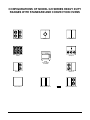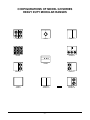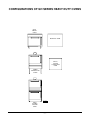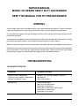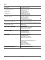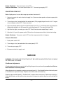
1
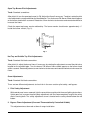
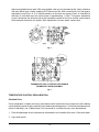
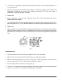
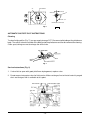
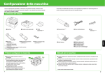
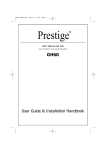
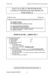
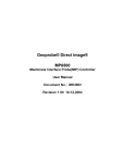
SERVICE MANUAL
GH SERIES HEAVY DUTY GAS RANGES
MODELS
GH30
GH45
GH53/72
GH56
GH60
GH60T
GH70
GH72/45
GH45/72
GH60/45
GH60T45
GH60/72
GH60T72
GHM30
GHM45
GHM5372
GHM56
GHM60
GHM60T
GHM72
GHM7245
GHM4572
GHM6045
GHM60T/45
GHM6072
GHM60T/72
GHX45
GHX60
GHX60T
GHXM45
GHXM60
GHMX60T
GHX72
GHXM72
ML-52141
ML-52142
ML-52173
ML-52143
ML-52144
ML-52171
ML-52145
ML-52176
ML-52180
ML-52174
ML-52186
ML-52175
ML-52188
ML-52151
ML-52152
ML-52195
ML-52153
ML-52154
ML-52172
ML-52155
ML-52179
ML-52181
ML-52177
ML-52187
ML-52178
ML-52189
ML-52217
ML-52218
ML-52223
ML-52220
ML-52221
ML-52224
ML-52219
ML-52222
VULCAN-HART COMPANY, P.O. BOX 696, LOUISVILLE, KY 40201- 0696, TEL. (502) 778-2791
FORM 30848 Rev. A (9-98)
IMPORTANT FOR YOUR SAFETY
THIS MANUAL HAS BEEN PREPARED FOR PERSONNEL QUALIFIED TO INSTALL GAS
EQUIPMENT, WHO SHOULD PERFORM THE INITIAL FIELD START-UP AND
ADJUSTMENTS OF THE EQUIPMENT COVERED BY THIS MANUAL.
POST IN A PROMINENT LOCATION THE INSTRUCTIONS TO BE FOLLOWED IN THE
EVENT THE SMELL OF GAS IS DETECTED. THIS INFORMATION CAN BE OBTAINED
FROM THE LOCAL GAS SUPPLIER.
IMPORTANT
IN THE EVENT A GAS ODOR IS DETECTED, SHUT
DOWN UNITS AT MAIN SHUTOFF VALVE AND
CONTACT THE LOCAL GAS COMPANY OR GAS
SUPPLIER FOR SERVICE.
FOR YOUR SAFETY
DO NOT STORE OR USE GASOLINE OR OTHER
FLAMMABLE VAPORS OR LIQUIDS IN THE
VICINITY OF THIS OR ANY OTHER APPLIANCE.
WARNING
IMPROPER INSTALLATION, ADJUSTMENT,
ALTERATION OR MODIFICATION, SERVICE OR
MAINTENANCE CAN CAUSE PROPERTY
DAMAGE, INJURY OR DEATH. READ THE
INSTALLATION, OPERATING AND MAINTENANCE
INSTRUCTIONS THOROUGHLY BEFORE
INSTALLING OR SERVICING THIS EQUIPMENT.
IN THE EVENT OF A POWER FAILURE, DO NOT
ATTEMPT TO OPERATE THIS DEVICE.
-2-
TABLE OF CONTENTS
PAGE
CONFIGURATIONS OF MODEL GH SERIES HEAVY DUTY RANGES . . . . . . . . . . . . . . . . . . . . 4
GENERAL. . . . . . . . . . . . . . . . . . . . . . . . . . . . . . . . . . . . . . . . . . . . . . . . . . . . . . . . . . . . . . . . . . . . . . 8
TROUBLESHOOTING . . . . . . . . . . . . . . . . . . . . . . . . . . . . . . . . . . . . . . . . . . . . . . . . . . . . . . . . . . . . 8
LIGHTING AND SHUTTING DOWN PILOTS . . . . . . . . . . . . . . . . . . . . . . . . . . . . . . . . . . . . . . . . . 10
Open Top, Griddle Top and Hot Top Burner Pilots . . . . . . . . . . . . . . . . . . . . . . . . . . . . . . . . . 10
Standard Oven Pilot . . . . . . . . . . . . . . . . . . . . . . . . . . . . . . . . . . . . . . . . . . . . . . . . . . . . . . . . . . 10
Convection Oven Pilot . . . . . . . . . . . . . . . . . . . . . . . . . . . . . . . . . . . . . . . . . . . . . . . . . . . . . . . . 11
SERVICE . . . . . . . . . . . . . . . . . . . . . . . . . . . . . . . . . . . . . . . . . . . . . . . . . . . . . . . . . . . . . . . . . . . . . 11
Pilot Burner Adjustments . . . . . . . . . . . . . . . . . . . . . . . . . . . . . . . . . . . . . . . . . . . . . . . . . . . . . . 11
Open Top Burner Pilot Adjustments . . . . . . . . . . . . . . . . . . . . . . . . . . . . . . . . . . . . . . . . . . . . . 12
Hot Top and Griddle Top Pilot Adjustments . . . . . . . . . . . . . . . . . . . . . . . . . . . . . . . . . . . . . . . 12
Oven Adjustments . . . . . . . . . . . . . . . . . . . . . . . . . . . . . . . . . . . . . . . . . . . . . . . . . . . . . . . . . . . 12
TEMPERATURE CONTROL RECALIBRATION . . . . . . . . . . . . . . . . . . . . . . . . . . . . . . . . . . . . . . 13
Standard Oven . . . . . . . . . . . . . . . . . . . . . . . . . . . . . . . . . . . . . . . . . . . . . . . . . . . . . . . . . . . . . . 13
Convection Oven . . . . . . . . . . . . . . . . . . . . . . . . . . . . . . . . . . . . . . . . . . . . . . . . . . . . . . . . . . . . 14
AUTOMATIC SHUTOFF PILOT INSTRUCTIONS . . . . . . . . . . . . . . . . . . . . . . . . . . . . . . . . . . . . . 15
Cleaning . . . . . . . . . . . . . . . . . . . . . . . . . . . . . . . . . . . . . . . . . . . . . . . . . . . . . . . . . . . . . . . . . . . 15
Service Instructions . . . . . . . . . . . . . . . . . . . . . . . . . . . . . . . . . . . . . . . . . . . . . . . . . . . . . . . . . . 15
Thermostatically Controlled Griddle Recalibration . . . . . . . . . . . . . . . . . . . . . . . . . . . . . . . . . 16
-3-
CONFIGURATIONS OF MODEL GH SERIES HEAVY DUTY
RANGES WITH STANDARD AND CONVECTION OVENS
GH45
GH30
GH72
GH56
GH53/72
GH45
FULL BODY
34" WIDE
GH72/45
GH60/GH60T
GH45/72
GH60/72/GH60T72
-4-
PL-51241
GH60/45/GH60T/45
CONFIGURATIONS OF MODEL GH SERIES
HEAVY DUTY MODULAR RANGES
GHM45
GHM30
GHM72
GHM56
GHM53/72
GHM45
GHM72/45
GHM60
GHM60T
GHM45/72
GHM60/72
GHM60T/72
-5-
PL-51276
GHM60/45
GHM60T/45
CONFIGURATIONS OF MODEL GH SERIES HEAVY DUTY
EXPANDO RANGES
MODEL GHX SERIES EXPANDO RANGES WITH CABINET
GHX45
GHX60
GHX60T
GHX72
GHX45 18" WIDE
FULL BODY WITH
CABINET
MODEL GHXM SERIES MODULAR EXPANDO RANGES
GHXM45
GHXM60
GHXM60T
GHXM72
PL-51242
GHXM45
-6-
CONFIGURATIONS OF GH SERIES HEAVY DUTY OVENS
GHO1
SINGLE
OVEN
WORK TOP VIEW
GHO1C
SINGLE
CONVECTION
OVEN
GHMO1
ON MODULAR
STAND
PL-51243
GHO2
DOUBLE
STACKED
OVEN
-7-
SERVICE MANUAL
MODEL GH SERIES HEAVY DUTY GAS RANGES
KEEP THIS MANUAL FOR FUTURE REFERENCE
GENERAL
Vulcan ranges and ovens are produced with quality workmanship and material. Proper installation,
usage and maintenance of your range will result in many years of satisfactory performance.
The manufacturer suggests that you thoroughly read this entire manual and carefully follow all of the
instructions provided.
A rating plate is located on the lower left-hand corner of the front frame behind the bellcrank. The rating
plate states the model number, serial number and type of gas the range requires.
Motors in Vulcan convection ovens are permanently lubricated and require no additional maintenance.
Should it be necessary to disconnect the gas line strain relief at the rear of the range in order to perform
service procedures, turn off the gas supply before disconnection. Reconnect the strain relief before
turning the gas supply on and returning the range(s) to their installation position.
TROUBLESHOOTING
TOP BURNER OPERATION
PROBLEM
PROBABLE CAUSES
Improper Burner Combustion
Excessive Valve Handle Temperatures
Sticking Top Burner Valves
Improper use, allowing improper ventilation.
Poor door fit.
Oven door left open.
Poor Ignition
Insufficient gas input.
Poor air-to-gas adjustment.
Restriction in pilot orifice.
Restriction in main burner ignition port.
Restriction in control valve.
Restriction in gas orifice.
-8-
OVEN
PROBLEM
PROBABLE CAUSES
Too Much Bottom Heat.
Insufficient heat input.
Overactive flue.
Too low temperature.
Improper operation.
Improper bypass setting
Fluctuating gas pressure.
Uneven Bake
Side Burning
Too Much Top Heat
Too high temperature.
Faulty ventilation.
Excessive heat input.
Thermostat needs calibration.
Uneven Bake - Side to Side
Range not level side to side.
Oven burner, bottom or baffles improperly installed.
Pulling to Edge of Pan
Warped pans.
Oven not level.
Uneven Bake - Front to Rear
Overactive flue.
Range not level front to back.
Door not closing properly.
Dried Out Products
Too low temperature.
Too long baking time.
Thermostat calibration.
Pilot Outage
Gas supply not sufficient.
Pilot flame too low.
Restriction in pilot orifice.
Malfunctioning check valve.
CONVECTION OVEN MODELS ONLY:
Cavity leaking.
Gasket problems.
Snorkel tube blocked.
Blower running backwards.
Excessive Meat Shrinkage
Roasting temperature too high.
-9-
LIGHTING AND SHUTTING DOWN PILOTS
OPEN TOP, GRIDDLE TOP AND HOT TOP BURNER PILOTS
1. Turn main gas supply ON.
2. Turn all top burner valve knobs ON to purge gas line of air.
3. Turn top burner valve knobs OFF.
4. Wait 30 seconds.
5. Using a taper, light the pilot(s).
6. If pilot fails to light, wait 5 minutes and repeat Steps 1 through 5.
7. Turn one top burner valve ON to ensure that all gas lines are completely purged of air. Turn burner
OFF when gas begins to flow.
Nightly Shutdown: Turn burner valve OFF; pilot will remain lit.
Complete Shutdown: Turn burner valve OFF; pilot will remain lit. Turn main gas valve OFF.
STANDARD OVEN PILOT
Before lighting oven, be sure that range top sections have been lit.
1. Open oven door and locate square pilot lighter cutout.
2. Using a taper, light oven pilot by depressing red ignition button (Fig.1) located on the side control
panel above the thermostat knob. Light pilot and continue to hold ignition button in for one minute.
If pilot fails to light, turn main gas valve OFF and wait 5 minutes before repeating Steps 1 and 2.
3. Set oven thermostat to desired temperature.
PL-40052
Fig. 1
- 10 -
Nightly Shutdown: Turn oven burner valve OFF.
Complete Shutdown: Turn oven burner valve OFF. Turn main gas supply OFF.
CONVECTION OVEN PILOT
Before lighting oven, be sure that range top sections have been lit.
1. Connect range to the main electrical supply line. Open oven door panel and locate square pilot
lighter cutout.
2. Turn red gas valve (located behind the control panel) ON, purging the gas line of all air. Turn gas
valve and power switch OFF. Close oven door.
3. Light oven pilot by depressing the red ignition button (see Fig. 1), and using a taper, ignite the pilot.
Hold ignition button in for 30 seconds, or until pilot remains lit. Turn gas valve back ON.
4. If pilot fails to light, turn main gas valve OFF. Wait 5 minutes and repeat Steps 2 and 3.
5. After pilot is lit, push the power switch ON and turn the temperature dial to the desired setting.
Nightly Shutdown: Turn power switch OFF and the temperature dial to 0 degrees.
Complete Shutdown:
1. Push power switch OFF.
2. Turn red gas valve (located behind the control panel) OFF.
3. Turn main gas supply OFF.
4. Disconnect electrical supply cord.
SERVICE
WARNING: THE RANGE AND ITS PARTS ARE HOT. BE CAREFUL WHEN OPERATING, CLEANING
OR SERVICING THE RANGE.
Pilot Burner Adjustments
All adjustment procedures associated with pilot lighting are to be performed by an authorized VulcanHart installation or service person.
After adjustments are complete, replace oven control panel(s). Check identification so that each panel
is returned to its respective range. Replace oven baffles and oven bottom(s).
Replace upper manifold panel(s). Position brick in ranges where necessary. Replace top casting(s).
Check identification so that each may be returned to its respective original range as received from the
factory.
- 11 -
Open Top Burner Pilot Adjustments
Tools: Standard screwdriver.
After pilot is lit, turn the open top burner(s) ON. Adjust the flame if necessary. To adjust, rotate the pilot
valve adjustment screw provided on the manifold pipe. Turn the burner ON; burner flame should appear
on the burner head within a second. Rotate the screw clockwise to decrease and counterclockwise to
increase the flame.
Check the open top burner nozzle relationship. The burner nozzle should enter approximately 1/4"
inside the burner venturi (Fig. 2).
Fig. 2
Hot Top and Griddle Top Pilot Adjustments
Tools: Standard flat blade screwdriver.
After pilot is lit, adjust the burner flame, if necessary, by rotating the adjustment screw of the pilot valve
located on the manifold pipe. Turn the burner ON; burner flame should appear on the burner head
within a second. Rotate adjustment screw clockwise to decrease and counterclockwise to increase the
flame.
Oven Adjustments
Tools: Standard flat blade screwdriver.
There are two different adjustments to check for in the oven section: pilot safety, and bypass.
1. Pilot Safety Adjustment
With control panel cover removed, light the oven pilot as explained in the oven lighting instructions.
If pilot goes out, increase the pilot safety adjustment until the flame completely engulfs the safety
device sensing bulb. The safety adjustment screw is located on the safety control below the red
button.
2. Bypass Flame Adjustment (Oven and Thermostatically Controlled Griddle)
This adjustment must be made at time of range installation.
- 12 -
Ignite oven/griddle burner pilot. With oven/griddle cold, turn the thermostat dial slowly clockwise
until main burner gas is heard snapping ON. Remove the dial. With a screwdriver, turn the bypass
adjustment screw (Fig’s. 3 & 4) counterclockwise to increase the bypass flame, or clockwise to
decrease it, until flame over the entire burner is approximately 1/8" high. The bypass adjustment
screw is located to the left-hand side of the thermostat control for the oven section, and on top of
the thermostat control for the griddle. After adjustment has been made, replace dial.
Fig. 3
THERMOSTATICALLY CONTROLLED GRIDDLE
THERMOSTAT BULB ASSEMBLY
Fig. 4
TEMPERATURE CONTROL RECALIBRATION
Standard Oven
Field recalibration is seldom necessary and should not be resorted to unless experience with cooking
results definitely proves that the control is not maintaining set temperature. To check oven temperatures
when recalibrating, use a Robertshaw Test Instrument or a reliable mercury oven thermometer.
1. Place thermocouple of test instrument or thermometer in the middle of the oven. Close oven door.
2. Light main burner.
- 13 -
3. Turn dial to any temperature setting and allow oven to heat until flame cuts down to bypass. Let
cycle several times.
4. After burner has been on sufficiently long enough to cut down the bypass flame, check oven
temperature. Recalibrate the control if your reading is not within 15°F of the dial setting. If
recalibration is required, proceed as follows:
5. Remove dial.
6. With a screwdriver, loosen the two calibration screws (Fig. 5) until calibration plate moves
independently of the control.
7. Turn calibration plate until mark corresponding to test instrument or thermometer reading is in line
with center of pointer "A" (Fig. 5), and while holding in this position, tighten calibration screws firmly.
8. Replace dial.
9. If above adjustment is prevented by the two loosened calibration screws being in contact with the
ends of the screw clearance slots in the calibration plate, remove the screws, and after turning the
calibration plate to the proper location, reassemble screws in the other tapped holes designed for
them.
Fig. 5
Convection Oven
1. Place thermocouple of test instrument in middle of oven. Close oven door.
2. Light the main burner by turning thermostat dial to any temperature setting.
3. Allow oven to heat until flame cuts off. After several cycles, check temperature. If the temperature
does not read within 15°F of the dial setting, recalibrate as follows:
4. Pull dial straight off dial shaft without turning (Fig. 6).
5. Turn screw "A" clockwise to decrease temperature and counterclockwise to increase temperature
(Fig. 6); 1/4 turn of Screw "A" represents a temperature shift of 35°F.
- 14 -
"A"
DIAL SHAFT
DECREASE
INCREASE
"A"
1/4 TURN = 35º F
THERMOSTAT CALIBRATION
Fig. 6
PL-50119
AUTOMATIC SHUTOFF PILOT INSTRUCTIONS
Cleaning
To clean limiting orifice (Fig. 7), turn gas supply to range OFF. Disconnect pilot tubing at the pilot burner
body. The orifice is then accessible at the body end of the pilot burner and can be removed for cleaning.
Clean spud, taking care not to enlarge the orifice hole.
Fig. 7
Service Instructions (Fig. 8)
1. If valve fails to open with good pilot flame impingement, replace valve.
2. Do not remove interrupter valve for field service. Make certain gas line to inlet of control is purged
of air and that gas flow is available at this point.
Fig. 8
- 15 -
Thermostatically Controlled Griddle Recalibration
Field recalibration is seldom necessary and should not be resorted to unless cooking results definitely
prove that griddle surface temperature and thermostat setting do not agree. To check griddle
temperature, use an accurate "surface temperature thermometer" in the following manner.
1. Locate thermometer in center of griddle from front to rear: on 17" wide units, use one thermometer
and center from side to side; on 34" wide units, use two thermometers, one 81/2" from each side of
the griddle.
2. Set thermostat dial to any temperature and allow griddle to heat thoroughly. When the griddle is
completely heated and the burner is on bypass gas, check the thermometer reading against the
thermostat dial setting. If the difference between the readings exceeds 15°F, the thermostat should
be recalibrated. Example: With the thermostat dial at 400°F and a thermometer reading of less than
385°F or more than 415°F, the thermostat should be recalibrated.
Recalibrate as follows:
1. Make note of number of degrees thermostat is off.
2. Remove thermostat dial and loosen calibration screws (Fig. 9) until plate moves freely.
3. Turn calibration plate the required number of degrees counterclockwise if the thermometer reading
was higher than the dial setting, or clockwise if the thermometer reading was lower than the dial
setting. The number of degrees between letters on the calibration plate is 50°F.
4. Hold calibration plate in desired position and tighten plate screws firmly.
Fig. 9
FORM 30848 Rev. A (9-98)
- 16 -
PRINTED IN U.S.A.