1
PowerCon 4.1
Installation / Operation Manual
PowerCon4_ma_en_rev02.doc
INDEX
Features .........................................................................................................- 4 System requirements .....................................................................................- 4 Software Installation......................................................................................- 5 Program start .................................................................................................- 6 Surface description.........................................................................................- 7 Explorer .....................................................................................................- 7 Menu bar....................................................................................................- 7 General function description...........................................................................- 8 Configuration .............................................................................................- 8 Menu bar / Program ...............................................................................- 8 Menu bar / View .....................................................................................- 8 Menu bar / Edit.......................................................................................- 9 Menu bar / Tool .................................................................................... - 24 Menu bar / System ............................................................................... - 27 User rights management ................................................................... - 33 Application User Rights Management ............................................. - 33 Creating new user .......................................................................... - 33 User rights assignment .................................................................. - 34 Group membership......................................................................... - 35 System Access Rights Management ................................................ - 35 Database maintenance ...................................................................... - 36 Menu bar / Help.................................................................................... - 36 Internet update .................................................................................... - 36 About ................................................................................................... - 36 Getting started .............................................................................................- 37 DVR Setup in 10 steps .............................................................................. - 37 Setup DVR connection........................................................................... - 37 Composition of Graphic User Interface .........................................................- 39 Setup of maps and graphics ..................................................................... - 39 Sample project: Setup of LOCATIONS and AREAS ..................................... - 42 Step 1: Defining LOCATIONS ................................................................. - 43 Step 2: Defining AREAS......................................................................... - 44 Step 3: Defining DVR systems and cameras .......................................... - 47 Step 4: Linking locations, areas, DVRs and cameras in design mode...... - 50 PowerCon 4.1 Operation...............................................................................- 57 Opening video windows ........................................................................... - 57 Live View .............................................................................................. - 58 Record search....................................................................................... - 59 Saving Screenshots............................................................................... - 61 Printing screenshots ............................................................................. - 61 Archiving video files ............................................................................. - 61 Sequence view...................................................................................... - 63 Bug report wizard .................................................................................... - 63 APPENDIX A: BITMAP GRAPHICS FOR ICONS AND BUTTONS .......................- 63 PowerCon 4.1 Alarm Receiver ......................................................................- 63 Alarm Receiver Configuration................................................................... - 63 Bindings: IP settings for the receiver PC ............................................... - 63 PC Operation mode ............................................................................... - 63 Languages ............................................................................................ - 63 Database .............................................................................................. - 63 DVR settings ............................................................................................ - 63 Alarm actions........................................................................................... - 63 Alarm server operation ............................................................................ - 63 Alarm overview........................................................................................ - 63 I/O Controller EPS 100.................................................................................- 63 EPS 100 setup in PowerCon...................................................................... - 63 Setting for visualization in Explorer List .......................................................... - 63 Network alarm setup ................................................................................... - 63 -2-
EPS 100 operation ...................................................................................... - 63 Network Alarm ........................................................................................... - 63 PowerCon 4.1 SystemChecker ......................................................................- 63 General settings....................................................................................... - 63 Configuration of monitored systems......................................................... - 63 Operation................................................................................................. - 63 Network traffic monitor ........................................................................... - 63 EDR 1600 / 400 HDD Player .........................................................................- 63 Operation................................................................................................. - 63 Print images / export images and video streams...................................... - 63 Search recordings .................................................................................... - 63 -
-3-
Features
9
9
9
9
9
9
9
9
9
9
9
9
9
unlimited number of managed systems (DVRs, network cameras)
live and playback view
local storage and printout of video data or single pictures on client PC
multi-window design with scalable video windows
free definable multiviews with up to 4 DVR systems or network cameras, also
mixed display of different DVRs (max. 64 cameras in 1 multiview with 4 x 16channel DVR)
mapview: visualisation of CCTV system in areas or buildings with free scalable
maps / graphics (BMP or JPG format)
remote DVR configuration (EDR DVR series only)
network alarm reception and management
multi-monitor support (depending on PC configuration)
advanced access rights management with individual user rights for functions
and system access
network monitor for visualisation of network traffic
system checker: integrated background port checker with alarm function for
availability of DVRs and cameras in network
support of external program starts
System requirements
Processor:
PC Pentium IV (1.6 or higher)
AMD Athlon (1.8 or higher)
Operating system: Windows XP, service pack 1 or higher
VGA card:
32 MB min., 16,7 million colours, with DirectX 9.0C support
USB:
2.0 interface
Memory:
256 MB RAM
30 MB free HD space for installation
min. 10 MB free HD space for storage
Mediaplayer:
Microsoft mediaplayer version 8.x or higher
Further:
DirectX 9.0C
Supported DVRs:
EDR 400 / 1600*
EDSR 400 H / M*
EDSR 100 / 600 / 900 / 1600*
EDR 410 / 810 H/M
EDR 910 / 920 / 1610 / 1640
* latest DVR firmware version
Supported
network cameras: EAN 600
Versions:
PowerCon 4.1
Single client version with USB key
PowerCon 4.1 Update
Update version for PowerCon Pro and
PowerCon Station (serial number of
existing version required)
-4-
Software Installation
1. Insert the CD-ROM into the CD drive.
2. If autostart function is activated, setup will start automatically by opening internet
explorer. If autostart function is deactivated, choose the CD drive from your
desktop and start the program manually by double-click.
3. If your browser asks to confirm the authorization of active contents, confirm this
dialogue with “YES” to enter the setup dialogue.
4. Select SETUP to start the PowerCon 4.0 software setup.
5. If your browser asks to either save or execute the setup file, confirm with
EXECUTE.
6. If your browser shows a security warning concerning the digital signature, confirm
with EXECUTE.
7. From the pulldown menu, choose the appropriate setup language and follow the
instructions in the dialogue box.
NOTE: Acceptance of the end-user license agreement is compulsory to continue
the setup program!
8. Start PowerCon 4.0 remote software.
-5-
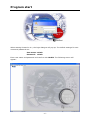
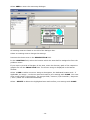
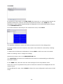
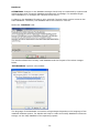
Program start
When starting PowerCon 4.1, the login dialogue will pop up. The default settings for user
name and password are:
User name: admin
Password: admin
Enter user name and password and confirm with LOGIN. The following screen will
appear:
-6-
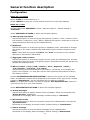
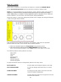
Surface description
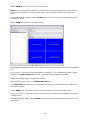
Explorer
The left part of the screen shows the explorer. In case not all listed items are displayed,
the two screen parts may be resized through the vertical line between them. Screen sizes
are saved after logout. The explorer is structured as follows:
- Location ..................... - Area ...................... - Camera .............. - DVR ................... .... - Camera ......... .... - View ............. - I/O Controller...... - Other ................. - Sequences .......... - View .................. - Camera ................... - DVR . ...................... - Camera .............. - View .................. - I/O controller ........... - Other ...................... - Sequences ............... - View ...................... -
general location
areas defined within the location
all cameras installed in this area
all DVRs installed in this area
all cameras connected to the specific DVR
all multiscreen views defined for this DVR
all I/O controllers installed in this area
external single devices installed in this area
all sequences defined in this area
all multiscreen views defined in this area
all cameras installed in the location
all DVRs installed in the location
all cameras connected to the specific DVR
all multiscreen views defined for this DVR
all I/O controllers installed in the location
external single devices installed in the location
all sequences defined in the location
all multiscreen views defined in the location
The group names LOCATION, AREA, CAMERA, DVR, I/O CONTROLLER, OTHER,
SEQUENCES and VIEW are default names and may be modified individually by the
administrator. The administrator also has the possibility to show or hide every single
group in the explorer after configuration.
Menu bar
Program
- close PowerCon 4.1 or logout
View
- define the display options for explorer and system checker
Edit
- add / delete / modify locations, areas, cameras, DVRs, I/O
controllers, sequences, views and external devices and programs
Tool
- start traffic monitor
- start Windows locking utility
System
- set up the system
Help
- start help program, update PowerCon 4.1, display system
information
-7-
General function description
Configuration
Menu bar / Program
Select CLOSE to close PowerCon 4.1.
Select LOGOUT to close the current session and return to the login dialogue.
Menu bar / View
Activate/deactivate EXPLORER to show / hide the explorer – default setting is
“Activated”.
Select EXPLORER OPTIONS to define more display options:
a) Show group description
Activate this option to show the group descriptions (Location / Area / Camera / DVR /
I/O controller / Sequence / View / Other) displayed as explorer. Deactivate to hide the
group descriptions and only list all installed devices
b) Alphasort
Activate this option to arrange the groups in alphabetic order. Deactivate to arrange
the groups in the order Location-Area-DVR-Camera-I/O Controller-Sequence-ViewOther.
Note: if activated, the groups “Location” and “Area” are always on top, whether
Alphasort is activated or deactivated.
c) Aggregate under location
Activate this option to arrange all groups not only under the dedicated area, but also
independent from the areas, arranged by groups. Deactivate to show the groups only
beneath the dedicated area.
d) Show Location / Area / DVR / Camera / View / Sequence / Other /
I/O controller / I/O input / I/O output
Activate each group to be displayed in the explorer. Deactivate to not display the
group in the explorer. You may also use the menu System\Configuration to design
the explorer outlook.
Activate SYSTEMCHECKER NOTIFICATION to observe the process of the installed
DVRs. An additional window will be displayed at the bottom of the right screen. Default
setting is “Deactivated”. Use the horizontal line to resize the window.
NOTE: To enable this function, the add on program “EVF SystemChecker” has to be
executed on any PC in your local network.
Select NOTIFICATION OPTIONS to define more display options:
a) Alarm messages
Activate this option to display network alarm messages, which are forwarded from
"Alarm Receiver" application.
Deactivate to not display alarm messages. Default setting is “Activated”.
b) Successful checks
Activate this option to show all successful checks of all installed DVRs, executed by
"SystemChecker".
Deactivate to not display successful checks. Default setting is “Deactivated”.
c) Status message
Activate this option to show all status messages of the installed DVRs.
Deactivate to not display status messages. Default setting is “Deactivated”.
-8-
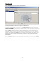
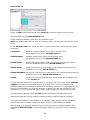
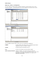
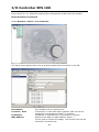
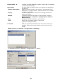
Menu bar / Edit
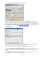
Select Location to enter the location setup dialogue.
All existing locations are listed on the left of the dialogue box.
Choose an existing location to rename it in the DESCRIPTION field and, if applicable,
choose a location image from either the image directory or your local drive. Confirm your
settings with CLOSE.
Select + ADD to add a new location. Assign a description to the new location and, if
applicable, choose a location image from either the image directory or your local drive.
Confirm your settings with CLOSE. Your new location is now listed in the explorer. The
groups Area / DVR / Camera / I/O Controller / Sequence / View / Other are created
automatically.
Select - DELETE to delete the activated location and confirm your settings with CLOSE.
-9-
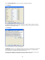
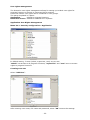
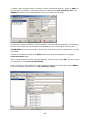
Select AREA to enter the area setup dialogue.
All existing areas are listed on the left of the dialogue box.
Select an existing area to change the settings.
Rename the chosen area in the DESCRIPTION field.
In the LOCATION field, select the location which the area shall be assigned to from the
pulldown menu.
If you want to provide a floorplan of the area, enter the directory path of the respective
graphic file into the IMAGE FILE field. The chosen image is displayed in the bottom
window.
Select + ADD to add a new area. Assign a description, the dedicated location and – if
applicable, an image – to the new area and confirm your settings with CLOSE. Your new
area is now listed in the explorer. The groups DVR / Camera / I/O Controller / Sequence
/ View / Other are created automatically.
Select - DELETE to delete the highlighted area and confirm your settings with CLOSE.
- 10 -
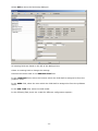
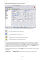
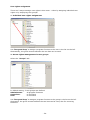
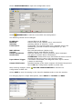
Select DVR to enter the DVR setup dialogue.
All existing DVRs are listed on the left of the dialogue box.
Select an existing DVR to change the settings.
Rename the chosen DVR in the DESCRIPTION field.
In the LOCATION field, select the location which the DVR shall be assigned to from the
pulldown menu.
In the AREA field, select the area which the DVR shall be assigned to from the pulldown
menu.
In the DVR TYPE field, select the DVR model.
In the following field, there are 4 tabs for different configuration options:
- 11 -
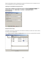
Tab CONNECTION
Enter the host name OR the IP address of the DVR in the HOST field.
Enter the HTTP port, control port and data port numbers as well as the requested timeout
time (msec) in the respective fields.
Enter DVR user name and password.
Tab CAMERA
By selecting a DVR model in the DVR TYPE field, PowerCon 4.1 automatically detects the
maximum number of cameras for this DVR model. The cameras are assigned when
selecting the CAMERA tab. The description is also assigned automatically and depends
on the DVR’s description entered in the DESCRIPTION field.
For further definition and setup of the cameras, select EDIT.
NOTE: Cameras connected to a DVR can only be set up using the DVR setup menu.
There is no possibility to set up a connected camera directly from the explorer!
- 12 -
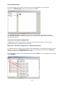
The maximum number of cameras per DVR are listed on the left of the dialogue box.
If not all possible cameras are installed, the surplus cameras should be removed by
choosing DELETE.
If a camera is connected to the DVR after the initial DVR setup, or if a camera has been
deleted by mistake, choose ADD to add a new camera to the DVR.
Select an existing camera to change the settings.
Rename the chosen camera in the DESCRIPTION field.
The LOCATION field cannot be modified as the location is automatically pre-defined by
the DVR’s location.
In the AREA field, select the area in which the camera is installed from the pulldown
menu.
The CAMERA TYPE field is only available when single cameras are configured. When
linked to a DVR, the field cannot be modified, but automatically shows “DVR
connected”.
In the TYPE field, select whether this camera is a static camera or a camera with PTZ
function.
NOTE: It is important to activate PTZ at this stage of configuration, as otherwise the PTZ
control function will not be available during remote sessions!
The linked DVR’s description and IP address are displayed for information. Further
options are only available when single cameras are configured.
Finally, assign a camera number (1~16) to the active camera.
Having defined all cameras, select CLOSE to leave the camera configuration and return
to DVR setup.
- 13 -
Tab VIEW
By selecting a DVR model in the DVR TYPE field, PowerCon 4.1 automatically detects the
possible multiscreen views for this DVR model and lists these in the VIEW tab. The
description is also assigned automatically and depends on the DVR’s description entered
in the DESCRIPTION field.
For further definition and setup of the multiscreen views, select EDIT.
The possible multiscreen views per DVR are listed on the left of the dialogue box.
If not all possible views are required, the surplus views should be removed by choosing
DELETE.
To add further multiscreen combinations, choose ADD to add a new view to the DVR.
Select an existing view to change the settings.
Rename the chosen view in the DESCRIPTION field.
The LOCATION field cannot be modified as the location is automatically pre-defined by
the DVR’s location.
In the AREA field, select the area the view belongs to from the pulldown menu.
Click once into the requested screen part to choose the camera to be displayed from the
context menu.
Having defined all views, select CLOSE to leave the view configuration and return to DVR
setup.
- 14 -
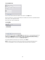
Tab MEMO
PowerCon 4.1 offers this memo page as a pure text area field type which may be used
for further individual information.
- 15 -
DVR remote configuration download / upload
If applicable, select CONFIGURATION to load the configuration of your DVR.
Use the menu bar to open/save/download/upload DVR configuration files.
open configuration file from local drive
save configuration file to local drive
download configuration file from DVR by network
upload configuration file to DVR by network
The available settings correspond with the settings of the machine itself. For detailed
information about the configuration of your DVR, please refer to the device’s manual.
Having finished the DVR configuration, select SAVE to confirm the settings and return to
the DVR setup menu. If you don’t want to confirm the settings, select CANCEL to leave
the DVR configuration and return to the DVR setup menu.
Having defined all DVR settings, select CLOSE to leave the DVR setup and return to the
main menu.
ATTENTION:
PowerCon 4 does not provide motion detection zones for EDR
MPEG-4 series!
- 16 -
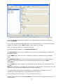
Select CAMERA to enter the camera setup.
All single and DVR-connected cameras are listed on the left of the dialogue box,
irrespective of the sites and areas they’re assigned to.
Select + ADD to add a new single camera.
Select an existing camera to change the settings.
Rename the chosen camera in the DESCRIPTION field.
In the LOCATION field, select the location in which the camera is installed from the
pulldown menu. The LOCATION field is only available when single cameras are set up.
For DVR-connected cameras, the location is pre-defined by the DVR’s location.
In the AREA field, select the area in which the camera is installed from the pulldown
menu.
The CAMERA TYPE field is only available when new cameras are configured. When preconfigured in the DVR setup menu, the field cannot be modified, but automatically shows
“DVR connected”. Select the new camera type:
a) EAN 600
When EAN 600 is selected, the TYPE field is not available. Within the IP-CAM OPTIONS
tab, insert the IP address / host name, user name, password and HTTP port of the EAN
600.
- 17 -
b) DVR-connected
In the TYPE field, select whether this camera is a static camera or a camera with PTZ
function.
NOTE: If your camera does provide PTZ function and has not been chosen as PTZ
camera in the DVR setup, it is important to activate PTZ at this stage of configuration, as
otherwise the PTZ control function will not be available during remote sessions! The
linked DVR’s description and IP address are displayed for information.
c) External
If EXTERNAL is selected, the TYPE field is not available. Within the EXTERNAL tab,
choose SELECT PROGRAM to select the path of the external program. Confirm your
choice with OPEN to transfer the data.
In the PRG PATH field, the program’s path is inserted automatically.
In the PRG NAME field, the program’s file name is inserted automatically.
In the PRG PARAMETER field, enter the external parameters, e.g. the IP address of the
external camera.
- 18 -
Select DELETE to remove a camera from the list.
NOTE: If a DVR-connected camera is removed in the camera setup menu, this camera
can only be re-added in the DVR setup menu, as it’s directly linked to the respective
DVR!
Having defined all cameras, select CLOSE to leave the camera configuration and return
to the main menu.
Select VIEW to enter the view setup menu.
All available multiscreen views of all configured DVRs are listed on the left of the dialogue
box.
In this menu, views can neither be added nor deleted – it is compulsory to add / delete
views in the DVR setup menu, as the views are directly linked to the DVRs.
Select an existing view to change the settings.
Rename the chosen view in the DESCRIPTION field.
The LOCATION field cannot be modified as the location is automatically pre-defined by
the DVR’s location.
In the AREA field, select the area the view belongs to from the pulldown menu.
Click once into the requested screen part to choose the camera to be displayed from the
context menu.
Having defined all views, select CLOSE to leave the view configuration and return to the
main menu.
- 19 -
Select MULTIVIEW to enter the multiview setup.
Select + ADD to add a new multiview and – DELETE to remove an existing multiview
from the list.
Rename the chosen multiview in the DESCRIPTION field.
The LOCATION field cannot be modified as the multiview is automatically assigned to
the location where it is added. Despite this restriction, multiviews can also be created
cross-side.
In the AREA field, select the area the multiview belongs to from the pulldown menu.
Click once into the requested screen part to choose either the camera or the view from
any installed DVR in this location to be displayed from the context menu.
Having defined all multiviews, select CLOSE to leave the multiview configuration and
return to the main menu.
- 20 -
Select SEQUENCES to enter the sequence setup menu.
All available sequences are listed on the left of the dialogue box.
Select + ADD to create a new sequence and - DELETE to remove an existing sequence
from the list.
Select an existing sequence to change the settings.
Rename the chosen sequence in the DESCRIPTION field.
In the LOCATION field, select the location the sequence belongs to from the pulldown
menu.
In the AREA field, select the area the sequence belongs to from the pulldown menu.
Within the SEQUENCE field, highlight the DESCRIPTION line and select + ADD to add
new sequence entries.
Confirm with YES to open the sequence detail editor.
- 21 -
Within the sequence detail editor, choose whether the sequence entry is a single camera,
a view or a multiview. Depending on your choice, the respective cameras, views or
multiviews are available from the pulldown menu – independent of the location, area and
DVR they are assigned to. Select the requested dwell time for this sequence segment by
using the up and down arrows.
After confirming your choice with OK, the sequence entry will be displayed in the
SEQUENCE field.
Having defined all sequences, select CLOSE to leave the sequence configuration and
return to the main menu.
- 22 -
Select OTHER to enter the external programs’ setup.
Next to external cameras, PowerCon 4.1 also offers the possibility to embed the start of
any external program.
All available external programs are listed on the left of the dialogue box.
Select + ADD to add a new external program.
Select - DELETE to remove an external program.
Select an existing program to change the settings.
Rename the chosen program in the DESCRIPTION field.
In the LOCATION field, select the location in which the program shall be placed from the
pulldown menu.
In the AREA field, select the area in which the program shall be placed from the
pulldown menu.
Select SELECT PROGRAM to select the path of the external program. Confirm your
choice with OPEN to transfer the data.
In the PRG PATH field, the program’s path is inserted automatically.
In the PRG NAME field, the program’s file name is inserted automatically.
In the PRG PARAMETER field, enter further parameters, e.g. the IP address or
hostname of a website.
Having added all requested external programs, select CLOSE to exit and return to the
main menu.
NOTE: PowerCon 4.1 enables the start of any external program, but does not support
any further functionality concerning this program. Starting an external program from
PowerCon will create a new screen window and will not affect PowerCon 4.1!
- 23 -
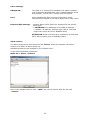
Menu bar / Tool
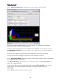
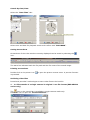
Select TRAFFIC MONITOR to instantly access the network traffic monitor:
With this integrated network traffic monitor, PowerCon 4.1 enables the permanent
observation of the local PC’s network activity.
PowerCon automatically detects the installed network adapters on the local PC. In the
field NETWORK ADAPTER, open the pulldown menu and select the network adapter to
be monitored.
The upper right status bar shows the network adapter’s connection and activity.
The next line shows the adapter’s description, MAC address and speed.
In the FROM LAST RESET field, the start time of the traffic monitor and the time passed
since application start is indicated.
The IN (DOWNLOAD) fields shows the downloading traffic, the OUT (UPLOAD) field
shows the uploading traffic.
To have the traffic monitor permanently visible, activate STAY ON TOP. To move the
traffic monitor into the background, deactivate this option. Default setting is
“Activated”.
Select EXIT to close the network traffic monitor.
- 24 -
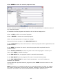
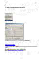
Select WINDOWS LOCKER to enter the Windows lock utility.
Default, the Windows Locker is not available in the menu.
Select System \ Security Configuration \ Application to activate the Windows key
lock and assign the right MENU TOOL -> WINDOWS LOCKER to the
ADMINISTRATOR group:
The changed setting is visible in the TOOL menu:
- 25 -
Use this module to lock certain Windows keys or shortcuts. Activate the checkbox
to activate the Windows locker.
To disable the shortcut Ctrl+Alt+Del, the standard login interface of the WinLogon
process MSGINA (Graphical Identification and Authentification) must be replaced. As
Windows doesn’t use a firm login interface, it can be replaced by a login interface of
another manufacturer. With dGINA, we have developed a login interface which transfers
all commands - besides the shortcut Ctrl+Alt+Del - to the original MSGINA interface.
Activate the CTRL Alt Del checkbox to install the new dGINA login interface
automatically after a security advice. This is a one-time procedure requiring
administrator rights.
Some special features:
Start Button
By activating this checkbox, the Windows START icon can be hidden or shown in the
Windows taskbar. However, the original Windows start menu remains available through
the CTRL+ESC hot key and via the Win keys.
Application key
By activating this checkbox, the application key (Windows menu key) and the hot key
Shift+F10 is disabled.
Desktop
By activating this checkbox, the Windows desktop can be hidden. All desktop icons are
hidden, while the background image remains visible.
Win Keys
By activating this checkbox, the following hot keys are locked:
Win
Win
Win
Win
Win
key:
+ D:
+ E:
+ F:
+ STRG
Win
Win
Win
Win
Win
Win
+
+
+
+
+
+
Show start menu
Minimise or restore all windows
Open Windows Explorer
Show search dialogue
+ F: Show search for computers
F1:
Show help and support centre
R:
Show execute dialogue
Pause: Show system properties
L:
Lock PC
U:
Open help program manager
Q:
Change user
Replace Start Button
This item is effective in combination with „Replace Start Menu“ only.
Replace Start Menu
If activating this checkbox, it is recommended to also lock both the hot key CTRL+ESC
and the WIN keys, as otherwise the original Windows start menu is further available
upon activating these keys.
Select CLOSE to activate the Windows locker settings and to return to PowerCon 4.1.
- 26 -
Menu bar / System
Select either a location or an area from the explorer to enable the DESIGN MODE.
Select System\Design Mode from the menu bar to switch to design mode.
NOTE: It is recommended to set up all locations, areas, cameras, DVRs, I/O controllers,
sequences, views and further required external devices prior to entering the design
mode. Additionally, it is helpful to assign applicable maps or floorplans to the respective
areas in advance. This will ensure the most proper design possibilities.
Select the location / area to be designed by double-click to display the assigned floorplan
/ map in the right screen window.
Place all objects which shall be assigned to this location / area onto the requested
position within the map. There are two ways of placing objects:
1. Move the requested object by “drag & drop” using mouse control
2. Click right into the map and choose EDIT OBJECTS from the context
menu. In the following dialogue, select ADD to add a new object to the map.
The following objects can be placed in the map:
-
other areas
cameras
views
I/O controllers
sequences
external cameras
external programs
By right mouseclick with the mousepointer placed in the map, select
EDIT OBJECTS
to add, delete and configure objects in the map
EXIT DESIGN MODE
to close the design mode and return to normal
mode
HIDE EXPLORER
to enlarge the map view to full screen size and
close the explorer temporarily
SHOW EXPLORER
to scale down the map view to original screen size
and show the explorer
- 27 -
EDIT OBJECTS
Select + ADD to add new objects and - DELETE to remove objects from the area.
Rename objects in the DESCRIPTION field.
Assign objects to another area using the pulldown menu.
NOTE: By selecting a different area, the selected object will be removed from the active
area!
In the ACTION TYPE field, select the action to be initiated when clicking on this object
as follows:
LOCATION
displays another location which can be chosen from
the pulldown menu in the CHANGE SITE tab.
CHANGE AREA
displays another area which can be chosen from
the pulldown menu in the CHANGE AREA tab.
SHOW VIDEO
choose the single camera to be monitored in the remote monitor
from the pulldown menu in the SHOW VIDEO tab.
SHOW VIEW
choose the view to be monitored in the remote monitor from the
pulldown menu in the SHOW VIEW tab.
SHOW SEQUENCE choose the sequence to be monitored in the remote monitor from the
pulldown menu in the SHOW SEQUENCE tab.
OTHER
choose the external program to be started from the pulldown menu
in the OTHER tab.
To optically differentiate the objects placed in the area from each other, select CHANGE
SYMBOL to replace the standard symbol by another icon. There are several icons
available which are automatically added when installing PowerCon 4.1 and which can be
found in the PowerCon 4.1 program directory. If these icons are not suitable for your
application, you may import any other JPEG or BMP graphic file from your local drive.
Having edited all objects, select CLOSE to leave the objects’ configuration menu.
Repeat this procedure for all locations and areas where objects need to be placed.
For further information on the PowerCon 4.1 design mode, please refer to the sample
project described in chapter ”Sample project: Setup of LOCATIONS and AREAS”
After arranging all required objects, open the context menu by right mouseclick and
select EXIT DESIGN MODE to leave the design mode and return to normal operation
mode.
- 28 -
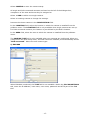
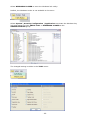
Select CONFIGURATION to enter the system configuration dialogue.
Tab “Explorer”
The standard explorer items are named: Locations / Areas / DVRs / Cameras / Views /
Sequences / I/O Controller / I/O Input / I/O Output / Others. Use this tab to customize
the items to your personal needs.
Tab “Database”
The window shows the currently used database.
ATTENTION: Changes in the database settings should only be conducted by experienced
administrators with enhanced database management knowledge. For standard single
user installations, no changes are required in this menu!
A change in the database file path is only required if several users require access to the
same database. Therefore, the database has to be hosted on a server.
- 29 -
"Edit Database" opens a new window:
The language of the database connection string dialogue depends on the language of the
installed windows system. For details and help to create and modify database connection
strings, use the help database of the operating system.
Tab “Language”
Select one of the program languages available for PowerCon 4.1.
- 30 -
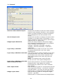
Tab “General”
Autosave video window layout
Activate this checkbox to save the video windows’
positions upon program shutdown. Upon program
restart, all video windows of remote connections
will be displayed at the same position of the
screen.
Auto 4:3 aspect ratio
Activate this checkbox to display all remote video
windows in 4:3 aspect ratio. If activated, it is no
longer possible to resize the remote video window
different from 4:3 aspect ratio.
Image Export Resolution
Select the image resolution with which images
are exported to local directory from the pulldown
menu. Available resolutions are:
176x144 / 352x240 / 352x288 / 640x480 /
720x480 / 720x576 / 800x600 / 1024x768 /
1280x1024.
Login setup / Standard
Select this item to make use of the user names
and passwords defined in the “User rights
management”.
Login setup / Windows username User names can be chosen according to the users’
common Windows user name. With this setting,
the Windows user name will be inserted in the
login screen and the user must only enter his
password.
NOTE: The Windows user name must also
be set up in the “User rights management”.
Login setup / Windows username
without password check
Same setting as above, but without additional
password entry. Login details are verified
automatically by means of the users’ Windows
login details.
Video export folder
Enter the directory path for recorded and archived
video sequences (format: *.avi files for remotely
recorded videos; *.arv files for archived videos).
Default path is: \Folder\Powercon4\Video\Export.
Image export folder
Enter the directory path for saving still images
(format: *.jpg files).
Default path is: \Folder\Powercon4\Image\Export.
- 31 -
“Codec for Remote Recording” opens a new window:
All video codecs installed on the PC are listed under "Compressor". The available
options and settings for framerate, picture size and quality depend on the employed type
of codec. There is no general rule for an optimal setting; this depends amongst others on
the available PC system performance. Comprehensive codec settings guides are available
for download on the DivX homepage www.divx.com/support.
Tab “Notification”
Use the checkboxes to enable / disable alarm sounds for system checks and network
alarms. The default setting for both events is “Enabled”.
If requested, enter a new directory path to any sound file in *.wav format.
The checkbox GRAPHICAL ALARM NOTIFICATION is related to utilisation of the I/O
controller EPS 100. For further information, please refer to the related chapter of this
manual.
Select LAYOUT to either save the current program layout as default setting or to load
the default program layout after changing the layout.
- 32 -
User rights management
The PowerCon user rights management allows for setting up invidual user rights for
program functions or access to connected CCTV systems.
Users with similar user rights can be combined in user groups.
The setup is splitted in 2 parts:
Application:
related to program functions
Restricted access: related to installed CCTV systems
Application User Rights Management
Menu bar > Security configuration > Application
In default setting, 3 users (admin, supervisor, user) are pre-set.
"admin" has access to all program functions, "supervisor" and "user" have no access
rights to program functions.
Creating new user
Select "Add User" :
After entering user name, full name and password, select “OK” to save the settings.
- 33 -
User rights assignment
There are 2 ways to assign user rights in this menu - either by assigning individual user
rights or by employing user groups:
1. Individual user rights assignment:
Use “Drag and drop” to assign a program function to the user in the list on the left.
Alternatively, the green arrows between the two lists can be used.
2. Access rights management in user groups
Select the "Groups" tab:
In default setting, 3 user groups are defined:
Administrator:
all program functions
Supervisor:
no functions
User:
no functions
Use “Drag and drop” to assign a program function to the group in the list on the left.
Alternative, the green arrows between the two lists can be used, also for removing
functions.
- 34 -
Group membership
For working with user groups, all users have to be assigned to a user group.
Select the "Membership" tab to set up group members:
Use “Drag and drop” to assign a user to one of the groups in the list on the left.
Alternatively, the green arrows between the two lists can be used, also for removing
users from a group.
System Access Rights Management
Independently of the user rights for functions, PowerCon provides an access right
management for all installed CCTV systems.
Menu bar > Security configuration > Restricted Access:
In default setting, all users have access to all installations. For blocking access to a view,
camera or area, use “Drag and drop” to move the restricted item from the "Record"
list on the right to the related user on the left.
This restrictions can be set for individual users (tab "Users") or for complete user groups
(tab "Groups").
- 35 -
Database maintenance
Select DATABASE MAINTENANCE to reorganize the database.
Menu bar / Help
Select HELP to enter the online help file.
NOTE: The program ADOBE ACROBAT 7.0 must be installed on your computer to enable
the help file function.
Internet update
Select INTERNET UPDATE to check online for current program updates.
About
Select ABOUT to check the current program version and serial number of PowerCon 4.1.
- 36 -
Getting started
DVR Setup in 10 steps
First step after installing the software is the setup of DVRs and Network cameras which
are to be managed by PowerCon.
Setup DVR connection
From the menu bar, select EDIT > DVRs to enter the DVR setup menu.
1. Select + ADD to create a new DVR system in the database.
2. Confirm "Add new DVR" with "YES".
- 37 -
3. Enter a free DVR system description (this text appears in the explorer and is also used
as default description text for VIEWS and CAMERAS).
4. If PowerCon uses different locations for better overview on the system, select a
location. If this feature is not required, keep the DEFAULT setting. For LOCATION
setup, please refer to chapter “Defining LOCATIONS”.
5. If areas are utilized, assign the DVR system to an AREA. For AREA setup, please refer
to chapter “Defining AREAS”.
6. Select the DVR type. After changing the DVR type, the program will ask "Restore
default Camera and View settings?". Upon confirmation with "YES", the program will
create a list with all VIEWS and CAMERAS available for this DVR type. The created
cameras and views can be edited in the EDIT > CAMERA / EDIT > VIEW menus or
through right mouseclick on the camera / view in the explorer: > EDIT.
"NO" preserves the VIEW AND CAMERA list from the default DVR.
7. Enter the IP address or web address assigned to the DVR.
8. Enter the required ports for IP connection.
Required ports for EverFocus DVR, please check these ports also in your firewall setting:
EDR 1600 (from version 3.1)
EDR 400 (from version 1.3):
EDR 1600/400 versions 2.xx~3.0
(not supported by PowerCon!):
EDSR series:
New EDR series (MPEG4):
Port 80, 1600, 1111
Port 80, 1600, 1024 to 1125
80, 1111, 2222, 3333, 4444, 6666
default ports 80, 1600, 37260
+ 3 following ports
(37261, 37262, 37263)
(ports are editable in EDR network menu)
9. Enter user name and password for network access to the DVR (setup in DVR network
settings).
10. Continue with step (1) to add more DVR systems or select CLOSE to exit DVR setup.
- 38 -
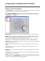
Composition of Graphic User Interface
Setup of maps and graphics
The EXPLORER on the left of the screen contains all installed PowerCon DVR and camera
systems, available maps, graphics and other visualisations.
Select VIEW > EXPLORER to define which items are displayed in the list. If the user
decides to work with maps and graphics only, the list can be switched off by deactivating
> EXPLORER in the VIEW menu.
LOCATIONS: Superordinate level to manage multiple areas, DVRs, cameras and views.
AREAS: areas can be maps, building drawings or photos containing camera and DVR
icons to indicate the location of the CCTV equipment. Live connection to these cameras
and views can be established by simple double-click on the icon.
Areas can be linked among each other. This allows the creation of maps with zoom
function or other functionalities such as “switch to next area” or further visualisations.
CAMERAS: Installed DVR or network cameras. DVR cameras are created automatically if
a DVR is installed in the system.
DVRs: Installed digital recording systems. DVRs can be assigned to both a location and
an area.
I/O Controller: Installed I/O controllers. I/O controllers can be assigned to both a
location and an area.
OTHERS: This function allows the startup of 3rd party software applications installed on
the client PC.
Sequences: Defined sequences. Sequences can be defined independent of the location,
area and DVR they are assigned to.
VIEWS: DVR multiviews. Depending on DVR model, PowerCon provides 4x, 9x and 16x
view. Additionally, also MULTIVIEWS can be defined; up to 4 systems (DVR or network
camera) can simultaneously be displayed in one window.
- 39 -
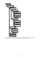
The EXPLORER is structured as follows:
LOCATIONS
DEFAULT LOCATION
AREAS
CAMERAS
DVRs
I/O CONTROLLERS
OTHERS
SEQUENCES
VIEWS
LOCATION
LOCATION
LOCATION
The "DEFAULT LOCATION" is created automatically during installation of the PowerCon
software. All DVRs, cameras, I/O controllers, sequences, views and others not assigned
to specific locations are allocated under the default location.
- 40 -
DVRs, cameras, I/O controllers, sequences, views and others assigned to specific
locations and areas will be listed under these locations and areas.
- 41 -
Sample project: Setup of LOCATIONS and AREAS
The setup of LOCATIONS and AREAS and the assigned video systems should be done in
the following order:
1: LOCATIONS
2: AREAS
3: DVRs, CAMERAS, OTHERS
In order to simplify the setup, the following sample project installation is utilized:
3 installation sites in Europe:
1: 1 x EDR1640 and 3 EAN600 network cameras, located in a factory in Rome
2: 1 x EDR810, installed in EverFocus Europe office, Showroom
3: 1 x EDR410, installed in an office building in Sliema, Malta
The sample project will have the following PowerCon structure:
- 42 -
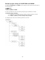
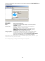
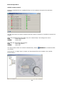
Step 1: Defining LOCATIONS
All 3 installation sites shall be integrated in the location "EUROPE":
MENU BAR > EDIT > LOCATIONS:
Enter the location description (name) and the file path of the image file. For image files,
*bmp and *jpg file formats are supported. Picture size will be adjusted to the window
size available in the program.
ATTENTION: Please consider the aspect ratio of the image file. If working with the
explorer, an aspect ratio of 1:1 is recommended. Without using the explorer, an aspect
ratio of 4:3 is recommended.
After having finished, select CLOSE to leave the location setup. Settings will be saved
automatically.
- 43 -
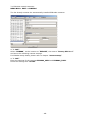
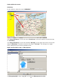
Step 2: Defining AREAS
System 1:
2 x EDR1640 and 3 EAN600 network cameras located in a factory in Rome
MENU BAR > EDIT > AREAS
An area "Italy" is created, assigned to the location "EUROPE".
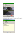
For better visualisation, the CCTV system shall be displayed in a drawing of the factory
site:
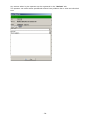
Select "+ Add" and confirm with "YES" to create a new area:
Enter the description, the related location and the file path of the drawing.
- 44 -
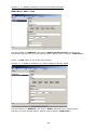
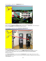
Select "+ Add" again to create the area of the second system:
System 2:
1 x EDR810 installed in EverFocus Europe showroom
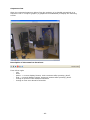
The system shall be visualized with a map of Germany and photos of the installation site:
a) Map of Germany
> "Add":
b) EverFocus building:
> "Add":
- 45 -
c) EverFocus showroom:
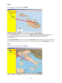
Select "+ Add" again to create the area of the third system:
System 3:
1 x EDR410 installed in an office building in San Gwann, Malta
The videostream of this system shall be displayed by simple click on an icon placed in the
map of Malta.
Finish the area setting with "CLOSE"
- 46 -
All created areas are listed in the EXPLORER:
Step 3: Defining DVR systems and cameras
All required DVRs and network cameras are defined with
MENU BAR > EDIT > DVR
and
MENU BAR > EDIT > CAMERAS
System 1: 1 x EDR1640 and 3 EAN600 network cameras located in X&Y factory in Rome
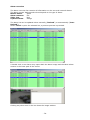
MENU BAR > EDIT > DVR
Set the location to "EUROPE", the area to "FACTORY X&Y s.r.l." and enter the
remaining DVR settings. For DVR settings details, please refer to chapter "DVR Setup ".
- 47 -
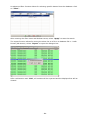
3 x EAN 600 network cameras:
MENU BAR > EDIT > CAMERAS
The list already contains the automatically installed EDR1640 cameras:
> "+ Add"
Select "EAN600", set the location to "EUROPE", the area to "Factory X&Y S.r.l."
and enter the remaining camera settings.
For EAN600 setup details, please refer to chapter "camera setup".
> "+ Add"
Enter the settings for the cameras EAN600_2X&Y and EAN600_3X&Y.
Finish the settings with "CLOSE"
- 48 -
System 2: 1 x EDR810 installed in EverFocus Europe showroom
MENU BAR > EDIT > DVR
Set the location to "EUROPE", the area to "EverFocus Showroom" and enter the
remaining DVR settings. For DVR settings details, please refer to chapter "DVR Setup ".
Select "+ Add" again to set up the third system:
System 3: 1 x EDR410 installed in an office building in Sliema, Malta
Set the location to "EUROPE", the area to "Malta" and enter the remaining DVR
settings. For DVR settings details, please refer to chapter "DVR Setup ".
- 49 -
All required settings are done, all configured systems are listed in the explorer:
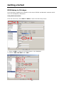
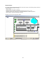
Step 4: Linking locations, areas, DVRs and cameras in design mode
In the DESIGN MODE, all logical links between LOCATIONS, AREAS, DVRs, CAMERAS
and OTHERS can be defined.
The links should be set hierarchically: LOCATIONS > AREAS > DVRs/CAMERAS.
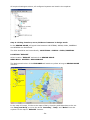
LOCATION "EUROPE"
Select location "EUROPE" and switch to DESIGN MODE:
MENU BAR > SYSTEM > DESIGNMODE
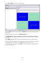
The background colour of the EXPLORER will switch to yellow as long as DESIGN MODE
is active.
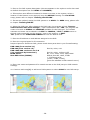
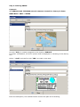
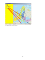
In the map of Europe, 3 links to the maps of Italy, Germany and Malta have to be set.
Use “Drag and Drop” to move the areas "Germany", "Italy" and "Malta" from the
explorer to the map of "EUROPE" location.
- 50 -
The default icon is a blue arrow.
- 51 -
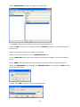
Change the settings by right mouseclick in the map and selecting > EDIT OBJECTS from
the context menu.
Menu items:
Description:
Area:
Action Type:
Change Symbol:
Name of the selected icon
Current area (in this example empty, as currently location
"EUROPE" is active.
Reaction to double-click of the button during operation:
Location: changes to another location
Show Video: opens a video window with single camera
Other: opens defined application on client PC
Change Area: switches to another area (map, graphic)
Show view: opens a multiple camera view
The icon can be changed to any other *.bmp format graphic.
A small library of arrows and symbols is available in the
PowerCon4 program folder, path: PowerCon4\Image\Button
please refer to “Appendix A” for a screenshot catalogue.
Depending on the selected action type, the available options (areas, cameras....) are
activated in the lower part of the menu.
In our sample project, a change of the settings is not required.
- 52 -
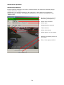
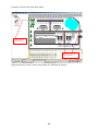
Links within the areas:
Germany:
In the explorer, select the area "GERMANY":
Use “Drag and Drop" to move the area "EverFocus" from the explorer to the area map
of "Germany".
Use “Drag and Drop” to move the location “Europe” to the upper left corner of the area
map of “Germany” in order to return to the map of “Europe”. For linking to an upper
level, change the icon into an upwards arrow:
Right mouseclick in map > Edit Objects:
> Change Symbol: select “up_32” in the folder Bitmap\arrow\color.
- 53 -
In the explorer, select the "EVERFOCUS" area:
Place icons for "EverFocus Showroom" and the map of "Germany" (for returning to
the area “Germany”) and change the type of arrow.
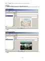
In the explorer, select the area "EverFocus Showroom":
Use "Drag and Drop" to move the view "EDR810-Emmerich-9-View" from the
explorer to the map (listed under \Areas\EverFocus Showroom\DVRs\EDR810Emmerich\Views\...)
Use “Drag and Drop” to move the area “EverFocus” to the upper left corner of the
showroom picture in order to return to the EverFocus building. Change the arrow type in
"Edit Objects" menu.
- 54 -
Malta
In the explorer, select the area "Malta":
Use "Drag and Drop" to move the View "EDR410-Malta San Gwann-4-View" from
the explorer to the map (listed under \Areas\Malta\DVRs\ EDR410-Malta San
Gwann\Views\...).
Use “Drag and Drop” to move the location “Europe” to the upper left corner of the map
in order to return to the map of Europe. Change the arrow type in "Edit Objects" menu.
Italy:
In the explorer, select the area "Italy":
- 55 -
Use "Drag and Drop" to move the area "Factory X&Y" from the explorer to the map.
Use “Drag and Drop” to move the location “Europe” to the upper left corner of the map
in order to return to the map of Europe. Change the arrow type in "Edit Objects" menu.
In the explorer, select the area "Factory X&Y S.r.l.":
Place the icons for the installed cameras or multiple camera views into the area map. The
icons can be changed with right mouseclick in the area map > Edit Objects.
A small library of arrows and symbols is available in the PowerCon4 program folder,
path: PowerCon4\Image\Button. Please refer to “Appendix A” for a screenshot
catalogue.
After these settings, the sample project is finished. Exit the design mode by right
mouseclick in the map and select > EXIT DESIGNMODE, or select “Deactivate” in the
Menu bar > SYSTEM > Designmode
The explorer background colour will change to white again.
- 56 -
PowerCon 4.1 Operation
Opening video windows
Open the requested video window either from the explorer or by double mouseclick on a
video window icon in a map or graphic (if graphics are established):
- 57 -
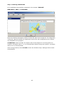
Live View
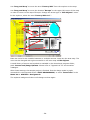
The screenshot shows a 4 x view of an EDR810 DVR:
Title
Video Header
Control Panel
Statusbar
Setup display
Click right into the video window to open the context menu:
Activate or deactivate the display items.
ATTENTION: The "Show title" option is available for EDR400/1600 and EAN600 only!
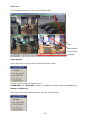
Switch to fullscreen:
Click right on the requested camera to open the context menu:
- 58 -
Switch back to camera multiview:
Click right into the full screen view to open the context menu:
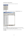
Record search
Select the
icon at the control panel to open the "Playback Selector" menu:
Search by event:
Under the “Segment” tab, the available hard disks and the event list are provided.
The event list offers a filter for motion, alarm contact and video loss events. To use the
filter function, activate / deactivate the specific checkboxes.
For playback, select the hard disk and an entry from the event list and select
"PLAYBACK".
- 59 -
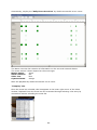
Alternatively, display the "Daily Event Overview" by double mouseclick on an event:
The alarm overview list contains all information on the occurred network alarms.
The event entries’ colours depend on the event type:
Motion alarm:
green
Alarm contacts:
red
Video loss:
blue
System alarms:
orange
Start the playback by double mouseclick on an event.
"Fastplay" List
Once the event list is loaded, this list appears in the lower right corner of the video
window. Playback from this event list can be started through selecting a list entry by
mouseclick without reloading the event list.
- 60 -
Search by time/date:
Select the "Date Time" tab:
Select time and date for playback search and confirm with "PLAYBACK".
Saving Screenshots
Screenshots of the video window currently displayed can be saved by selecting the
icon.
The staus bar indicates both the file path and the file name of the stored image.
Printing screenshots
Double-click on the printer icon
is provided.
to open the printer context menu. A preview function
Archiving video files
PowerCon4 provides 2 technologies to save video files at the local PC:
1. 1:1 file transfer of a single camera in original *.arv file format (EDR MPEG4
series only)
icon in the control bar is available in single camera mode only.
The
Select the icon to open the "Archive Selector":
- 61 -
Select the hard disk and enter start and end time. Select "Archive" to start the file
transfer. The video data will be transferred from the DVR in original quality and frame
rate. Playing back *.arv-files requires the "DVR Viewer" program (provided in PowerCon
program group)
2.
Saving of complete displayed video window
In this mode, the complete videoscreen content is saved to a video file on the PC. This
allows also for saving camera multiviews in one videofile.
The file format depends on the utilized codec. To select the codec and adjust the related
settings, click right into the video window to open the context menu:
Select “Set Remote record” to display the codec options:
All video codecs installed on the PC are listed under "Compressor".
The available options and settings for framerate, picture size and quality depend on the
employed type of codec. There is no general rule for an optimal setting; this depends
amongst others on the available PC system performance.
Comprehensive codec settings guides are available for download on the DivX homepage
www.divx.com/support.
To start recording, select the
progress:
icon in the control bar. The status bar indicates the
If the number of "Skipped Frames" is too high, the settings of the codec should be
modified to a lower resolution or frame rate. In this case, the PC performance does not
comply with the codec settings.
- 62 -
Sequence view
Open the requested sequence either from the explorer or by double mouseclick on a
sequence icon in a map or graphic (if graphics are established) to display the following
screen:
Description of the menu bar functions:
From left to right:
- exit
- start
- pause -> current display freezes, clock continues after pressing „Start“
- stop -> currend display freezes, sequence restarts after pressing „Start“
- change to previous view ahead of schedule
- change to next view ahead of schedule
- 63 -
Bug report wizard
In the unlikely event of a program error, PowerCon 4.1 will automatically create a bug
report which is sent via e-mail to our technical support centre. We kindly ask you to
make use of the bug report wizard in order to support our efforts in continuously
improving PowerCon 4.1.
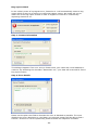
Step 1: Contact information
This dialogue appears if an error occurs. Please enter your name and e-mail address to
continue. By activating the checkbox “Remember me”, your data will be stored for future
bug report events.
Step 2: Error details
Please use the plain text field to describe the error as detailed as possible. The more
detailed your error description is, the faster our technical support will be able to find a
solution. If the error can be reproduced, please activate the respective checkbox.
- 64 -
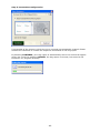
Step 3: Screenshot configuration
A screenshot of the screen in which the error occurred is automatically created. Please
activate the checkbox to include the respective screenshot to the bug report.
By selecting CONTINUE, your bug report is automatically sent to our technical support
centre via e-mail. By selecting CANCEL, the bug report is not sent, but stored in the
PowerCon 4.1 program directory.
- 65 -
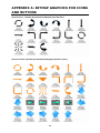
APPENDIX A: BITMAP GRAPHICS FOR ICONS
AND BUTTONS
Arrows b/w (Folder\PowerCon4\Images\Arrows\bw)
Arrows colour (Folder\PowerCon4\Images\Arrows\color)
- 66 -
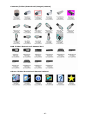
Cameras (Folder\PowerCon4\Images\camera)
DVR (Folder\PowerCon4\Images\dvr)
Others (Folder\PowerCon4\Images\Others)
- 67 -
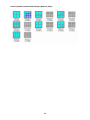
Views (Folder\PowerCon4\Image\Button\View)
- 68 -
PowerCon 4.1 Alarm Receiver
The PowerCon4 alarm receiver allows the receipt of DVR network alarm and works
independently of the PowerCon main program. Optionally, network alarms can be
distributed to other client PCs.
Features:
- popup window with alarm picture, manual "LIVE" switch, alarm action
plan
- alarm log with alarm pictures and filter function
- export function of alarm listing
- alarm forwarding via network alarm to other PC or via email
The alarm receiver is installed together with the PowerCon program. The alarm receiver
application starts either automatically upon PC start (checkbox for AUTOSTART in
installation menu) or manually (START > PROGRAMS > EVERFOCUS > POWERCON4
> ALARM RECEIVER).
The program will start minimized, the alarm receiver icon is visible in the taskbar:
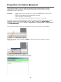
Select the taskbar icon and select “OPEN” in the context menu for alarm receiver
configuration.
The application will open the following window:
- 69 -
The menu bar contains following items:
Alarm:
> Overview: alarm log with all network alarm entries
> Configuration: setup for DVR systems with network alarm transmission
> Action: definition of alarm actions or instructions, which can be assigned
to network alarms
General:
> Configuration: global alarm receiver settings for Language,
IP parameters
HELP:
> Manual: this document
> program and version information
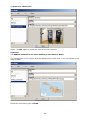
Alarm Receiver Configuration
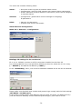
Menu bar > General > Configuration:
Bindings: IP settings for the receiver PC
IP: 0.0.0.0 (default) receives on all IP connections installed on the client PC
For receiving alarms only via a specific IP address at client PC, delete the 0.0.0.0 entry
(" - DELETE") and add the IP address ("+ADD").
In the "Add Binding" menu, one of the IP addresses available at the PC can be selected.
Please make sure that both port number and protocol type comply with the DVR settings
(NETWORK > ALARM menu).
If the system contains DVRs with different protocol types and ports, an additional entry
(with the same IP address) and the different protocol type / port need to be set.
- 70 -
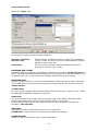
PC Operation mode
Select the "Other" tab
In this menu, the PC operation mode is defined:
Receiver and Client:
Receiver only:
Client only:
default setting, standard setting for single user installation
"server" mode, the PC only receives and distributes network
alarms to other client PCs
PC only receives network alarms distributed by servers
working in "Receiver only" mode
RECEIVER AND CLIENT
Standard mode for single user installations. Activate the checkbox "Notify Powercon" if
alarm messages shall additionally be displayed in the PowerCon notification window. The
IP address 127.0.0.1 is the local host IP address and should not be changed.
RECEIVER ONLY
"Server" mode, the PC only receives and distributes network alarms to other client PCs.
The IP addresses of the client PCs receiving the network alarms are entered in the list
"Alarm Clients".
CLIENT ONLY
PC only receives network alarms distributed by servers working in "Receiver only" mode.
No additional IP address settings are required.
PROTOCOL
The protocol type must comply with the protocol type of the alarm transmitter DVR.
Alarm transmission from server to client always works in UDP mode.
If the system contains DVRs with different protocol types and ports, activate the
checkbox “TCP and UDP”.
UDP PORT
UDP ports for alarm transmission from server to client PCs.
ATTENTION: These ports are not related to the DVR port settings
ALARM SOUND:
Select a *.wav format sound file for alarm notification
- 71 -
MAX. SIMULTANEOUS ALARM POPUPS:
If the system uses alarm popup windows, each window will open a separate ActiveX
application, requiring high resources from the Windows swap file.
Depending on the PC performance, an error could occur after opening too many popup
windows (10~50, depending on PC). Therefore, the number of maximum open alarm
windows can be limited here. Default value is 10.
Upon reaching the maximum number of alarm windows, an alert message appears on the
screen:
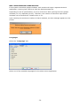
Languages
Select the "Language" tab:
Select one of the available languages for the alarm server application.
- 72 -
Database
ATTENTION: Changes in the database settings should only be conducted by experienced
administrators with enhanced database management knowledge. For standard single
user installations, no changes are required in this menu!
A change in the database file path is only required if several users require access to the
same database. Therefore, the database has to be hosted on a server.
Select the "Database" tab:
The window shows the currently used database and the file path of the alarm images
folder.
"Edit Database" opens a new window:
The language of the database connection string dialogue depends on the language of the
installed windows system. For details and help to create and modify database connection
strings, use the help database of the operating system.
- 73 -
DVR settings
Menu bar > Alarm > Configuration
The list contains all DVR systems installed in Powercon. DVRs must be set up in the
PowerCon program - new DVR systems can not be installed in the alarm server menu.
For all available network alarm events, there are checkboxes available for:
POPUP:
a popup window with alarm picture will appear upon alarms
triggered by motion and alarm contacts
Sound:
an alarm sound is activated at the PC
Log :
an entry in the alarm event list will be created
Alarm output preselection: related to "POPUP". The popup window provides the
possibility to manually switch a predefined output relay if live
connection to the DVR is established. The relay can be
specified in this column.
- 74 -
Other settings:
UNIQUE ID:
The input of a Unique ID is mandatory for alarm reception
(not for EDR400 and EDR1600, item is deactivated for these
DVR models). The ID has to comply with the DVR ID.
todo:
freely editable text field for alarm instructions, these
instructions will appear in the alarm popup menu (tab "todo")
Required DVR settings:
- network alarm option has to be activated for the specific
alarm type
- in NETWORK menu additional to the EDR IP settings:
> ALARM > IP address, protocol type (UDP or TCP) and
unique ID (unique ID not for EDR400/1600)
ATTENTION: Setup of Unique ID is mandatory for DVR and
alarm server setting (not for EDR400/1600)!
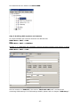
Alarm actions
The alarm popup menu also contains a tab "Action" where the operator can define
actions to be taken as alarm follow-up.
Standard procedures are available in a pull-down menu.
To pre-define standard procedures:
Menu bar > Alarm > Actions:
Enter more standard actions with "+Add" and remove actions from the list with
"-Delete”.
- 75 -
Alarm server operation
Alarm Popup Window
If alarm popup is defined in the menu, network alarms will create an automatic popup
window on the PC screen.
Additionally, the window contains an alarm picture in case alarms are triggered by
motion or alarm contacts. The operator can switch to live video by mouseclick on the
"Live" button.
Number of alarm in log list
DVR title ("Description")
Alarm time and date
Alarm type
Assigned alarm camera
Taken actions
Alarm instructions
Alarm picture or live picture
Switch from alarm picture to
live mode
Exit / close popup window
- 76 -
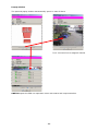
Click the "Live" button to switch from static alarm picture to live mode:
In live mode, the additional "Switch" button allows for switching a DVR output relay if
this is defined in the alarm server DVR setup.
Alarm instructions related to this alarm are displayed by clicking the "todo" tab.
- 77 -
Any actions taken by the operator can be registered in the "Actions" tab.
The operator can either select predefined actions from pulldown list or write an individual
text.
- 78 -
Alarm overview
The alarm overview list contains all information on the occurred network alarms.
The alarm entries’ background colours depend on the type of alarm:
Motion alarm:
green
Alarm contacts:
red
Video loss:
blue
System alarms:
orange
The alarm list can be updated either manually ("Refresh") or automatically ("Auto
Refresh").
Select "Print" to print the selected list; a printout preview is provided.
A double-click on an alarm entry opens both the alarm image and the taken alarm
actions in the lower part of the screen.
Clicking any other item in the list closes the image window.
- 79 -
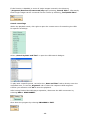
An advanced filter function allows for selecting specific alarms from the database. Click
on "Filter":
After entering the filter items and Boolean terms, select "Apply" to start the search.
The export function allows for saving the alarm list to a file in a database file in *.mdb
format (MS Access). Select "Export" to open the dialogue box:
After confirmation with "YES", all list data will be exported and the displayed list will be
cleared.
- 80 -
I/O Controller EPS 100
From version 4.1 on, PowerCon supports the management of EPS 100 I/O controller.
EPS 100 setup in PowerCon
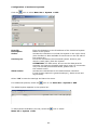
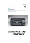
Select Menubar > EDIT > I/O Controller:
The setup menu appears with a list of already installed I/O controllers on the left:
Description:
Location / Area:
IP Address:
MAC Address
Free editable title of controller box
If PowerCon is used with maps/ graphics, EPS-100 can be
assigned to requested areas and / or locations.
IP-address or web address (if connected via internet)
Display of the EPS 100 MAC address. Select "..."
on the right to refresh this display. This function can also be
used as a connection test.
- 81 -
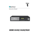
To add an I/O controller which is located in same LAN as the client PC, select + ADD. All
I/O controllers available in the LAN network are listed in the I/O Controller List. This
SEARCH function works independently of the PC or EPS 100 IP range:
For the basic network settings, enter IP address, subnet mask and gateway. If necessary,
also the control port can be changed (if standard port 23 is blocked by firewall, ISP...).
ATTENTION: Do not use port 99 in this setting. Port 99 is used for configuration up- and
download!
Confirm the network settings with APPLY and enter a short description in the I/O
Controller Name field.
After having entered the basic network settings, close the menu with OK. The new values
are resumed in the I/O Controller Setup.
If the controller is not installed in a LAN network (connected via Internet), select NEW to
enter the settings manually in the I/O Controller Setup.
- 82 -
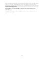
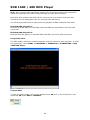
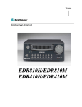
Select CONFIGURATION to open the configuration menu:
Select
DOWNLOAD to load the current EPS 100 configuration.
The following values can be changed:
IP address:
Netmask:
Gateway:
Control port:
MAC address:
Version:
Out-IP IP address:
Out-IP Port:
Input Alarm Trigger:
Output initial state:
internal EPS 100 IP address
subnet mask of the LAN EPS 100 is connected to
gateway address of network / router
normal EPS 100 communication port, standard value is 23.
Additionally, port 99 is used for configuration up- and
download
EPS 100 MAC address (display only)
display of hard- and software version
client PC address for receiving network alarm messages
TCP port for network alarm transmission
ATTENTION: Please make sure that PowerCon alarm receiver
monitoring this port is set to TCP receiving mode!
if checkbox is activated, the assigned switch input is active
(reacts on switching).
Standard setting of the switch outputs. All checked outputs are
set to ON after configuration upload or power loss.
After entering changes, select
configuration to EPS-100.
UPLOAD CONFIGURATION to transfer the
Select SAVE to save this setting in the client PC database and to close the window.
For changing input or output descriptions, select INPUT or OUTPUT and EDIT:
- 83 -
Both the description and the assignment to areas and locations can be changed, as well
as the assignment to the contact inputs/outputs.
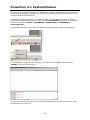
Setting for visualization in Explorer List
Input contacts of EPS-100 can change the colour of assigned areas and cameras in the
explorer list. To enable this function, activate the checkbox GRAPHICAL ALARM
NOTIFICATION under MENU BAR > SYSTEM > CONFIGURATION >
NOTIFICATION.
Network alarm setup
If the EPS 100 setup is configured in the PowerCon software, the EPS 100 is also listed in
the alarm receiver application.
Select Alarm receiver>Alarm>Configuration and choose the requested I/O controller.
- 84 -
Unique Alarm ID:
Input table:
Camera description:
Popup:
Sound:
Log:
Todo:
TCP mode:
The EPS 100 MAC address is used for unique ID. The address
is entered automatically.
For each EPS 100 switch input, the reaction can individually
be defined:
Select a camera linked to this contact. This camera will be
displayed in a popup window, and the camera icon will flash
in maps or graphics.
An alarm popup window with alarm message and further
options will open.
The alarm sound file will open in case of alarm (setup in
Alarm Receiver > General > Configuration > Other >
Alarm sound )
A log entry will be created in case of alarm.
Action list with alarm reaction instructions
(appears in popup window)
EPS 100 generally sends alarms in TCP mode, UDP is not
possible. Make sure that the alarm receiver is set to TCP
mode:
Alarm receiver > General > Configuration > Bindings:
and Alarm receiver > General > Configuration > Other:
- 85 -
EPS 100 operation
Switch output control
Selecting (doubleclick) an installed I/O box in the explorer list opens the operation
window:
The left list shows the switch outputs and their status. Activate a checkbox to switch the
output.
After acknowledgement from EPS 100, the "status lamp" will change the colour:
RED:
output ON (active)
GREEN:
output OFF
The right list shows the input status:
RED:
input ON (active)
GREEN:
input OFF
The input status does not refresh automatically. Select
100 status.
REFRESH to reload the EPS
Alternatively, a single input / output can be selected from the explorer list (similar
functionality):
- 86 -
Network Alarm
If network alarm is programmed for EPS 100 switch inputs, the following alarm reactions
are possible (depending on setting):
- alarm sound
- popup window with alarm message
- assigned area in explorer list will change background colour to red
- assigned cameras are framed by a red flashing border in maps or graphics
- alarm listing in optional notification window
Example: Screen with map before alarm
- 87 -
Example: Screen with map after alarm
Area with red
background
Cameras with red
flashing frame
Right mouseclick on any alarm item allows for resetting all alarms.
- 88 -
Popup window
The optional popup window automatically opens in case of alarm
"Live" connects live to assigned camera
SWITCH opens the EPS 100 operation menu with status and output switches.
- 89 -
PowerCon 4.1 SystemChecker
The PowerCon 4 SystemChecker is an application working independently from PowerCon.
Acting as a "Watchdog", it checks the network availability of connected DVR systems by
cyclic portscan of defined DVRs.
The SystemChecker application is installed together with the PowerCon program and
starts either automatically upon PC start (activate AUTOSTART checkbox in installation
menu) or manually (START > PROGRAMS > EVERFOCUS > POWERCON4 >
SystemChecker).
The program will start minimized; the SystemChecker Icon is visible in the taskbar:
For configuration of the SystemChecker, click right on the taskbar icon and select
"SHOW" from the context menu:
The window is divided in 2 parts: the upper part contains the system list and the lower
part displays the event list.
- 90 -
General settings
Open the configuration menu with the icon
Menu bar > Settings > Configuration:
or select
Tab "Language":
Select one of the supported program languages.
Tab "General"
Cycletime in seconds:
Response Timeout:
Alarm sound:
Notify PowerCon4:
Enter the interval time between the system checks.
Enter the maximum accepted response time of the
connected system during scan.
In case of alarm (connected system not available in
network), a sound can be activated.
Select a sound file in *. wav format.
If this checkbox is activated, an alarm will be forwarded
to PowerCon. The alarm appears in the PowerCon
notification panel.
For forwarding to PowerCon, an IP address and UDP port
input is required. Default settings are 127.0.0.1 (local
host) and port 5050.
For standard single user installation, no changes have to
be done here.
- 91 -
Tab "Email"
For forwarding an alarm message via e-mail, the following entries are required:
SMTP server:
From address:
Recipients:
Send Mail server of the email sender
If the Server requires authentification with user name
and password, activate the checkbox and enter
user name and password.
E-mail address of sender
E-mail address(es) of mail recipient(s),
When entering multiple addresses, separate
addresses by semicolon.
Select "OK" to save the settings and leave the menu.
- 92 -
Configuration of monitored systems
Click the
icon or select Menu bar > System > Add:
Host/IP:
Description:
Active:
Service port:
Alarm action:
Enter the hostname or the IP address of the monitored system
Name of the system
Activate the checkbox to include this system in the cyclic check
(this checkbox is also available for each item on the left side of
the system list)
Port to be checked at the monitored system. Select a port
which is used (open) from the system.
ATTENTION: For EDR series, do not use the data ports for
scanning, as these are dynamic and active upon live connection
only! For utilized ports at EDR DVRs, please refer to
the network menu.
Activate the checkboxes for the desired alarm reactions:
E-mail (setup required in general settings!), alarm sound and
log list entry.
Select "OK" to save the settings and leave the menu.
For additional systems, select the
icon or use Menu bar > System > Add:
The added system appears in the system list:
To edit systems available in the list, select the
Menu bar > System > Edit.
- 93 -
icon or select
Operation
For starting the SystemChecker, select Menu bar > Settings > Cycle active:
The results of the checks are displayed in the event list in the lower part of the window:
To display the log file of application activities, select the
Menu bar > Log > Show:
item or select
Network traffic monitor
To open the Network Traffic Monitor, select the
Menu bar > Tools > Traffic monitor.
icon or select
For further description, please refer to chapter “Menu bar / Tool”.
- 94 -
EDR 1600 / 400 HDD Player
Note: When working with hard disks, please refer to the EDR system’s documentation
containing important information about damage and data loss avoidance.
EDR 1600 /400 system hard disks can be connected to a normal PC, and hard disk
recordings can be played back with the external hard disk player.
The following accessories are required for the playback of EDR 1600/400 hard disks:
EPS-EDR HDD Playerkit 1:
External hard disk player to read EDR-1600 and EDR-400 hard disks via the PC USB
connection
EPS-EDA HDD Playerkit 2:
External hard disk player to read EDA-800 hard disks via the PC USB connection
Programme start
The HDD reader software is installed together with the PowerCon main program. To start
the application, select START > PROGRAMS > EVERFOCUS > POWERCON4 > EDR
1600 HDD Player.
Connect HDD
To open the HDD reader, click on the displayed text OR click on the red button in the
status bar OR select HDD > CONNECT.
- 95 -
Operation
HDD playback is controlled through the buttons at the bottom screen margin in the same
way as the playback of recordings of a connected, distant EDR 1600/400 system.
Playback control
After selecting one or several cameras for playback from the main screen, the playback
control buttons are displayed at the bottom screen margin.
All selected cameras are controlled simultaneously:
Stop
Playback (forward)
Single frame playback (forward)
Playback (reverse)
Single frame playback (reverse)
Pause
Use the buttons to operate the different functions.
To directly go to a specific position within the HDD recordings, select the slidebar and
move the pointer to the desired position.
The second slidebar is used to infinitely adjust the playback speed. Move the slidebar to
the right to increase the playback speed and to the left to reduce the playback speed.
Print images / export images and video streams
- 96 -
Within the playback, open the context menu through right mouseclick.
Select „Print Image“ to print out the selected single image on a local printer.
Select „Export Image“ to save the selected single image as JPEG file in the directory
\Programs\EverFocus\Powercon4\Image\Export.
Select „Record Video“ to save the current video stream as AVI file in the directory
\Programs\EverFocus\Powercon4\Video\Export.
Stop the export by selecting „Stop Recording“ from the context menu.
ATTENTION: There are two different options for exporting video streams. If „Direct
Recording“ is enabled within the „Setting“ menu, the video stream is exported directly
to the above mentioned directory as AVI file.
- 97 -
If this function is disabled, a series of single images is saved in the directory
\Programs\EverFocus\Powercon4\tmp upon selecting „Record Video“. Afterwards,
these single images can be converted into an AVI file by selecting „Tool\Build Video“.
Search recordings
Within the playback mode, click right to open the context menu for searching the HDD
for specific recordings.
Select „Search by Date and Time“ to open the HDD search dialogue.
To play back a specific period, use either the „Date and Time“ tab to directly enter the
requested time, or use the „Segment“ tab to select the respective HDD segment.
Confirm your selection with OK to start the playback.
After having finished the HDD player operation, disconnect the HDD connection by
selecting HDD > DISCONNECT.
Shut down the program by selecting PROGRAM > EXIT.
- 98 -